Embed Size (px)
Citation preview
Polymer optical fiber tapering using hot water
Yosuke Mizuno1*, Hiroki Ujihara1, Heeyoung Lee1, Neisei Hayashi2, and Kentaro Nakamura1
1Institute of Innovative Research, Tokyo Institute of Technology, Yokohama 226-8503, Japan2Research Center for Advanced Science and Technology, The University of Tokyo, Meguro, Tokyo 153-8904, Japan
*E-mail: [email protected]
Received February 21, 2017; accepted May 3, 2017; published online May 19, 2017
We perform a pilot trial of highly convenient taper fabrication for polymer optical fibers (POFs) using hot water. A >380-mm-long POF taper issuccessfully fabricated, and its >150-mm-long waist has a uniform outer diameter of >230µm. The shape is in good agreement with the theoreticalprediction. The optical loss dependence on the strain applied to the waist shows an interesting behavior exhibiting three regimes, the origins ofwhich are inferred by microscopic observations. We then discuss the controllability of the taper length.
© 2017 The Japan Society of Applied Physics
Brillouin scattering in optical fibers1) has been ex-ploited to develop various devices such as strain andtemperature sensors.2–8) To improve their perform-
ance, the Brillouin scattering properties in some special glassfibers have been investigated.9,10) However, as glass fibers arefragile and break at relatively small strains [∼3% for silicasingle-mode fibers (SMFs)], they cannot be directly used tomeasure larger strains. One method of tackling this problemis to use polymer optical fibers (POFs), which are so flexiblethat they can withstand even over 100% strain.11)
Several types of POFs are currently commerciallyavailable. The most widely used type is poly(methylmethacrylate)-based (PMMA-) step-index POFs,12) whichmainly transmit visible light. However, Brillouin scattering inPMMA-POFs has not yet been experimentally observedbecause some of the optical devices necessary for Brillouinmeasurement are not commercially available at visiblewavelengths. Another type widely used in laboratories isperfluorinated graded-index (PFGI-) POFs13) that are com-posed of cyclic transparent optical polymer (CYTOP) andtransmit not only visible light but also telecom wavelengthlight. As many kinds of optical devices can be used attelecom wavelengths, Brillouin scattering in PFGI-POFs hasalready been experimentally observed.14) To date, we haveinvestigated its physical properties at 1.55 µm, including thegain coefficient,14) threshold power,14) Brillouin frequencyshift (BFS),14) and the BFS dependences on strain15,16) andtemperature,15) proving its applicability to high-sensitivitytemperature sensing15) and large-strain sensing.16) Mean-while, one serious demerit of PFGI-POFs in Brillouin sensingapplications is that the Brillouin Stokes power is relativelylow because of their large core diameters (50–120 µm).14) TheStokes power in PFGI-POFs should be enhanced to imple-ment sensors with a high signal-to-noise ratio.17)
One simple method of enhancing the Stokes power inPFGI-POFs is to increase the incident light power, themaximal limit of which is, however, much lower than that ofsilica SMFs. This is because the threshold power of the opticalfiber fuse in PFGI-POFs is relatively low.18,19) Anothermethod is to induce stimulated Brillouin scattering by apump–probe technique,20) which is suitable for two-end-access sensing systems2,4,6,21,22) but cannot be directly em-ployed in single-end-access systems.3,5,7,8,23) The combineduse of pulsed pump light and a low-power optical amplifier isalso known to be an effective method of enhancing the Stokespower,24) but it is not compatible with continuous wave (CW)-based sensing systems.4–8,23) Thus, to enhance the Stokes
power in CW-based one-end-access sensing systems, such asBrillouin optical correlation-domain reflectometry,7,8,23) yetanother method is desirable. For this purpose, here, we focuson the use of long tapered PFGI-POFs, which can enhance theStokes power (generated at the tapered section), because theoptical power density at the core center increases.25)
To date, many kinds of tapering techniques have beendemonstrated.26–41) Among them, what we call a heat-and-pull technique has been most widely used to taper opticalfibers, including glass fibers,26–32) PMMA-POFs,33,34) andPFGI-POFs.25,35–37) Many kinds of heat sources have beenused for heating fibers, including a flame,25–29) a CO2 laser,30)
a compact furnace,31,33–36) a fusion splicer,32) and a soldergun,37) but these are sometimes not easy to handle, prepare,or control. To overcome this inconvenience in tapering POFs,hot water appears to be a good candidate as a heat source,because the glass-transition temperature of POFs is relativelylow (∼100 °C).42) Besides, as heat is applied to the POFsalmost uniformly (both radially and longitudinally) in hotwater, its higher controllability might facilitate the fabricationof long tapered POFs. However, no papers regarding thetapering of POFs using hot water have yet been published.
In this paper, as a pilot trial, we demonstrate the heat-and-pull fabrication of PFGI-POF tapers using hot water as a heatsource. In an experiment, a ∼380-mm-long PFGI-POF taperwith a ∼150-mm-long waist is successfully fabricated. Thewaist has an almost uniform outer diameter of ∼230 µm, andthis geometry agrees well with the theoretical prediction.During fabrication, the optical propagation loss is measuredas a function of strain applied to the waist. It exhibits aninteresting behavior containing three regimes, the origins ofwhich are experimentally investigated.
The PFGI-POFs (Asahi Glass Fontex) tapered in thisexperiment have a three-layered structure: core (diameter:50 µm; refractive index: ∼1.36), cladding (diameter: 70 µm),and overcladding (diameter: 490 µm). The core and claddingconsist of doped and undoped CYTOP, respectively, thewater absorption of which is negligibly small,43) and theovercladding is composed of polycarbonate. The opticalpropagation loss is relatively low (∼0.25 dB=m) even at1.55 µm. The length of the PFGI-POF samples was 800mm.
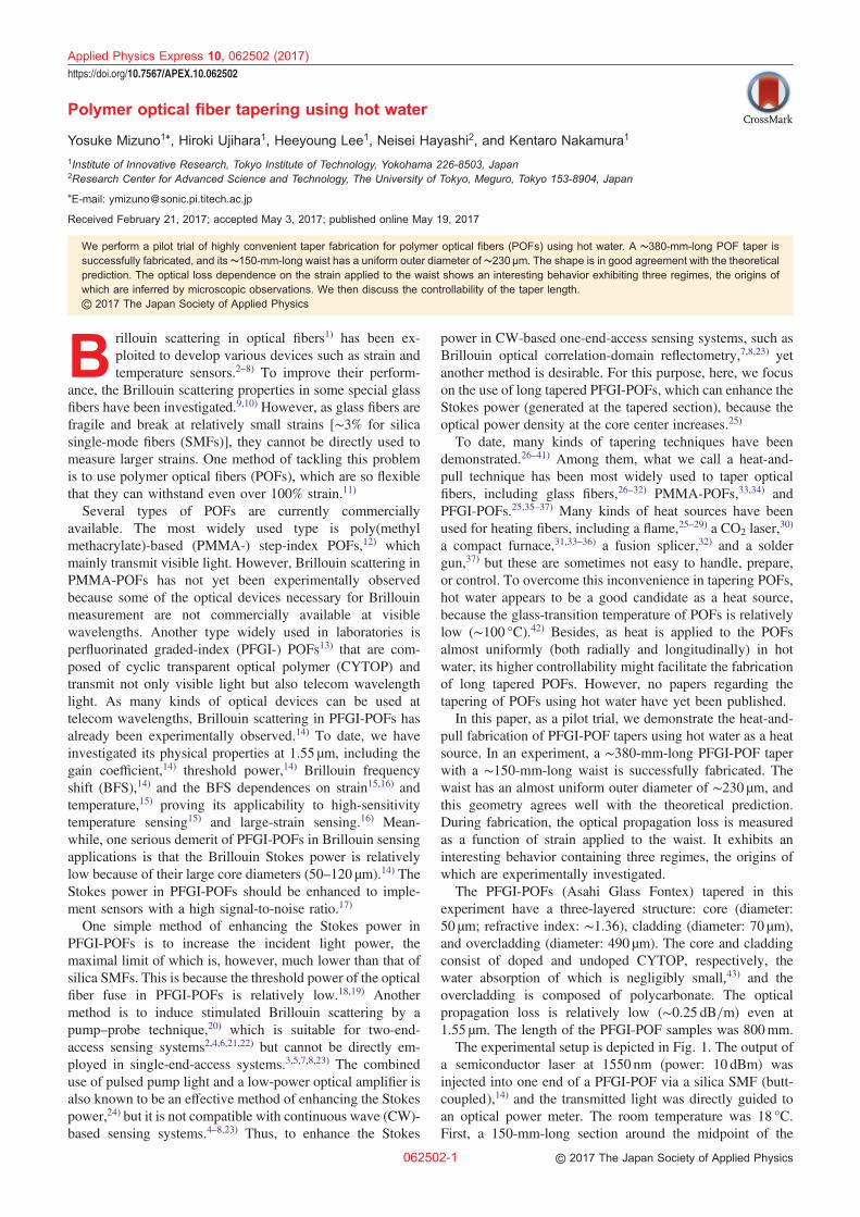
The experimental setup is depicted in Fig. 1. The output ofa semiconductor laser at 1550 nm (power: 10 dBm) wasinjected into one end of a PFGI-POF via a silica SMF (butt-coupled),14) and the transmitted light was directly guided toan optical power meter. The room temperature was 18 °C.First, a 150-mm-long section around the midpoint of the
Applied Physics Express 10, 062502 (2017)
https://doi.org/10.7567/APEX.10.062502
062502-1 © 2017 The Japan Society of Applied Physics
PFGI-POF was immersed in hot water (maintained at 97 °C)in a round vessel (diameter: 300mm), and the temporalvariation in the transmitted power was monitored until thepower became almost constant. Subsequently, the PFGI-POFwas pulled (or in other words, strained) in both directions viapulleys (diameter: 95mm) at a rate of 0.50mm=s (0.25mm=sfor each direction) until the PFGI-POF was completely cut.The transmitted power was also monitored during the pullingprocess. The same experiments were performed using otherPFGI-POF samples with different pulling periods (pullingstopped before the samples were cut), and the taperedsections were observed using an optical microscope.
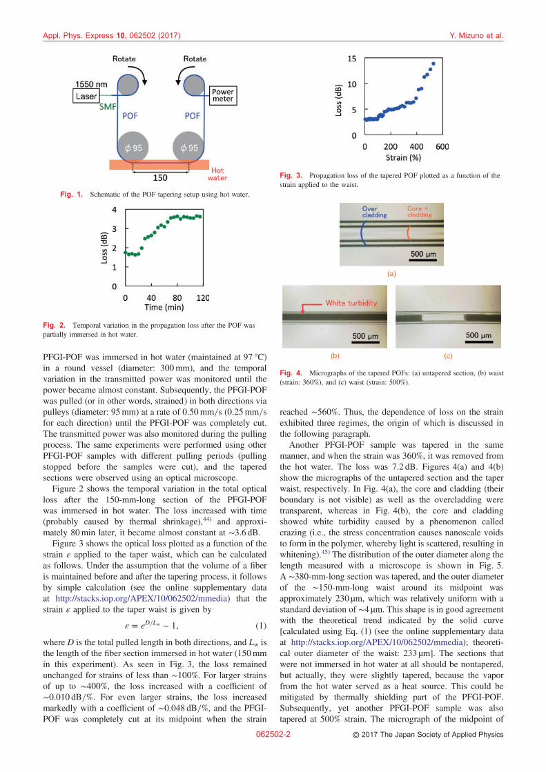
Figure 2 shows the temporal variation in the total opticalloss after the 150-mm-long section of the PFGI-POFwas immersed in hot water. The loss increased with time(probably caused by thermal shrinkage),44) and approxi-mately 80min later, it became almost constant at ∼3.6 dB.
Figure 3 shows the optical loss plotted as a function of thestrain ε applied to the taper waist, which can be calculatedas follows. Under the assumption that the volume of a fiberis maintained before and after the tapering process, it followsby simple calculation (see the online supplementary dataat http://stacks.iop.org/APEX/10/062502/mmedia) that thestrain ε applied to the taper waist is given by
" ¼ eD=Lw � 1; ð1Þwhere D is the total pulled length in both directions, and Lw isthe length of the fiber section immersed in hot water (150mmin this experiment). As seen in Fig. 3, the loss remainedunchanged for strains of less than ∼100%. For larger strainsof up to ∼400%, the loss increased with a coefficient of∼0.010 dB=%. For even larger strains, the loss increasedmarkedly with a coefficient of ∼0.048 dB=%, and the PFGI-POF was completely cut at its midpoint when the strain
reached ∼560%. Thus, the dependence of loss on the strainexhibited three regimes, the origin of which is discussed inthe following paragraph.
Another PFGI-POF sample was tapered in the samemanner, and when the strain was 360%, it was removed fromthe hot water. The loss was 7.2 dB. Figures 4(a) and 4(b)show the micrographs of the untapered section and the taperwaist, respectively. In Fig. 4(a), the core and cladding (theirboundary is not visible) as well as the overcladding weretransparent, whereas in Fig. 4(b), the core and claddingshowed white turbidity caused by a phenomenon calledcrazing (i.e., the stress concentration causes nanoscale voidsto form in the polymer, whereby light is scattered, resulting inwhitening).45) The distribution of the outer diameter along thelength measured with a microscope is shown in Fig. 5.A ∼380-mm-long section was tapered, and the outer diameterof the ∼150-mm-long waist around its midpoint wasapproximately 230 µm, which was relatively uniform with astandard deviation of ∼4 µm. This shape is in good agreementwith the theoretical trend indicated by the solid curve[calculated using Eq. (1) (see the online supplementary dataat http://stacks.iop.org/APEX/10/062502/mmedia); theoreti-cal outer diameter of the waist: 233 µm]. The sections thatwere not immersed in hot water at all should be nontapered,but actually, they were slightly tapered, because the vaporfrom the hot water served as a heat source. This could bemitigated by thermally shielding part of the PFGI-POF.Subsequently, yet another PFGI-POF sample was alsotapered at 500% strain. The micrograph of the midpoint of
Fig. 1. Schematic of the POF tapering setup using hot water.
Fig. 2. Temporal variation in the propagation loss after the POF waspartially immersed in hot water.
Fig. 3. Propagation loss of the tapered POF plotted as a function of thestrain applied to the waist.
(b) (c)
(a)
Fig. 4. Micrographs of the tapered POFs: (a) untapered section, (b) waist(strain: 360%), and (c) waist (strain: 500%).
Appl. Phys. Express 10, 062502 (2017) Y. Mizuno et al.
062502-2 © 2017 The Japan Society of Applied Physics
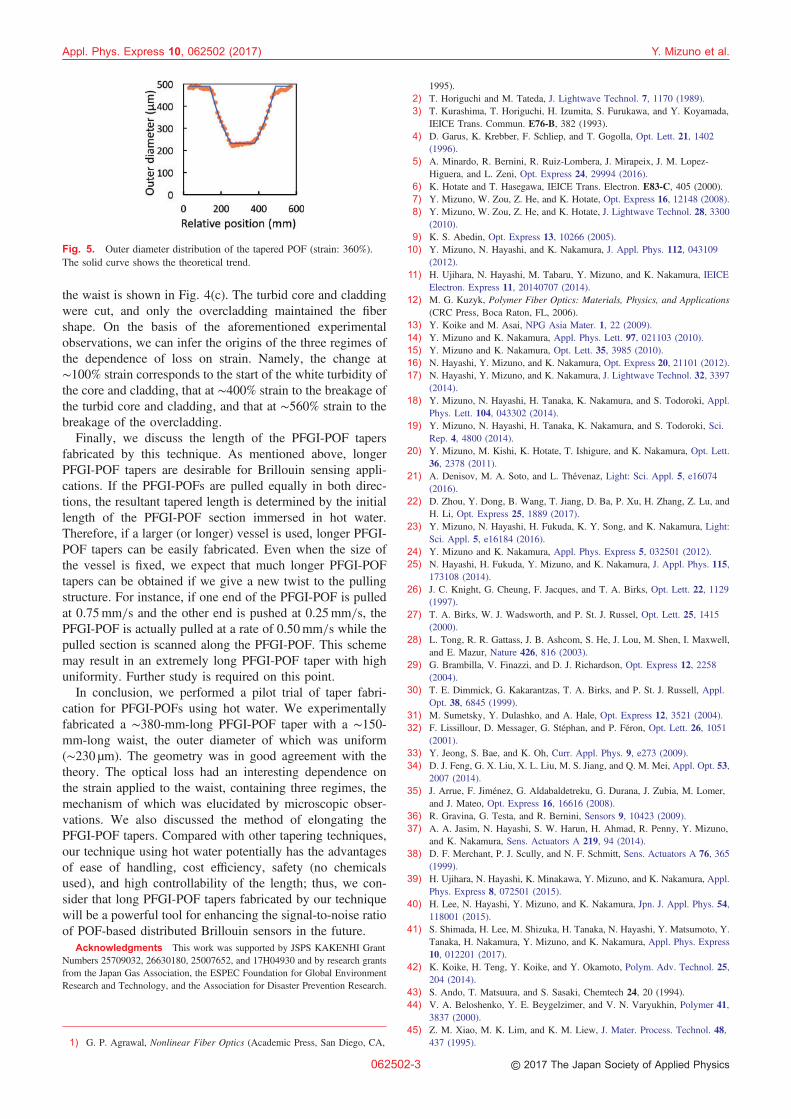
the waist is shown in Fig. 4(c). The turbid core and claddingwere cut, and only the overcladding maintained the fibershape. On the basis of the aforementioned experimentalobservations, we can infer the origins of the three regimes ofthe dependence of loss on strain. Namely, the change at∼100% strain corresponds to the start of the white turbidity ofthe core and cladding, that at ∼400% strain to the breakage ofthe turbid core and cladding, and that at ∼560% strain to thebreakage of the overcladding.
Finally, we discuss the length of the PFGI-POF tapersfabricated by this technique. As mentioned above, longerPFGI-POF tapers are desirable for Brillouin sensing appli-cations. If the PFGI-POFs are pulled equally in both direc-tions, the resultant tapered length is determined by the initiallength of the PFGI-POF section immersed in hot water.Therefore, if a larger (or longer) vessel is used, longer PFGI-POF tapers can be easily fabricated. Even when the size ofthe vessel is fixed, we expect that much longer PFGI-POFtapers can be obtained if we give a new twist to the pullingstructure. For instance, if one end of the PFGI-POF is pulledat 0.75mm=s and the other end is pushed at 0.25mm=s, thePFGI-POF is actually pulled at a rate of 0.50mm=s while thepulled section is scanned along the PFGI-POF. This schememay result in an extremely long PFGI-POF taper with highuniformity. Further study is required on this point.
In conclusion, we performed a pilot trial of taper fabri-cation for PFGI-POFs using hot water. We experimentallyfabricated a ∼380-mm-long PFGI-POF taper with a ∼150-mm-long waist, the outer diameter of which was uniform(∼230 µm). The geometry was in good agreement with thetheory. The optical loss had an interesting dependence onthe strain applied to the waist, containing three regimes, themechanism of which was elucidated by microscopic obser-vations. We also discussed the method of elongating thePFGI-POF tapers. Compared with other tapering techniques,our technique using hot water potentially has the advantagesof ease of handling, cost efficiency, safety (no chemicalsused), and high controllability of the length; thus, we con-sider that long PFGI-POF tapers fabricated by our techniquewill be a powerful tool for enhancing the signal-to-noise ratioof POF-based distributed Brillouin sensors in the future.
Acknowledgments This work was supported by JSPS KAKENHI GrantNumbers 25709032, 26630180, 25007652, and 17H04930 and by research grantsfrom the Japan Gas Association, the ESPEC Foundation for Global EnvironmentResearch and Technology, and the Association for Disaster Prevention Research.
1) G. P. Agrawal, Nonlinear Fiber Optics (Academic Press, San Diego, CA,
1995).2) T. Horiguchi and M. Tateda, J. Lightwave Technol. 7, 1170 (1989).3) T. Kurashima, T. Horiguchi, H. Izumita, S. Furukawa, and Y. Koyamada,
IEICE Trans. Commun. E76-B, 382 (1993).4) D. Garus, K. Krebber, F. Schliep, and T. Gogolla, Opt. Lett. 21, 1402
(1996).5) A. Minardo, R. Bernini, R. Ruiz-Lombera, J. Mirapeix, J. M. Lopez-
Higuera, and L. Zeni, Opt. Express 24, 29994 (2016).6) K. Hotate and T. Hasegawa, IEICE Trans. Electron. E83-C, 405 (2000).7) Y. Mizuno, W. Zou, Z. He, and K. Hotate, Opt. Express 16, 12148 (2008).8) Y. Mizuno, W. Zou, Z. He, and K. Hotate, J. Lightwave Technol. 28, 3300
(2010).9) K. S. Abedin, Opt. Express 13, 10266 (2005).
10) Y. Mizuno, N. Hayashi, and K. Nakamura, J. Appl. Phys. 112, 043109(2012).
11) H. Ujihara, N. Hayashi, M. Tabaru, Y. Mizuno, and K. Nakamura, IEICEElectron. Express 11, 20140707 (2014).
12) M. G. Kuzyk, Polymer Fiber Optics: Materials, Physics, and Applications(CRC Press, Boca Raton, FL, 2006).
13) Y. Koike and M. Asai, NPG Asia Mater. 1, 22 (2009).14) Y. Mizuno and K. Nakamura, Appl. Phys. Lett. 97, 021103 (2010).15) Y. Mizuno and K. Nakamura, Opt. Lett. 35, 3985 (2010).16) N. Hayashi, Y. Mizuno, and K. Nakamura, Opt. Express 20, 21101 (2012).17) N. Hayashi, Y. Mizuno, and K. Nakamura, J. Lightwave Technol. 32, 3397
(2014).18) Y. Mizuno, N. Hayashi, H. Tanaka, K. Nakamura, and S. Todoroki, Appl.
Phys. Lett. 104, 043302 (2014).19) Y. Mizuno, N. Hayashi, H. Tanaka, K. Nakamura, and S. Todoroki, Sci.
Rep. 4, 4800 (2014).20) Y. Mizuno, M. Kishi, K. Hotate, T. Ishigure, and K. Nakamura, Opt. Lett.
36, 2378 (2011).21) A. Denisov, M. A. Soto, and L. Thévenaz, Light: Sci. Appl. 5, e16074
(2016).22) D. Zhou, Y. Dong, B. Wang, T. Jiang, D. Ba, P. Xu, H. Zhang, Z. Lu, and
H. Li, Opt. Express 25, 1889 (2017).23) Y. Mizuno, N. Hayashi, H. Fukuda, K. Y. Song, and K. Nakamura, Light:
Sci. Appl. 5, e16184 (2016).24) Y. Mizuno and K. Nakamura, Appl. Phys. Express 5, 032501 (2012).25) N. Hayashi, H. Fukuda, Y. Mizuno, and K. Nakamura, J. Appl. Phys. 115,
173108 (2014).26) J. C. Knight, G. Cheung, F. Jacques, and T. A. Birks, Opt. Lett. 22, 1129
(1997).27) T. A. Birks, W. J. Wadsworth, and P. St. J. Russel, Opt. Lett. 25, 1415
(2000).28) L. Tong, R. R. Gattass, J. B. Ashcom, S. He, J. Lou, M. Shen, I. Maxwell,
and E. Mazur, Nature 426, 816 (2003).29) G. Brambilla, V. Finazzi, and D. J. Richardson, Opt. Express 12, 2258
(2004).30) T. E. Dimmick, G. Kakarantzas, T. A. Birks, and P. St. J. Russell, Appl.
Opt. 38, 6845 (1999).31) M. Sumetsky, Y. Dulashko, and A. Hale, Opt. Express 12, 3521 (2004).32) F. Lissillour, D. Messager, G. Stéphan, and P. Féron, Opt. Lett. 26, 1051
(2001).33) Y. Jeong, S. Bae, and K. Oh, Curr. Appl. Phys. 9, e273 (2009).34) D. J. Feng, G. X. Liu, X. L. Liu, M. S. Jiang, and Q. M. Mei, Appl. Opt. 53,
2007 (2014).35) J. Arrue, F. Jiménez, G. Aldabaldetreku, G. Durana, J. Zubia, M. Lomer,
and J. Mateo, Opt. Express 16, 16616 (2008).36) R. Gravina, G. Testa, and R. Bernini, Sensors 9, 10423 (2009).37) A. A. Jasim, N. Hayashi, S. W. Harun, H. Ahmad, R. Penny, Y. Mizuno,
and K. Nakamura, Sens. Actuators A 219, 94 (2014).38) D. F. Merchant, P. J. Scully, and N. F. Schmitt, Sens. Actuators A 76, 365
(1999).39) H. Ujihara, N. Hayashi, K. Minakawa, Y. Mizuno, and K. Nakamura, Appl.
Phys. Express 8, 072501 (2015).40) H. Lee, N. Hayashi, Y. Mizuno, and K. Nakamura, Jpn. J. Appl. Phys. 54,
118001 (2015).41) S. Shimada, H. Lee, M. Shizuka, H. Tanaka, N. Hayashi, Y. Matsumoto, Y.
Tanaka, H. Nakamura, Y. Mizuno, and K. Nakamura, Appl. Phys. Express10, 012201 (2017).
42) K. Koike, H. Teng, Y. Koike, and Y. Okamoto, Polym. Adv. Technol. 25,204 (2014).
43) S. Ando, T. Matsuura, and S. Sasaki, Chemtech 24, 20 (1994).44) V. A. Beloshenko, Y. E. Beygelzimer, and V. N. Varyukhin, Polymer 41,
3837 (2000).45) Z. M. Xiao, M. K. Lim, and K. M. Liew, J. Mater. Process. Technol. 48,
437 (1995).
Fig. 5. Outer diameter distribution of the tapered POF (strain: 360%).The solid curve shows the theoretical trend.
Appl. Phys. Express 10, 062502 (2017) Y. Mizuno et al.
062502-3 © 2017 The Japan Society of Applied Physics