Embed Size (px)
Citation preview
Polymer InsulatorsA Better Solution
October 2016
LET’SCONNECT
POLYMER INSULATORS
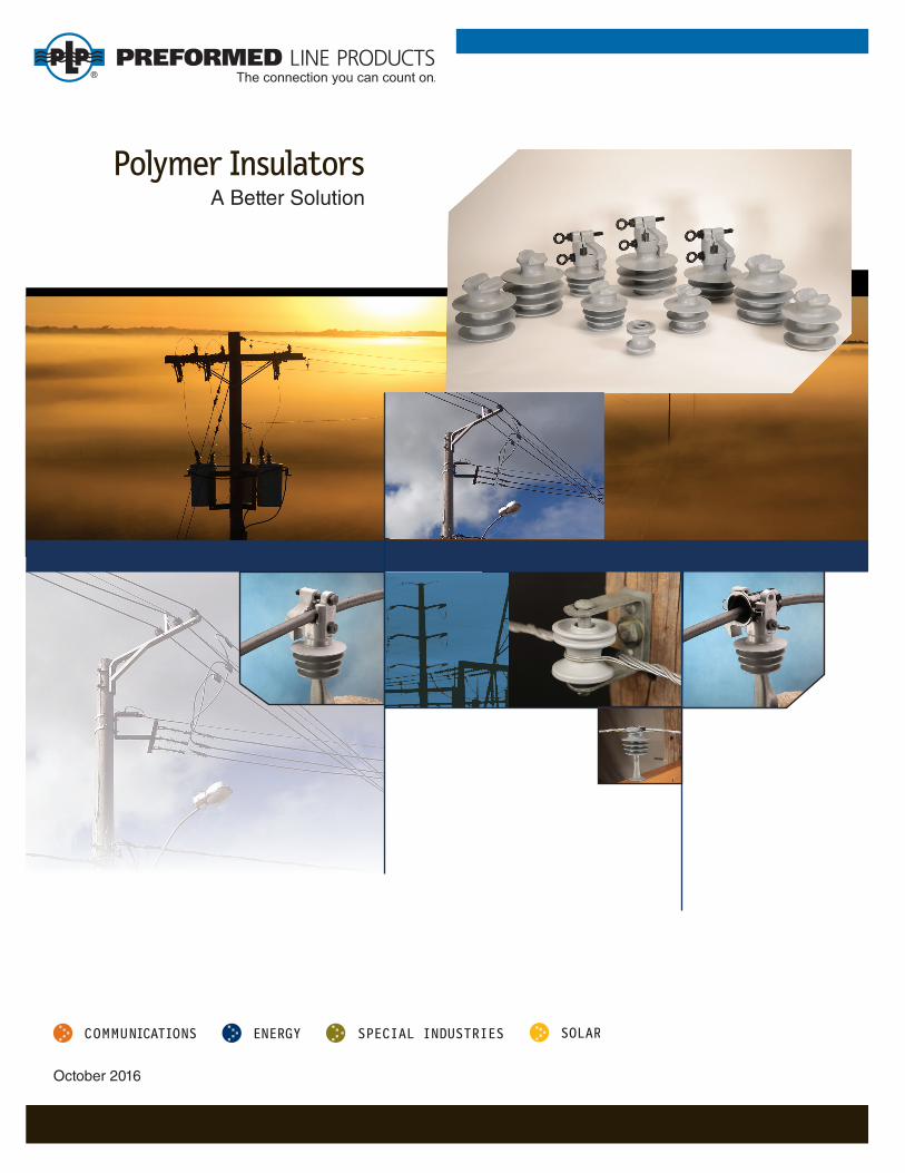
• Design derived from PLP’s many years of worldwide experience and tested to adhere to ANSI C29.5 and ANSI 29.6 insulator standards
• Usable for any application that calls for porcelain or polymer pin insulators, and suitable for use with all types of jacketed or bare conductors.
• Currently available in a line of 15, 25 and 35kV Tie Top and Vise Top designs for 1" or 1-3/8" pins
• Specifi cally designed for use with PLP formed wire ties, plastic ties and hand tie wire
• Unique descending skirt design and polyethylene surface provide superior mois-ture and contamination shedding properties
440.461.5200 • www.preformed.com • [email protected]
Polymer Insulators
Table of Contents
Polymer Insulator Introduction ......................................................................................................... 1
Polymer Insulators – Tie Top ............................................................................................................ 2
Polymer Insulators – Vise Top .......................................................................................................... 6
Polymer Insulators – Accessories .................................................................................................. 10
Polymer Insulators – Spool Insulators ............................................................................................11
Additional Polymer Insulator Information Available from PLP:
SP3245 – Polymer Insulator: Tie Top Application Procedure
SP3032 – Polymer Insulator: Vise Top (VT) Application Procedure
EN-SS-1162 – Polymer Insulator: Vise Top Sell Sheet
EN-SS-1132 – Polymer Insulator: Tie Top Sell Sheet


Polymer Insulators
1(440) 461-5200 • [email protected] • www.preformed.com • EN-ML-1022-9
The PLP Polymer Insulators are for use in over-head distribution lines using bare or covered con-ductors. They are particularly suited for use with Spacer Cable and Tree Wire as a better electrical alternative to porcelain insulators.
PLP Polymer Insulators are manufactured from a proprietary, high-density polyethylene-based compound having a dielectric constant that is compatible with polyethylene-covered conductors.
These insulators are designed to meet the applicable dimensional, electrical, and mechanical requirements of the ANSI C29.5 and C29.6 pin-type insulator standards, even though these standards apply only to Wet-Process Porcelain Insulators. These insulators can be used in any application that calls for porcelain insulators requiring adherence to these ANSI standards.
Two basic designs are offered: Tie Top and Vise Top Insulators, both available for application on 1" or 1-3/8" pins depending upon the specifi c ANSI class or voltage application.
The Tie Top Insulators are designed to meet pertinent ANSI C29.5 and C29.6 insulator head dimensional standards for appropriate insulator classes with “C”, “F” or “J” necks. Therefore, they are compatible with all PLP Formed Wire and Plastic Ties, and covered or bare tie wire.
The Vise Top Insulators employ a unique clamp style head. While they are also designed to meet certain ANSI standards, the clamp style head design is not applicable to ANSI tie top insulator head dimensional standards.
BENEFITS• ANSI compliant tie top head design facilitates the use
of factory-formed ties for exceptional fi t and perfor-mance matching.
• The Polymer Insulators closely match the dielectric properties of the covered conductor jacket.
• The polyethylene surface, coupled with the multiple skirt design with descending skirt diameters and long leakage distances, provides superior moisture and contamination shedding properties.
• UV-stabilized for long-term service.
• High impact resistance – designed to reduce break-age and vandal/gun shot damage, particularly at cold temperatures.
• The lightweight design reduces shipping costs and lineman handling requirements.
• Polyethylene material eliminates abrasion of the conductor at the insulator/conductor interface.
• Polymer Insulators can be used with jacketed jumper wires, eliminating skinning, and providing additional wildlife protection at equipment locations.
Polymer Insulators – Tie Top
2(440) 461-5200 • [email protected] • www.preformed.com • EN-ML-1022-9
ANSI Class:55-3, 55-4, 55-5, 55-6, 55-7, 56-1
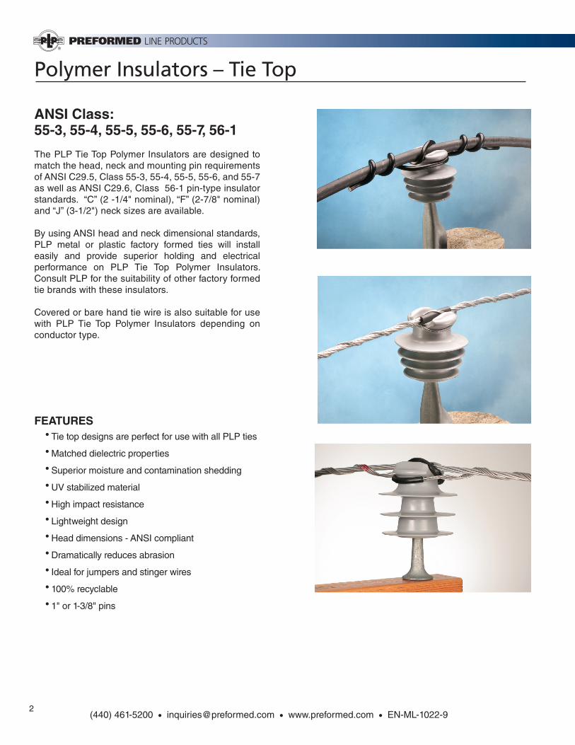
The PLP Tie Top Polymer Insulators are designed to match the head, neck and mounting pin requirements of ANSI C29.5, Class 55-3, 55-4, 55-5, 55-6, and 55-7 as well as ANSI C29.6, Class 56-1 pin-type insulator standards. “C” (2 -1/4" nominal), “F” (2-7/8" nominal) and “J” (3-1/2") neck sizes are available.
By using ANSI head and neck dimensional standards, PLP metal or plastic factory formed ties will install easily and provide superior holding and electrical performance on PLP Tie Top Polymer Insulators. Consult PLP for the suitability of other factory formed tie brands with these insulators.
Covered or bare hand tie wire is also suitable for use with PLP Tie Top Polymer Insulators depending on conductor type.
FEATURES• Tie top designs are perfect for use with all PLP ties
• Matched dielectric properties
• Superior moisture and contamination shedding
• UV stabilized material
• High impact resistance
• Lightweight design
• Head dimensions - ANSI compliant
• Dramatically reduces abrasion
• Ideal for jumpers and stinger wires
• 100% recyclable
• 1" or 1-3/8" pins
Polymer Insulators – Tie Top
3(440) 461-5200 • [email protected] • www.preformed.com • EN-ML-1022-9
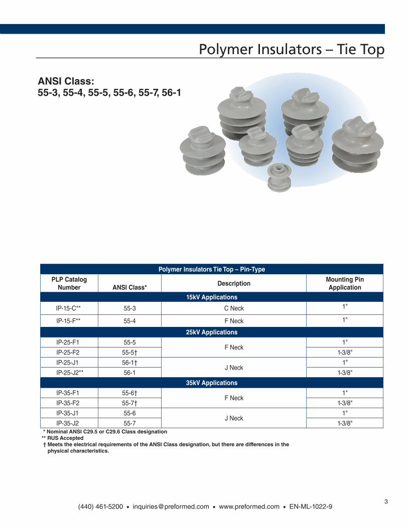
ANSI Class:55-3, 55-4, 55-5, 55-6, 55-7, 56-1
Polymer Insulators Tie Top – Pin-Type
PLP Catalog Number ANSI Class*
DescriptionMounting Pin Application
15kV Applications
IP-15-C** 55-3 C Neck 1"
IP-15-F** 55-4 F Neck 1"
25kV Applications
IP-25-F1 55-5F Neck
1"
IP-25-F2 55-5† 1-3/8"
IP-25-J1 56-1†J Neck
1”
IP-25-J2** 56-1 1-3/8"
35kV Applications
IP-35-F1 55-6†F Neck
1"
IP-35-F2 55-7† 1-3/8"
IP-35-J1 55-6J Neck
1"
IP-35-J2 55-7 1-3/8" * Nominal ANSI C29.5 or C29.6 Class designation ** RUS Accepted † Meets the electrical requirements of the ANSI Class designation, but there are differences in the physical characteristics.
Polymer Insulators – Tie Top
4 (440) 461-5200 • [email protected] • www.preformed.com • EN-ML-1022-9
A
B
D
C
ERadius
FRadius
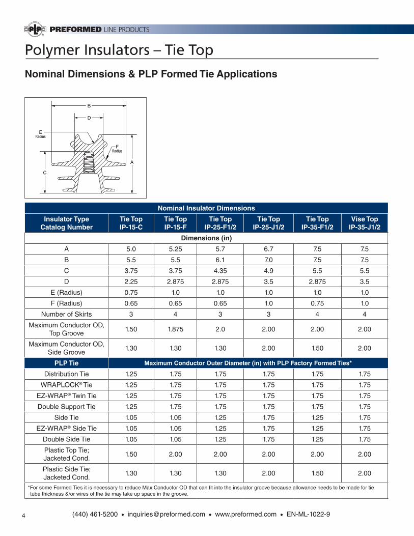
Nominal Insulator Dimensions
Insulator TypeCatalog Number
Tie TopIP-15-C
Tie TopIP-15-F
Tie TopIP-25-F1/2
Tie TopIP-25-J1/2
Tie TopIP-35-F1/2
Vise TopIP-35-J1/2
Dimensions (in)
A 5.0 5.25 5.7 6.7 7.5 7.5
B 5.5 5.5 6.1 7.0 7.5 7.5
C 3.75 3.75 4.35 4.9 5.5 5.5
D 2.25 2.875 2.875 3.5 2.875 3.5
E (Radius) 0.75 1.0 1.0 1.0 1.0 1.0
F (Radius) 0.65 0.65 0.65 1.0 0.75 1.0
Number of Skirts 3 4 3 3 4 4
Maximum Conductor OD, Top Groove
1.50 1.875 2.0 2.00 2.00 2.00
Maximum Conductor OD, Side Groove
1.30 1.30 1.30 2.00 1.50 2.00
PLP Tie Maximum Conductor Outer Diameter (in) with PLP Factory Formed Ties*
Distribution Tie 1.25 1.75 1.75 1.75 1.75 1.75
WRAPLOCK® Tie 1.25 1.75 1.75 1.75 1.75 1.75
EZ-WRAP® Twin Tie 1.25 1.75 1.75 1.75 1.75 1.75
Double Support Tie 1.25 1.75 1.75 1.75 1.75 1.75
Side Tie 1.05 1.05 1.25 1.75 1.25 1.75
EZ-WRAP® Side Tie 1.05 1.05 1.25 1.75 1.25 1.75
Double Side Tie 1.05 1.05 1.25 1.75 1.25 1.75
Plastic Top Tie; Jacketed Cond.
1.50 2.00 2.00 2.00 2.00 2.00
Plastic Side Tie; Jacketed Cond.
1.30 1.30 1.30 2.00 1.50 2.00
*For some Formed Ties it is necessary to reduce Max Conductor OD that can fi t into the insulator groove because allowance needs to be made for tie tube thickness &/or wires of the tie may take up space in the groove.
Nominal Dimensions & PLP Formed Tie Applications
Polymer Insulators – Tie Top
5(440) 461-5200 • [email protected] • www.preformed.com • EN-ML-1022-9
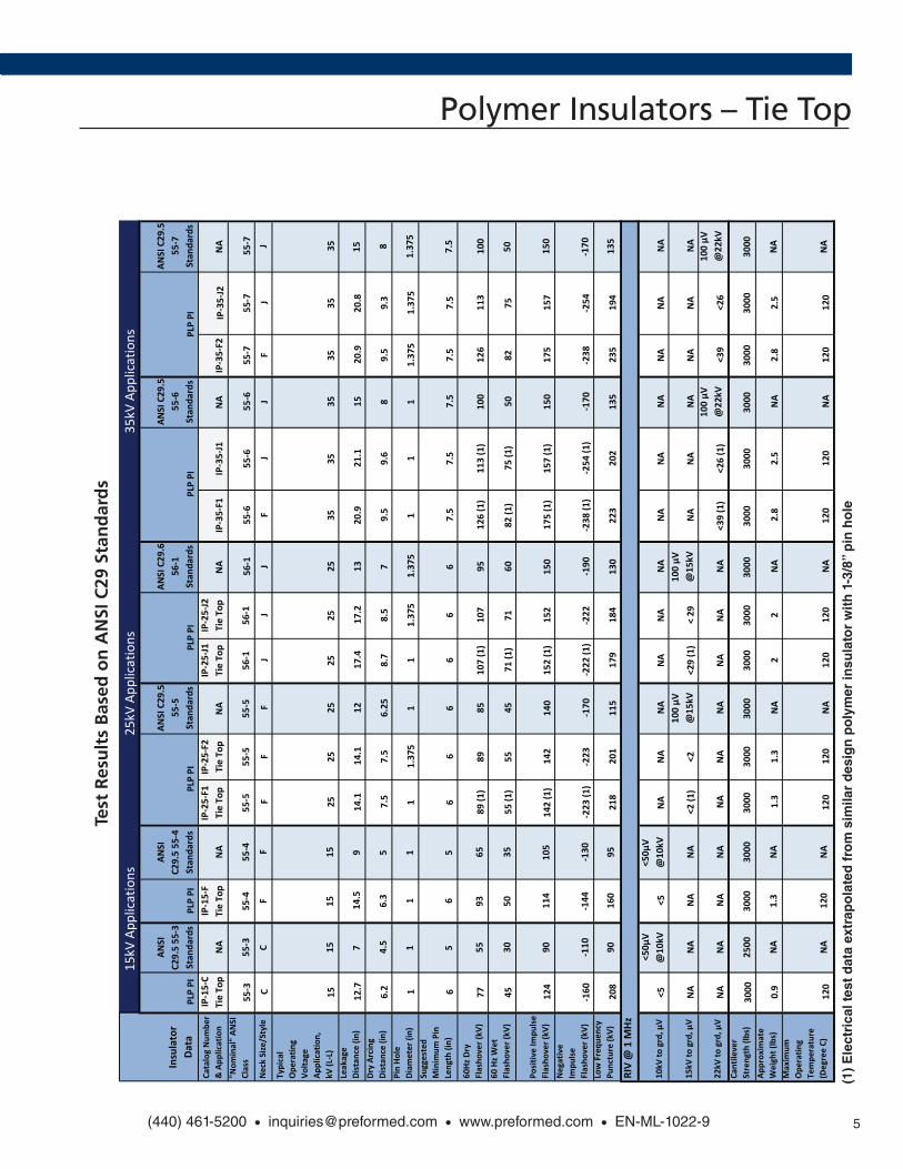
TestResultsonAN
SIC29
Stand
ard
PLPTieTo
pPo
lymerInsulators
PLPPI
ANSI
C29.555-3
StandardsPLPPI
ANSI
C29.555-4
Standards
ANSIC29.5
55-5
Standards
ANSIC29.6
56-1
Standards
ANSIC29.5
55-6
Standards
ANSIC29.5
55-7
Standards
CatalogNumber
&Application
IP-15-C
TieTop
NA
IP-15-F
TieTop
NA
IP-25-F1
TieTop
IP-25-F2
TieTop
NA
IP-25-J1
TieTop
IP-25-J2
TieTop
NA
IP-35-F1
IP-35-J1
NA
IP-35-F2
IP-35-J2
NA
"Nominal"ANSI
Class
55-3
55-3
55-4
55-4
55-5
55-5
55-5
56-1
56-1
56-1
55-6
55-6
55-6
55-7
55-7
55-7
NeckSize/Style
CC
FF
FF
FJ
JJ
FJ
JF
JJ
Typical
Operating
Voltage
Application,
kV(L-L)
1515
1515
2525
2525
2525
3535
3535
3535
Leakage
Distance(in)
12.7
714.5
914.1
14.1
1217.4
17.2
1320.9
21.1
1520.9
20.8
15DryArcing
Distance(in)
6.2
4.5
6.3
57.5
7.5
6.25
8.7
8.5
79.5
9.6
89.5
9.3
8PinHole
Diameter(in)
11
11
11.375
11
1.375
1.375
11
11.375
1.375
1.375
Suggested
MinimumPin
Length(in)
65
65
66
66
66
7.5
7.5
7.5
7.5
7.5
7.5
60HzDry
Flashover(kV)
7755
9365
89(1)
8985
107(1)
107
95126(1)
113(1)
100
126
113
100
60HzWet
Flashover(kV)
4530
5035
55(1)
5545
71(1)
7160
82(1)
75(1)
5082
7550
PositiveImpulse
Flashover(kV)
124
90114
105
142(1)
142
140
152(1)
152
150
175(1)
157(1)
150
175
157
150
Negative
Impulse
Flashover(kV)
-160
-110
-144
-130
-223(1)
-223
-170
-222(1)
-222
-190
-238(1)
-254(1)
-170
-238
-254
-170
LowFrequency
Puncture(kV)
208
90160
95218
201
115
179
184
130
223
202
135
235
194
135
RIV@1MHz
10kVtogrd,µV
<5<50µV
@10kV
<5<50µV
@10kV
NA
NA
NA
NA
NA
NA
NA
NA
NA
NA
NA
NA
15kVtogrd,µV
NA
NA
NA
NA
<2(1)
<2100µV
@15kV
<29(1)
<29
100µV
@15kV
NA
NA
NA
NA
NA
NA
22kVtogrd,µV
NA
NA
NA
NA
NA
NA
NA
NA
NA
NA
<39(1)
<26(1)
100µV
@22kV
<39
<26
100µV
@22kV
Cantilever
Strength(lbs)
3000
2500
3000
3000
3000
3000
3000
3000
3000
3000
3000
3000
3000
3000
3000
3000
Approximate
Weight(lbs)
0.9
NA
1.3
NA
1.3
1.3
NA
22
NA
2.8
2.5
NA
2.8
2.5
NA
Maximum
Operating
Temperature
(DegreeC)
120
NA
120
NA
120
120
NA
120
120
NA
120
120
NA
120
120
NA
PLPPI
PLPPI
PLPPI
25kV
App
lications
35kV
App
lications
Insulator
Data
15kV
App
lications
PLPPI
Test
Res
ult
s B
ased
on
AN
SI C
29 S
tan
dar
ds
(1)
Ele
ctri
cal t
est
dat
a ex
trap
ola
ted
fro
m s
imila
r d
esig
n p
oly
mer
insu
lato
r w
ith
1-3
/8”
pin
ho
le
Polymer Insulators – Vise Top
6(440) 461-5200 • [email protected] • www.preformed.com • EN-ML-1022-9
ANSI Class:55-3, 55-4, 55-5, 55-6, 55-7
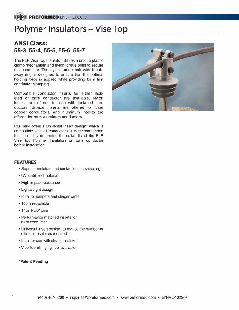
The PLP Vise Top Insulator utilizes a unique plastic clamp mechanism and nylon torque bolts to secure the conductor. The nylon torque bolt with break-away ring is designed to ensure that the optimal holding force is applied while providing for a fast conductor clamping.
Compatible conductor inserts for either jack-eted or bare conductor are available. Nylon inserts are offered for use with jacketed con-ductors. Bronze inserts are offered for bare copper conductors, and aluminum inserts are offered for bare aluminum conductors.
PLP also offers a Universal Insert design* which is compatible with all conductors. It is recommended that the utility determine the suitability of the PLP Vise Top Polymer Insulators on bare conductor before installation.
FEATURES• Superior moisture and contamination shedding
• UV stabilized material
• High impact resistance
• Lightweight design
• Ideal for jumpers and stinger wires
• 100% recyclable
• 1" or 1-3/8" pins
• Performance matched inserts for bare conductor
• Universal Insert design* to reduce the number of different insulators required
• Ideal for use with shot gun sticks
• Vise Top Stringing Tool available
*Patent Pending
Polymer Insulators – Vise Top
7
ANSI Class:55-3, 55-4, 55-5, 55-6, 55-7
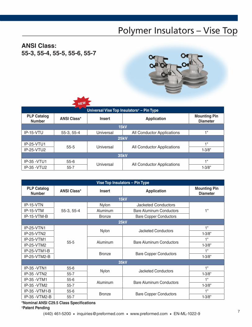
Universal Vise Top Insulators✝ – Pin TypePLP Catalog
NumberANSI Class* Insert Application
Mounting Pin Diameter
15kV IP-15-VTU 55-3, 55-4 Universal All Conductor Applications 1"
25kV IP-25-VTU1
55-5 Universal All Conductor Applications 1"
IP-25-VTU2 1-3/8"35kV
IP-35 -VTU1 55-6Universal All Conductor Applications
1" IP-35 -VTU2 55-7 1-3/8"
Vise Top Insulators – Pin TypePLP Catalog
NumberANSI Class* Insert Application
Mounting Pin Diameter
15kV IP-15-VTN
55-3, 55-4Nylon Jacketed Conductors
1" IP-15-VTM Aluminum Bare Aluminum Conductors IP-15-VTM-B Bronze Bare Copper Conductors
25kV IP-25-VTN1
55-5
Nylon Jacketed Conductors 1"
IP-25-VTN2 1-3/8" IP-25-VTM1
Aluminum Bare Aluminum Conductors1"
IP-25-VTM2 1-3/8" IP-25-VTM1-B
Bronze Bare Copper Conductors 1"
IP-25-VTM2-B 1-3/8"35kV
IP-35 -VTN1 55-6Nylon Jacketed Conductors
1" IP-35 -VTN2 55-7 1-3/8" IP-35 -VTM1 55-6
Aluminum Bare Aluminum Conductors1"
IP-35 -VTM2 55-7 1-3/8" IP-35 -VTM1-B 55-6
Bronze Bare Copper Conductors 1"
IP-35 -VTM2-B 55-7 1-3/8"
*Nominal ANSI C29.5 Class Specifi cations ✝Patent Pending
(440) 461-5200 • [email protected] • www.preformed.com • EN-ML-1022-9
NEW
Polymer Insulators – Vise Top
8(440) 461-5200 • [email protected] • www.preformed.com • EN-ML-1022-9
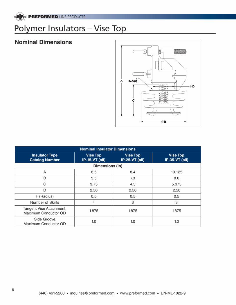
Nominal Insulator Dimensions
Insulator TypeCatalog Number
Vise TopIP-15-VT (all)
Vise TopIP-25-VT (all)
Vise TopIP-35-VT (all)
Dimensions (in)
A 8.5 8.4 10.125
B 5.5 7.3 8.0
C 3.75 4.5 5.375
D 2.50 2.50 2.50
F (Radius) 0.5 0.5 0.5
Number of Skirts 4 3 3
Tangent Vise Attachment, Maximum Conductor OD
1.875 1.875 1.875
Side Groove, Maximum Conductor OD
1.0 1.0 1.0
Nominal Dimensions
Polymer Insulators – Vise Top
9(440) 461-5200 • [email protected] • www.preformed.com • EN-ML-1022-9
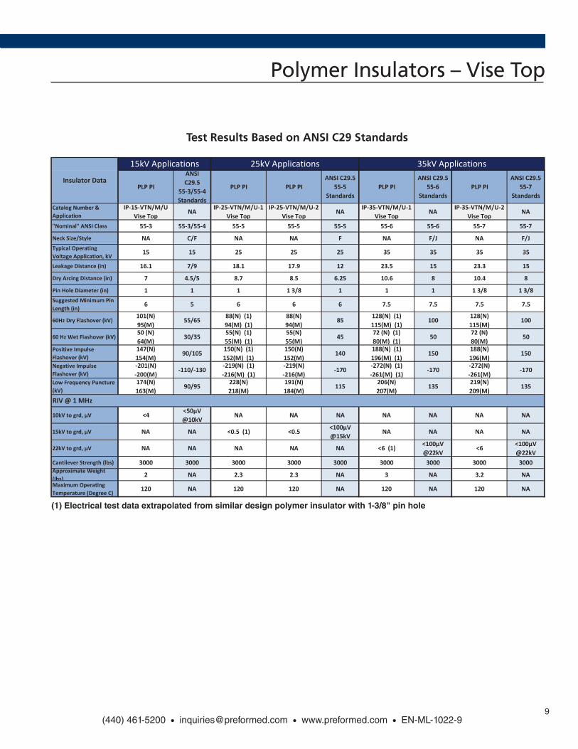
PLP PI
ANSI C29.5
55-3/55-4 Standards
PLP PI PLP PIANSI C29.5
55-5 Standards
PLP PIANSI C29.5
55-6 Standards
PLP PIANSI C29.5
55-7 Standards
Catalog Number & Application
IP-15-VTN/M/U Vise Top
NA IP-25-VTN/M/U-1 Vise Top
IP-25-VTN/M/U-2 Vise Top
NA IP-35-VTN/M/U-1 Vise Top
NA IP-35-VTN/M/U-2 Vise Top
NA
"Nominal" ANSI Class 55-3 55-3/55-4 55-5 55-5 55-5 55-6 55-6 55-7 55-7
Neck Size/Style NA C/F NA NA F NA F/J NA F/JTypical Operating Voltage Application, kV
15 15 25 25 25 35 35 35 35
Leakage Distance (in) 16.1 7/9 18.1 17.9 12 23.5 15 23.3 15
Dry Arcing Distance (in) 7 4.5/5 8.7 8.5 6.25 10.6 8 10.4 8
Pin Hole Diameter (in) 1 1 1 1 3/8 1 1 1 1 3/8 1 3/8Suggested Minimum Pin Length (in)
6 5 6 6 6 7.5 7.5 7.5 7.5
60Hz Dry Flashover (kV)101(N) 95(M)
55/65 88(N) (1) 94(M) (1)
88(N) 94(M)
85 128(N) (1) 115(M) (1)
100 128(N) 115(M)
100
60 Hz Wet Flashover (kV)50 (N) 64(M)
30/35 55(N) (1) 55(M) (1)
55(N) 55(M)
45 72 (N) (1) 80(M) (1)
50 72 (N) 80(M)
50
Positive Impulse Flashover (kV)
147(N) 154(M)
90/105 150(N) (1) 152(M) (1)
150(N) 152(M)
140 188(N) (1) 196(M) (1)
150 188(N) 196(M)
150
Negative Impulse Flashover (kV)
-201(N) -200(M)
-110/-130 -219(N) (1) -216(M) (1)
-219(N) -216(M)
-170 -272(N) (1) -261(M) (1)
-170 -272(N) -261(M)
-170
Low Frequency Puncture (kV)
174(N) 163(M)
90/95 228(N) 218(M)
191(N) 184(M)
115 206(N) 207(M)
135 219(N) 209(M)
135
10kV to grd, µV <4 <50µV @10kV
NA NA NA NA NA NA NA
15kV to grd, µV NA NA <0.5 (1) <0.5 <100µV @15kV
NA NA NA NA
22kV to grd, µV NA NA NA NA NA <6 (1) <100µV @22kV
<6 <100µV @22kV
Cantilever Strength (lbs) 3000 3000 3000 3000 3000 3000 3000 3000 3000Approximate Weight (lbs) 2 NA 2.3 2.3 NA 3 NA 3.2 NAMaximum Operating Temperature (Degree C)
120 NA 120 120 NA 120 NA 120 NA
(1) Electrical test data extrapolated from similar design polymer insulator with 1-3/8" pin hole
Test Results Based on ANSI C29 Standard
Insulator Data
15kV Applications 25kV Applications 35kV Applications
RIV @ 1 MHz
Test Results Based on ANSI C29 Standards
(1) Electrical test data extrapolated from similar design polymer insulator with 1-3/8" pin hole
Polymer Insulators – Vise Top Accessories
10
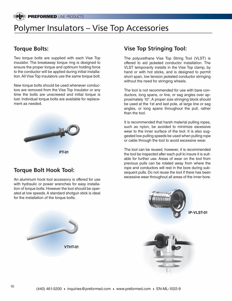
Torque Bolts:
Two torque bolts are supplied with each Vise Top insulator. The breakaway torque ring is designed to ensure the proper torque and optimum holding force to the conductor will be applied during initial installa-tion. All Vise Top insulators use the same torque bolt.
New torque bolts should be used whenever conduc-tors are removed from the Vise Top Insulator or any time the bolts are unscrewed and initial torque is lost. Individual torque bolts are available for replace-ment as needed.
Torque Bolt Hook Tool:
An aluminum hook tool accessory is offered for use with hydraulic or power wrenches for easy installa-tion of torque bolts. However the tool should be oper-ated at low speeds. A standard shotgun stick is ideal for the installation of the torque bolts.
Vise Top Stringing Tool:
The polyurethane Vise Top String Tool (VLST) is offered to aid jacketed conductor installation. The VLST temporarily installs in the Vise Top clamp, by hand or with hot sticks, and is designed to permit short span, low tension jacketed conductor stringing without the need for stringing wheels.
The tool is not recommended for use with bare con-ductors, long spans, or line, or sag angles over ap-proximately 10°. A proper size stringing block should be used at the 1st and last pole, at large line or sag angles, or long spans throughout the pull, rather than the tool.
It is recommended that harsh material pulling ropes, such as nylon, be avoided to minimize excessive wear to the inner surface of the tool. It is also sug-gested low pulling speeds be used when pulling rope or cable through the tool to avoid excessive wear.
The tool can be reused, however, it is recommended the tool be inspected after each pull to insure it is suit-able for further use. Areas of wear on the tool from previous pulls can be rotated away from where the rope and conductors will rest in the bore during sub-sequent pulls. Do not reuse the tool if there has been excessive wear throughout all areas of the inner bore.
PT-01
VTHT-01
IP-VLST-01
(440) 461-5200 • [email protected] • www.preformed.com • EN-ML-1022-9
Polymer Insulators – Spool Insulators
11
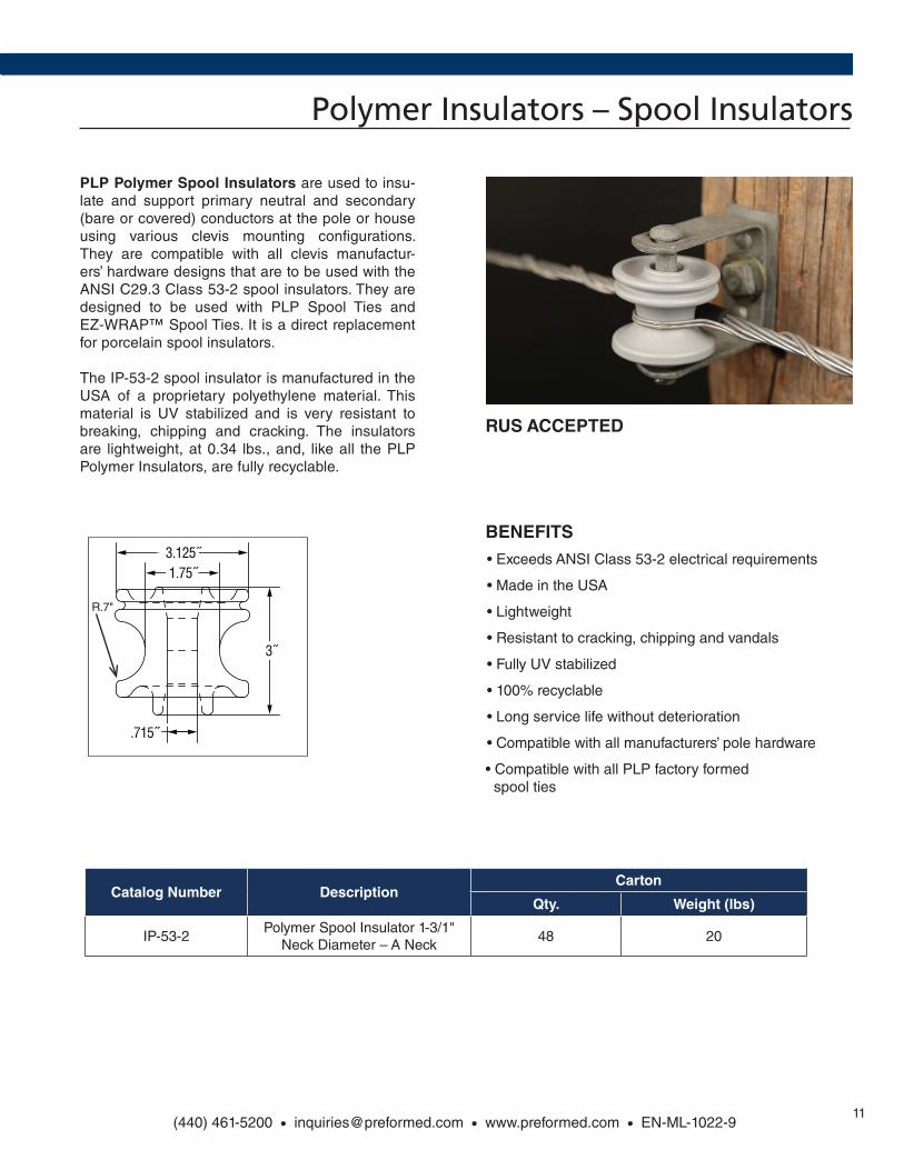
PLP Polymer Spool Insulators are used to insu-late and support primary neutral and secondary (bare or covered) conductors at the pole or house using various clevis mounting confi gurations. They are compatible with all clevis manufactur-ers’ hardware designs that are to be used with the ANSI C29.3 Class 53-2 spool insulators. They are designed to be used with PLP Spool Ties and EZ-WRAP™ Spool Ties. It is a direct replacement for porcelain spool insulators.
The IP-53-2 spool insulator is manufactured in the USA of a proprietary polyethylene material. This material is UV stabilized and is very resistant to breaking, chipping and cracking. The insulators are lightweight, at 0.34 lbs., and, like all the PLP Polymer Insulators, are fully recyclable.
13-8
(440) 461-5200 • [email protected] • www.preformed.com • EN-CA-1000-3
Polymer Spool Insulator
NOMENCLATURE
GENERAL RECOMMENDATIONS
The PLP Polymer Spool Insulators are used to insulate and support primary neutral and secondary (bare or cov-ered) conductors at the pole or house using various clevis mounting configurations. They are compatible with all manufacturers’ hardware designs that are to be used with the ANSI C29.3 Class 53-2 spool insulators. They are de-signed to be used with PLP Spool Ties and EZ-WRAP™ Spool Ties and are Class 53-2 compliant. The IP-53-2 is a direct replacement for porcelain spool insulators.
The IP-53-2 spool insulator is manufactured in the USA of a proprietary polyethylene material. This material is UV stabilized and is very resistant to breaking, chipping and cracking. The insulators are lightweight, at 0.34 lbs., and, like all the PLP polymer insulators, are fully recyclable.
Benefits: • Exceeds ANSI Class 53-2 electrical requirements
• Made in the USA
• Lightweight
• Resistant to cracking, chipping and vandals
• Fully UV stabilized
• Recyclable
• Long service life without deterioration
• Compatible with all manufacturers’ pole hardware
• Compatible with all PLP factory formed ties for spool applications
Catalog # Description
Carton
Qty Wt
IP-53-2 Polymer Spool Insulator 1-3/4" Neck Diameter – A-NECK 48 20 LBS
3.125˝1.75˝
3˝
.715˝
3.125˝1.75˝
3˝
.715˝
SEARCH NEXT><PREVIOUS SECTION CONTENTS
R.7"
BENEFITS• Exceeds ANSI Class 53-2 electrical requirements
• Made in the USA
• Lightweight
• Resistant to cracking, chipping and vandals
• Fully UV stabilized
• 100% recyclable
• Long service life without deterioration
• Compatible with all manufacturers’ pole hardware
• Compatible with all PLP factory formed spool ties
Catalog Number DescriptionCarton
Qty. Weight (lbs)
IP-53-2Polymer Spool Insulator 1-3/1"
Neck Diameter – A Neck48 20
(440) 461-5200 • [email protected] • www.preformed.com • EN-ML-1022-9
RUS ACCEPTED
World Headquarters 660 Beta Drive Cleveland, Ohio 44143
Mailing Address: P.O. Box 91129 Cleveland, Ohio 44101
Telephone: 440.461.5200 Fax: 440.442.8816 Web Site: www.preformed.com E-mail: [email protected]
© 2016 Preformed Line Products Printed in U.S.A. EN-ML-1022-9 10.16.IH
![Earnings Release and Supplemental Information€¦ · Prologis completed more than $1.7 billion of capital markets activity in the quarter, including the preÀ]}µ oÇvv}µv ] µv](https://img.pdfslide.us/doc/110x75/5fd12a182289013a8e43bff4/earnings-release-and-supplemental-information-prologis-completed-more-than-17.jpg)