Embed Size (px)
Citation preview
Polymer-coated cannulas for the reduction of backflowduring intraparenchymal infusions
Louis C. Vazquez • Erik Hagel • Bradley J. Willenberg •
Wei Dai • Fernando Casanova • Christopher D. Batich •
Malisa Sarntinoranont
Received: 24 August 2011 / Accepted: 14 April 2012 / Published online: 19 June 2012
� Springer Science+Business Media, LLC 2012
Abstract Infusate backflow or leak-back along the can-
nula track can occur during intraparenchymal infusions
resulting in non-specific targeting of therapeutic agents.
The occurrence of backflow depends on several variables
including cannula radius, infusate flow rate, and tip loca-
tion. In this study, polymer coatings that swell in situ were
developed and tested with in vitro hydrogel experiments
for backflow reduction. Coatings were applied to the
external cannula surface in a dual layer arrangement with a
poly(vinyl alcohol) outer layer atop an inner poly(ethylene
oxide) and alginate layer. Once these coated cannulas were
inserted and allotted an 8–10 min waiting period for
hydration, backflow during infusions of 4.0 ll of a mac-
romolecular tracer (Evans Blue labeled albumin) was
reduced significantly under flow rates of 0.3–0.6 ll/min,
allowing for more effective distribution within targeted
regions. Polymer coating thicknesses before and after
hydrations were 0.035 and 0.370 mm, respectively. Also,
backflow data was fit to a model to estimate the effective
local compressive stress caused by the hydrated polymers.
After withdrawal of the cannula from the insertion site, the
hydrated polymer coatings remained within the cavity left
in the hydrogel tissue phantom and formed a seal at the
infusion site that prevented further backflow during needle
withdrawal. Ex vivo infusions in excised porcine brain
tissues also showed significant backflow reduction while
also demonstrating the ability to leave a polymer seal in the
tissue cavity after cannula removal. Thus, application of
these polymers as needle or cannula coatings offers a
potentially simple method to improve targeting for local
drug delivery.
1 Introduction
Local drug delivery via intraparenchymal infusions in
which infusate is infused directly into tissue (e.g., con-
vection-enhanced delivery) has gained increased consid-
eration for the treatment of several neoplastic, epileptic,
and neurodegenerative disorders [1–4]. The advantages of
intraparenchymal infusions derive from their potential to
directly distribute high concentrations of therapeutic agents
of various sizes over large tissue volumes and bypass
transport barriers such as the blood brain barrier. However,
a limitation of these infusions is backflow or leak-back of
infusate up the outer cannula track that occurs due to
pressure gradients and elastic deformation of the sur-
rounding tissue and local tissue damage around the needle.
This infusate backflow may lead to less efficient distribu-
tion volumes and may also cause harmful side effects or
complications in the untargeted surrounding regions of the
infusion site [3, 5]. Its occurrence and severity can be
directly correlated to several parameters including infusate
viscosity, flow rate, catheter radius, and cannula tip loca-
tion [4–7].
Compared to conventional cannulas which are basically
narrow cylindrical tubes, devices such as microfluidic
infusion probes with the fluid outlet located away from the
L. C. Vazquez
Department of Chemical Engineering, University of Florida,
Gainesville, FL 32611, USA
E. Hagel � W. Dai � F. Casanova � M. Sarntinoranont (&)
Department of Mechanical and Aerospace Engineering,
University of Florida, 212 MAE-A, Gainesville, FL 32611, USA
e-mail: [email protected]
B. J. Willenberg � C. D. Batich
Department of Material Science and Engineering, University of
Florida, Gainesville, FL 32611, USA
123
J Mater Sci: Mater Med (2012) 23:2037–2046
DOI 10.1007/s10856-012-4652-0
probe edge have shown reduced backflow in tissues along
the device-tissue interface [8]. ‘‘Step-down’’ cannulas
consisting of a sharp transition from a wider cannula to a
narrower tip have also been shown to reduce backflow and
achieve reliable distributions in tissues [6]. Though effec-
tive, these devices may require expensive or complicated
fabrication processes. Further, Guarnieri et al. [9] has
proposed that the use of flexible catheters alleviates the
occurrence of leak-back observed when using traditional
rigid catheters. It is believed that flexible catheters provide
a more consistent seal with the surrounding tissues when
compared to rigid catheters. However, the use of flexible
catheters may lead to difficulties in controlling the insertion
path when targeting specific infusion sites. Robust and
economical methods for reducing backflow during infu-
sions are still needed.
Polymer coatings which can be applied to cannulas by
simple spray processes offer another potential method to
reduce backflow during infusions. In this study, dual-layer
polymer coatings that swell in situ to reduce backflow were
developed. Thin, bioacceptable, polymer coatings were
applied along the outside surface of stainless steel cannulas
prior to insertion. The coatings consist of an outside layer
of poly(vinyl alcohol) (PVA) atop an underlying layer
comprised of a poly(ethylene oxide) (PEO) and sodium
alginate polymer mixture. These polymer coatings hydrate
and swell within tissue upon insertion, creating an annular
barrier to backflow along the outside track of the cannula.
The coatings may also facilitate infusions near tissue sur-
faces, a significant limitation of current infusion techniques
[10]. In vitro experiments in hydrogel tissue phantoms
were conducted to examine whether backflow during
infusions could be reduced significantly. In addition,
experimental backflow data was fit to a model to estimate
the effective compressive stress created by the swelled
polymer coatings. Ex vivo experiments in excised porcine
brain tissue were also conducted.
Overall, the ability of these polymers to form a seal at
the infusion site during and after cannula withdrawal was
investigated. Such an effect would reduce the infusate
backflow which is consistently observed during uncoated
cannula removal and may also prove useful in applications
requiring a bioacceptable plug to prevent fluid leakage
from a target site, such as in biopsies [11–13].
2 Materials and methods
2.1 Polymer coating configuration
Water soluble polymers (WSPs) are composed of linear
chains of covalent hydrophilic polymer chains that allow
them to absorb surrounding liquids. When hydrated, these
polymers swell and expand significantly from their dehy-
drated forms, and they can dissolve. With the availability
of large amounts of interstitial fluid, WSP are a practical
material for plug or sealing applications since they would
form a gel or increased viscosity fluid along the cannula
track. For this reason, WSP were chosen as the primary
components for the cannula coatings with the expectation
that any fluid-filled or damaged tissue regions around the
cannula (which could lead to backflow) would be occupied
by the hydrated polymers.
As a result of their favorable swelling properties and
bioacceptability [14, 15], PEO and PVA were the primary
components of the polymer coatings used in this study.
Sodium alginate was mixed with PEO to serve as a
thickening agent, increasing the viscosity, and therefore
increasing the resistance to any backflow that may occur
inside the polymers themselves when hydrated. These
polymers were applied to the cannulas in a dual-layered
coating configuration. Relative to preliminary optimization
trials using single-layered coatings consisting of one or a
blend of WSP, the dual-layered coating of the above
polymers proved to be more effective in preventing back-
flow. The first inner layer consisted of a PEO and alginate
mixture which quickly formed a viscous gel when hydra-
ted. Given its high viscosity and rapid swelling behavior,
this inner layer served as the primary resistance to infusate
backflow. The second top layer of PVA hydrated more
slowly and therefore shielded the inner PEO layer from
excess exposure to surrounding water during insertion.
Without this outside layer of PVA, the unprotected PEO
layer did not have mechanical integrity and was found to
slide off the cannula surface before reaching the target site.
2.2 Polymer coating application onto cannulas
and coating characterization
For all infusions, 28 gauge (0.36 mm) outer diameter
stainless steel cannulas (7762-02 Hamilton Company,
Reno, Nevada) were used. Each cannula was initially
coated with a 3 % (w/v) PEO (*600,000 Mw, Sigma
Aldrich, St. Louis, MO) and 0.5 % (w/v) sodium alginate
(*250 cps, Sigma Aldrich, St. Louis, MO) mixture, fol-
lowed by a top layer of 7 % (w/v) PVA (*86,000 Mw,
Acros Organics, Geel, Belgium) solution. To differentiate
between polymer layers during application and in image
analysis, green and red food coloring was added to the
PVA and PEO/alginate solutions, respectively. Each coat-
ing, or layer, of polymer was sprayed repeatedly onto
individual cannulas using a gravity feed airbrush (TCP-
Global, San Diego, CA) held 3 in. away from the cannula
surface. Cannulas were rotated by hand throughout the
spraying process and were dried every 5 s using a heat gun
placed 7 in. away from the cannula. The use of the heat gun
2038 J Mater Sci: Mater Med (2012) 23:2037–2046
123
at a distance shorter than 7 in. and for a drying period
longer than 5 s often resulted in increased coating surface
roughness due to the violent evaporation of water vapor
from the polymer coating solution applied. After applying
the coatings, the cannulas were left to dry overnight
(8–9 h) in a vacuum oven set to 60 �C. To quantify the
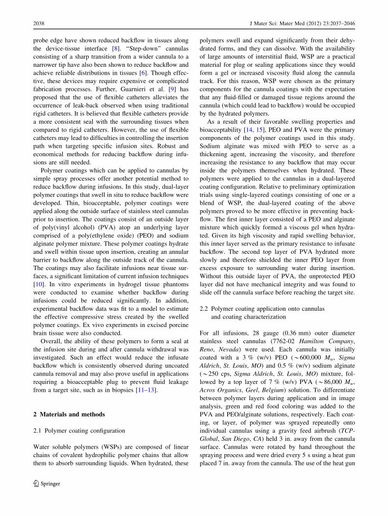
thickness of each dry polymer layer, scanning electron
microscopy was used to take images of cannulas with and
without polymer coatings (Fig. 1). The difference in
thickness between the coated and non-coated cannula was
assessed with digital image analysis via the conversion of
image pixels to microns found using the diameter of the
cannula as a known measurement reference.
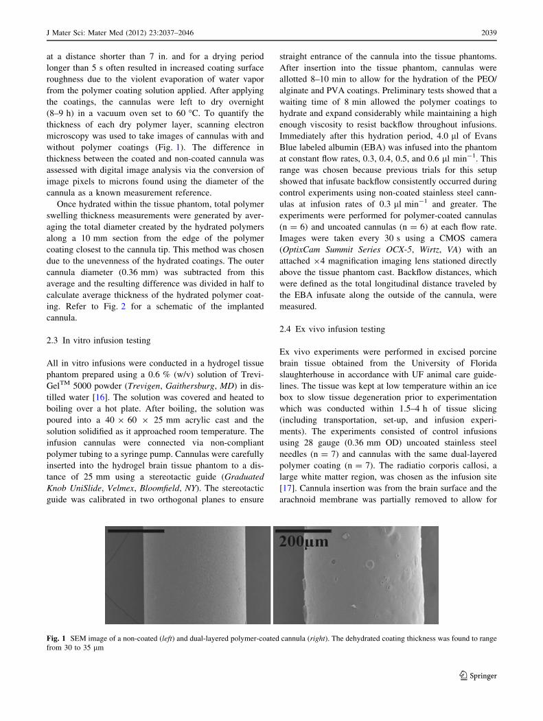
Once hydrated within the tissue phantom, total polymer
swelling thickness measurements were generated by aver-
aging the total diameter created by the hydrated polymers
along a 10 mm section from the edge of the polymer
coating closest to the cannula tip. This method was chosen
due to the unevenness of the hydrated coatings. The outer
cannula diameter (0.36 mm) was subtracted from this
average and the resulting difference was divided in half to
calculate average thickness of the hydrated polymer coat-
ing. Refer to Fig. 2 for a schematic of the implanted
cannula.
2.3 In vitro infusion testing
All in vitro infusions were conducted in a hydrogel tissue
phantom prepared using a 0.6 % (w/v) solution of Trevi-
GelTM 5000 powder (Trevigen, Gaithersburg, MD) in dis-
tilled water [16]. The solution was covered and heated to
boiling over a hot plate. After boiling, the solution was
poured into a 40 9 60 9 25 mm acrylic cast and the
solution solidified as it approached room temperature. The
infusion cannulas were connected via non-compliant
polymer tubing to a syringe pump. Cannulas were carefully
inserted into the hydrogel brain tissue phantom to a dis-
tance of 25 mm using a stereotactic guide (Graduated
Knob UniSlide, Velmex, Bloomfield, NY). The stereotactic
guide was calibrated in two orthogonal planes to ensure
straight entrance of the cannula into the tissue phantoms.
After insertion into the tissue phantom, cannulas were
allotted 8–10 min to allow for the hydration of the PEO/
alginate and PVA coatings. Preliminary tests showed that a
waiting time of 8 min allowed the polymer coatings to
hydrate and expand considerably while maintaining a high
enough viscosity to resist backflow throughout infusions.
Immediately after this hydration period, 4.0 ll of Evans
Blue labeled albumin (EBA) was infused into the phantom
at constant flow rates, 0.3, 0.4, 0.5, and 0.6 ll min-1. This
range was chosen because previous trials for this setup
showed that infusate backflow consistently occurred during
control experiments using non-coated stainless steel cann-
ulas at infusion rates of 0.3 ll min-1 and greater. The
experiments were performed for polymer-coated cannulas
(n = 6) and uncoated cannulas (n = 6) at each flow rate.
Images were taken every 30 s using a CMOS camera
(OptixCam Summit Series OCX-5, Wirtz, VA) with an
attached 94 magnification imaging lens stationed directly
above the tissue phantom cast. Backflow distances, which
were defined as the total longitudinal distance traveled by
the EBA infusate along the outside of the cannula, were
measured.
2.4 Ex vivo infusion testing
Ex vivo experiments were performed in excised porcine
brain tissue obtained from the University of Florida
slaughterhouse in accordance with UF animal care guide-
lines. The tissue was kept at low temperature within an ice
box to slow tissue degeneration prior to experimentation
which was conducted within 1.5–4 h of tissue slicing
(including transportation, set-up, and infusion experi-
ments). The experiments consisted of control infusions
using 28 gauge (0.36 mm OD) uncoated stainless steel
needles (n = 7) and cannulas with the same dual-layered
polymer coating (n = 7). The radiatio corporis callosi, a
large white matter region, was chosen as the infusion site
[17]. Cannula insertion was from the brain surface and the
arachnoid membrane was partially removed to allow for
Fig. 1 SEM image of a non-coated (left) and dual-layered polymer-coated cannula (right). The dehydrated coating thickness was found to range
from 30 to 35 lm
J Mater Sci: Mater Med (2012) 23:2037–2046 2039
123
easy insertion before all infusion experiments. The route of
the cannula was approximately in the coronal plane. Due to
the softness of brain tissue, tissue samples were also sup-
ported with 0.6 % hydrogel within an acrylic cast (*1 h to
prepare and solidify). The infusion system used was iden-
tical to that used for in vitro testing. After cannula inser-
tion, a 5–7 min waiting time was allotted and 4.0 ll EBA
was infused at a rate of 0.3 ll min-1. At the end of infu-
sion, the cannula was slowly removed from the tissue
sample. After completion of infusions, brain tissue was
sectioned *5 mm from the infusion site through a plane
parallel with the cannula to check for backflow. Backflow
distances were not quantitatively evaluated as the cannula
tip location could not be determined after the removal of
the cannula.
2.5 Residual stress estimates
A simple analytical model was also used to estimate local
polymer coating and tissue interactions which result in
compressive residual stresses surrounding the cannula and
which otherwise cannot be measured experimentally. Pre-
viously developed backflow models [7, 18] were adapted to
account for a residual stresses between the cannula and
surrounding media. Then calculated backflow distances
were compared to experimental measures (n = 6) to esti-
mate an equivalent residual stress (rr) for polymer-coated
needles. Previous backflow models considered tissue sur-
rounding a cylindrical cannula (modeled using an axi-
symmetric geometry) with tissue behaving as linear elastic
porous media. Fluid was allowed to enter between the
porous media and cannula producing a gap between the
tissue and the outer cannula wall. The flow through the gap
was considered to follow Poiseuille’s law and expansion of
the gap produced stress in the surrounding porous media. In
this study, the stress generated by the polymer swelling was
considered as a residual stress that infused fluid had to
overcome before backflow was generated. Therefore with
backflow, it was assumed that infusion pressure equals rr
in the porous media (polymer plus tissue) at the cannula
boundary. Also, the bulk of infusion was assumed to take
place along the cylindrical surface surrounding the cannula,
and the pressure along the cannula length was supposed to
be constant rather than decreasing with distance from the
cannula tip. (This assumption was based on tracer distri-
bution patterns which show approximately constant pene-
tration depths along the cannula track, see Figs. 3 and 6.)
Based on the backflow model of Morrison et al. [7], the
residual stress needed to infuse at a flow rate Q is then
given by
rr ¼Q
Z2p/kln
L
rc
� �ð½1�Þ
where Z is the backflow distance, rc is the outside radius of
the cannula, L is the characteristic length, / is the porosity,
and k is the hydraulic conductivity of the surrounding
porous media tissue. Values of L = 4 cm, k = 6 9 10-9
cm4/dyne s [18], and / = 0.6 [19] were used based on
previously reported values for hydrogel. The experimental
values of z where calculated in Eq. ([1]) for varying Q and
rr to estimate varying residual stress loading. A sensitivity
analysis was done to evaluate the influence of this preload
on the backflow distances. Residual stresses were also
estimated using the backflow model of Raghavan et al. [18]
considering rr to equal the infusate pressure at the far end
of the backflow region, and similar results were obtained.
Fig. 2 A schematic depiction of polymer swelling and backflow
distance. Polymer swelling thickness measures were made by
averaging the total diameters (Dd) of the hydrated polymers along a
10 mm section from the edge of the polymer coating closest to the
cannula tip. Measurements were taken at 1 mm intervals (Dx). The
cannula width was then subtracted from the total diameter average
and the resultant polymer-only distance was divided in half to
represent the thickness along one side (t). Backflow distances were
measured from the tip of the cannula to the leading tracer edge along
the cannula
2040 J Mater Sci: Mater Med (2012) 23:2037–2046
123
Best fit values for rr were determined using the least
squares method.
3 Results
3.1 Polymer coating measurements
For coated needles prior to insertions, the inner PEO/
alginate layer was found to range from 25 to 30 lm and the
outer PVA layer was determined to be less than 5 lm.
Before vacuum oven drying, the PEO/alginate layer was
found to have a mass of 2.34 ± 0.24 mg (n = 10) and the
mass of the PVA layer was 1.60 ± 0.23 mg (n = 10).
Since this top layer was used solely as a protective cover
for the inner coating, only a very thin coating was needed.
After drying in the vacuum oven, the total mass of the
polymer dual layer on the cannulas was reduced to
3.18 ± 0.26 mg (n = 10). After the set hydration period
during infusions, the swelling of the polymers was gener-
ally non-uniform (conforming to surrounding free spaces)
along the cannula with an average thickness of 0.37 mm
from the cannula surface (n = 10).
3.2 In vitro infusions
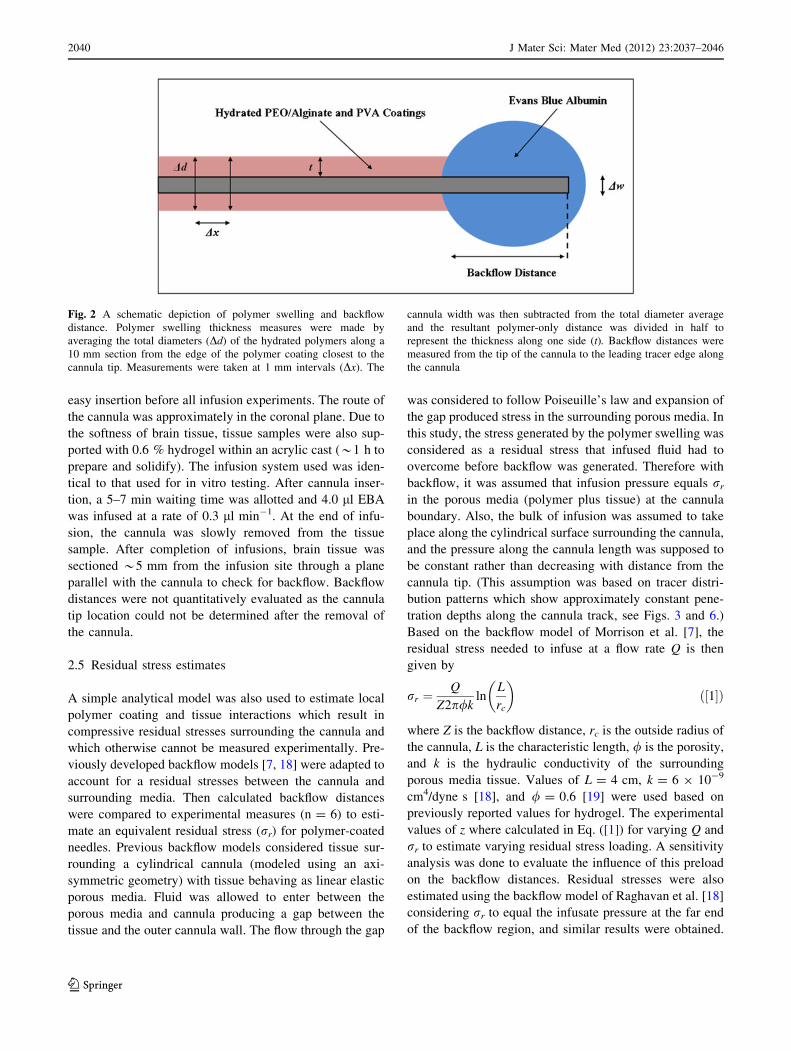
Infusions performed using uncoated cannulas consistently
had significant amounts of backflow at each infusion rate
tested. This backflow occurred immediately following the
start of infusions and reached a distance of 18 mm on
average from the tip of the cannula, resulting in little to no
spread within the target site at the tip of the cannula
(Fig. 3a). Under the same conditions, the dual-layered
polymer coating of the PEO/alginate mixture and PVA
provided more successful distributions (Fig. 3b). These
infusate distributions generally took an elliptical shape,
elongated along the major axis of the cannula in the
direction of insertion. Occasionally, distributions would
take an irregular shape, the most common of which
included a narrow leak-back, or ‘‘tail,’’ of infusate often
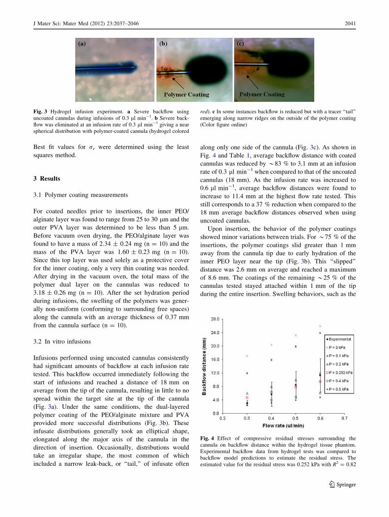
along only one side of the cannula (Fig. 3c). As shown in
Fig. 4 and Table 1, average backflow distance with coated
cannulas was reduced by *83 % to 3.1 mm at an infusion
rate of 0.3 ll min-1 when compared to that of the uncoated
cannulas (18 mm). As the infusion rate was increased to
0.6 ll min-1, average backflow distances were found to
increase to 11.4 mm at the highest flow rate tested. This
still corresponds to a 37 % reduction when compared to the
18 mm average backflow distances observed when using
uncoated cannulas.
Upon insertion, the behavior of the polymer coatings
showed minor variations between trials. For *75 % of the
insertions, the polymer coatings slid greater than 1 mm
away from the cannula tip due to early hydration of the
inner PEO layer near the tip (Fig. 3b). This ‘‘slipped’’
distance was 2.6 mm on average and reached a maximum
of 8.6 mm. The coatings of the remaining *25 % of the
cannulas tested stayed attached within 1 mm of the tip
during the entire insertion. Swelling behaviors, such as the
Fig. 3 Hydrogel infusion experiment. a Severe backflow using
uncoated cannulas during infusions of 0.3 ll min-1. b Severe back-
flow was eliminated at an infusion rate of 0.3 ll min-1 giving a near
spherical distribution with polymer-coated cannula (hydrogel colored
red). c In some instances backflow is reduced but with a tracer ‘‘tail’’
emerging along narrow ridges on the outside of the polymer coating
(Color figure online)
Fig. 4 Effect of compressive residual stresses surrounding the
cannula on backflow distance within the hydrogel tissue phantom.
Experimental backflow data from hydrogel tests was compared to
backflow model predictions to estimate the residual stress. The
estimated value for the residual stress was 0.252 kPa with R2 = 0.82
J Mater Sci: Mater Med (2012) 23:2037–2046 2041
123
time needed for hydration and the thickness upon hydra-
tion, were not affected by these slipped variations.
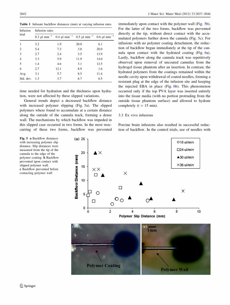
General trends depict a decreased backflow distance
with increased polymer slipping (Fig. 5a). The slipped
polymers where found to accumulate at a certain distance
along the outside of the cannula track, forming a dense
wall. The mechanisms by which backflow was impeded in
this slipped case occurred in two forms. In the most reoc-
curring of these two forms, backflow was prevented
immediately upon contact with the polymer wall (Fig. 5b).
For the latter of the two forms, backflow was prevented
directly at the tip, without direct contact with the accu-
mulated polymers further down the cannula (Fig. 5c). For
infusions with no polymer coating detachment, the reduc-
tion of backflow began immediately at the tip of the can-
nula upon contact with the hydrated coating (Fig. 6a).
Lastly, backflow along the cannula track was repetitively
observed upon removal of uncoated cannulas from the
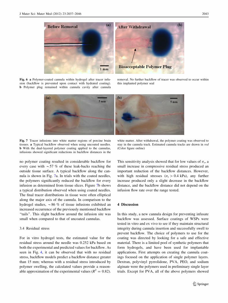
hydrogel tissue phantom after an insertion. In contrast, the
hydrated polymers from the coatings remained within the
needle cavity upon withdrawal of coated needles, forming a
resistant plug at the edge of the infusion site and keeping
the injected EBA in place (Fig. 6b). This phenomenon
occurred only if the top PVA layer was inserted entirely
into the tissue media (with no portion protruding from the
outside tissue phantom surface) and allowed to hydrate
completely (t [ 15 min).
3.3 Ex vivo infusions
Porcine brain infusions also resulted in successful reduc-
tion of backflow. In the control trials, use of needles with
Table 1 Infusate backflow distances (mm) at varying infusion rates
Infusion
trial
Infusion rates
0.3 ll min-1 0.4 ll min-1 0.5 ll min-1 0.6 ll min-1
1 3.2 1.9 20.0 6.1
2 5.4 7.3 3.8 20.0
3 2.7 2.4 3.5 13.9
4 3.3 5.9 11.9 14.0
5 1.4 4.6 3.1 12.5
6 2.7 12.1 8.9 1.6
Avg. 3.1 5.7 8.5 11.4
Std. dev. 1.3 3.7 6.7 6.5
Fig. 5 a Backflow distances
with increasing polymer slip
distance. Slip distances were
measured from the tip of the
cannula to the edge of the
polymer coating. b Backflow
prevented upon contact with
slipped polymer wall.
c Backflow prevented before
contacting polymer wall
2042 J Mater Sci: Mater Med (2012) 23:2037–2046
123
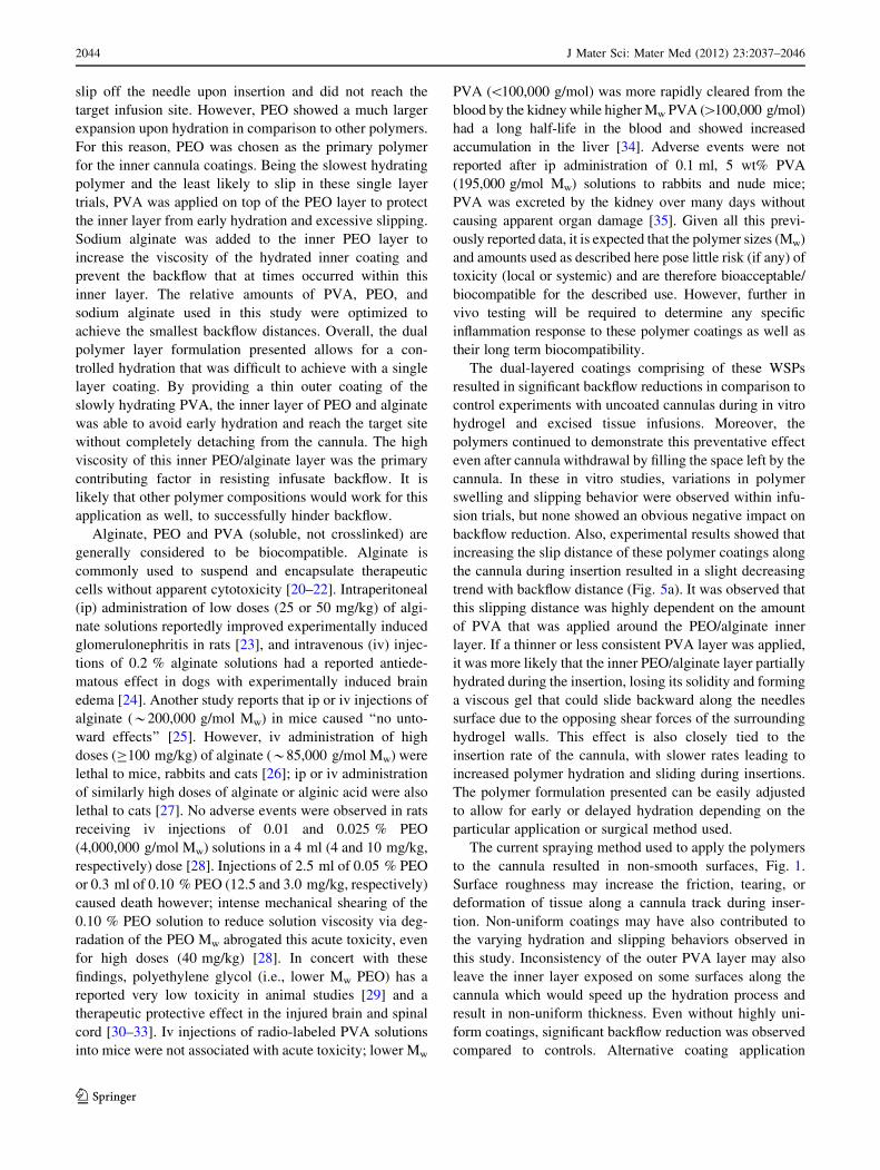
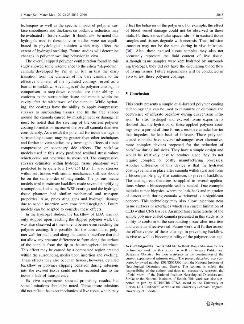
no polymer coating resulted in considerable backflow for
every case with *57 % of these leak-backs reaching the
outside tissue surface. A typical backflow along the can-
nula is shown in Fig. 7a. In trials with the coated needles,
the polymers significantly reduced the backflow for every
infusion as determined from tissue slices. Figure 7b shows
a typical distribution observed when using coated needles.
The final tracer distributions in tissue were often elliptical
along the major axis of the cannula. In comparison to the
hydrogel studies, *86 % of tissue infusions exhibited an
increased occurrence of the previously mentioned backflow
‘‘tails’’. This slight backflow around the infusion site was
small when compared to that of uncoated cannulas.
3.4 Residual stress
For in vitro hydrogel tests, the estimated value for the
residual stress around the needle was 0.252 kPa based on
both the experimental and predicted values for backflow. As
seen in Fig. 4, it can be observed that with no residual
stress, backflow models predict a backflow distance greater
than 15 mm; whereas with a residual stress introduced by
polymer swelling, the calculated values provide a reason-
able approximation of the experimental values (R2 = 0.82).
This sensitivity analysis showed that for low values of rr, a
small increase in compressive residual stress produced an
important reduction of the backflow distances. However,
with high residual stresses (rr [ 0.4 kPa), any further
increase produced only a slight decrease in the backflow
distance, and the backflow distance did not depend on the
infusion flow rate over the range tested.
4 Discussion
In this study, a new cannula design for preventing infusate
backflow was assessed. Surface coatings of WSPs were
tested in vitro and ex vivo to see if they maintain structural
integrity during cannula insertion and successfully swell to
prevent backflow. The choice of polymers to use for the
coating was directed by looking for a safe and effective
material. There is a limited pool of synthetic polymers that
form hydrogels, and have been used for implantable
applications. First attempts on creating the cannula coat-
ings focused on the application of single polymer layers.
Dextran, polyvinyl pyrrolidone, PVA, PEO, and sodium
alginate were the polymers used in preliminary single layer
trials. Except for PVA, all of the above polymers showed
Fig. 6 a Polymer-coated cannula within hydrogel after tracer infu-
sion (backflow is prevented upon contact with hydrated coating).
b Polymer plug remained within cannula cavity after cannula
removal. No further backflow of tracer was observed to occur within
this implanted polymer seal
Fig. 7 Tracer infusions into white matter regions of porcine brain
tissues. a Typical backflow observed when using uncoated needles.
b With the dual-layered polymer coating applied to the cannulas,
infusions showed significant reductions in backflow distances in the
white matter. After withdrawal, the polymer coating was observed to
stay in the cannula track. Estimated cannula tracks are drawn in red(Color figure online)
J Mater Sci: Mater Med (2012) 23:2037–2046 2043
123
slip off the needle upon insertion and did not reach the
target infusion site. However, PEO showed a much larger
expansion upon hydration in comparison to other polymers.
For this reason, PEO was chosen as the primary polymer
for the inner cannula coatings. Being the slowest hydrating
polymer and the least likely to slip in these single layer
trials, PVA was applied on top of the PEO layer to protect
the inner layer from early hydration and excessive slipping.
Sodium alginate was added to the inner PEO layer to
increase the viscosity of the hydrated inner coating and
prevent the backflow that at times occurred within this
inner layer. The relative amounts of PVA, PEO, and
sodium alginate used in this study were optimized to
achieve the smallest backflow distances. Overall, the dual
polymer layer formulation presented allows for a con-
trolled hydration that was difficult to achieve with a single
layer coating. By providing a thin outer coating of the
slowly hydrating PVA, the inner layer of PEO and alginate
was able to avoid early hydration and reach the target site
without completely detaching from the cannula. The high
viscosity of this inner PEO/alginate layer was the primary
contributing factor in resisting infusate backflow. It is
likely that other polymer compositions would work for this
application as well, to successfully hinder backflow.
Alginate, PEO and PVA (soluble, not crosslinked) are
generally considered to be biocompatible. Alginate is
commonly used to suspend and encapsulate therapeutic
cells without apparent cytotoxicity [20–22]. Intraperitoneal
(ip) administration of low doses (25 or 50 mg/kg) of algi-
nate solutions reportedly improved experimentally induced
glomerulonephritis in rats [23], and intravenous (iv) injec-
tions of 0.2 % alginate solutions had a reported antiede-
matous effect in dogs with experimentally induced brain
edema [24]. Another study reports that ip or iv injections of
alginate (*200,000 g/mol Mw) in mice caused ‘‘no unto-
ward effects’’ [25]. However, iv administration of high
doses (C100 mg/kg) of alginate (*85,000 g/mol Mw) were
lethal to mice, rabbits and cats [26]; ip or iv administration
of similarly high doses of alginate or alginic acid were also
lethal to cats [27]. No adverse events were observed in rats
receiving iv injections of 0.01 and 0.025 % PEO
(4,000,000 g/mol Mw) solutions in a 4 ml (4 and 10 mg/kg,
respectively) dose [28]. Injections of 2.5 ml of 0.05 % PEO
or 0.3 ml of 0.10 % PEO (12.5 and 3.0 mg/kg, respectively)
caused death however; intense mechanical shearing of the
0.10 % PEO solution to reduce solution viscosity via deg-
radation of the PEO Mw abrogated this acute toxicity, even
for high doses (40 mg/kg) [28]. In concert with these
findings, polyethylene glycol (i.e., lower Mw PEO) has a
reported very low toxicity in animal studies [29] and a
therapeutic protective effect in the injured brain and spinal
cord [30–33]. Iv injections of radio-labeled PVA solutions
into mice were not associated with acute toxicity; lower Mw
PVA (\100,000 g/mol) was more rapidly cleared from the
blood by the kidney while higher Mw PVA ([100,000 g/mol)
had a long half-life in the blood and showed increased
accumulation in the liver [34]. Adverse events were not
reported after ip administration of 0.1 ml, 5 wt% PVA
(195,000 g/mol Mw) solutions to rabbits and nude mice;
PVA was excreted by the kidney over many days without
causing apparent organ damage [35]. Given all this previ-
ously reported data, it is expected that the polymer sizes (Mw)
and amounts used as described here pose little risk (if any) of
toxicity (local or systemic) and are therefore bioacceptable/
biocompatible for the described use. However, further in
vivo testing will be required to determine any specific
inflammation response to these polymer coatings as well as
their long term biocompatibility.
The dual-layered coatings comprising of these WSPs
resulted in significant backflow reductions in comparison to
control experiments with uncoated cannulas during in vitro
hydrogel and excised tissue infusions. Moreover, the
polymers continued to demonstrate this preventative effect
even after cannula withdrawal by filling the space left by the
cannula. In these in vitro studies, variations in polymer
swelling and slipping behavior were observed within infu-
sion trials, but none showed an obvious negative impact on
backflow reduction. Also, experimental results showed that
increasing the slip distance of these polymer coatings along
the cannula during insertion resulted in a slight decreasing
trend with backflow distance (Fig. 5a). It was observed that
this slipping distance was highly dependent on the amount
of PVA that was applied around the PEO/alginate inner
layer. If a thinner or less consistent PVA layer was applied,
it was more likely that the inner PEO/alginate layer partially
hydrated during the insertion, losing its solidity and forming
a viscous gel that could slide backward along the needles
surface due to the opposing shear forces of the surrounding
hydrogel walls. This effect is also closely tied to the
insertion rate of the cannula, with slower rates leading to
increased polymer hydration and sliding during insertions.
The polymer formulation presented can be easily adjusted
to allow for early or delayed hydration depending on the
particular application or surgical method used.
The current spraying method used to apply the polymers
to the cannula resulted in non-smooth surfaces, Fig. 1.
Surface roughness may increase the friction, tearing, or
deformation of tissue along a cannula track during inser-
tion. Non-uniform coatings may have also contributed to
the varying hydration and slipping behaviors observed in
this study. Inconsistency of the outer PVA layer may also
leave the inner layer exposed on some surfaces along the
cannula which would speed up the hydration process and
result in non-uniform thickness. Even without highly uni-
form coatings, significant backflow reduction was observed
compared to controls. Alternative coating application
2044 J Mater Sci: Mater Med (2012) 23:2037–2046
123
techniques as well as the specific impact of polymer sur-
face smoothness and thickness on backflow reduction may
be evaluated in future studies. It should also be noted that
hydrogels used in these in vitro studies were not equili-
brated in physiological solution which may affect the
extent of hydrogel swelling. Future studies will determine
changes in polymer swelling behavior in vivo.
The overall slipped polymer configuration found in this
study showed some resemblance to the silica ‘‘step-down’’
cannula developed by Yin et al. [6], in that the sharp
transition from the diameter of the bare cannula to the
effective diameter of the hydrated coatings served as a
barrier to backflow. Advantages of the polymer coatings in
comparison to step-down cannulas are their ability to
conform to the surrounding tissue and remain within the
cavity after the withdrawal of the cannula. While hydrat-
ing, the coatings have the ability to apply compressive
stresses to surrounding tissues and fill the free spaces
around the cannula caused by misalignment or damage. It
must be noted that the swelling of the current polymer
coating formulation increased the overall cannula diameter
considerably. As a result the potential for tissue damage in
surrounding tissues may be greater than other techniques
and further in vivo studies may investigate effects of tissue
compression on secondary side effects. The backflow
models used in this study predicted residual stress values
which could not otherwise be measured. The compressive
stresses estimates within hydrogel tissue phantoms were
predicted to be quite low (*0.754 kPa). In vivo stresses
within soft tissues with similar mechanical stiffness should
be on the same order of magnitude. The porous media
models used to estimate backflow made several simplifying
assumptions, including that WSP coatings and the hydrogel
tissue phantom had similar mechanical and transport
properties. Also, preexisting gaps and hydrogel damage
due to needle insertion were considered negligible. Future
models can be adapted to consider these effects.
In the hydrogel studies, the backflow of EBA was not
only stopped upon reaching the slipped polymer wall, but
was also observed at times to end before even reaching the
polymer coating. It is possible that the accumulated poly-
mer wall formed a seal along the cannula interface that did
not allow any pressure difference to form along the surface
of the cannula from the tip to the atmospheric interface.
This effect may be caused by a compacted region created
within the surrounding media upon insertion and swelling.
These effects may also occur in tissues, however, detailed
backflow or polymer slipping behavior during infusions
into the excised tissue could not be recorded due to the
tissue’s lack of transparency.
Ex vivo experiments showed promising results, but
some limitations should be noted. These tissue infusions
did not reflect the exact mechanics of live tissue which may
affect the behavior of the polymers. For example, the effect
of blood vessel damage could not be observed in these
trials. Further, extracellular spaces shrink in excised tissue
samples and tissues degrade with necrosis. Thus, infusion
transport may not be the same during in vivo infusions
[36]. Also, these excised tissue samples may also not
accurately represent the fluid content of live tissue.
Although tissue samples were kept hydrated by surround-
ing hydrogel, they did not have the circulating blood flow
of living tissues. Future experiments will be conducted in
vivo to test these polymer coatings.
5 Conclusion
This study presents a simple dual-layered polymer coating
technology that can be used to minimize or eliminate the
occurrence of infusate backflow during direct tissue infu-
sion. In vitro hydrogel and excised tissue experiments
showed that the hydration of these applied polymer coat-
ings over a period of time forms a resistive annular barrier
that impedes the leak-back of infusate. These polymer-
coated cannulas have several advantages over alternative,
more complex devices proposed for the reduction of
backflow during infusions. They have a simple design and
would be relatively easy to produce since they do not
require complex or costly manufacturing processes.
Another difference of this device is that the hydrated
coatings remain in place after cannula withdrawal and form
a biocompatible plug that continues to prevent backflow.
The coatings can therefore be applied to several applica-
tions where a bioacceptable seal is needed. One example
includes tumor biopsies, where the leak-back and migration
of cancer cells during cannula withdrawal is a significant
concern. This technology may also allow injections near
tissue surfaces or interfaces which is a current limitation of
CED within CNS tissues. An important characteristic of the
simple polymer-coated cannula presented in this study is its
ability to conform to the surrounding tissue after insertion
and create an effective seal. Future work will further assess
the effectiveness of these coatings in preventing backflow
in vivo as well as biocompatibility of the polymer coatings.
Acknowledgments We would like to thank Ronja Mansson for her
preliminary work on this project as well as Gregory Pishko and
Benjamin Oberstein for their assistance in the construction of the
current experimental infusion setup. The project described was sup-
ported by award number R01NS063360 from the National Institute of
Neurological Disorders and Stroke. The content is solely the
responsibility of the authors and does not necessarily represent the
official views of the National Institute Neurological Disorders and
Stroke or the National Institutes of Health. This work was also sup-
ported in part by NIH/NCRR CTSA award to the University of
Florida UL1 RR029890, as well as the University Scholars Program,
University of Florida.
J Mater Sci: Mater Med (2012) 23:2037–2046 2045
123
References
1. Bobo RH, Laske DW, Akbasak A, Morrison PF, Dedrick RL,
Oldfield EH. Convection-enhanced delivery of macromolecules
in the brain. Proc Natl Acad Sci USA. 1994;91(6):2076–80.
2. Gill SS, Patel NK, Hotton GR, O’Sullivan K, McCarter R,
Bunnage M, et al. Direct brain infusion of glial cell line-derived
neurotrophic factor in Parkinson disease. Nat Med. 2003;9(5):
589–95.
3. Rogawski MA. Convection-enhanced delivery in the treatment of
epilepsy. Neurotherapeutics. 2009;6(2):344–51.
4. Sampson JH, Brady ML, Petry NA, Croteau D, Friedman AH,
Friedman HS, et al. Intracerebral infusate distribution by con-
vection-enhanced delivery in humans with malignant gliomas:
descriptive effects of target anatomy and catheter positioning.
Neurosurgery. 2007;60(2):89–98.
5. Chen MY, Lonser RR, Morrison PF, Governale LS, Oldfield EH.
Variables affecting convection-enhanced delivery to the striatum:
a systematic examination of rate of infusion, cannula size, infu-
sate concentration, and tissue-cannula sealing time. J Neurosurg.
1999;90(2):315–20.
6. Yin D, Forsayeth J, Bankiewicz KS. Optimized cannula design
and placement for convection-enhanced delivery in rat striatum.
J Neurosci Methods. 2010;187(1):46–51.
7. Morrison PF, Chen MY, Chadwick RS, Lonser RR, Oldfield EH.
Focal delivery during direct infusion to brain: role of flow rate,
catheter diameter, and tissue mechanics (vol 277, pg R1218,
1999). Am J Physiol Regul Integr Comp Physiol. 2002;282(6):
R1218–R1229.
8. Neeves KB, Lo CT, Foley CP, Saltzman WM, Olbricht WL.
Fabrication and characterization of microfluidic probes for con-
vection enhanced drug delivery. J Control Release. 2006;111(3):
252–62.
9. Guarnieri M, Carson BS, Khan A, Penno M, Jallo GI. Flexible
versus rigid catheters for chronic administration of exogenous
agents into central nervous system tissues. J Neurosci Methods.
2005;144(2):147–52.
10. Jagannathan J, Walbridge S, Butman JA, Oldfield EH, Lonser
RR. Effect of ependymal and pial surfaces on convection-
enhanced delivery. Laboratory investigation. J Neurosurg. 2008;
109(3):547–52.
11. Cho MH, Malhotra A, Donahue DM, Wain JC, Harris RS,
Karmpaliotis D, et al. Mechanical ventilation and air leaks after
lung biopsy for acute respiratory distress syndrome. Ann Thorac
Surg. 2006;82(1):261–7.
12. Kelley ML, Mosenthal WT, Milne J. Bile leakage following
menghini needle liver biopsy. J Am Med Assoc. 1971;216(2):
333–333(1).
13. Wiksell H, Schassburger KU, Janicijevic M, Leifland K, Lofgren
L, Rotstein S, et al. Prevention of tumour cell dissemination in
diagnostic needle procedures. Br J Cancer. 2010;103(11):1706–9.
14. Bjugstad KB, Lampe K, Kern DS, Mahoney M. Biocompatibility
of poly(ethylene glycol)-based hydrogels in the brain: an analysis
of the glial response across space and time. J Biomed Mater Res
A. 2010;95A(1):79–91.
15. Jiang YJ, Schadlich A, Amado E, Weis C, Odermatt E, Mader K,
et al. In vivo studies on intraperitoneally administrated poly(vinyl
alcohol). J Biomed Mater Res B. 2010;93B(1):275–84.
16. Chen ZJ, Gillies GT, Broaddus WC, Prabhu SS, Fillmore H,
Mitchell RM, et al. A realistic brain tissue phantom for intrapa-
renchymal infusion studies. J Neurosurg. 2004;101(2):314–22.
17. Felix B, Leger ME, Albe-Fessard D. Stereotaxic atlas of the pig
brain. Brain Res Bull. 1999;49(1–2):1–137.
18. Raghavan R, Mikaelian S, Brady M, Chen ZJ. Fluid infusions
from catheters into elastic tissue: I. Azimuthally symmetric
backflow in homogeneous media. Phys Med Biol. 2010;55(1):
281–304.
19. Chen XM, Astary GW, Sepulveda H, Mareci TH, Sarntinoranont
M. Quantitative assessment of macromolecular concentration
during direct infusion into an agarose hydrogel phantom using
contrast-enhanced MRI. Magn Reson Imaging. 2008;26(10):
1433–41.
20. Lim F, Sun AM. Microencapsulated islets as bioartificial endo-
crine pancreas. Science. 1980;210(4472):908–10.
21. Soonshiong P, Feldman E, Nelson R, Heintz R, Yao Q, Yao ZW,
et al. Long-term reversal of diabetes by the injection of immu-
noprotected islets. Proc Natl Acad Sci USA. 1993;90(12):5843–7.
22. Soonshiong P, Heintz RE, Merideth N, Yao QX, Yao ZW, Zheng
TL, et al. Insulin independence in a type-1 diabetic patient after
encapsulated islet transplantation. Lancet. 1994;343(8903):950–1.
23. Mirshafiey A, Borzooy Z, Abhari RS, Razavi A, Tavangar M,
Rehm BHA. Treatment of experimental immune complex glo-
merulonephritis by sodium alginate. Vasc Pharmacol. 2005;
43(1):30–5.
24. Lavrov VP. The experimental treatment of acute edema of the
brain with sodium alginate From: Ref Zh Otd Vypusk Farmakol
Toksikol, 1964, no. 22.54.98 (translation). Sb Nauch Tr Vladi
Vostokskh Med Inst. 1964;2(1):9–10.
25. Hagen A, Skjak-Braek G, Dornish M. Pharmacokinetics of
sodium alginate in mice. Eur J Pharm Sci. 1996;4(Suppl):
100–100(1).
26. Solandt OM. Some observations upon sodium alginate. Q J Exp
Physiol Cogn Med Sci. 1942;31:25–30.
27. Chenoweth MB. The toxicity of sodium alginate in cats. Ann
Surg. 1948;127(6):1173–81.
28. Smyth HF, Weil CS, Woodside MD, Knaak JB, Sullivan LJ,
Carpente CP. Experimental toxicity of a high molecular
weight poly(ethylene oxide). Toxicol Appl Pharmacol. 1970;16(2):
442–445.
29. Fruijtier-Polloth C. Safety assessment on polyethylene glycols
(PEGs) and their derivatives as used in cosmetic products. Tox-
icology. 2005;214(1–2):1–38.
30. Borgens RB, Shi R. Immediate recovery from spinal cord injury
through molecular repair of nerve membranes with polyethylene
glycol. FASEB J. 2000;14(1):27–35.
31. Shi R, Borgens RB. Acute repair of crushed guinea pig spinal cord
by polyethylene glycol. J Neurophysiol. 1999;81(5):2406–14.
32. Shi R, Borgens RB. Anatomical repair of nerve membranes in
crushed mammalian spinal cord with polyethylene glycol.
J Neurocytol. 2000;29(9):633–43.
33. Smucker P, Hekmatyar SK, Bansal N, Rodgers RB, Shapiro SA,
Borgens RB. Intravenous polyethylene glycol successfully treats
severe acceleration-induced brain injury in rats as assessed by
magnetic resonance imaging. Neurosurgery. 2009;64(5):984–90.
34. Tabata T, Murakami Y, Ikada Y. Tumor accumulation of poly(-
vinyl alcohol) of different sizes after intravenous injection.
J Control Release. 1998;50(1–3):123–33.
35. Jiang YJ, Schadlich A, Amado E, Weis C, Odermatt E, Mader K,
et al. In vivo studies on intraperitoneally administrated poly(vinyl
alcohol). J Biomed Mater Res B. 2010;93B(1):275–84.
36. Nicholson C, Sykova E. Extracellular space structure revealed by
diffusion analysis. Trends Neurosci. 1998;21(5):207–15.
2046 J Mater Sci: Mater Med (2012) 23:2037–2046
123