Embed Size (px)
Citation preview

Displays 34 (2013) 1–7
Contents lists available at SciVerse ScienceDirect
Displays
journal homepage: www.elsevier .com/locate /displa
Polyaniline: Application as solid state electrochromic in a flexible textile display
Fern M. Kelly ⇑, Ludivine Meunier, Cédric Cochrane, Vladan KoncarUniv Lille Nord de France, F-59000 Lille, FranceENSAIT, GEMTEX, F-59100 Roubaix, France
a r t i c l e i n f o
Article history:Received 6 March 2012Received in revised form 19 July 2012Accepted 4 October 2012Available online 12 October 2012
Keywords:CompositeElectrochromicFlexible displayPolyanilineSandwich structureSpacer textile
0141-9382/$ - see front matter � 2012 Elsevier B.V. Ahttp://dx.doi.org/10.1016/j.displa.2012.10.001
⇑ Corresponding author at: ENSAIT, GEMTEX, 2 alléBP 30329, 59056 ROUBAIX Cedex 1, France. Tel.: +33
E-mail address: [email protected] (F.M. Kelly).
a b s t r a c t
A composite of polyaniline with a flexible nonwoven textile spacer (viscose or PET) has been successfullyprepared. Aniline monomer units were initially bound to the surface of the nonwoven substrate and sub-sequently chemically polymerised in its solid state. The prepared composite was then employed within aflexible four-layer electrochromic device (ECD), previously developed by ourselves. The device consists ofthe polyaniline–nonwoven composite sandwiched between two electrodes. The lower electrode is silveror carbon black deposited on a flexible PET textile substrate and the upper is flexible and transparent PET/ITO. A reversible colour change of the polyaniline–nonwoven composite is observed, from green to blue,when an electrical voltage (±3 V) is applied to the prepared device. Because polyaniline is used in its solidstate it offers an alternative to the liquid state electrochromic previously applied within the developedflexible textile ECD and reduces problems owing to satisfactory sealing and leakage. This paper outlinesthe preparation and characterisation of the electrochromic polyaniline–nonwoven composite and theelectrochromic display prototype in which it is applied. The benefits and drawbacks of the technologyare discussed.
� 2012 Elsevier B.V. All rights reserved.
1. Introduction
Chromic materials are those materials that can reversiblychange their colour when an external stimulus is applied. The typeof stimuli that induces the colour change determines the chromicclassification. For example, ‘‘photochromic’’ and ‘‘thermochromic’’materials see a change in colour when there is a change in light,or a change in heat, respectively [1–3]. Conversely, ‘‘electrochro-mic’’ materials are those that exhibit a reversible colour changewhen an external voltage is applied. Both photochromic and ther-mochromic materials have seen applications within textile fields,predominantly within fashion and interior furnishings. Availablethermochromic products include wallpapers which when heatedby nearby radiators ‘grow’ flower buds across a vine, and photo-chromic products include pillow covers which reveal a motif whenexposed to sunlight. When the heat and sunlight is removed, theflowers and motif disappear. Photochromics, when applied to tex-tiles also have the potential application in solar protection throughthe monitoring of UV radiation [4].
As with the photochromic and thermochromic materials, elec-trochromics are also currently attracting much interest in acade-mia and industry for their fascinating spectroelectrochemicalproperties and their commercial applications [5]. Products avail-
ll rights reserved.
e Louise et Victor Champier,602125274.
able include glass windows of buildings and automobiles whichdarken reversibly at the flick of a switch, re-usable price labels,camouflage materials and controllable light reflective or light-transmissive displays for optical information and storage [6–15].However, the products discussed above are typically rigid in theirstructure due to glass commonly being applied as the base sub-strate and flexible textiles treated with electrochomics are notreadily available in the commercial market. Therefore, an opportu-nity exists to combine the desired spectrochemical properties ofelectrochromic materials with a flexible textile substrate. Thiswould give rise to a technology that could be applied to a suiteof flexible products that would have the ability to change its pat-tern or print. Communicative flags, clothing and interior furnish-ings, including upholstery and drapery, could therefore be created.
A number of academic and commercial research groups havebeen working on the development of ECDs that are flexible[3,16–25]. Typically plastic substrates have been utilised in orderto achieve flexibility, not textiles. Conversely, a flexible PET fabrictextile substrate has been applied in a four-layer flexible ECD pro-totype, developed by ourselves (Fig. 1). A Prussian Blue solutionhas been suspended within a nonwoven spacer fabric, with a flex-ible PET/ITO film completing the device.[26] Here, Prussian Blueacts as both electrochromic ink and electrolyte. Because it is in aliquid form it is mobile within the spacer and therefore reducesthe traditional seven-layered structure to four. Challenges existhowever when using a solution phase electrochromic material ina flexible display. As the applications for flexible displays often

Fig. 1. Four-layer sandwich structure of the flexible electrochromic displayprototype.
2 F.M. Kelly et al. / Displays 34 (2013) 1–7
require the device to be in the vertical position, i.e. flags, curtains,etc., issues include providing sufficient sealing of the device so asto ensure the retention of the electrochromic solution within thedisplay with movements of tilting and flexing.
In this paper we offer an alternative to the solution phase elec-trochromic originally used in the flexible textile four-layered ECDprototype, in order to reduce the correlated problems. Polyaniline(PAn) is used as a solid state electrochromic in place of the PrussianBlue solution. PAn has been bound to a nonwoven (NW) spacerfabric (either polyethylene terephthalate (PET) or viscose based)via an in situ electrochemical polymerisation [27], with the result-ing NW–PAn composite being implemented within the novelfour-layer electrochromic display system. Polyaniline (PAn) is aconducting polymer well known for its electrochromic propertiesdue to it having a backbone consisting of alternating single/doublebonds. The PAn structure is able to undergo reversible oxidationand reduction reactions, allowing it to alternate from neutral (insu-lating) to oxidized (conducting) forms. The change in redox state isaccompanied by a change in the absorption characteristics of thematerial, which means that their coloured states are altered whenthey alter their redox states. The physical and chemical character-istics of the prepared NW–PAn composites are provided and thebenefits and disadvantages of the developed flexible ECDdiscussed.
Table 1Physical characteristics and CIE colour scale values of untreated PET and viscosenonwovens.
Grammage(g m�2)
Thickness(mm)
Porosity L� a� b�
PET 230 0.99 84.2 90.39 0.67 �5.57Viscose 433 2.35 87.7 95.30 0.48 2.89
2. Materials and methods
2.1. Reagents and equipment
Aniline (>95%), sodium dodecyl sulfate (>98.5%), iron(III) chlo-ride hexahydrate (97%) and nonaqueous LiCl in ethanol (saturated)electrolyte solution, were all purchased from Sigma–Aldrich Chem-icals and of analytical grade. The two nonwovens employed con-sisted of 85% viscose/15% polyester and 100% polyesterrespectively and were prepared in the GEMTEX laboratory of EN-SAIT. Polyurethane-coated polyester was provided by Mediama.Carbon black and silver was purchased from Dupont de Nemours.PET/ITO films, with a surface conductivity of 3.5 � 107 S cm�1,were purchased from Sigma–Aldrich.
2.2. Preparation of nonwoven–polyaniline composites
NW–PAn composites were prepared following a method c.f. tothat developed by Kelly et al. [27] Squares of NW (5 cm2) weresoaked in a solution of aniline monomer (0.5 M) and p-dodecylben-zylsulfonate (0.05 M) in water. Stirring for approximately 1 h al-lowed for the monomer to be absorbed onto the surface of thenonwoven textile fibres. Then NW squares were filtered andwashed with further monomer solution (0.5 M, 100 cm3) andadded to the oxidant, ferric chloride (0.5 M, 100 cm3). Polymerisa-tion ensued, noted by a change in colour from orange to dark greenover a time period of approximately 15 min. However, the solutionwas left for 1, 3 or 24 h to ensure complete polymerisation and toallow for comparison. The hybrid fibres were removed from theoxidant and then washed with hydrochloric acid (1.0 M), to effect
doping with both H+ and Cl� ions, followed by further washingwith minimal water. The resulting fibres were air-dried to givesquares of NW whereby each individual fibre was coated with PAn.
2.3. Preparation of electrochromic display
The four-layer structure of Fig. 1 was retained in the construc-tion of the electrochromic display incorporating the NW–PAn com-posite. The electrochromic solution of Prussian Blue, suspendedwithin the NW spacer, was replaced instead with solid PAn, chem-ically bound to it. Polyester, pre-coated with polyurethane, to pro-vide a waterproof surface, was implemented as the base textilesubstrate. The first conductive layer, typically carbon black or sil-ver, was then applied to this via screen-printing. The NW–PAncomposite, soaked in a saturated lithium chloride electrolyte solu-tion for 15 min, was then placed upon the now conductive textilesubstrate. The device was sealed by joining the upper electrode(transparent and flexible PET/ITO) to the textile substrate usingcommercially available glue. The electrochromic display was oper-ated by the application of a voltage from a TTi 1906 ComputingMultimeter of ±3.0 V for 2 min each.
2.4. Characterisation
The morphology of the viscose and PET NWs and their PAn com-posite counterparts were characterised utilising an ULTRA 55 byZEISS scanning electron microscope (SEM). The redox propertiesof the conducting polymer/fibre composites were measured bycyclic voltammetry using Voltalab 40, consisting of a PGZ301Potentiostat with VoltaMaster 4 Electrochemical Software applied.SEM and cyclic voltammetry were both undertaken at Institutd’Electronique, de Microélectronique et de Nanotechnologie(IEMN), Université Lille 1. UV–vis spectra and CIE L�, a�, b� colourvalues were obtained via a DATACOLOR International, SpectraflashSF600 plus spectrophotometer. Conductivity measurements wereundertaken on a Keithley 617 Programmable Electrometer. A vari-able voltage (from x to y) was applied across each sample and theresultant current (I) measured.
3. Results and discussion
3.1. Physical characterisation and morphology
The physical properties and CIE colour scale L�, a�, b� values ofthe original untreated PET and viscose NW materials are offeredin Table 1. PET and viscose NWs are both white/off-white in colourin their untreated form. L� values (100 is white, 0 is black) are highfor PET and viscose confirming a high whiteness and a� values (+veis red, �ve is green) are approximately zero indicating no red orgreen hues. The b� values (+ve is yellow, �ve is blue) suggest amore blue–white for PET and a yellow–white for viscose. On treat-ment of each of the PET and viscose samples with the anilinemonomer, followed by oxidation with ferric chloride, the resultingproduct is green in colour, indicating PAn is in the emeraldine saltform. By increasing the polymerisation time from 1 to 3 to 24 h theNW–PAn’s intensity of green colour increases. The increase in

Fig. 2. UV–vis spectra for (a) PET–PAn and (b) Vis–PAn at varying polymerization times.
Table 2CIE colour scales values and weight gains of prepared nonwoven–PAn composites.
Polymerisationtime
PET–PAn Viscose–PAn
1 h 3 h 24 h 1 h 3 h 24 h
L� 42.45 36.48 33.90 36.34 28.24 20.33a� �9.38 �10.11 �10.60 �9.07 �10.40 �11.64b� 9.83 6.94 4.30 13.04 9.36 3.93Weight gain (g) 0.01 0.02 0.03 0.06 0.12 0.15% Weight gain 1.2 3.4 4.5 5.3 9.6 13.6
Fig. 3. Untreated nonwovens: (a) PET and (b) viscose.
F.M. Kelly et al. / Displays 34 (2013) 1–7 3
green was measured by UV–vis (Fig. 2) and CIE L�, a�, b� values(Table 2).
According to the literature, PAn in the green emeraldine saltform, shows three absorption bands in the UV–vis range. The p–p� transition yields an absorption band at ca. 330 nm, the p–polar-on transition at ca. 430 nm, whilst the p�–polaron gives a signal atca. 800 nm.[28] The peak corresponding to the p–polaron transi-tion at ca. 430 nm, for both PET–PAn and viscose–PAn composites,becomes increasingly stronger with increasing time periods spentwithin the oxidant solution (Fig. 2). This is due to the increasedtime available to oxidise and polymerise an increased level of ani-line monomers to PAn.
The increase in PAn within the NWs is confirmed by the %weight gains of the samples increasing from 1.2% to 2.5% and5.3% to 13.6% for PET–PAn and viscose–PAn composites respec-tively (Table 2). The quantity of fibres per square metre and theporosity of the viscose nonwoven composites are greater than thatof PET (Table 1). Hence, the overall surface area of viscose availablefor aniline monomer absorption, per square unit, is greater. Inaddition, the surface roughness of the fibre and the cellulose struc-ture of viscose has a more favourable interaction with anilinemonomer units to that of PET, therefore contributing to the greater% weight increase due to PAn formation.
With increasing polymerisation times, CIE colour scale valuesadditionally show the intensification in green colour. The mea-sured a� values become more negative, the b� values become moreclose to zero, and the L� values decrease in number (Table 2). Itshould be noted that the colour of the NW–PAn composites is re-tained with washing and subjection to ultrasonic vibration. Thisindicates that PAn is bound to the NW fibres. The bond betweenNW and PAn will be discussed in further detail in the sectionsrelating to cyclic voltammetry.
SEM images of the untreated PET and viscose fibres are offeredin Fig. 3. Fibre diameters of approximately 20 and 15 lm are ob-served for PET and viscose respectively. The higher density of pack-ing of fibres within the viscose NW (Fig. 3b) compared to the PETanalogue (Fig. 3a) is also indicated. Figs. 4 and 5 provide SEMimages of PET and viscose composites with PAn, comparing thePAn coating formed with 1, 3 and 24 h polymerisation times. PET

Fig. 4. PET–PAn composites prepared using: (a) 1 h; (b) 3 h; and (c) 24 hpolymerization times.
Fig. 5. Viscose–PAn composites prepared using: (a) 1 h; (b) 3 h; and (c) 24 hpolymerization times.
4 F.M. Kelly et al. / Displays 34 (2013) 1–7
fibres are round in form (Fig. 4), whereas viscose fibres appear toconsist of many fine fibres fused together in a parallel manner(Fig. 5). With 1 h polymerisation, a very fine but complete coatingof PAn is noted on the surface of PET and viscose fibres. As thepolymerisation time is increased from 1 to 3 to 24 h, the polymercoating becomes more obvious and increased amounts of PAn freepolymer is noted on the surface of the fibres. Additionally, viscose–PAn composites are noted to have greater levels of polymer boundto the fibres to that of PET confirming the greater amount of poly-mer on the surface, due to the favoured bonding of PAn to the cel-lulosic structure of viscose.
3.2. Cyclic voltammetry
Cyclic voltammetry was used to determine the electrochemicaltransitions of the fibre composites and to ascertain their thermody-namic stability. The cyclic voltammogram for PAn alone showedthe expected transitions from oxidised pernigraniline to partiallyoxidised emeraldine, and subsequently the transition to thereduced leucoemeraldine form. When the scan rate of the cyclicvoltammograms for the free polymer was altered, from 10 to50 mV s�1, the positions of the peaks representing the electro-chemical transitions remained unchanged. This implies that the
-0,00015
-0,00010
-0,00005
0,00000
0,00005
0,00010
-1,0 -0,8 -0,6 -0,4 -0,2 0,0 0,2 0,4 0,6 0,8 1,0
Potential [V]
Cur
rent
502010
Y
mV s-1
(B)
(A)
[A]
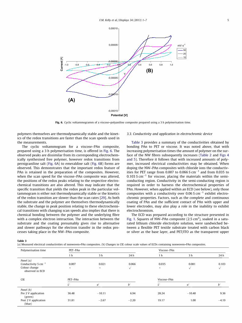
Fig. 6. Cyclic voltammogramm of a viscose–polyaniline composite prepared using a 3 h polymerisation time.
F.M. Kelly et al. / Displays 34 (2013) 1–7 5
polymers themselves are thermodynamically stable and the kinet-ics of the redox transitions are faster than the scan speeds used inthe measurements.
The cyclic voltammogram for a viscose–PAn composite,prepared using a 3 h polymerisation time, is offered in Fig. 6. Theobserved peaks are dissimilar from its corresponding electrochem-ically synthesised free polymer, however redox transitions frompernigraniline salt (Fig. 6A) to emeraldine salt (Fig. 6B) forms areobserved. This demonstrates that the important redox feature ofPAn is retained in the preparation of the composites. However,when the scan speed for the viscose–PAn composite was altered,the positions of the redox peaks relating to the respective electro-chemical transitions are also altered. This may indicate that thespecific transition that yields the redox peak in the particular vol-tammogram is either not thermodynamically stable or the kineticsof the redox transition are slower than the scan rates [29]. As boththe substrate and the polymer are themselves thermodynamicallystable, the change in peak position relating to these electrochemi-cal transitions with changing scan speeds also implies that there ischemical bonding between the polymer and the underlying fibrewith a complex electron interaction. The interaction between thesubstrate and the coating presumably gives rise to alternativeand slower pathways for the electron transfer in the redox pro-cesses taking place in the NW–PAn composite.
Table 3(a) Measured electrical conductivities of nonwoven–PAn composites. (b) Changes in CIE c
Polymerisation time PET–PAn
1 h 3 h
Panel (a)Conductivity S cm�1 0.007 0.021Colour change
observed in ECD� �
CIE PET–PAn
L� a�
Panel (b)Pre 2 V application
(green)36.48 �10.11
Post 2 V application(blue)
31.81 �2.67
3.3. Conductivity and application in electrochromic device
Table 3 provides a summary of the conductivities obtained bybonding PAn to PET or viscose. It was noted above, that withincreasing polymerisation times the amount of polymer on the sur-face of the NW fibres subsequently increases (Table 2 and Figs 4and 5). Therefore it follows that with increased amounts of poly-mer, increased electrical conductivities may be obtained. Whendoping the NW–PAn composites with chloride ions the conductiv-ities for PET range from 0.007 to 0.066 S cm�1 and from 0.035 to0.103 S cm�1 for viscose, placing the materials within the semi-conducting region. Conductivity in the semi-conducting region isrequired in order to harness the electrochemical properties ofPAn. However, when applied within an ECD (see below), only thosecomposites with a conductivity over 0.06 S cm�1 exhibit electro-chromic properties. Factors, such as the complete and continuouscoating of PAn and the sufficient contact of PAn with upper andlower electrodes, may also play a role in the inability to exhibitelectrochromism.
The ECD was prepared according to the structure presented inFig. 1. Squares of NW–PAn composite (2.5 cm2), soaked in a satu-rated lithium chloride electrolyte solution, were sandwiched be-tween a flexible PET textile substrate treated with carbon blackor silver as the base layer, and PET/ITO as the transparent upper
olour scale values of ECDs containing nonwoven–PAn composites.
Viscose–PAn
24 h 1 h 3 h 24 h
0.066 0.035 0.081 0.103p � p p
Viscose–PAn
b� L� a� b�
6.94 28.24 �10.40 9.36
�2.20 19.17 1.00 �4.19

Fig. 7. Flexible ECD containing viscose–PAn composite (a); before (b); and after (c) the application of �3 V for 1 min.
Fig. 8. UV–vis spectra of an ECD containing a viscose–PAn composite, showingstates 1 and 2, after 1 and 10 cycles.
6 F.M. Kelly et al. / Displays 34 (2013) 1–7
layer. Fig. 7a shows an ECD using a viscose–PAn composite thatwas prepared with a polymerisation time of 3 h. The flexible natureof the device is illustrated. The initial ECD prototype (identical de-vice structure) utilised an aqueous solution of Prussian Blue in theplace of PAn [26]. Due to the presence of an aqueous medium, suf-ficient sealing to retain the electrochromic solution within the flex-ible device was a significant challenge. However, because PAn isphysically bound to the nonwoven spacer textile of the ECD device,such problems are removed and the device may be held at any an-gle without the loss of electrochromic material.
When prepared, PAn is in its green emeraldine salt form. There-fore, to achieve pernigraniline salt, the oxidised state, �3 V was ap-plied to the device so as to initiate the redox reaction within thedevice (Eq. (1)).
ð1Þ
A colour change was observed from green to blue (Fig. 7b and c),after a time period of 1 min indicating that the change in redoxstate from emeraldine salt to perinigraniline salt was successful.Further electrical input is not required to retain the blue colour.The new redox state (and colour) remains due to the ‘‘memory’’ ef-fect of electrochromics [2]. CIE colour scale values for the colourchange from green to blue for both PET–PAn and viscose–PAn com-posites, prepared using a 3 h polymerisation time, are offered inTable 3. The switch to blue from green is confirmed by b� valuesbecoming negative. The 1 min time period required to switch the
PAn-containing ECD device from one oxidation state to another isanalogous to that of the Prussian Blue system [26]. However,4.5 V was required to initiate Prussian Blue redox reactions, com-pared to 3 V for PAn. Hence the lower working potential requiredby the PAn system is deemed an improvement.
When a potential of +3 V is applied to the device, with PAn in itsblue pernigraline state, the colour returned from blue to green. Thechange of colour from green (State 1) to blue (State 2) and then itsreturn to green, with the application of ±3 V, is considered a cycle.Fig. 8 illustrates the UV–vis spectra for cycles 1 and 10 of an ECDcontaining a viscose–PAn composite. The first cycle shows a shiftin the absorption band from ca. >700 nm (Cycle 1 – State 1) toca. >540 nm (Cycle 1 – State 2), due to a distinct change in the re-flected colour from green to blue. However, with the tenth cycle,no longer do the transitions between absorption peaks remain dis-tinct. Instead, a broad peak absorbing in the region 500–700 nm isobserved for both State 1 and State 2. The literature claims 100+cycles for PAn in rigid ECD systems, whereby PAn has been depos-ited electrochemically [30]. The poor cycling of our system may beattributed to the chemical bonding between PAn and PET or vis-cose. As was indicated by cyclic voltammetry above, the bond be-tween the NW and PAn gives rise to alternative and slowerpathways for electron transfer in redox processes. Thus the poly-mer is likely to become degraded with each redox reaction, limit-ing the reversibility of the system with each subsequent cycle.The ECD prototype device containing Prussian Blue also exhibiteda poor cycle lifetime, switching less than 10 times before oxidationof the electrochromic was observed. Therefore, in order to improvethe PAn system further, future work looks towards increasing thethickness of the polymer on the surface in order to reduce theinteraction with the underlying fibres. In doing this polymer degra-dation could be decreased and therefore, the ECD cycle lifeincreased.
4. Conclusions
Composites of the conducting polymer PAn with the flexibleNWs, PET or viscose, have been successfully prepared and charac-terised. The composites have been prepared by firstly bonding themonomer to the surface of the NW fibres, followed by subsequentpolymerisation with FeCl3. PAn coats each individual fibre of theNW spacer fabric. Increasing the polymerisation times increasesthe amount of polymer on the fibre surface. Composites with anelectrical conductivity of greater than 0.06 S cm�1 exhibited elec-trochromic properties when applied within a four-layer ECD. A col-our change was observed from green (emeraldine salt) to blue/purple (pernigraniline salt) when a potential of ±3 V is appliedfor 1 min. The colour change is reversible for up to 10 cycles. Thelow cycle number is likely due to the disruption of electron transferowing to the bonding of polymer to NW spacer textile. The use of asolid phase electrochromic has removed the need of sufficientsealing in order to retain a liquid phase electrochromic. However,because cycling is low, future work looks towards increasing the

F.M. Kelly et al. / Displays 34 (2013) 1–7 7
thickness of the polymer on the surface in order to reduce theinteraction with the underlying fibres and hence decrease polymerdegradation and increase the ECD cycle life.
Acknowledgements
We thank Institut d’Electronique, de Microélectronique et deNanotechnologie (IEMN), Université Lille 1, for the use of theirfacilities for the characterisation of composites.
References
[1] R.J. Mortimer, Organic electrochromic materials, Electrochim. Acta 44 (1999)2971–2981.
[2] P.R. Somani, S. Radhakrishnan, Electrochromic materials and devices: presentand future Mater, Chem. Phys. 77 (2003) 117–133.
[3] P. Tehrani, J. Isaksson, W. Mammo, M.R. Andersson, N.D. Robinson, M.Berggren, Evaluation of active materials designed for use in printableelectrochromic polymer displays, Thin Solid Films 515 (2006) 2485–2492.
[4] O.L. Shanmugasundaram, Smart and Intelligent Textiles, 2008. <http://www.indiantextilejournal.com/articles/FAdetails.asp?id=852>
[5] P.M.S. Monk, R.J. Mortimer, D.R. Rosseinsky, Electrochromism: Fundamentalsand Applications, VCH, Weinheim, 1995.
[6] Sage Electrochromics Inc. <http://www.sage-ec.com> (15 January, 2012).[7] Gentex Corporation. <http://www.gentex.com/automotive/product-categories>
(15 January, 2012).[8] R.J. Mortimer, A.L. Dyer, J.R. Reynolds, Electrochromic organic and polymeric
materials for display applications, Displays 27 (2006) 2–18.[9] D.R. Rosseinsky, R.J. Mortimer, Electrochromic systems and the prospects for
devices, Adv. Mater. 13 (2001) 783–793.[10] J. Silver, Chemical chameleons for electronics, In New Scientist (1989) 49–51.[11] O.D. Is, F.B. Koyuncu, S. Koyuncu, E. Ozdemir, A new imine coupled pyrrole–
carbazole–pyrrole polymer: electro-optical properties and electrochromism,Polymer 51 (2010) 1663–1669.
[12] K. Bange, T. Gambke, Electrochromic materials for optical switching devices,Adv. Mater. 2 (1990) 10–16.
[13] M.A.B. Gomes, D. Gonçalves, E.C. Pereira de Souza, B. Valla, M.A. Aegerter, L.O.S.Bulhões, Solid state electrochromic display based on polymer electrode-polymer electrolyte interface, Electrochim. Acta 37 (1992) 1653–1656.
[14] C.G. Granqvist, A. Azens, A. Hjelm, L. Kullman, G.A. Niklasson, D. Rönnow, M.Strømme Mattsson, M. Veszelei, G. Vaivars, Recent advances in
electrochromics for smart windows applications, Sol. Energy 63 (1998) 199–216.
[15] F. Carpi, D. De Rossi, Colours from electroactive polymers: electrochromic,electroluminescent and laser devices based on organic materials, Opt. LaserTechnol. 38 (2006) 292–305.
[16] P. Andersson, R. Forchheimer, P. Tehrani, M. Berggren, Printable all-organicelectrochromic active-matrix displays, Adv. Funct. Mater. 17 (2007) 3074–3082.
[17] A. Azens, E. Avendaño, J. Backholm, L. Berggren, G. Gustavsson, R. Karmhag,G.A. Niklasson, A. Roos, C.G. Granqvist, Flexible foils with electrochromiccoatings: science technology and applications, Mater. Sci. Eng. B – Solid 119(2005) 214–223.
[18] J.P. Coleman, A.T. Lynch, P. Madhukar, J.H. Wagenknecht, Printed, flexibleelectrochromic displays using interdigitated electrodes, Sol. Energy Mat. Sol. C56 (1999) 395–418.
[19] J. Liu, J.P. Coleman, Nanostructured metal oxides for printed electrochromicdisplays, Mater. Sci. Eng. A – Stuct. 286 (2000) 144–148.
[20] C. Ma, M. Taya, C. Xu, Flexible electrochromic device based on poly (3,4-(2,2-dimethylpropylenedioxy)thiophene), Electrochim. Acta 54 (2008) 598–605.
[21] D. Mecerreyes, R. Marcilla, E. Ochoteco, H. Grande, J.A. Pomposo, R. Vergaz, J.M.Sánchez Pena, A simplified all-polymer flexible electrochromic device,Electrochim. Acta 49 (2004) 3555–3559.
[22] H. Pagès, P. Topart, D. Lemordant, Wide band electrochromic displays based onthin conducting polymer films, Electrochim. Acta 46 (2001) 2137–2143.
[23] C.M. White, D.T. Gillaspie, E. Whitney, S.-H. Lee, A.C. Dillon, Flexibleelectrochromic devices based on crystalline WO3 nanostructures producedwith hot-wire chemical vapor deposition, Thin Solid Films 517 (2009) 3596–3599.
[24] W. Knight, Most flexible electronic paper yet revealed. <http://www.newscientist.com/article/dn4602> (26 January 2004).
[25] D. Tobjörk, R. Österbacka, Paper electronics, Adv. Mater. 23 (2011) 1935–1961.
[26] L. Meunier, F.M. Kelly, C. Cochrane, V. Koncar, Flexible displays for smartclothing: Part II – Electrochromic displays, Indian J. Fibre. Text. 36 (2011) 429–435.
[27] F.M. Kelly, J.H. Johnston, T. Borrmann, M.J. Richardson, Functionalised hybridmaterials of conducting polymers with individual cellulose fibres, Eur. J. Inorg.Chem. 35 (2007) 5571–5577.
[28] G.C. Wallace, Conductive Electroactive Polymers: Intelligent MaterialsSystems, CRC Press, Boca Raton, Florida, 2003.
[29] A.J. Bard, L.R. Faulkner, Electrochemical Methods: Fundamentals andApplications, Wiley, 1980.
[30] R. Prakash, Electrochemistry of polyaniline: study of the pH effect andelectrochromism, J. Appl. Polym. Sci. 83 (2002) 378–385.