Embed Size (px)
DESCRIPTION
Polled Serial Communications. These lecture notes created by Dr. Alex Dean, NCSU. In these notes. Why serial? Serial Communications RS232 standard UART operation Polled Code Interrupt Driven Code Read M16C/62 Hardware Manual (Serial I/O). Why Communicate Serially?. - PowerPoint PPT Presentation
Citation preview
1
Polled Serial CommunicationsPolled Serial Communications
These lecture notes created by Dr. Alex Dean, NCSU
2
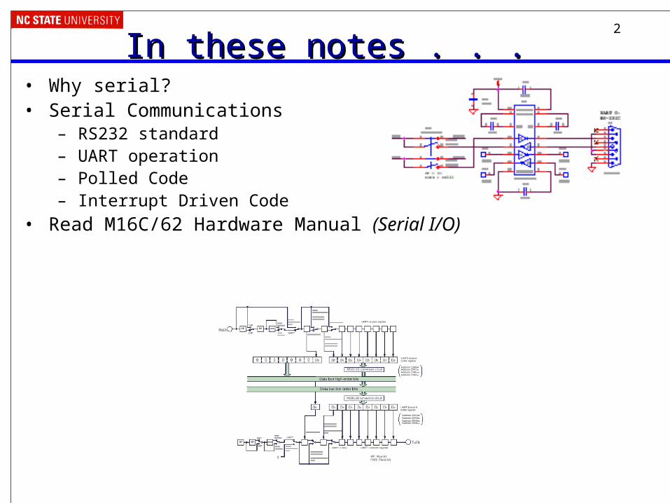
In these notes . . . In these notes . . . • Why serial?• Serial Communications
– RS232 standard– UART operation– Polled Code– Interrupt Driven Code
• Read M16C/62 Hardware Manual (Serial I/O)
3
Why Communicate Serially?Why Communicate Serially?• Native word size is multi-bit (8, 16, 32, etc.)• Often it’s not feasible to support sending all the word’s
bits at the same time– Cost and weight: more wires needed, larger connectors needed
– Mechanical reliability: more wires => more connector contacts to fail
– Timing Complexity: some bits may arrive later than others due to variations in capacitance and resistance across conductors
– Circuit complexity and power: may not want to have 16 different radio transmitters + receivers in the system
4
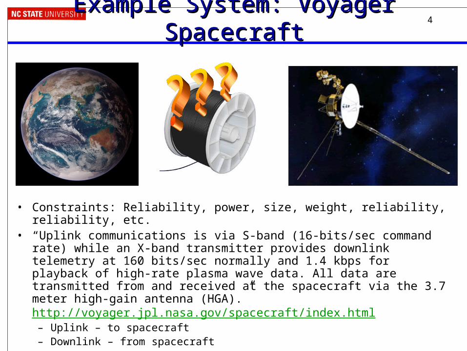
Example System: Voyager SpacecraftExample System: Voyager Spacecraft
• Constraints: Reliability, power, size, weight, reliability, reliability, etc. • “Uplink communications is via S-band (16-bits/sec command rate) while an X-
band transmitter provides downlink telemetry at 160 bits/sec normally and 1.4 kbps for playback of high-rate plasma wave data. All data are transmitted from and received at the spacecraft via the 3.7 meter high-gain antenna (HGA).” http://voyager.jpl.nasa.gov/spacecraft/index.html – Uplink – to spacecraft– Downlink – from spacecraft
5
How can we communicate serially?How can we communicate serially?• Need clocking information
– When does a word start?– When is a bit being sent?– When does a word end?
• Options– Explicit clock – synchronous
• Separate signal– SPI has 1 clock and 1 data line
• Modify signal to provide clocking– Example: short pulse = 0, long pulse = 1
– Implicit clock – asynchronous• Transmitter and receiver follow same rules (protocol)• Protocol specifies how to know when word starts, when to sample bits,
when word is done– Maybe also error detection and other information
6
Asynchronous Serial Communication BasicsAsynchronous Serial Communication Basics
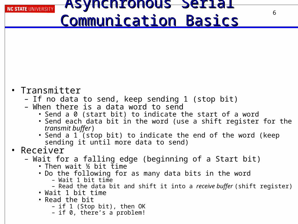
• Transmitter– If no data to send, keep sending 1 (stop bit)– When there is a data word to send
• Send a 0 (start bit) to indicate the start of a word• Send each data bit in the word (use a shift register for the transmit buffer)• Send a 1 (stop bit) to indicate the end of the word (keep sending it until more data
to send)• Receiver
– Wait for a falling edge (beginning of a Start bit)• Then wait ½ bit time • Do the following for as many data bits in the word
– Wait 1 bit time– Read the data bit and shift it into a receive buffer (shift register)
• Wait 1 bit time• Read the bit
– if 1 (Stop bit), then OK– if 0, there’s a problem!
7
For this to work…For this to work…• Transmitter and receiver must agree on several things
(protocol)– Order of data bits
– Number of data bits
– What a start bit is (1 or 0)
– What a stop bit is (1 or 0)
– How long a bit lasts• Transmitter and receiver clocks must be pretty close, since the only
timing reference is the start of the start bit
8
Serial Communication SpecificsSerial Communication Specifics
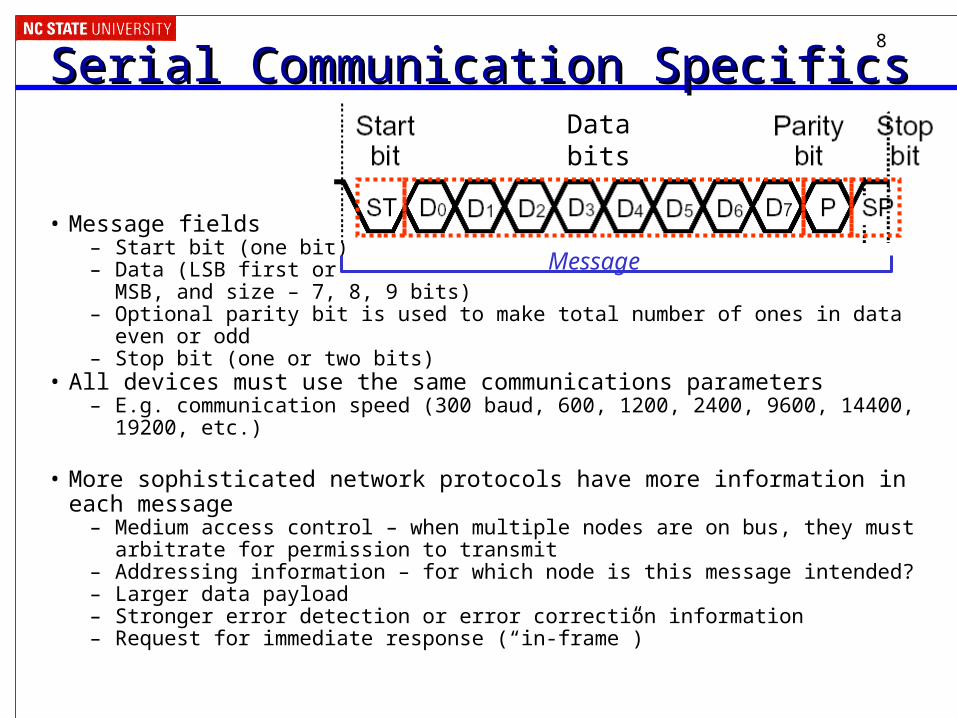
• Message fields– Start bit (one bit)– Data (LSB first or
MSB, and size – 7, 8, 9 bits)– Optional parity bit is used to make total number of ones in data even or odd– Stop bit (one or two bits)
• All devices must use the same communications parameters – E.g. communication speed (300 baud, 600, 1200, 2400, 9600, 14400, 19200, etc.)
• More sophisticated network protocols have more information in each message– Medium access control – when multiple nodes are on bus, they must arbitrate for
permission to transmit– Addressing information – for which node is this message intended?– Larger data payload– Stronger error detection or error correction information– Request for immediate response (“in-frame”)
Message
Databits
9
UART ConceptsUART Concepts• UART
– Universal – configurable to fit protocol requirements (for the whole universe)
– Asynchronous – no clock line needed to deserialize bits
– Receiver/Transmitter
• M30626 has three– UART0, 1, and 2
– UART1 talks to FoUSB-Mon circuit on back of board, enables us to do in-circuit debugging
– Can operate in asynchronous or synchronous (not used here) modes
– See MCU Hardware Manual for details, or else the remaining slides might be confusing
10
UART ConceptsUART Concepts
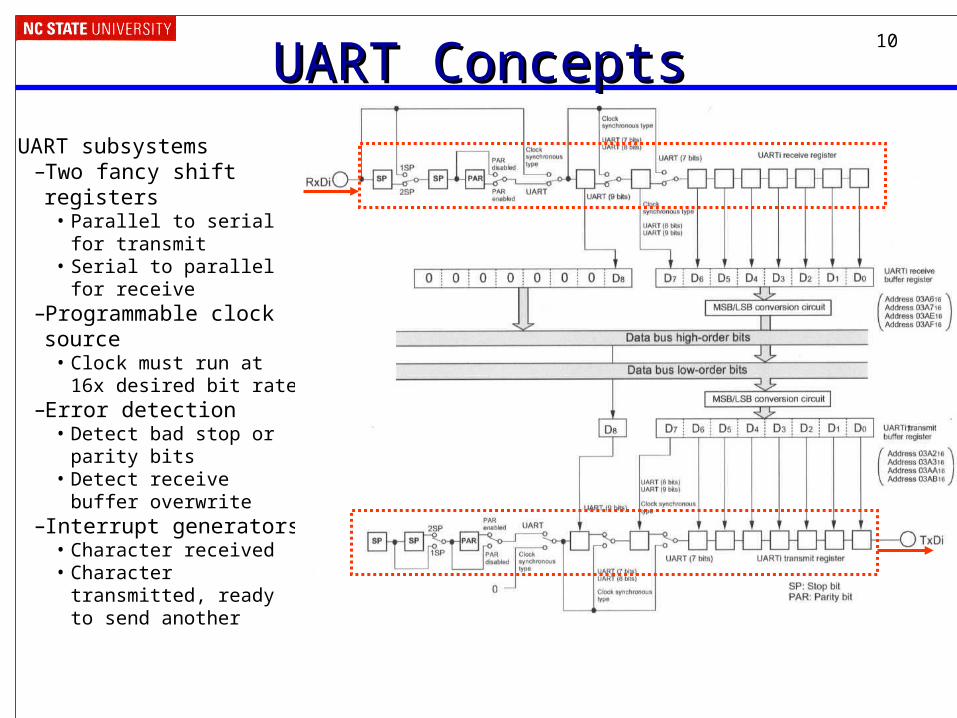
UART subsystems–Two fancy shift registers
• Parallel to serial for transmit
• Serial to parallel for receive
–Programmable clock source
• Clock must run at 16x desired bit rate
–Error detection• Detect bad stop or parity
bits• Detect receive buffer
overwrite–Interrupt generators
• Character received• Character transmitted,
ready to send another
11
Setting up the Serial PortSetting up the Serial Port• We will use UART 0, so all of the references to a
UART will have “u0” in them.• There are several control registers to set up before
communicating– Set the port speed
– Select 8 data bits, no parity, one stop bit (8N1)
– Enable transmitter and receiver
• Code examples:– SerPoll, SerInt
– Renesas application note and code for UART (check baud rate!)
12
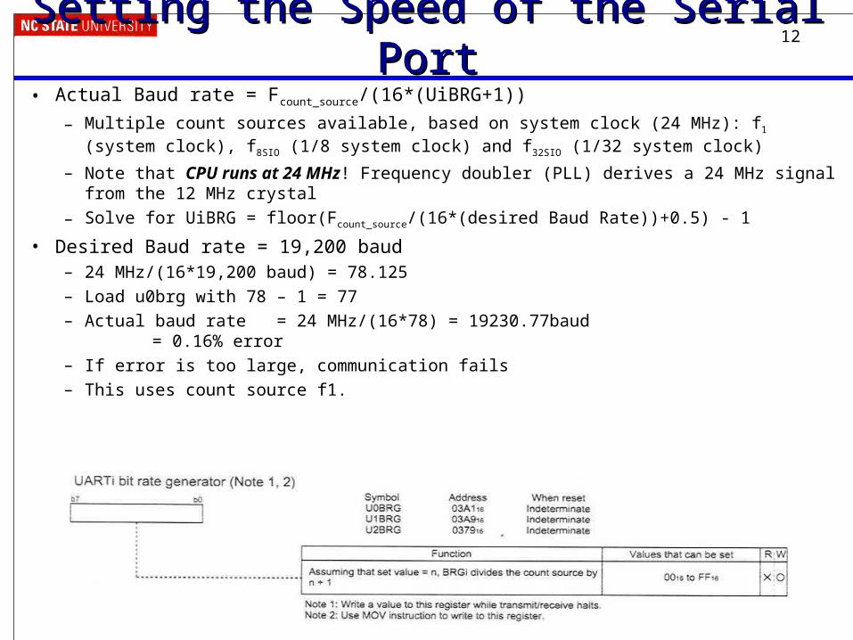
Setting the Speed of the Serial PortSetting the Speed of the Serial Port• Actual Baud rate = Fcount_source/(16*(UiBRG+1))
– Multiple count sources available, based on system clock (24 MHz): f1 (system clock), f8SIO (1/8 system clock) and f32SIO (1/32 system clock)
– Note that CPU runs at 24 MHz! Frequency doubler (PLL) derives a 24 MHz signal from the 12 MHz crystal
– Solve for UiBRG = floor(Fcount_source/(16*(desired Baud Rate))+0.5) - 1
• Desired Baud rate = 19,200 baud– 24 MHz/(16*19,200 baud) = 78.125
– Load u0brg with 78 – 1 = 77
– Actual baud rate = 24 MHz/(16*78) = 19230.77baud = 0.16% error
– If error is too large, communication fails
– This uses count source f1.
13
More Baud Rate ExamplesMore Baud Rate Examples• 24 MHz clock, 57600 baud
• 10 MHz clock, 1234 baud
14
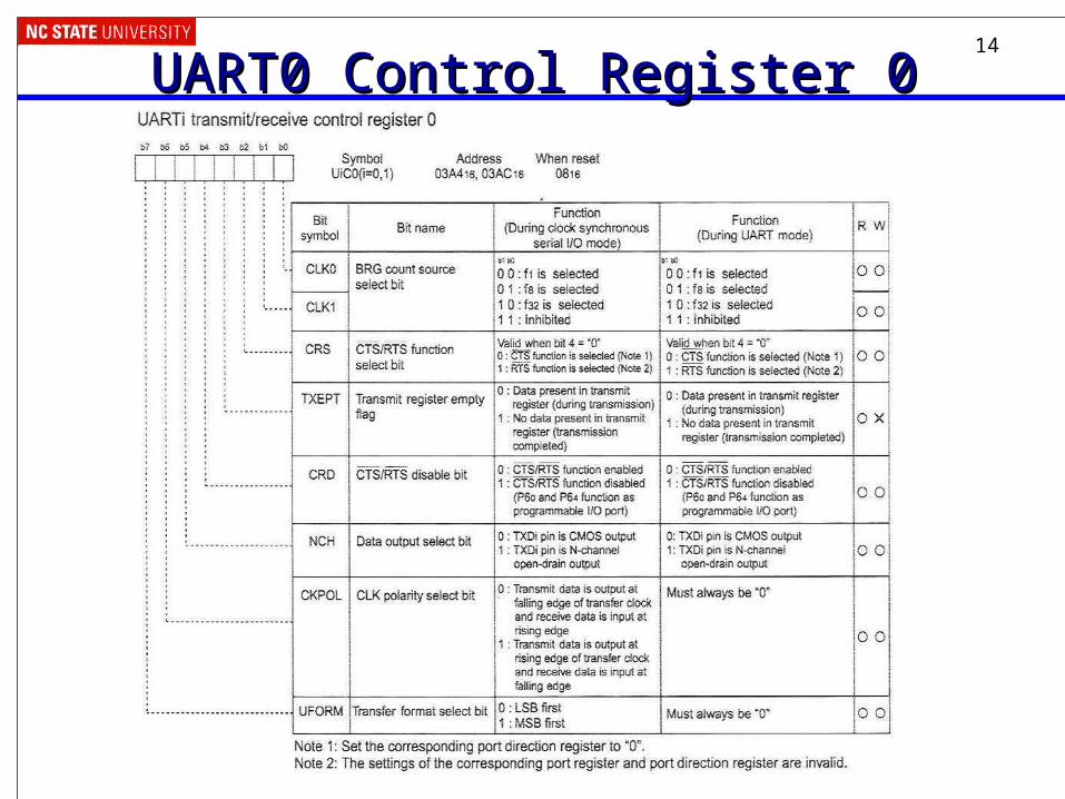
UART0 Control Register 0UART0 Control Register 0
15
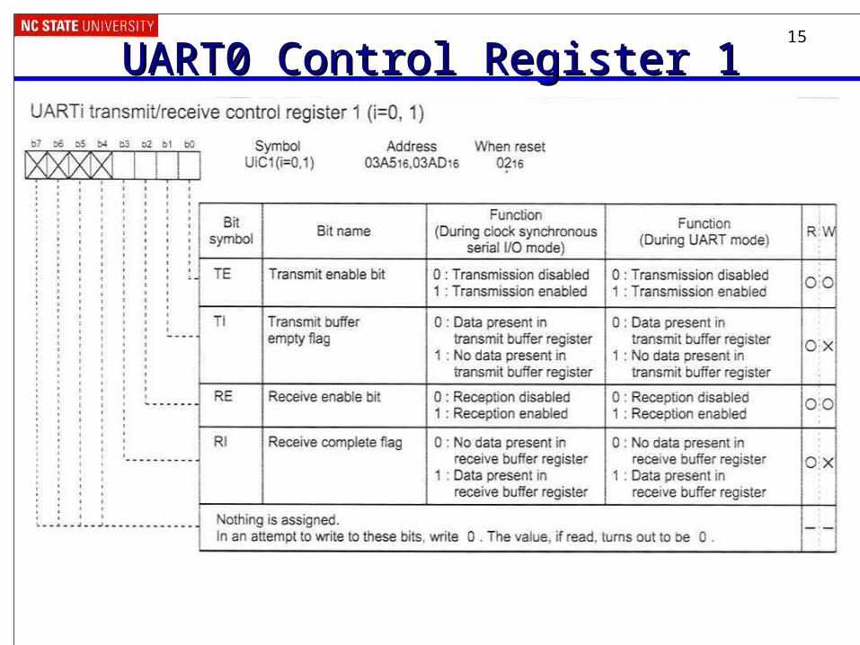
UART0 Control Register 1UART0 Control Register 1
16
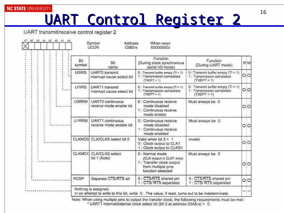
UART Control Register 2UART Control Register 2
17
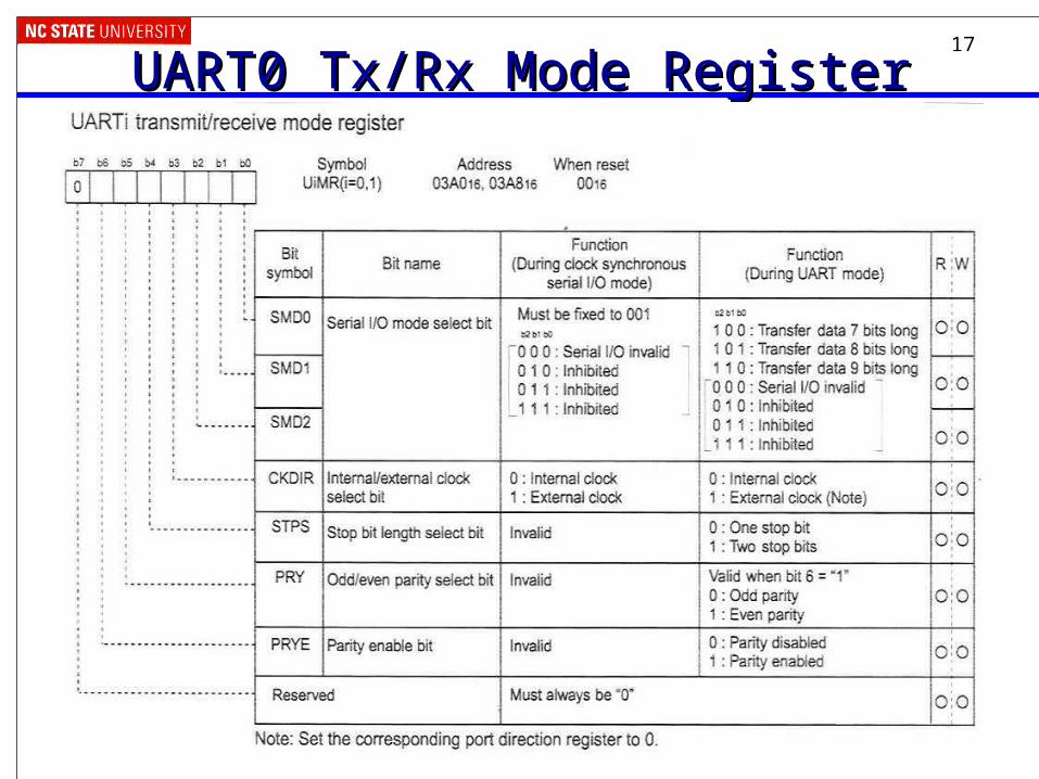
UART0 Tx/Rx Mode RegisterUART0 Tx/Rx Mode Register
18
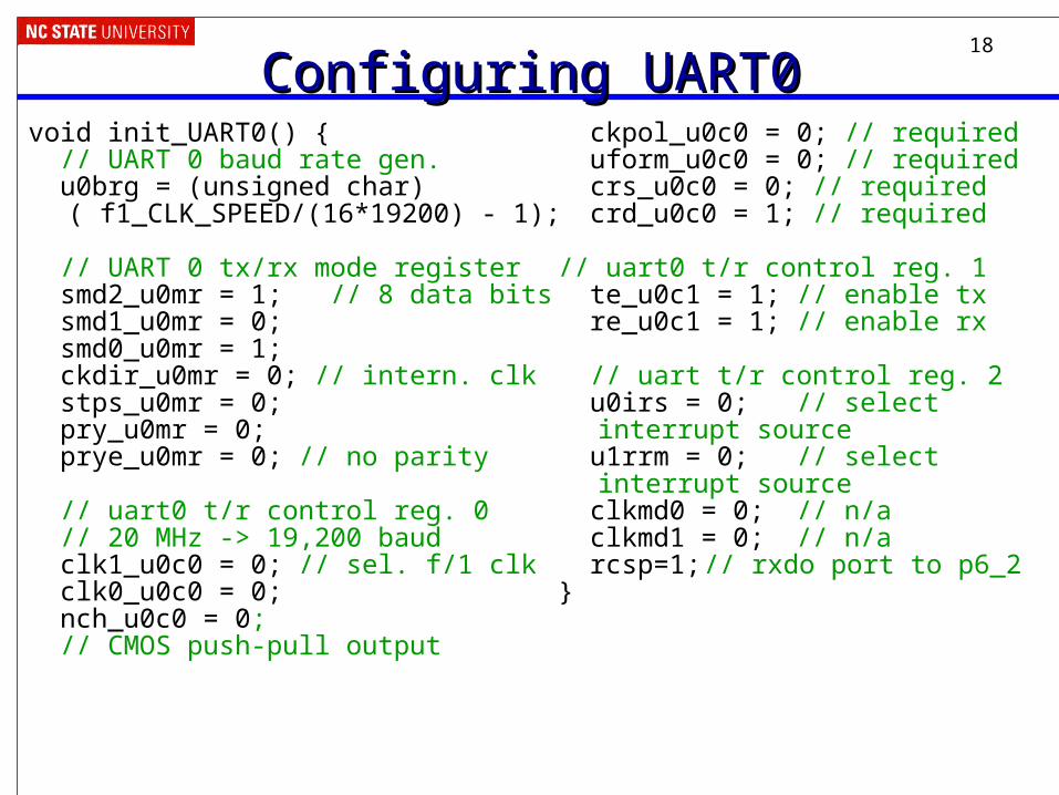
Configuring UART0Configuring UART0void init_UART0() { // UART 0 baud rate gen. u0brg = (unsigned char)
( f1_CLK_SPEED/(16*19200) - 1);
// UART 0 tx/rx mode register smd2_u0mr = 1; // 8 data bits smd1_u0mr = 0; smd0_u0mr = 1; ckdir_u0mr = 0; // intern. clk stps_u0mr = 0; pry_u0mr = 0; prye_u0mr = 0; // no parity
// uart0 t/r control reg. 0 // 20 MHz -> 19,200 baud clk1_u0c0 = 0; // sel. f/1 clk clk0_u0c0 = 0; nch_u0c0 = 0; // CMOS push-pull output
ckpol_u0c0 = 0; // required uform_u0c0 = 0; // required crs_u0c0 = 0; // required crd_u0c0 = 1; // required
// uart0 t/r control reg. 1 te_u0c1 = 1; // enable tx re_u0c1 = 1; // enable rx
// uart t/r control reg. 2 u0irs = 0; // select
interrupt source u1rrm = 0; // select
interrupt source clkmd0 = 0; // n/a clkmd1 = 0; // n/a rcsp=1;// rxdo port to p6_2 }
19
Using the UARTUsing the UART• When can we transmit?
– Transmit buffer must be empty
– Can poll ti_u0c1 (UART0, control register 1, transmit buffer empty, 0x03A5, bit 1)
– Or we can use an interrupt, in which case we will need to queue up data
• Put data to be sent into u0tbl (UART0, transmitter buffer, low byte, 0x03A2)
• Notice the differences between ones (1) and ells (l)
• When can we receive a byte?– Receive buffer must be full
– Can poll ri_u0c1 (UART0, control register 1, receive complete flag, 0x03A5, bit 3)
– Or we can use an interrupt, and again we will need to queue the data
• Get data from u0rbl (UART0, receive buffer, low byte, 0x03A6)
20
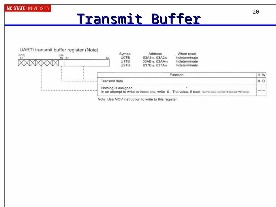
Transmit BufferTransmit Buffer
21
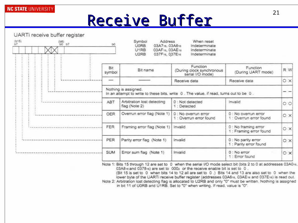
Receive BufferReceive Buffer
22
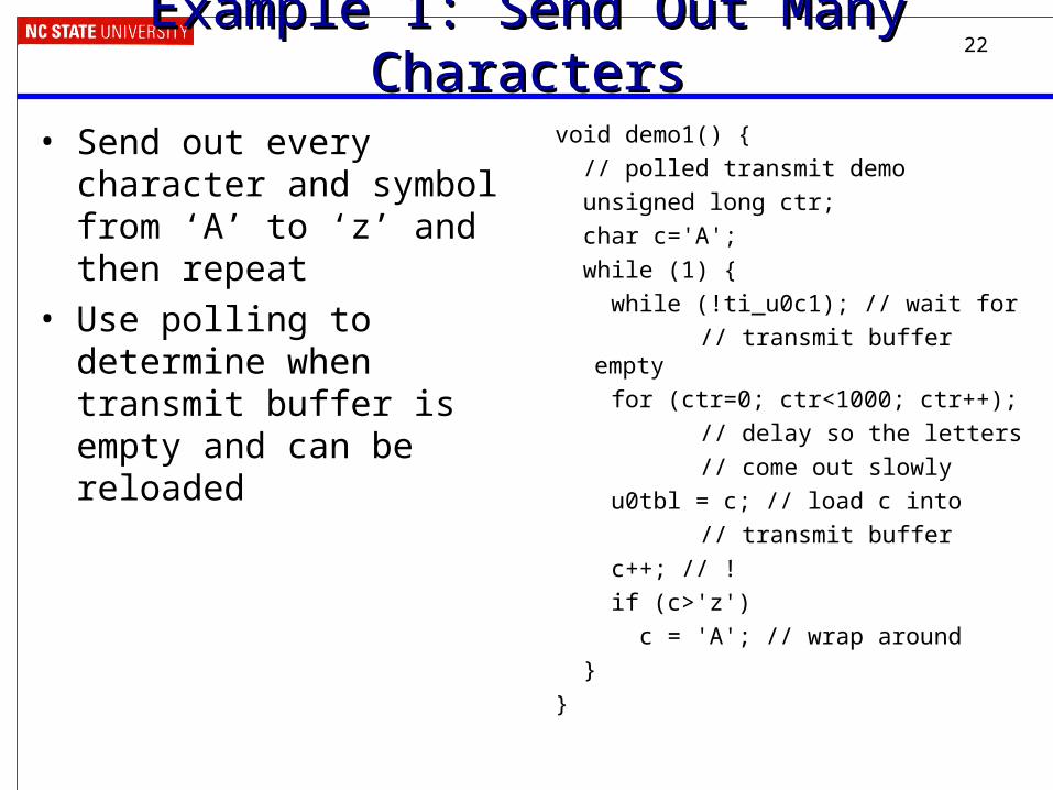
Example 1: Send Out Many CharactersExample 1: Send Out Many Characters• Send out every character and
symbol from ‘A’ to ‘z’ and then repeat
• Use polling to determine when transmit buffer is empty and can be reloaded
void demo1() { // polled transmit demo unsigned long ctr; char c='A'; while (1) { while (!ti_u0c1); // wait for
// transmit buffer empty
for (ctr=0; ctr<1000; ctr++);// delay so the letters// come out slowly
u0tbl = c; // load c into // transmit buffer
c++; // ! if (c>'z') c = 'A'; // wrap around }}
23
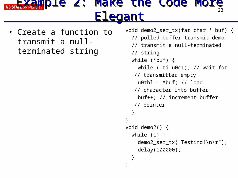
Example 2: Make the Code More ElegantExample 2: Make the Code More Elegant• Create a function to transmit a
null-terminated string
void demo2_ser_tx(far char * buf) {
// polled buffer transmit demo // transmit a null-terminated // string while (*buf) { while (!ti_u0c1); // wait for
// transmitter empty u0tbl = *buf; // load
// character into buffer
buf++; // increment buffer // pointer
}} void demo2() { while (1) { demo2_ser_tx("Testing!\n\r"); delay(100000); }}
24
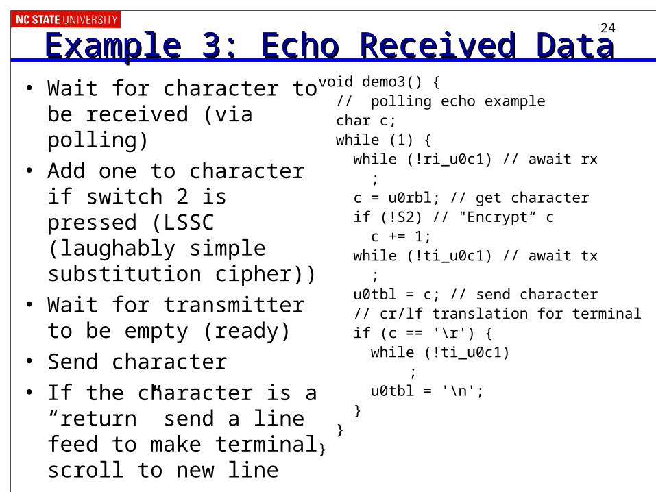
Example 3: Echo Received DataExample 3: Echo Received Data• Wait for character to be
received (via polling)
• Add one to character if switch 2 is pressed (LSSC (laughably simple substitution cipher))
• Wait for transmitter to be empty (ready)
• Send character
• If the character is a “return” send a line feed to make terminal scroll to new line
void demo3() { // polling echo example char c; while (1) { while (!ri_u0c1) // await rx ; c = u0rbl; // get character if (!S2) // "Encrypt“ c c += 1; while (!ti_u0c1) // await tx ; u0tbl = c; // send character // cr/lf translation for terminal if (c == '\r') { while (!ti_u0c1)
; u0tbl = '\n'; } }}
25
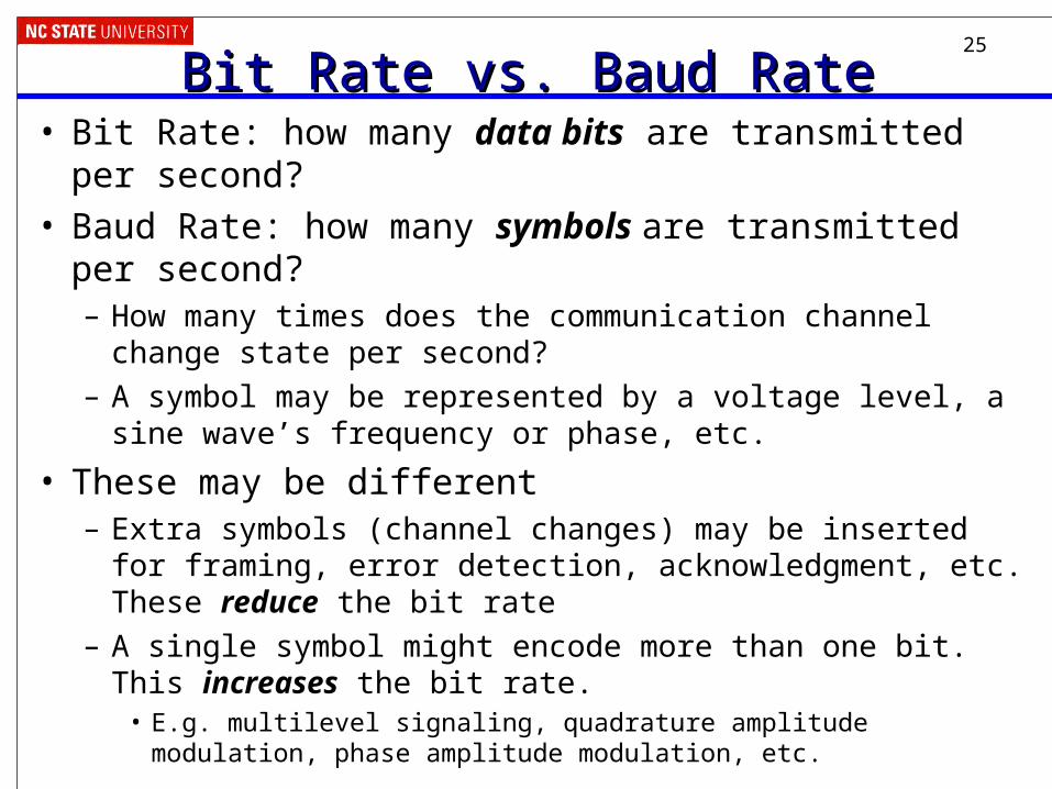
Bit Rate vs. Baud RateBit Rate vs. Baud Rate• Bit Rate: how many data bits are transmitted per second?• Baud Rate: how many symbols are transmitted per
second? – How many times does the communication channel change state
per second?
– A symbol may be represented by a voltage level, a sine wave’s frequency or phase, etc.
• These may be different– Extra symbols (channel changes) may be inserted for framing,
error detection, acknowledgment, etc. These reduce the bit rate
– A single symbol might encode more than one bit. This increases the bit rate.
• E.g. multilevel signaling, quadrature amplitude modulation, phase amplitude modulation, etc.
26
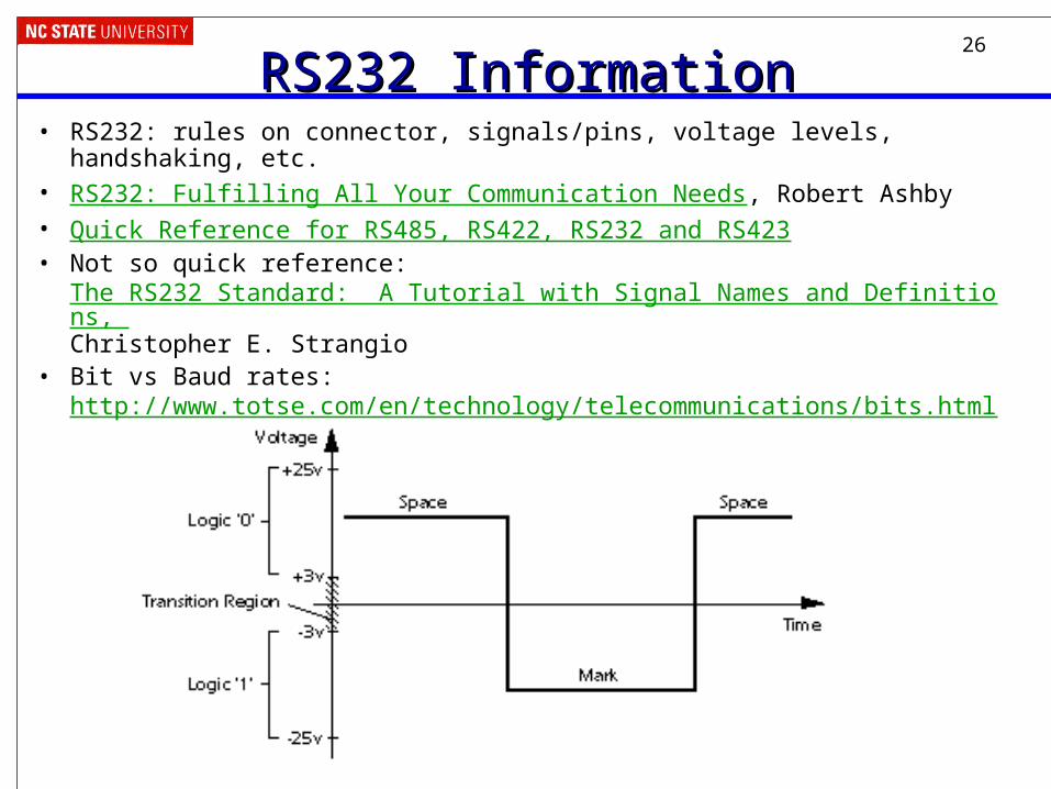
RS232 InformationRS232 Information• RS232: rules on connector, signals/pins, voltage levels, handshaking, etc.• RS232: Fulfilling All Your Communication Needs, Robert Ashby• Quick Reference for RS485, RS422, RS232 and RS423• Not so quick reference:
The RS232 Standard: A Tutorial with Signal Names and Definitions, Christopher E. Strangio
• Bit vs Baud rates: http://www.totse.com/en/technology/telecommunications/bits.html
27
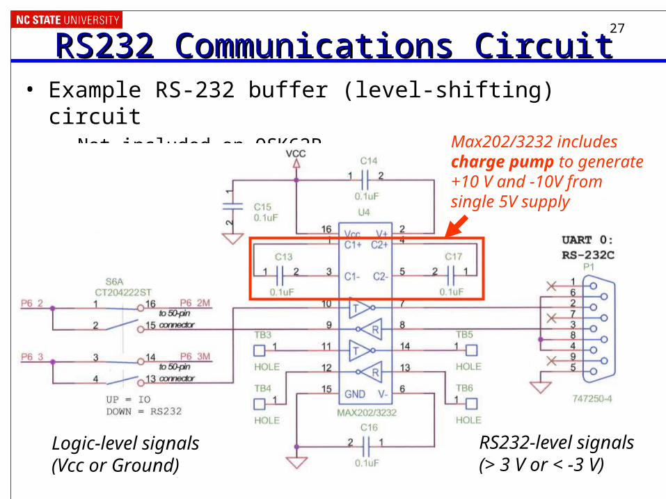
RS232 Communications CircuitRS232 Communications Circuit• Example RS-232 buffer (level-shifting) circuit
– Not included on QSK62PMax202/3232 includescharge pump to generate+10 V and -10V from single 5V supply
Logic-level signals(Vcc or Ground)
RS232-level signals(> 3 V or < -3 V)