Embed Size (px)
Citation preview
12 May 2019
POLITECNICO DI TORINORepository ISTITUZIONALE
A Real Time Distributed Approach to Collision Avoidance for Industrial Manipulators / Fenucci A.;Indri M.;Romanelli F.. -ELETTRONICO. - (2014). ((Intervento presentato al convegno 2014 IEEE International Conference on EmergingTechnologies and Factory Automation (ETFA 2014) tenutosi a Barcelona (Spain) nel 16-19 Settembre 2014.
Original
A Real Time Distributed Approach to Collision Avoidance for Industrial Manipulators
Publisher:
PublishedDOI:
Terms of use:openAccess
Publisher copyright
(Article begins on next page)
This article is made available under terms and conditions as specified in the corresponding bibliographic description inthe repository
Availability:This version is available at: 11583/2565550 since:
IEEE - INST ELECTRICAL ELECTRONICS ENGINEERS INC
A Real Time Distributed Approach to Collision Avoidancefor Industrial Manipulators
Alba Fenucci, Marina IndriDipartimento di Automatica e Informatica,
Politecnico di TorinoCorso Duca degli Abruzzi 24, 10129 Torino, Italy
[email protected]@polito.it
Fabrizio RomanelliResearch & Development group in Motion
and Control of Comau RoboticsVia Rivalta 30, 10095 Grugliasco, Italy
Abstract
Robot interaction with the surrounding environment isan important and newsworthy problem in the context ofindustrial and service robotics. Collision avoidance givesthe robot the ability to avoid contacts with objects aroundit, but most of the industrial controls implementing col-lision avoidance checks only the robot Tool Center Point(TCP) over the objects in the cell, without taking into ac-count the shape of the tool, mounted on the robot flange.In this paper a novel approach is proposed, based on anaccurate 3D simulation of the robotic cell. A distributedreal time computing approach has been chosen to avoidany overloading of the robot controller. The simulator andthe client application are implemented in a personal com-puter, connected via a TCP-IP socket to the robot con-troller, which hosts and manages the anti-collision poli-cies, based on a proper speed override control. The realtime effectiveness of the proposed approach has been con-firmed by experimental tests, carried out for a real indus-trial setup in two different scenarios.
1. Introduction
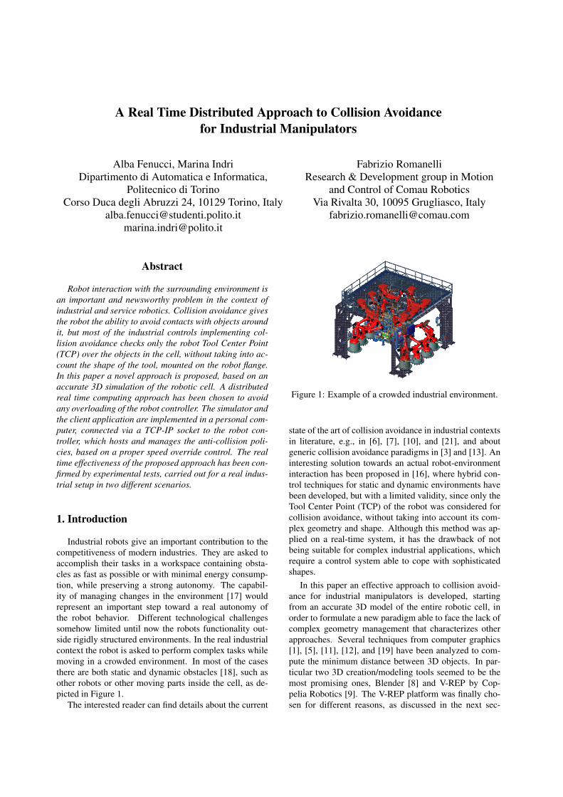
Industrial robots give an important contribution to thecompetitiveness of modern industries. They are asked toaccomplish their tasks in a workspace containing obsta-cles as fast as possible or with minimal energy consump-tion, while preserving a strong autonomy. The capabil-ity of managing changes in the environment [17] wouldrepresent an important step toward a real autonomy ofthe robot behavior. Different technological challengessomehow limited until now the robots functionality out-side rigidly structured environments. In the real industrialcontext the robot is asked to perform complex tasks whilemoving in a crowded environment. In most of the casesthere are both static and dynamic obstacles [18], such asother robots or other moving parts inside the cell, as de-picted in Figure 1.
The interested reader can find details about the current
Figure 1: Example of a crowded industrial environment.
state of the art of collision avoidance in industrial contextsin literature, e.g., in [6], [7], [10], and [21], and aboutgeneric collision avoidance paradigms in [3] and [13]. Aninteresting solution towards an actual robot-environmentinteraction has been proposed in [16], where hybrid con-trol techniques for static and dynamic environments havebeen developed, but with a limited validity, since only theTool Center Point (TCP) of the robot was considered forcollision avoidance, without taking into account its com-plex geometry and shape. Although this method was ap-plied on a real-time system, it has the drawback of notbeing suitable for complex industrial applications, whichrequire a control system able to cope with sophisticatedshapes.
In this paper an effective approach to collision avoid-ance for industrial manipulators is developed, startingfrom an accurate 3D model of the entire robotic cell, inorder to formulate a new paradigm able to face the lack ofcomplex geometry management that characterizes otherapproaches. Several techniques from computer graphics[1], [5], [11], [12], and [19] have been analyzed to com-pute the minimum distance between 3D objects. In par-ticular two 3D creation/modeling tools seemed to be themost promising ones, Blender [8] and V-REP by Cop-pelia Robotics [9]. The V-REP platform was finally cho-sen for different reasons, as discussed in the next sec-
tion, and especially because it includes a versatile Mesh-Mesh distance calculator module. A distributed real timecomputing approach (see e.g., [20], [22], and [23]) hasbeen chosen to avoid any overloading of the robot con-troller, implementing the simulator and the client appli-cation in a personal computer, connected via a TCP-IPsocket to the robot controller, which hosts and managesthe anti-collision policies. The proposed procedure, whichis mainly based on proper policies of speed override con-trol, can be applied to different manipulators and/or to var-ious configurations of the robotic cell, possibly includingmore robots simultaneously working inside it. In partic-ular, two scenarios have been considered for the experi-mental tests: a redundant 7-dof robot prototype movingin presence of a static obstacle that must be bypassed,and two Comau 6-dof industrial manipulators (a SMART5SIX and a SMART NS12) cooperatively working in a cell.
The paper is organized as follows. An overview of theproposed collision avoidance approach is given in Section2, while Section 3 is devoted to its software architecture,including the Virtual 3D model, the client application andthe robot control unit, hosting the speed override policiesfor collision avoidance. The effectiveness of the proposedapproach is experimentally tested in Section 4 in the twoconsidered scenarios. Section 5 draws some final conclu-sions and highlights the potentialities of the proposed plat-form for future developments.
2. Overview of the collision avoidance ap-proach
The goal of the proposed approach is to avoid any colli-sion between a robot and other (static or dynamic) objectsin the cell, by adequately modifying the robot speed over-ride on the basis of the minimum distance between anypart of the robot and any element in the cell. A key pointis given by the capability of correctly and efficiently de-termining such a minimum distance. A possible, simpli-fied solution would consist in modeling the robot, the tool,and the items in the cell by composing simple solids, likespheres, cylinders and boxes. But in this way all the mod-eled objects would be bigger than the real correspondingones, and moreover the results thus obtained would be in-accurate, because the solids could not perfectly model allthe objects in the scene. The first element of the proposedapproach is then given by an accurate virtual replica ofthe status of the cell, developed in the V-REP simulator,where distances between complex objects in the roboticcell can be correctly computed. V-REP [9], which is gen-erally used for factory automation simulations, allows anaccurate modeling of the robot and of the entire cell, in-cluding objects of different, complex shapes. It has beenchosen for various reasons: it is supported from severalprogramming languages (C/C++, Python, Java, Matlab),it does not require strong computational resources for acomplex simulation, it can simulate more robots simul-taneously, and it is an open source software with free li-cense for educational purposes, but most of all it includes
a Mesh-Mesh distance calculator module that allows fastminimum distance calculations between any shape (con-vex, concave, open, closed, etc.) in the scene.
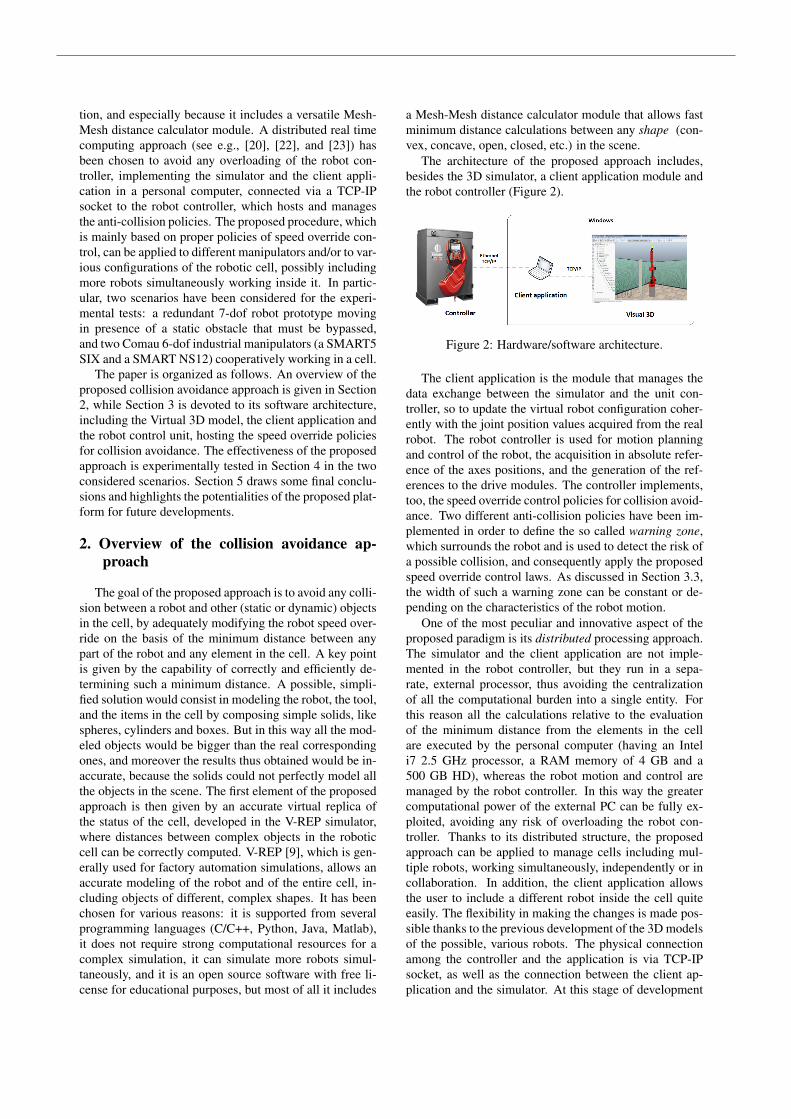
The architecture of the proposed approach includes,besides the 3D simulator, a client application module andthe robot controller (Figure 2).
Figure 2: Hardware/software architecture.
The client application is the module that manages thedata exchange between the simulator and the unit con-troller, so to update the virtual robot configuration coher-ently with the joint position values acquired from the realrobot. The robot controller is used for motion planningand control of the robot, the acquisition in absolute refer-ence of the axes positions, and the generation of the ref-erences to the drive modules. The controller implements,too, the speed override control policies for collision avoid-ance. Two different anti-collision policies have been im-plemented in order to define the so called warning zone,which surrounds the robot and is used to detect the risk ofa possible collision, and consequently apply the proposedspeed override control laws. As discussed in Section 3.3,the width of such a warning zone can be constant or de-pending on the characteristics of the robot motion.
One of the most peculiar and innovative aspect of theproposed paradigm is its distributed processing approach.The simulator and the client application are not imple-mented in the robot controller, but they run in a sepa-rate, external processor, thus avoiding the centralizationof all the computational burden into a single entity. Forthis reason all the calculations relative to the evaluationof the minimum distance from the elements in the cellare executed by the personal computer (having an Inteli7 2.5 GHz processor, a RAM memory of 4 GB and a500 GB HD), whereas the robot motion and control aremanaged by the robot controller. In this way the greatercomputational power of the external PC can be fully ex-ploited, avoiding any risk of overloading the robot con-troller. Thanks to its distributed structure, the proposedapproach can be applied to manage cells including mul-tiple robots, working simultaneously, independently or incollaboration. In addition, the client application allowsthe user to include a different robot inside the cell quiteeasily. The flexibility in making the changes is made pos-sible thanks to the previous development of the 3D modelsof the possible, various robots. The physical connectionamong the controller and the application is via TCP-IPsocket, as well as the connection between the client ap-plication and the simulator. At this stage of development
the software client application and the simulator run in aWindows-based not embedded operating system, obtain-ing good results, as illustrated in the next sections. Thedevelopment of the client application and of the simula-tor in a Linux-based system has been developed in a non-real-time context, and a full development for the real-timecontext is in progress.
3. Software architecture
In this section the main software components of the ar-chitecture sketched in Figure 2 are detailed: the virtual 3Dsimulator, the client application, the robot controller unitand the communication protocol. The avoidance collisionpolicies, implemented in the controller, are also described.
3.1. Virtual 3D simulatorThe main module of the architecture is the simulator,
which allows an accurate simulation of the real cell andevaluates at each time instant the minimum distance valuebetween the robot and any other item in the cell. The sim-ulator has a distributed structure, so that each model canbe controlled through an embedded script or an API calledby a remote client. The simulated scene is made-up ofdifferent scripts written in LUA: the base script task is de-voted to execute the client application, the other scriptsare related to the models of the items introduced into thescene. Each model has its own script that allows it to ex-change data with the client application. After the creationof the cell and the beginning of the simulation, the sim-ulator receives the joint position values of each robot asinputs (more than one robot could be present in the cell);while the simulation goes on, the joint values are continu-ously updated and the virtual robots consequently updatetheir configuration. Using its devoted Mesh-Mesh mod-ule, the simulator computes the minimum distance be-tween each robot in the cell and any element inside it, soto determine the overall distance minimum value (i.e., forwhich part of which robot in the cell a collision wouldbe going to happen). The Cartesian position of the robotpoint corresponding to the minimum distance situation isreturned by the simulator and transmitted to the client ap-plication. Thanks to this information, it is possible toknow which link of the robot is involved in the upcomingcollision, and hence properly modify its speed override, asdiscussed in Section 3.3.
3.2. Client applicationThe client application is written in C++ using the APIs
from V-REP; this is the core of the software architec-ture and it is responsible for the management of the in-formation exchanged between the Virtual 3D simulatorand the C5G controller. In order to accomplish this task,the C++ application is provided with two separate clients:the first one manages the connection with the C5G con-troller through TCP-IP sockets, the second one establishesa socket communication with V-REP, so to reduce delayand network load to a great extent. The client application
is also demanded to find which robot link corresponds tothe minimum distance measured and to acquire the veloc-ity signal of this link for all the robots in the cell. Theresults of all such computations are sent to the controller.
3.3. Robot control unit and speed override controlIn this approach, the controller has two main tasks: (i)
to supply to the simulator the positions of all the jointsof each robot in the cell, and (ii) to take decisions aboutpossible collisions.
The exchange of messages between the controller andthe application is accomplished through a protocol basedon bidirectional communication, where a client sends amessage and the server always answers to that message.The exchanged messages, which are treated as ASCIIstrings, are:
• the joint position request of all the controlled robots;
• for each robot the minimum distance measured froman external object, the corresponding link and its ve-locity.
The proposed anti-collision policies are based on robotspeed override control laws to be applied when the riskof a collision is detected, i.e., when the robot minimumdistance d from any obstacle is smaller than a safe thresh-old value dmax. Two different anti-collision policies havebeen formulated, both based on the definition of a properwarning zone surrounding the robot, characterized by twolimits: the upper bound dmax and the lower bound dmin.The basic idea of the policies is that if dmin < d < dmax,the velocity must be adequately reduced, because other-wise a collision is probably going to happen, whereas ifd < dmin the robot must be stopped as soon as possible.In the first proposed anti-collision policy the width of thewarning zone is constant, i.e., dmax and dmin are con-stant, and the speed override is uniformly changed insideit according to the following equation:
vok =
vok−1 ·
d− dmin
dmax − dminif dmin < d < dmax
vok−1 if d ≥ dmax
0 if d ≤ dmin
(1)where vok is the speed override of the robot at the k-th time instant. If the distance is smaller than the lowerbound of the warning zone, the robot immediately changesits state to the HOLD mode, in which its motion is stoppedas soon as possible. It must be underlined that only incase of approaching an obstacle a speed change is applied,by checking the link velocity considered in the measure-ment of the distance. If the robot is moving away fromthe obstacle, its speed is multiplied by a constant, to avoidany unnecessary slow down. dmax is chosen based onthe stopping distance of the robot, considering its highestspeed and acceleration; on the other hand, dmin representsa cushion distance in millimeters from the collision area.
A modified version of the speed override control hasbeen proposed considering the width of the warning zone
as a function of the characteristics of the motion of linki involved in the collision risk; in particular in this sec-ond policy the upper bound dmax varies according to thefollowing equation:
dmax =
{ vi2ai
+viai2ji
if dmax ≥ d̄
d̄ if dmax < d̄(2)
where vi is the velocity of the considered link, ai is itsacceleration, ji is its jerk, and d̄ is the minimum value al-lowed for dmax for safety reasons (in order to guaranteea proper stopping space in any case). The speed over-ride reduction has still a linear progression as in (1), butthe width of the warning zone varies, and in particular ahigher reduction of the robot velocity is imposed, whenthe link involved in the risk of a collision is moving veryquickly. In this way, as the link velocity increases, thewarning zone grows in order to take into account that awider stopping space is needed.
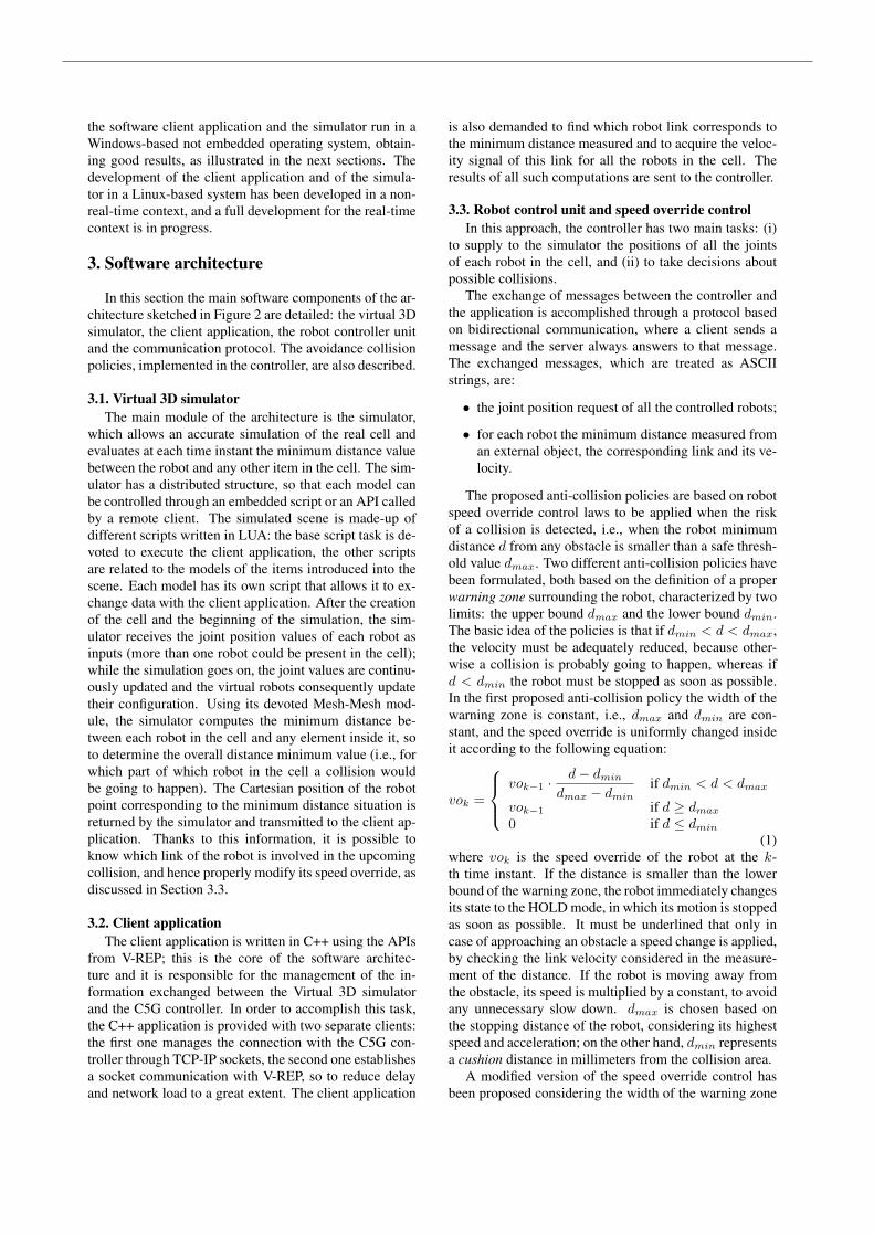
3.4. Communication protocolThree main phases can be distinguished into the com-
munication flow among the architecture components pre-viously described (as sketched in Figure 3): (i) initializa-tion, (ii) collision avoidance management, and (iii) termi-nation.
In the first phase, after the creation of the virtual celland the simulation start, the main script launches the clientapplication executable. The first task of the C++ applica-tion is then the connection to the two servers (i.e., Virtual3D and C5G Controller).
The second phase is relative to the key point of thewhole process, i.e., the collision avoidance procedure. Inthis phase the client application interrogates the controllerabout the joint position values of all the robots in the cell;after receiving these data, the application accordingly up-dates the virtual robots configuration. The Virtual 3D sim-ulator sends out to the client application the minimum dis-tance found between each robot and any element in the en-vironment, and the data relative to the corresponding link.The communication between the Virtual 3D simulator andthe client application is based on creation and deletion ofsignals, using a persistent global buffer. In order to ensurethe synchronicity between the application and the simu-lator, and the update of the data, the simulator looks forthe minimum distance and sends out a new message onlywhen all the other signals with the same name are not ac-tive. On the other hand, the application deletes the signalwhen it receives a new joint position from the controller.The signals are created according to the number of robotsinstantiated on the scene to be managed: this task is per-formed by each robot model script involved in the scene.The application finally sends to the robot controller theminimum distance value, the link number and its veloc-ity for the application of the collision avoidance policiesdescribed in Section 3.3.
The last phase of the communication flow occurs whenthe simulation ends: the client application closes all the
Figure 3: Communication flows.
communications to the servers and terminates its execu-tion.
4. Experimental tests
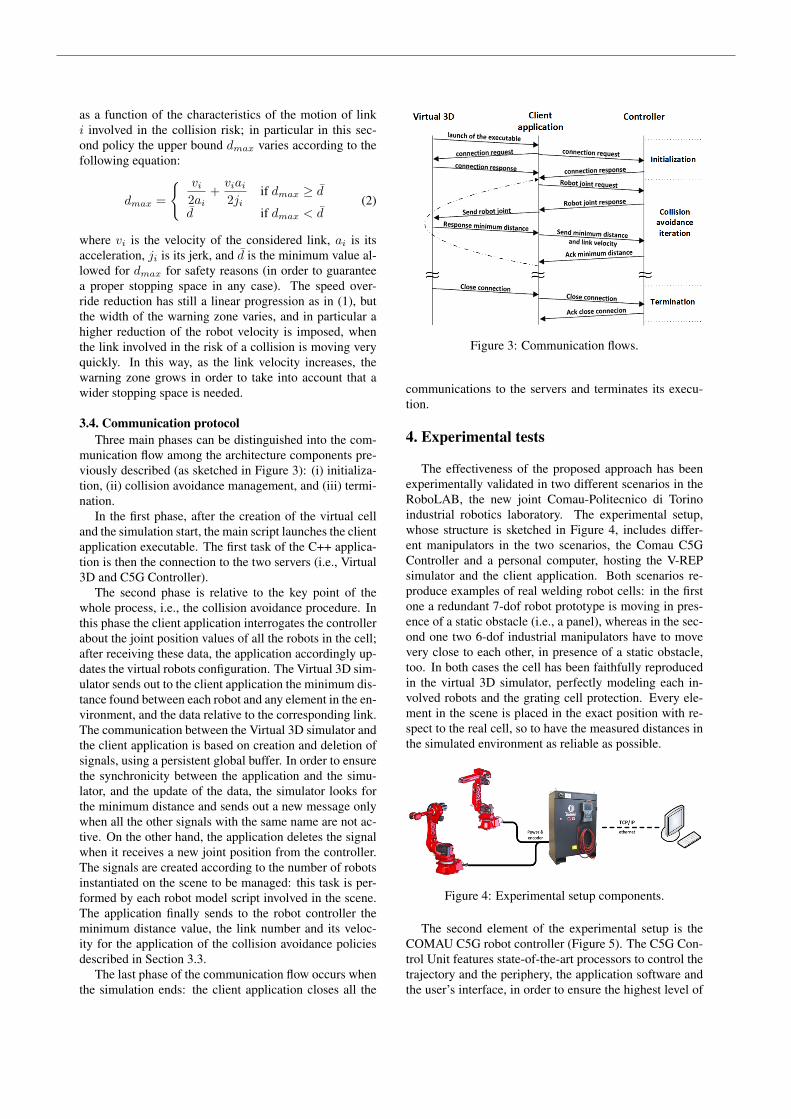
The effectiveness of the proposed approach has beenexperimentally validated in two different scenarios in theRoboLAB, the new joint Comau-Politecnico di Torinoindustrial robotics laboratory. The experimental setup,whose structure is sketched in Figure 4, includes differ-ent manipulators in the two scenarios, the Comau C5GController and a personal computer, hosting the V-REPsimulator and the client application. Both scenarios re-produce examples of real welding robot cells: in the firstone a redundant 7-dof robot prototype is moving in pres-ence of a static obstacle (i.e., a panel), whereas in the sec-ond one two 6-dof industrial manipulators have to movevery close to each other, in presence of a static obstacle,too. In both cases the cell has been faithfully reproducedin the virtual 3D simulator, perfectly modeling each in-volved robots and the grating cell protection. Every ele-ment in the scene is placed in the exact position with re-spect to the real cell, so to have the measured distances inthe simulated environment as reliable as possible.
Figure 4: Experimental setup components.
The second element of the experimental setup is theCOMAU C5G robot controller (Figure 5). The C5G Con-trol Unit features state-of-the-art processors to control thetrajectory and the periphery, the application software andthe user’s interface, in order to ensure the highest level of
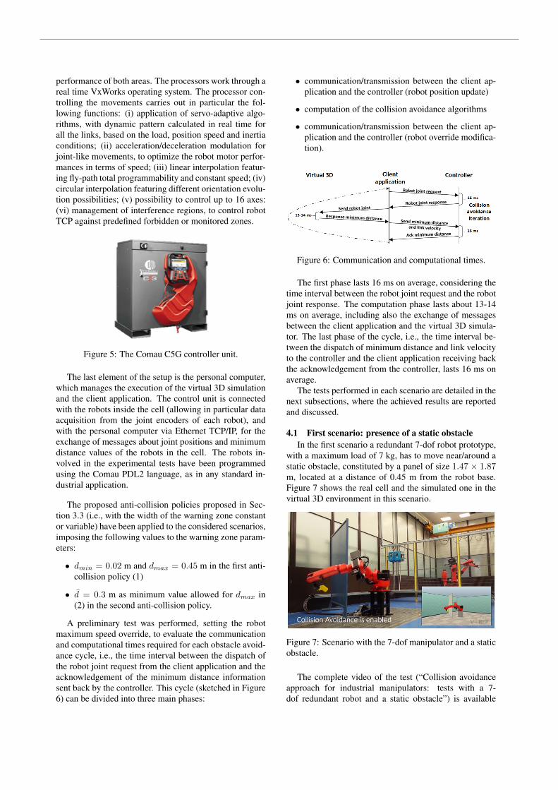
performance of both areas. The processors work through areal time VxWorks operating system. The processor con-trolling the movements carries out in particular the fol-lowing functions: (i) application of servo-adaptive algo-rithms, with dynamic pattern calculated in real time forall the links, based on the load, position speed and inertiaconditions; (ii) acceleration/deceleration modulation forjoint-like movements, to optimize the robot motor perfor-mances in terms of speed; (iii) linear interpolation featur-ing fly-path total programmability and constant speed; (iv)circular interpolation featuring different orientation evolu-tion possibilities; (v) possibility to control up to 16 axes:(vi) management of interference regions, to control robotTCP against predefined forbidden or monitored zones.
Figure 5: The Comau C5G controller unit.
The last element of the setup is the personal computer,which manages the execution of the virtual 3D simulationand the client application. The control unit is connectedwith the robots inside the cell (allowing in particular dataacquisition from the joint encoders of each robot), andwith the personal computer via Ethernet TCP/IP, for theexchange of messages about joint positions and minimumdistance values of the robots in the cell. The robots in-volved in the experimental tests have been programmedusing the Comau PDL2 language, as in any standard in-dustrial application.
The proposed anti-collision policies proposed in Sec-tion 3.3 (i.e., with the width of the warning zone constantor variable) have been applied to the considered scenarios,imposing the following values to the warning zone param-eters:
• dmin = 0.02 m and dmax = 0.45 m in the first anti-collision policy (1)
• d̄ = 0.3 m as minimum value allowed for dmax in(2) in the second anti-collision policy.
A preliminary test was performed, setting the robotmaximum speed override, to evaluate the communicationand computational times required for each obstacle avoid-ance cycle, i.e., the time interval between the dispatch ofthe robot joint request from the client application and theacknowledgement of the minimum distance informationsent back by the controller. This cycle (sketched in Figure6) can be divided into three main phases:
• communication/transmission between the client ap-plication and the controller (robot position update)
• computation of the collision avoidance algorithms
• communication/transmission between the client ap-plication and the controller (robot override modifica-tion).
Figure 6: Communication and computational times.
The first phase lasts 16 ms on average, considering thetime interval between the robot joint request and the robotjoint response. The computation phase lasts about 13-14ms on average, including also the exchange of messagesbetween the client application and the virtual 3D simula-tor. The last phase of the cycle, i.e., the time interval be-tween the dispatch of minimum distance and link velocityto the controller and the client application receiving backthe acknowledgement from the controller, lasts 16 ms onaverage.
The tests performed in each scenario are detailed in thenext subsections, where the achieved results are reportedand discussed.
4.1 First scenario: presence of a static obstacleIn the first scenario a redundant 7-dof robot prototype,
with a maximum load of 7 kg, has to move near/around astatic obstacle, constituted by a panel of size 1.47 × 1.87m, located at a distance of 0.45 m from the robot base.Figure 7 shows the real cell and the simulated one in thevirtual 3D environment in this scenario.
Figure 7: Scenario with the 7-dof manipulator and a staticobstacle.
The complete video of the test (“Collision avoidanceapproach for industrial manipulators: tests with a 7-dof redundant robot and a static obstacle”) is available
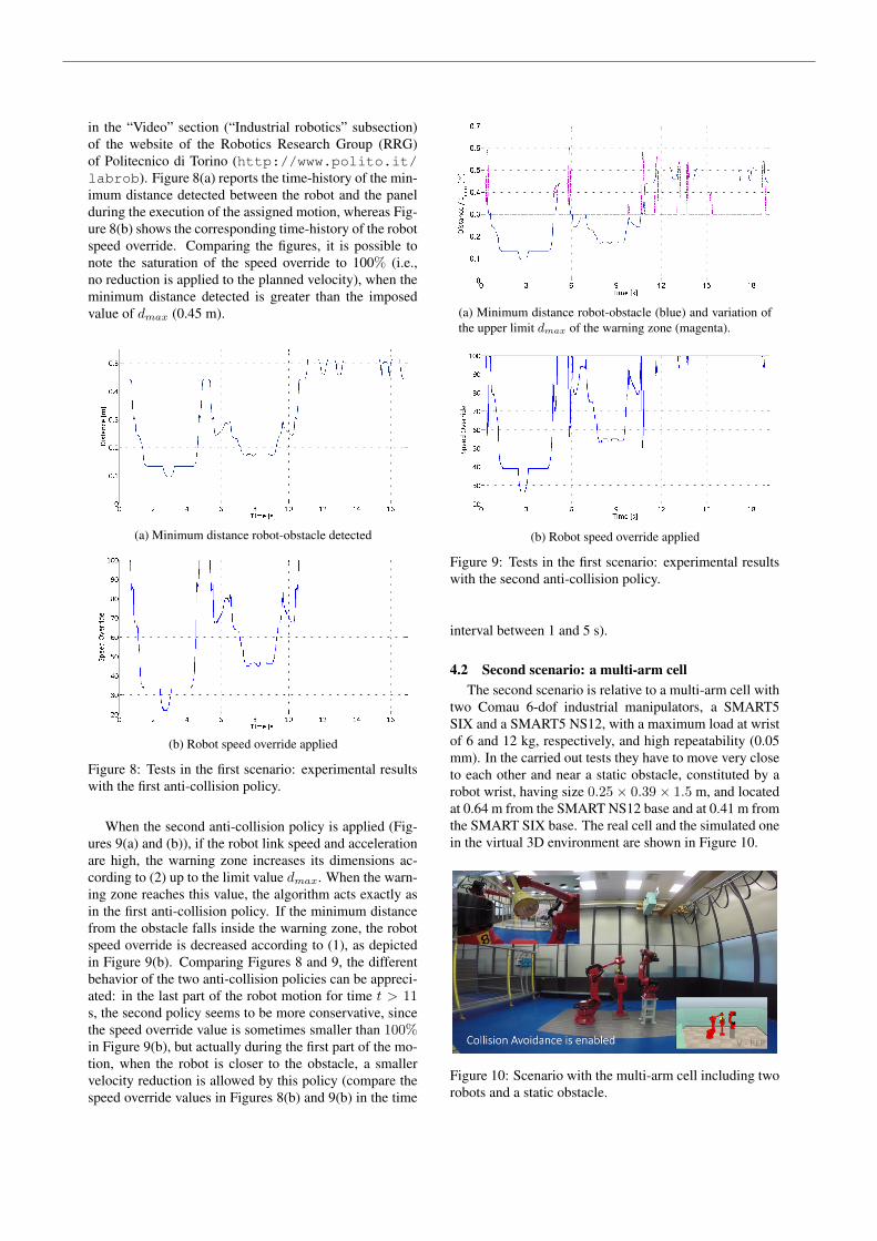
in the “Video” section (“Industrial robotics” subsection)of the website of the Robotics Research Group (RRG)of Politecnico di Torino (http://www.polito.it/labrob). Figure 8(a) reports the time-history of the min-imum distance detected between the robot and the panelduring the execution of the assigned motion, whereas Fig-ure 8(b) shows the corresponding time-history of the robotspeed override. Comparing the figures, it is possible tonote the saturation of the speed override to 100% (i.e.,no reduction is applied to the planned velocity), when theminimum distance detected is greater than the imposedvalue of dmax (0.45 m).
(a) Minimum distance robot-obstacle detected
(b) Robot speed override applied
Figure 8: Tests in the first scenario: experimental resultswith the first anti-collision policy.
When the second anti-collision policy is applied (Fig-ures 9(a) and (b)), if the robot link speed and accelerationare high, the warning zone increases its dimensions ac-cording to (2) up to the limit value dmax. When the warn-ing zone reaches this value, the algorithm acts exactly asin the first anti-collision policy. If the minimum distancefrom the obstacle falls inside the warning zone, the robotspeed override is decreased according to (1), as depictedin Figure 9(b). Comparing Figures 8 and 9, the differentbehavior of the two anti-collision policies can be appreci-ated: in the last part of the robot motion for time t > 11s, the second policy seems to be more conservative, sincethe speed override value is sometimes smaller than 100%in Figure 9(b), but actually during the first part of the mo-tion, when the robot is closer to the obstacle, a smallervelocity reduction is allowed by this policy (compare thespeed override values in Figures 8(b) and 9(b) in the time
(a) Minimum distance robot-obstacle (blue) and variation ofthe upper limit dmax of the warning zone (magenta).
(b) Robot speed override applied
Figure 9: Tests in the first scenario: experimental resultswith the second anti-collision policy.
interval between 1 and 5 s).
4.2 Second scenario: a multi-arm cellThe second scenario is relative to a multi-arm cell with
two Comau 6-dof industrial manipulators, a SMART5SIX and a SMART5 NS12, with a maximum load at wristof 6 and 12 kg, respectively, and high repeatability (0.05mm). In the carried out tests they have to move very closeto each other and near a static obstacle, constituted by arobot wrist, having size 0.25 × 0.39 × 1.5 m, and locatedat 0.64 m from the SMART NS12 base and at 0.41 m fromthe SMART SIX base. The real cell and the simulated onein the virtual 3D environment are shown in Figure 10.
Figure 10: Scenario with the multi-arm cell including tworobots and a static obstacle.
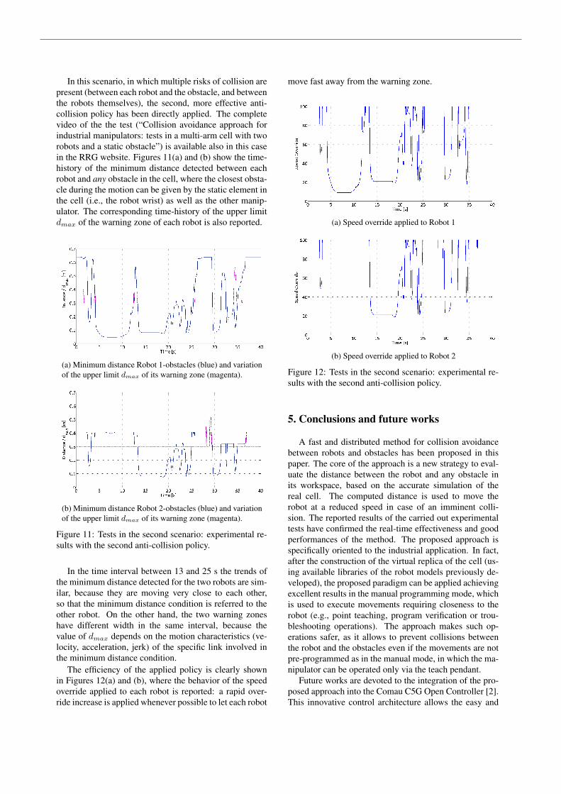
In this scenario, in which multiple risks of collision arepresent (between each robot and the obstacle, and betweenthe robots themselves), the second, more effective anti-collision policy has been directly applied. The completevideo of the the test (“Collision avoidance approach forindustrial manipulators: tests in a multi-arm cell with tworobots and a static obstacle”) is available also in this casein the RRG website. Figures 11(a) and (b) show the time-history of the minimum distance detected between eachrobot and any obstacle in the cell, where the closest obsta-cle during the motion can be given by the static element inthe cell (i.e., the robot wrist) as well as the other manip-ulator. The corresponding time-history of the upper limitdmax of the warning zone of each robot is also reported.
(a) Minimum distance Robot 1-obstacles (blue) and variationof the upper limit dmax of its warning zone (magenta).
(b) Minimum distance Robot 2-obstacles (blue) and variationof the upper limit dmax of its warning zone (magenta).
Figure 11: Tests in the second scenario: experimental re-sults with the second anti-collision policy.
In the time interval between 13 and 25 s the trends ofthe minimum distance detected for the two robots are sim-ilar, because they are moving very close to each other,so that the minimum distance condition is referred to theother robot. On the other hand, the two warning zoneshave different width in the same interval, because thevalue of dmax depends on the motion characteristics (ve-locity, acceleration, jerk) of the specific link involved inthe minimum distance condition.
The efficiency of the applied policy is clearly shownin Figures 12(a) and (b), where the behavior of the speedoverride applied to each robot is reported: a rapid over-ride increase is applied whenever possible to let each robot
move fast away from the warning zone.
(a) Speed override applied to Robot 1
(b) Speed override applied to Robot 2
Figure 12: Tests in the second scenario: experimental re-sults with the second anti-collision policy.
5. Conclusions and future works
A fast and distributed method for collision avoidancebetween robots and obstacles has been proposed in thispaper. The core of the approach is a new strategy to eval-uate the distance between the robot and any obstacle inits workspace, based on the accurate simulation of thereal cell. The computed distance is used to move therobot at a reduced speed in case of an imminent colli-sion. The reported results of the carried out experimentaltests have confirmed the real-time effectiveness and goodperformances of the method. The proposed approach isspecifically oriented to the industrial application. In fact,after the construction of the virtual replica of the cell (us-ing available libraries of the robot models previously de-veloped), the proposed paradigm can be applied achievingexcellent results in the manual programming mode, whichis used to execute movements requiring closeness to therobot (e.g., point teaching, program verification or trou-bleshooting operations). The approach makes such op-erations safer, as it allows to prevent collisions betweenthe robot and the obstacles even if the movements are notpre-programmed as in the manual mode, in which the ma-nipulator can be operated only via the teach pendant.
Future works are devoted to the integration of the pro-posed approach into the Comau C5G Open Controller [2].This innovative control architecture allows the easy and
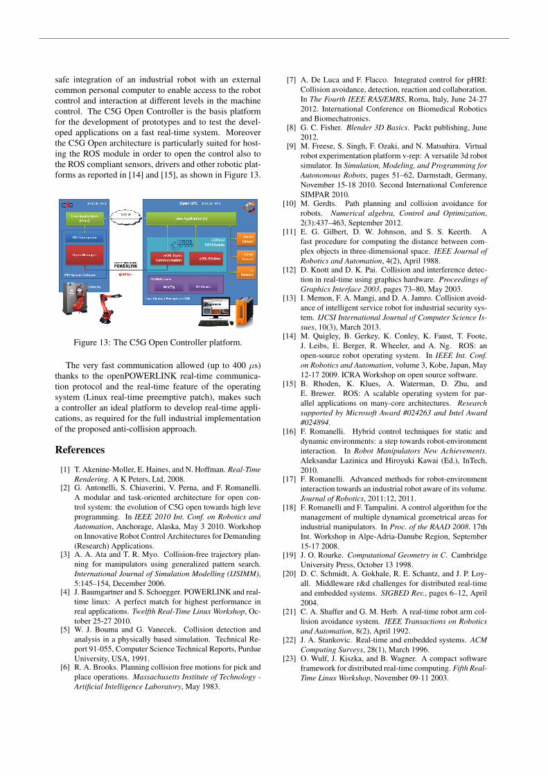
safe integration of an industrial robot with an externalcommon personal computer to enable access to the robotcontrol and interaction at different levels in the machinecontrol. The C5G Open Controller is the basis platformfor the development of prototypes and to test the devel-oped applications on a fast real-time system. Moreoverthe C5G Open architecture is particularly suited for host-ing the ROS module in order to open the control also tothe ROS compliant sensors, drivers and other robotic plat-forms as reported in [14] and [15], as shown in Figure 13.
Figure 13: The C5G Open Controller platform.
The very fast communication allowed (up to 400 µs)thanks to the openPOWERLINK real-time communica-tion protocol and the real-time feature of the operatingsystem (Linux real-time preemptive patch), makes sucha controller an ideal platform to develop real-time appli-cations, as required for the full industrial implementationof the proposed anti-collision approach.
References
[1] T. Akenine-Moller, E. Haines, and N. Hoffman. Real-TimeRendering. A K Peters, Ltd, 2008.
[2] G. Antonelli, S. Chiaverini, V. Perna, and F. Romanelli.A modular and task-oriented architecture for open con-trol system: the evolution of C5G open towards high leveprogramming. In IEEE 2010 Int. Conf. on Robotics andAutomation, Anchorage, Alaska, May 3 2010. Workshopon Innovative Robot Control Architectures for Demanding(Research) Applications.
[3] A. A. Ata and T. R. Myo. Collision-free trajectory plan-ning for manipulators using generalized pattern search.International Journal of Simulation Modelling (IJSIMM),5:145–154, December 2006.
[4] J. Baumgartner and S. Schoegger. POWERLINK and real-time linux: A perfect match for highest performance inreal applications. Twelfth Real-Time Linux Workshop, Oc-tober 25-27 2010.
[5] W. J. Bouma and G. Vanecek. Collision detection andanalysis in a physically based simulation. Technical Re-port 91-055, Computer Science Technical Reports, PurdueUniversity, USA, 1991.
[6] R. A. Brooks. Planning collision free motions for pick andplace operations. Massachusetts Institute of Technology -Artificial Intelligence Laboratory, May 1983.
[7] A. De Luca and F. Flacco. Integrated control for pHRI:Collision avoidance, detection, reaction and collaboration.In The Fourth IEEE RAS/EMBS, Roma, Italy, June 24-272012. International Conference on Biomedical Roboticsand Biomechatronics.
[8] G. C. Fisher. Blender 3D Basics. Packt publishing, June2012.
[9] M. Freese, S. Singh, F. Ozaki, and N. Matsuhira. Virtualrobot experimentation platform v-rep: A versatile 3d robotsimulator. In Simulation, Modeling, and Programming forAutonomous Robots, pages 51–62, Darmstadt, Germany,November 15-18 2010. Second International ConferenceSIMPAR 2010.
[10] M. Gerdts. Path planning and collision avoidance forrobots. Numerical algebra, Control and Optimization,2(3):437–463, September 2012.
[11] E. G. Gilbert, D. W. Johnson, and S. S. Keerth. Afast procedure for computing the distance between com-plex objects in three-dimensional space. IEEE Journal ofRobotics and Automation, 4(2), April 1988.
[12] D. Knott and D. K. Pai. Collision and interference detec-tion in real-time using graphics hardware. Proceedings ofGraphics Interface 2003, pages 73–80, May 2003.
[13] I. Memon, F. A. Mangi, and D. A. Jamro. Collision avoid-ance of intelligent service robot for industrial security sys-tem. IJCSI International Journal of Computer Science Is-sues, 10(3), March 2013.
[14] M. Quigley, B. Gerkey, K. Conley, K. Faust, T. Foote,J. Leibs, E. Berger, R. Wheeler, and A. Ng. ROS: anopen-source robot operating system. In IEEE Int. Conf.on Robotics and Automation, volume 3, Kobe, Japan, May12-17 2009. ICRA Workshop on open source software.
[15] B. Rhoden, K. Klues, A. Waterman, D. Zhu, andE. Brewer. ROS: A scalable operating system for par-allel applications on many-core architectures. Researchsupported by Microsoft Award #024263 and Intel Award#024894.
[16] F. Romanelli. Hybrid control techniques for static anddynamic environments: a step towards robot-environmentinteraction. In Robot Manipulators New Achievements.Aleksandar Lazinica and Hiroyuki Kawai (Ed.), InTech,2010.
[17] F. Romanelli. Advanced methods for robot-environmentinteraction towards an industrial robot aware of its volume.Journal of Robotics, 2011:12, 2011.
[18] F. Romanelli and F. Tampalini. A control algorithm for themanagement of multiple dynamical geometrical areas forindustrial manipulators. In Proc. of the RAAD 2008. 17thInt. Workshop in Alpe-Adria-Danube Region, September15-17 2008.
[19] J. O. Rourke. Computational Geometry in C. CambridgeUniversity Press, October 13 1998.
[20] D. C. Schmidt, A. Gokhale, R. E. Schantz, and J. P. Loy-all. Middleware r&d challenges for distributed real-timeand embedded systems. SIGBED Rev., pages 6–12, April2004.
[21] C. A. Shaffer and G. M. Herb. A real-time robot arm col-lision avoidance system. IEEE Transactions on Roboticsand Automation, 8(2), April 1992.
[22] J. A. Stankovic. Real-time and embedded systems. ACMComputing Surveys, 28(1), March 1996.
[23] O. Wulf, J. Kiszka, and B. Wagner. A compact softwareframework for distributed real-time computing. Fifth Real-Time Linux Workshop, November 09-11 2003.