Embed Size (px)
Citation preview
Page 1 of 20
Poles and Foundations for Overhead Contact Systems A Comparison of Advantages, Drawbacks and Costs
Between the Various Types
John P. Seferiadis, P.E.
MBTA
Charlestown, MA USA
Matthew S. Donahue, P.E.
HNTB Corporation
Chelmsford, MA USA
Paul F. White
HNTB Corporation
Chelmsford, MA USA
INTRODUCTION
Poles for overhead contact systems (OCS) are
composed of various types of materials including
steel, wood, fiberglass or concrete, and are available
in different shapes including round, square, multi-
sided or rectangular tubes, wide flange sections, solid
circular or lattice style. There are two basic types of
foundations; embedded or anchor base. For an
embedded pole foundation, the pole is either inserted
into a foundation hole with concrete poured around
the pole, or inserted directly into the earth if of wood,
concrete or fiberglass material. Anchor base
foundations utilize anchor bolts to transfer loads from
the pole to the supporting foundation. The anchor
bolts protrude from the top of the foundation and
mate with a base plate that is welded to the bottom of
a steel pole.
This paper discusses the merits and drawbacks
of each type and style of pole, the various
foundations available for supporting them, and the
cost differences between them as they relate to the
transit industry. It also presents maintenance and
safety concerns with the different styles of poles and
foundations, formulas used to calculate strength and
deflection of the pole, foundation diameter and
depths, and it further presents an historical account of
the origins of the poles and foundations discussed
herein.
Also discussed are creative solutions to
overcoming obstacles both underground and
overhead with the placement of poles and methods
used to strengthen and/or repair poles that are in
place.
Background
The first poles used to support electrical
overhead wires were wood and were used for a
telegraph line running between Washington D.C. and
Baltimore, Maryland that was constructed in 1844.
This was the first successful telegraph operation as
the electrical conductors were suspended above the
ground and attached to the pole by glass insulators.
The line was constructed by Samuel Morse with a
grant of $30,000 from the United States Congress.
The contract called for furnishing 700 straight and
sound chestnut posts with the bark in place and
having the dimensions of eight inches in diameter at
the butt and tapering to five or six inches at the top.
Out of the 700 poles, 680 were 24 feet and 20 were
30 feet long.
Wood poles are essentially the stem of trees with
bark and branches removed and the stem shaped.
Various species of trees are used for wood poles such
as Chestnut, Southern Yellow Pine, Douglas Fir, Jack
Pine, Lodgepole Pine, Western Red Cedar and
Pacific Silver Fir with various treatment methods to
prevent decay. Typical treatment methods are
creosote, pentachlorophenol, copper naphthenate, and
borates. Wood poles continue to be used for
supporting overhead contact lines on railways and
transit systems.
Granite poles were used in Switzerland for
supporting telegraph wires quite successfully and the
stone construction was used due to a shortfall of
timber (Fig.1). They were impervious to the
problems associated with wood and steel.
Page 2 of 20
Iron poles were used since the infancy of street
railways and one such installation was by the
Thomson-Houston Electric Company of Lynn,
Massachusetts (which later became the General
Electric Company). They supplied iron poles to the
West End Street Railway of Boston, Massachusetts,
for their first trolley line electrification in 1888. A
standard for iron pole types was proposed by
“American experts” in the street railway industry as
stated in the Engineering Journal, Volume 59, of
March 29, 1895 where five classes of iron or steel
poles were proposed for use in connection with well-
constructed trolley lines. Each class of pole was to be
31 feet long and set in the ground to a depth of 6 feet.
Loadings were as shown in Table 1.
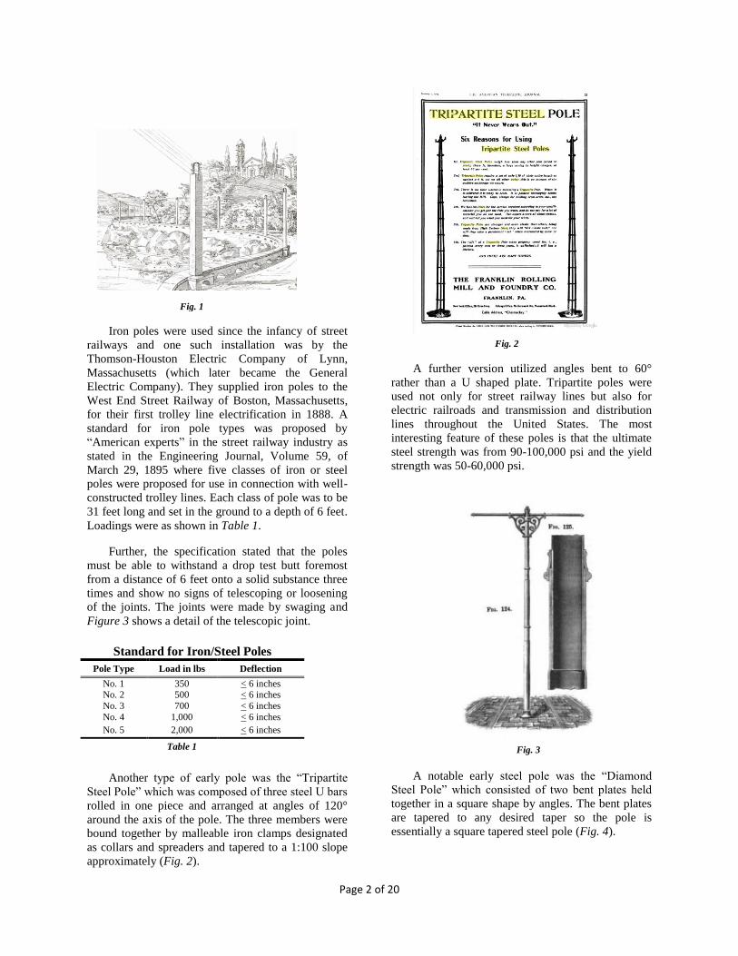
Further, the specification stated that the poles
must be able to withstand a drop test butt foremost
from a distance of 6 feet onto a solid substance three
times and show no signs of telescoping or loosening
of the joints. The joints were made by swaging and
Figure 3 shows a detail of the telescopic joint.
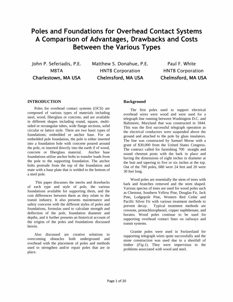
Another type of early pole was the “Tripartite
Steel Pole” which was composed of three steel U bars
rolled in one piece and arranged at angles of 120°
around the axis of the pole. The three members were
bound together by malleable iron clamps designated
as collars and spreaders and tapered to a 1:100 slope
approximately (Fig. 2).
A further version utilized angles bent to 60°
rather than a U shaped plate. Tripartite poles were
used not only for street railway lines but also for
electric railroads and transmission and distribution
lines throughout the United States. The most
interesting feature of these poles is that the ultimate
steel strength was from 90-100,000 psi and the yield
strength was 50-60,000 psi.
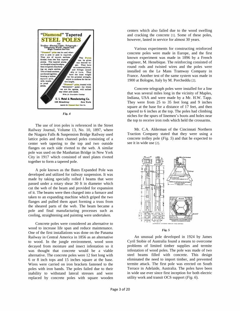
A notable early steel pole was the “Diamond
Steel Pole” which consisted of two bent plates held
together in a square shape by angles. The bent plates
are tapered to any desired taper so the pole is
essentially a square tapered steel pole (Fig. 4).
Standard for Iron/Steel Poles
Pole Type Load in lbs Deflection
No. 1 350 < 6 inches No. 2 500 < 6 inches
No. 3 700 < 6 inches
No. 4 1,000 < 6 inches
No. 5 2,000 < 6 inches
Table 1 Fig. 3
Fig. 1
Fig. 2
Page 3 of 20
The use of iron poles is referenced in the Street
Railway Journal, Volume 13, No. 10, 1897, where
the Niagara Falls & Suspension Bridge Railway used
lattice poles and then channel poles consisting of a
center web tapering to the top and two outside
flanges on each side riveted to the web. A similar
pole was used on the Manhattan Bridge in New York
City in 1917 which consisted of steel plates riveted
together to form a tapered pole.
A pole known as the Bates Expanded Pole was
developed and utilized for railway suspension. It was
made by taking specially rolled I beams that were
passed under a rotary shear 30 ft in diameter which
cut the web of the beam and provided for expansion
of it. The beams were then charged into a furnace and
taken to an expanding machine which griped the two
flanges and pulled them apart forming a truss from
the sheared parts of the web. The beam became a
pole and final manufacturing processes such as
cooling, straightening and painting were undertaken.
Concrete poles were considered an alternative to
wood to increase life span and reduce maintenance.
One of the first installations was done on the Panama
Railway in Central America in 1856 as an alternative
to wood. In the jungle environment, wood soon
decayed from moisture and insect infestation so it
was thought that concrete would be a viable
alternative. The concrete poles were 12 feet long with
6 or 8 inch tops and 15 inches square at the base.
Wires were carried on iron brackets fastened to the
poles with iron bands. The poles failed due to their
inability to withstand lateral stresses and were
replaced by concrete poles with square wooden
centers which also failed due to the wood swelling
and cracking the concrete [1]. Some of these poles,
however, lasted in service for almost 30 years.
Various experiments for constructing reinforced
concrete poles were made in Europe, and the first
known experiment was made in 1896 by a French
engineer, M. Henebique. The reinforcing consisted of
round rods and twisted wires and the poles were
installed on the Le Mans Tramway Company in
France. Another test of the same system was made in
1900 at Bologne, Italy by M. Porcheddu [2].
Concrete telegraph poles were installed for a line
that was several miles long in the vicinity of Maples,
Indiana, USA and were made by a Mr. H.W. Tapp.
They were from 25 to 35 feet long and 9 inches
square at the base for a distance of 17 feet, and then
tapered to 6 inches at the top. The poles had climbing
niches for the spurs of linemen’s boots and holes near
the top to receive iron rods which held the crossarms.
Mr. C.A. Alderman of the Cincinnati Northern
Traction Company stated that they were using a
concrete trolley pole (Fig. 5) and that he expected to
see it in wide use [2].
An unusual pole developed in 1924 by James
Cyril Stobie of Australia found a means to overcome
problems of limited timber supplies and termite
infestation of wood poles. The pole was made of two
steel beams filled with concrete. This design
eliminated the need to import timber, and prevented
termite attack. The first pole was erected on South
Terrace in Adelaide, Australia. The poles have been
in wide use ever since first inception for both electric
utility work and transit OCS support (Fig. 6).
Fig. 5
Fig. 4

Page 4 of 20
A most notable concrete pole was used along
Van Ness Avenue in San Francisco, California where
the poles supported street lights and overhead trolley
span wires since installation in 1914. This was
constructed of cast reinforced concrete, a cast iron
ornamental cap, cast iron removable base and made
with a decidedly ornamental flair that is classic. The
poles were part of the H streetcar line constructed to
link neighborhoods with the Panama-Pacific
International Exposition at Harbor View (now
Marina District) [3]. These poles will soon be retired
from use with the rebuilding of Van Ness Avenue
starting in 2016 (Fig. 7).
It was reported in Railway Engineering and
Maintenance of Way, June 1911 that a high-tension
transmission line between Livet and Grenoble, in
France installed poles of thoroughly dried round
wood and covered with a stiff concrete paste so that
the wood pole was the core. 3/16” diameter round
rods were wound in a spiral with longitudinally round
rods tied to them. The diameter of the longitudinal
rods varied from 1/16” to 1/8” depending upon the
length and strength desired.
In 1927, Henry Ford electrified part of the
Detroit Toledo & Ironton railroad from River Rouge
to Carleton, Michigan and constructed reinforced
concrete catenary supporting structures. These were
extremely sturdy structures as they were spaced 300
feet apart. Many are still standing today and were so
rugged that it took demolition crews two days to
demolish each structure. Each structure contained 95
cubic yards of concrete and 257 feet of rebar (Fig. 8).
POLE TYPES FOR TRANSIT WORK
The most common types of poles are presented
herein for discussion. Tubular tapered steel poles are
the most widely used today for transit work. Wide
flange poles are the next most widely used with
straight tube, sectional, and wood following. Prior to
the light rail renaissance, embedded poles were the
norm but the majority in use presently is the anchor
base type. Some transit systems continue the use of
direct embedment as a less expensive and more
maintainable type of pole installation.
Wood Poles
Wood pole standards of construction and
strength are shown in ANSI Standard O5.1-2008
where the permitted stress level of various species
must be determined by multiplying the designated
fiber strength by the factors shown on Table 261-1 of
the NESC. Wood poles are classified by their length,
top circumference and bottom circumference
measured 6 feet from the butt end. Lengths vary in 5
foot increments such as 25, 30, 35, 40, etc., to 110
feet and circumferences in 2 inch increments such as
15, 17, 19, etc. Each class of pole has a minimum tip
circumference. A Class 1 pole, for example, has a 27
Fig. 6
Fig. 7
Fig. 8

Page 5 of 20
inch minimum top circumference, but greater top
circumferences are available.
Pole classification numbers have a requirement
for the load the pole must be able to withstand 2 feet
from the top and this is shown in Table 2. A pole’s
height and class are typically abbreviated as “30-6”
which is a 30 ft long-Class 6 pole. A convenient
formula to determine the resisting moment is:
Resisting moment = 0.000264 𝑓 c3 lb- ft
Where 𝑓 = ultimate fiber stress in bending (lbs/sq
inch)
c = pole circumference 6 feet from the butt (inches)
As an example, a Class 1 southern yellow pine
pole 30 feet long with a minimum top and bottom
circumference of 27 inches and 37.5 inches
respectively has a resisting moment of 104,650 lb-ft.
[8]. Deflection of wood poles can be countered by
raking them away from the line of pull. If the pole
can be back guyed or head guyed, a pole of lesser
strength can be used and the raking of it can be
foregone but the compressive strength of the pole
must withstand the forces imparted into it from the
guy.
Wood poles are the least expensive type of pole
to purchase and an installation using a Southern
Yellow Pine Class 2 pole, 30 feet long costs
approximately ~$370.00. A mechanized pole setting
crew can install a pole in one hour. Table 6 provides
a comparison of material pole costs. A 30-2 pole, set
6 feet in the ground with a span wire attachment
height of 22 feet can safely withstand a side pull of
3,700 lbs. Rake of cantilevered wood poles for transit
use should be 12 inches in 24 feet for span wires, and
6 inches in 24 feet for bracket arms according to the
American Transit Association standard D14 Direct
Suspension Overhead Construction.
Additional cost savings are possible with the use
of wood poles if joint-use is permitted. In this
scenario, utilities can own the pole and allow other
utilities or transit authorities to attach to it or have
rental or attachment rights agreements. Joint-use
poles require close coordination between the pole
owner and the tenants when maintenance is required.
Typical wood poles with treatment can last up to 35
years.
Steel Poles
For the purpose of this paper, steel pole types
shall include tubular straight, tubular sectional,
tubular tapered, and wide flange beams. The strength
of these poles is dependent upon their yield strength
and cross sectional area. IEEE Standard for
Supporting Structures for Overhead Contact Systems
for Transit Systems outlines the construction and
performance criteria for sectional and tapered tubular
steel poles. ASTM standards define the type of steel
and strength.
Tubular
Typically for transit work, tubular straight and
sectional poles are made with pipe conforming to
ASTM A500 Gr. C, where the yield strength of steel
is a minimum of 50,000 psi. A recent ASTM
standard for tube construction, A1085, has been
issued and specifically states higher yield strengths.
Some transit projects have used tubular poles made
of Corten® steel to increase longevity from corrosion
but the most common method for corrosion
protection is hot dip galvanizing per ASTM A213
and A153.
Tapered tubular poles are manufactured with a
process that forms the pole over a hardened steel
mandrel which increases the yield strength to a
minimum of 55,000 psi. Other formed tapered poles
with multi sides also have similar yield strengths.
Higher strength steel yields are possible with some
tapered poles being made to a strength of 60,000 to
70,000 psi at yield.
They can also be formed using a brake press
where the flat sheet of steel is bent to form a multi-
sided tube. Steel strengths are similar and the
quantity of sides determines their roundness.
A distinct advantage of round poles made of
tubular steel, concrete, or wood is that the strength is
the same in any direction due to the symmetry of the
Classification for Wood Poles Pole
Class
ANSI
O5.1
Horizontal
Load in lbs
Pole Class
ANSI 05.1
Horizontal
Load in lbs
H6 11,400 3 3,000 H5 10,000 4 2,400
H4 8,700 5 1,900
H3 7,500 6 1,500
H2 6,400 7 1,200
H1 4,400 8 Not Used
1 4,500 9 740
2 3,700 10 370
Table 2
Page 6 of 20
shape. Bending stresses are distributed consistently
regardless of the direction of the applied load. They
also offer greatly increased resistance to torsion than
other structural shapes due to the greater rigidity
characteristic of the tubular design
Existing tubular poles that are direct embedded
into the earth can be reinforced for additional
strength or resistance to deflection by inserting re-bar
and concrete into its interior. Strengthening is more
difficult with anchor base poles. The base plate
typically has a hole in the center for condensation
drainage that needs to be blocked while the concrete
cures.
Wide Flange
Wide flange poles have been made to ASTM
A36 standards but are now being specified to ASTM
A572 or ASTM A992 standards where the yield
strength is 50,000 psi. These typically have a higher
strength to weight ratio than tubular poles and are
therefore generally less expensive. Wide flange poles
have two varying strength axes: the X-X direction
and the Y-Y direction, each with a different section
modulus and thus a different allowable bending
moment and deflection. The X-X axis provides the
greatest resistance to bending due to the increased
moment of inertia of the flanges about the neutral
axis. Having only one strong direction for pull can be
restrictive.
Wide flange poles can be reinforced for strength
with plates or angles welded or bolted to the flanges.
This is done quite frequently in Europe and also with
Amtrak as a way to minimize weight and cost while
obtaining additional strength. If the loads increase on
an existing pole, the pole can be retrofitted with
plates or angles to strengthen it and avoid a
potentially costly pole replacement.
Concrete Poles
Concrete poles have become common place in
the electrical industry and used world-wide in
transmission, distribution, and electric railways and
transit. A standard was developed under the guidance
of the ATA as standard D108 for cast reinforced
concrete poles but was discontinued in 1941 due to
the decreasing use of this pole type at that period in
time. Current pole construction typically can use
hollow reinforced spun cast poles or static cast, both
of varying diameters and lengths. Spun cast poles
have higher compressive strength than static cast
because the concrete is consolidated during the
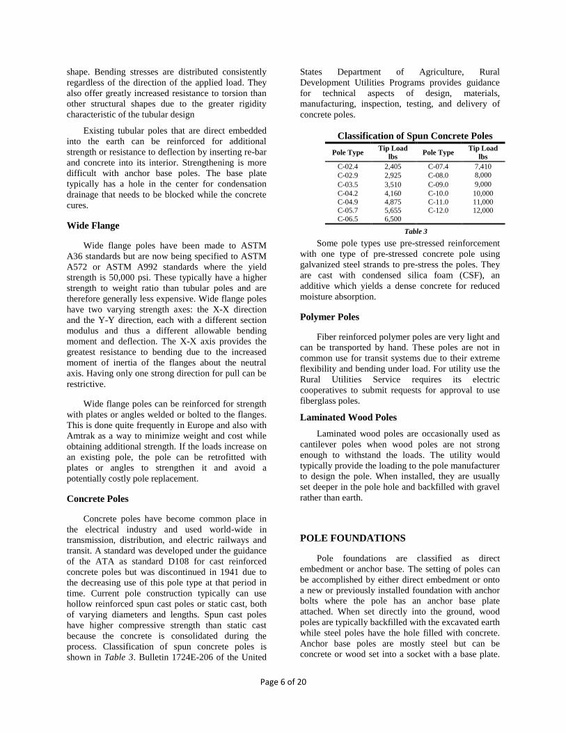
process. Classification of spun concrete poles is
shown in Table 3. Bulletin 1724E-206 of the United
States Department of Agriculture, Rural
Development Utilities Programs provides guidance
for technical aspects of design, materials,
manufacturing, inspection, testing, and delivery of
concrete poles.
Some pole types use pre-stressed reinforcement
with one type of pre-stressed concrete pole using
galvanized steel strands to pre-stress the poles. They
are cast with condensed silica foam (CSF), an
additive which yields a dense concrete for reduced
moisture absorption.
Polymer Poles
Fiber reinforced polymer poles are very light and
can be transported by hand. These poles are not in
common use for transit systems due to their extreme
flexibility and bending under load. For utility use the
Rural Utilities Service requires its electric
cooperatives to submit requests for approval to use
fiberglass poles.
Laminated Wood Poles
Laminated wood poles are occasionally used as
cantilever poles when wood poles are not strong
enough to withstand the loads. The utility would
typically provide the loading to the pole manufacturer
to design the pole. When installed, they are usually
set deeper in the pole hole and backfilled with gravel
rather than earth.
POLE FOUNDATIONS
Pole foundations are classified as direct
embedment or anchor base. The setting of poles can
be accomplished by either direct embedment or onto
a new or previously installed foundation with anchor
bolts where the pole has an anchor base plate
attached. When set directly into the ground, wood
poles are typically backfilled with the excavated earth
while steel poles have the hole filled with concrete.
Anchor base poles are mostly steel but can be
concrete or wood set into a socket with a base plate.
Classification of Spun Concrete Poles
Pole Type Tip Load
lbs Pole Type
Tip Load
lbs
C-02.4 2,405 C-07.4 7,410
C-02.9 2,925 C-08.0 8,000
C-03.5 3,510 C-09.0 9,000
C-04.2 4,160 C-10.0 10,000
C-04.9 4,875 C-11.0 11,000 C-05.7 5,655 C-12.0 12,000
C-06.5 6,500
Table 3
Page 7 of 20
The base plate is mounted onto anchor bolts but a
foundation can be made with the socket cast-in-place
and the pole set into it.
Prefabricated foundations can be used and they
have a socket in a donut hole fashion for inserting the
pole into it after the foundation has been installed. It
can also be done with anchor bolts protruding for
attachment of anchor base poles.
Direct Embedment
Wood and concrete poles are typically set
directly into an excavated hole in the ground with the
removed fill put back in and tamped to compact the
fill. For extreme loadings or poor soil conditions, the
pole should be keyed and heeled or concrete may be
used as fill. A rule of thumb for the depth setting of
wood poles is 10% of the pole length plus 2 feet.
Tables 5 through 8 of ANSI O5.1 list the
approximate groundline distance from the butt for
different lengths of poles and is very close to the “10
and 2” rule. An alternative to the rule of thumb is the
use of a nomograph design aid by AASHTO DTS
that is based on the equivalent horizontal load,
allowable soil bearing pressure, and width of the pole
at embedment.
Steel poles should be set in concrete for
maximum foundation strength. They have historically
been set directly into the pole hole with concrete
poured in without reinforcing rods. The direct contact
with earth provides an excellent electrical earth
ground. Both round and wide flange poles have been
set in this manner. A concrete pad that the pole rests
on has also been used. However, a separate
grounding arrangement is required for this type of
installation.
When the open area between the pole and the
excavated hole wall becomes large, the addition of
foundation reinforcing should be considered.
Reinforcing rods inserted between the pole and the
hole wall will ensure concrete stability and rigidity,
and also prevent concrete cracking. The standard
method is to use a circular cage of horizontal and
longitudinal bars which sits between the pole and the
excavated hole wall. Where a steel caisson of
sufficient strength is employed, reinforcing rods may
not be needed.
Another method of embedded pole foundation
uses an interior pipe set into the hole to which
concrete is poured between it and the hole wall in a
donut fashion. The pole is set into the inner pipe and
then concrete poured in and the pipe acts as
reinforcement.
When poles are set in city streets with granite
curb stone for the foundation to bear against, the
foundation is more resistant to rotation as it has a
substantial bearing surface to rest against, thereby
requiring less depth or width for the foundation.
When set with no curb or top bearing member, a key
of substantial material such as granite curbing or a
reinforced concrete slab can be installed to provide
additional bearing surface if required.
Anchor Base
Anchor base foundations consist of anchor bolts
embedded in a concrete foundation typically with
reinforcing. The anchor bolts vary in diameter and
depth according to the load that will be applied to
them. For transit work, 4 anchor bolts are typically
used although more can be used if warranted. The
base plate for the pole is usually above grade and the
anchor bolts exposed. Some agencies require a layer
of grout between the top of foundation and the
bottom of the base plate. Another method of pole
mounting on the foundation is to have the top of the
foundation below grade so that the pole anchor plate
and part of the pole is set into the foundation and
concrete is poured over it giving the appearance that
the pole is embedded. Leveling nuts are often used to
set a pole to the proper vertical alignment and rake.
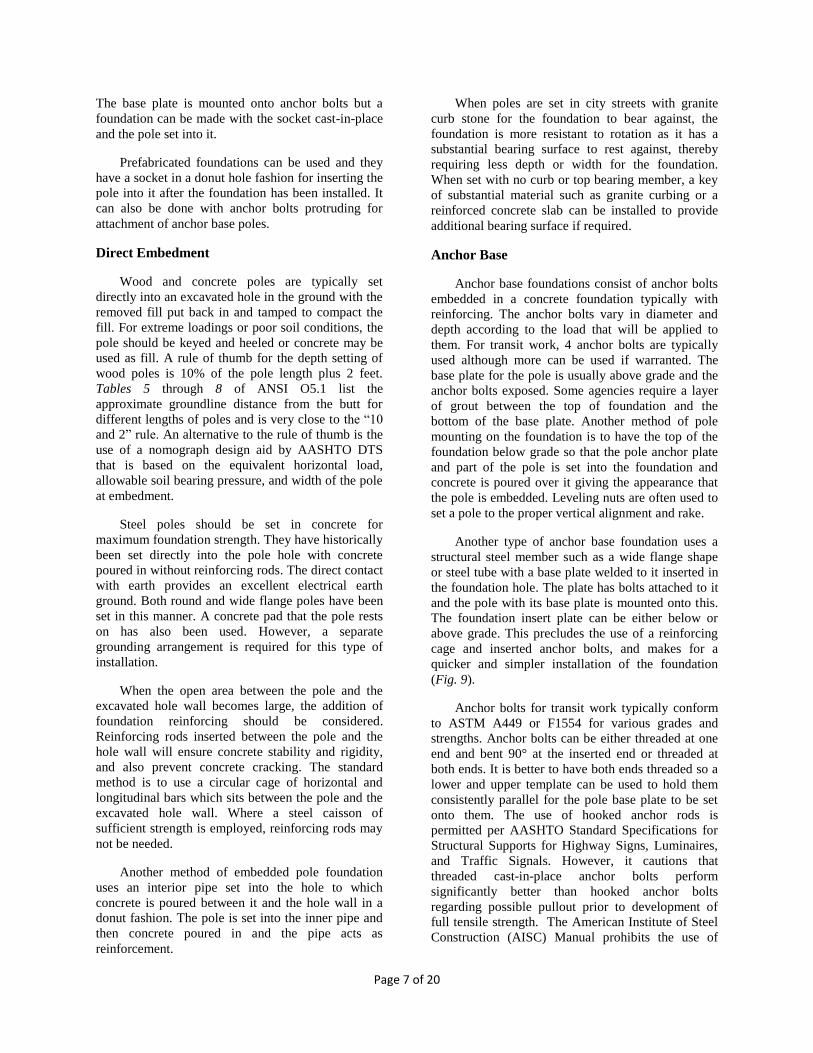
Another type of anchor base foundation uses a
structural steel member such as a wide flange shape
or steel tube with a base plate welded to it inserted in
the foundation hole. The plate has bolts attached to it
and the pole with its base plate is mounted onto this.
The foundation insert plate can be either below or
above grade. This precludes the use of a reinforcing
cage and inserted anchor bolts, and makes for a
quicker and simpler installation of the foundation
(Fig. 9).
Anchor bolts for transit work typically conform
to ASTM A449 or F1554 for various grades and
strengths. Anchor bolts can be either threaded at one
end and bent 90° at the inserted end or threaded at
both ends. It is better to have both ends threaded so a
lower and upper template can be used to hold them
consistently parallel for the pole base plate to be set
onto them. The use of hooked anchor rods is
permitted per AASHTO Standard Specifications for
Structural Supports for Highway Signs, Luminaires,
and Traffic Signals. However, it cautions that
threaded cast-in-place anchor bolts perform
significantly better than hooked anchor bolts
regarding possible pullout prior to development of
full tensile strength. The American Institute of Steel
Construction (AISC) Manual prohibits the use of
Page 8 of 20
hooked anchor rods in tension, and cites limited
pullout strength of hooked rods.
Pole foundations with anchor bolts are subject to
construction accidents where equipment can strike
them causing bending. Re-bending them straight can
cause stress fractures as the type and grade of anchor
bolt may not be known. Any repairs to straighten the
bolts should be made according to AISC guidelines.
In the event rock is encountered while drilling, a
rock socket foundation can be installed. The driller
will switch drill bits to a smaller diameter coring bit.
The first few feet of rock are considered incompetent,
and the minimum rock socket depth is typically 5 feet
into competent rock. However, additional drilling
depth is often required to provide enough overlap
between the rebar cages of varying diameters. This
development length ensures that the stresses in the
rebar are transferred to the concrete using the bond
between the steel and concrete. Rock socket
foundations are significantly more expensive than
traditional foundation installations and drilling is a
much slower process.
MAINTENANCE AND SAFETY
CONCERNS
Wood Pole Repair
About 1900 the practice of using concrete bases
around the decayed butts of wooden poles became
quite common. This practice continues today where
fiberglass sheets impregnated with resins are used to
compensate for rot and decay and provides a very
efficient method for wood pole butt repair. Another
technique used is to replace a portion of the lower
wood pole with a concrete or wood pole. In this
method, the bottom of the wood pole is cut free from
the top portion and removed while pole derrick trucks
hold the top in place. The concrete bottom portion
called a modular pole is inserted in the same hole and
the top portion attached to the concrete portion
through a steel sleeve. Total time takes around 90
minutes to install an 18 foot module [5].
Still another method for wood pole repair is to
use a reinforcing clamp that clamps around the pole
and is partially buried in the pole hole.
Steel Pole Repair
Steel sleeves for round poles and flat plates for
wide flange poles are typically used for repairs.
Historically, one method of reinforcing tubular steel
poles because of corrosion was to insert a
commercially available reinforcing cage made of
high strength carbon steel twisted bars into the
interior of the pole and fill the void with concrete.
The cage had a concrete iron base attached to it at the
factory where they were assembled but at the top a
hooked cap temporarily confined the upper ends of
the rods to allow the cage to pass through the narrow
upper section of the pole. Upon withdrawal of the cap
the bars flared out but did not touch the pole walls as
shims were attached to them. At this point, concrete
was pumped into the pole to cover the rods. This
method was devised and employed by the New York
Pole Company. This procedure significantly
increased the strength of the pole which compensated
for the loss of cross sectional area due to corrosion
[4].
During the construction of trackless trolley lines
in the United States in the 1930’s to 1950’s, existing
steel trolley poles supporting streetcar overhead were
similarly reinforced to increase their strength.
Reinforcing rods and concrete were put into the poles
which substantially increased the strength of the pole.
Of note is a method used in San Francisco where they
inserted used cable car slot zee angles as reinforcing
with the concrete.
A novel method by the Ohio Brass Company for
exterior repair of tubular poles at the ground line was
the use of a split sleeve that was placed around the
pole butt at the ground line in a hinge fashion. The
sleeve was larger than the pole base diameter so that
after installation, concrete grout could be poured into
the void sealing the sleeve to the pole thus arresting
further corrosion.
Figure 9
Page 9 of 20
Tubular poles are usually fabricated with a
corrosion collar around the butt section at the ground
line that acts as a sacrificial member. A collar can
also be used to make a repair to an existing steel pole
by welding a sleeve around the pole above and below
grade when the pole is severely corroded. The collar
can be attached to an existing pole by using a split
sleeve and welding circumferentially at its base, top
and seams.
Corrosion of the interior of tubular poles has
been a concern especially for older poles protected
with only paint. Interior corrosion can cause
significant loss of cross sectional area over time and
the inside of the poles should be periodically
checked. Corrosion of the joints where water collects
is a problem on very old sectional poles. New
construction uses either beveled joints or welds for
water shedding. If the joint area is corroded, it can be
cleaned to bright metal by grinding and then welded
in place with a bevel weld. The repaired area should
then be coated or painted to prevent further corrosion.
Corten® steel has been used for transit poles and
this material provides weathering characteristics that
protect the material below the surface. Once
weathered, the surface has a dark rust color that can
stain surrounding surfaces such as concrete
foundations and sidewalks. A particular problem with
Corten® steel is that it can continue to corrode and
essentially rust away. Use of this type of steel with
transit poles may require special welding materials
and techniques to ensure that the weld material
weathers at the same rate as the steel being welded.
The material in itself is not rustproof and if water is
trapped behind a fitting or clamp, accelerated
corrosion and loss of metal will occur so provision
for either drainage of water or prevention of moisture
accumulation must be considered. This type of steel
is sensitive to humid sub-tropical conditions and
areas where there is a high sea salt content in the air.
The Omni Coliseum in Atlanta, Georgia, constructed
of Corten® steel, never stopped corroding due to the
high humidity of the area and had large holes
developed in the structure. It was demolished 25
years after construction.
Repairs to the material can be made by welding
patches or fillers if the corrosion is localized and
small. Full scale corrosion of the pole would warrant
complete replacement.
Anchor Base Pole Repair
Anchor base poles are particularly vulnerable to
corrosion at the anchor bolts and where snow, ice and
deicing salts are encountered, accelerated corrosion
can occur. Where anchor bolts are exposed under the
base plate, inspections can be conducted and
remedial action taken if corrosion is taking place. The
anchor bolts should be thoroughly cleaned to remove
all rust and then painted with an appropriate type of
paint to impede further corrosion.
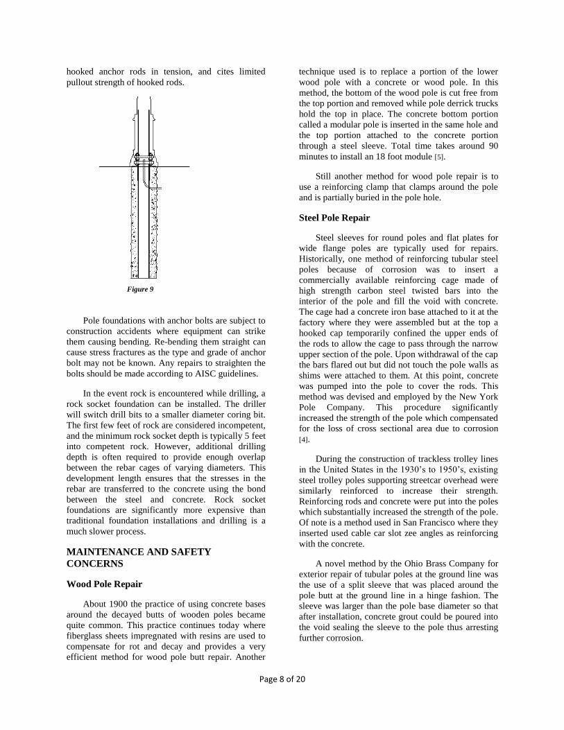
Placing grout between the bottom of the base
plate to the foundation top and around the anchor
bolts does not fully protect the bolts. The grouting
method has a tendency to crack, allow moisture in
and then trap it further causing accelerated corrosion.
Figure 10 shows the effects of grouting the base
plate.
A common malady of anchor base poles is the
anchor bolts in the foundation being bent prior to the
pole being set on it. A bent anchor bolt can be
straightened depending on the severity of the bend
and the type of anchor bolt used. Typically anchor
base pole foundations use one of two types of anchor
bolts designated by ASTM standards; F1554 or
A449. Type F1554 Grade 36 anchor bolts less than
1” dia. can be cold bent to their straight position if
not bent more than 45 degrees. For diameters greater
than 1 inch, the rod has to be heated to 1,200° F to
make bending easier. Bending should be done using a
rod bending device called a hickey. After bending,
the rods should be visually inspected for cracks. If
there is concern about the tensile strength of the
anchor rod, the rod can be load tested. Type A449
should not be bent as it is more brittle and stress
cracks will most likely result from the bending and
compromise the structural integrity of the anchor
bolt.
In the event an anchor bolt must be replaced due
to deformation or corrosion, the damaged bolt should
Figure 10
Page 10 of 20
be cut flush with the top of the foundation. A new
hole can then be drilled adjacent to the existing
anchor bolt, and an anchor rod can be epoxied in the
hole. The column base plate will likely require field
drilling to accept the new anchor rod. An alternative
solution is to core around the existing bolt to an
appropriate depth, clean and thread the rod, and
install an extension to the anchor rod using a
coupling. A final and more expensive option is to
install a new foundation next to the existing
foundation. The existing pole can either be
transferred to the new foundation, or a new pole can
be installed. If necessary the old pole can then be
removed in addition to part of the old foundation to
an appropriate level below grade. [7].
An alternative to drilling the pole base plate
which may not have sufficient space for the
repositioned hole is to have a sub-base plate with a
hole pattern matching the new hole pattern of the
foundation and added bolts for attaching the pole
base plate.
OVERCOMING INSTALLATION OBSTACLES
Various obstacles can be encountered during the
planning and installation phases of an OCS line
during line construction such as below grade utilities
or overhead structures. Poles are usually designed for
the particular situation or obstruction. One such
method where there is an obstruction directly over
the pole and the pole cannot be relocated is to bend
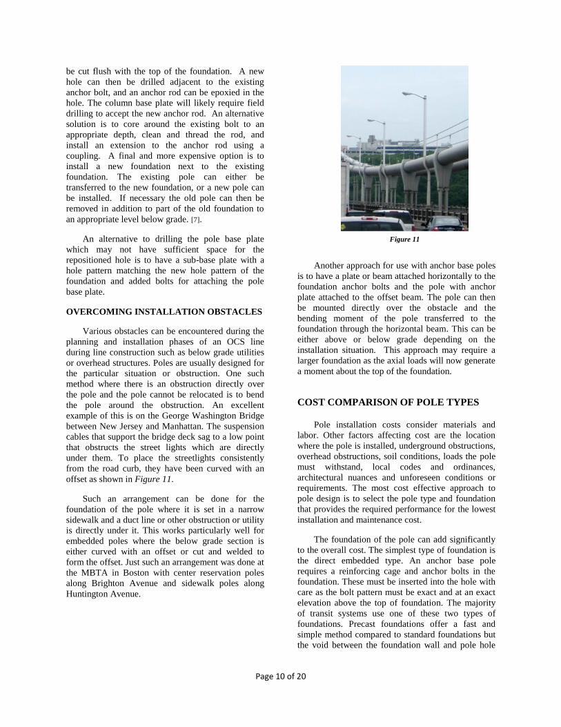
the pole around the obstruction. An excellent
example of this is on the George Washington Bridge
between New Jersey and Manhattan. The suspension
cables that support the bridge deck sag to a low point
that obstructs the street lights which are directly
under them. To place the streetlights consistently
from the road curb, they have been curved with an
offset as shown in Figure 11.
Such an arrangement can be done for the
foundation of the pole where it is set in a narrow
sidewalk and a duct line or other obstruction or utility
is directly under it. This works particularly well for
embedded poles where the below grade section is
either curved with an offset or cut and welded to
form the offset. Just such an arrangement was done at
the MBTA in Boston with center reservation poles
along Brighton Avenue and sidewalk poles along
Huntington Avenue.
Another approach for use with anchor base poles
is to have a plate or beam attached horizontally to the
foundation anchor bolts and the pole with anchor
plate attached to the offset beam. The pole can then
be mounted directly over the obstacle and the
bending moment of the pole transferred to the
foundation through the horizontal beam. This can be
either above or below grade depending on the
installation situation. This approach may require a
larger foundation as the axial loads will now generate
a moment about the top of the foundation.
COST COMPARISON OF POLE TYPES
Pole installation costs consider materials and
labor. Other factors affecting cost are the location
where the pole is installed, underground obstructions,
overhead obstructions, soil conditions, loads the pole
must withstand, local codes and ordinances,
architectural nuances and unforeseen conditions or
requirements. The most cost effective approach to
pole design is to select the pole type and foundation
that provides the required performance for the lowest
installation and maintenance cost.
The foundation of the pole can add significantly
to the overall cost. The simplest type of foundation is
the direct embedded type. An anchor base pole
requires a reinforcing cage and anchor bolts in the
foundation. These must be inserted into the hole with
care as the bolt pattern must be exact and at an exact
elevation above the top of foundation. The majority
of transit systems use one of these two types of
foundations. Precast foundations offer a fast and
simple method compared to standard foundations but
the void between the foundation wall and pole hole
Figure 11
Page 11 of 20
must be sufficiently filled and tamped to prevent
foundation movement.
Not all pole and foundation types are feasible for
each application. Sometimes there are special
requirements restricting use of certain pole and
foundation types. City streets in shopping districts
require different attention than private rights of way
in rural settings. A city installation may require
ornate tubular steel poles of different colors while
rights of way could allow the use of wide flange
poles or even wood poles. In order to achieve an
equal cost comparison for the various types of poles
and foundations, ideal conditions are assumed and
each pole must be sized for the same loading and soil
conditions. The deflection for steel poles has been
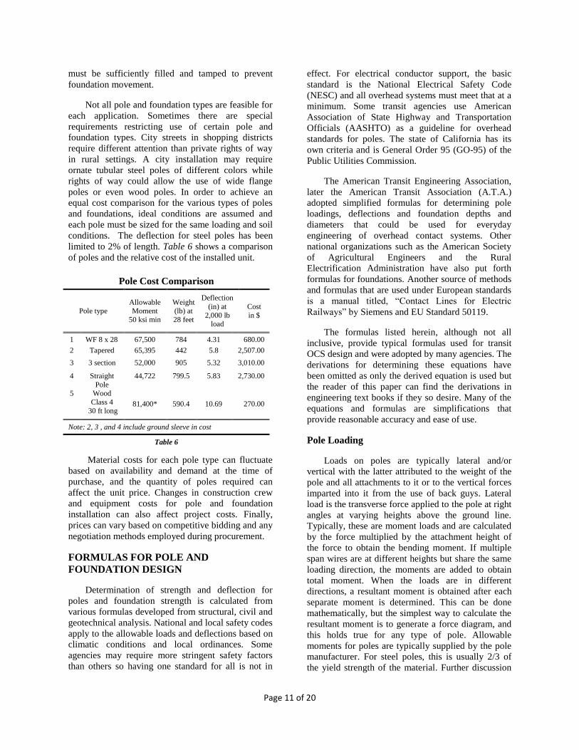
limited to 2% of length. Table 6 shows a comparison
of poles and the relative cost of the installed unit.
Material costs for each pole type can fluctuate
based on availability and demand at the time of
purchase, and the quantity of poles required can
affect the unit price. Changes in construction crew
and equipment costs for pole and foundation
installation can also affect project costs. Finally,
prices can vary based on competitive bidding and any
negotiation methods employed during procurement.
FORMULAS FOR POLE AND
FOUNDATION DESIGN
Determination of strength and deflection for
poles and foundation strength is calculated from
various formulas developed from structural, civil and
geotechnical analysis. National and local safety codes
apply to the allowable loads and deflections based on
climatic conditions and local ordinances. Some
agencies may require more stringent safety factors
than others so having one standard for all is not in
effect. For electrical conductor support, the basic
standard is the National Electrical Safety Code
(NESC) and all overhead systems must meet that at a
minimum. Some transit agencies use American
Association of State Highway and Transportation
Officials (AASHTO) as a guideline for overhead
standards for poles. The state of California has its
own criteria and is General Order 95 (GO-95) of the
Public Utilities Commission.
The American Transit Engineering Association,
later the American Transit Association (A.T.A.)
adopted simplified formulas for determining pole
loadings, deflections and foundation depths and
diameters that could be used for everyday
engineering of overhead contact systems. Other
national organizations such as the American Society
of Agricultural Engineers and the Rural
Electrification Administration have also put forth
formulas for foundations. Another source of methods
and formulas that are used under European standards
is a manual titled, “Contact Lines for Electric
Railways” by Siemens and EU Standard 50119.
The formulas listed herein, although not all
inclusive, provide typical formulas used for transit
OCS design and were adopted by many agencies. The
derivations for determining these equations have
been omitted as only the derived equation is used but
the reader of this paper can find the derivations in
engineering text books if they so desire. Many of the
equations and formulas are simplifications that
provide reasonable accuracy and ease of use.
Pole Loading
Loads on poles are typically lateral and/or
vertical with the latter attributed to the weight of the
pole and all attachments to it or to the vertical forces
imparted into it from the use of back guys. Lateral
load is the transverse force applied to the pole at right
angles at varying heights above the ground line.
Typically, these are moment loads and are calculated
by the force multiplied by the attachment height of
the force to obtain the bending moment. If multiple
span wires are at different heights but share the same
loading direction, the moments are added to obtain
total moment. When the loads are in different
directions, a resultant moment is obtained after each
separate moment is determined. This can be done
mathematically, but the simplest way to calculate the
resultant moment is to generate a force diagram, and
this holds true for any type of pole. Allowable
moments for poles are typically supplied by the pole
manufacturer. For steel poles, this is usually 2/3 of
the yield strength of the material. Further discussion
Pole Cost Comparison
Pole type Allowable Moment
50 ksi min
Weight (lb) at
28 feet
Deflection
(in) at
2,000 lb load
Cost
in $
1 WF 8 x 28 67,500 784 4.31 680.00
2 Tapered 65,395 442 5.8 2,507.00
3 3 section 52,000 905 5.32 3,010.00
4 Straight
Pole
44,722 799.5 5.83 2,730.00
5 Wood
Class 4
30 ft long 81,400* 590.4 10.69 270.00
Note: 2, 3 , and 4 include ground sleeve in cost
Table 6

Page 12 of 20
can be found in the NESC. One method used to
determine the allowable loading on the pole has been
Allowable Stress Design but Load Factor and
Resistance Design has been in use for some time as
an alternative.
Where the allowable bending moment of the pole
will be exceeded, the pole can be guyed either to
ground anchors or other poles or structures. This is
referred to as back guying and head guying,
respectively, and is an effective means to increase the
strength and foundation capacity of the pole. Back
guy loading equations are shown in formulas (f8) and
(f9).
With the use of a cantilever or bracket arm, the
moment is calculated by multiplying the length of the
bracket arm with the weight to obtain the pole
bending moment as shown in formula (f17).
Pole design is based on the mechanics of the
structure and the strength of the materials used in that
structure. The imposed loads are determined for the
worst conditions and the resultant calculated. Stresses
in various members such as trusses and columns are
determined in bending and in shear. The slenderness
ratio must be held within reasonable limits on all long
members [6].
Pole Deflection
Deflections of poles are due to the lateral loads
from the span wires, bracket arms, street lights, other
attachments and wind loading. ATA standards for
pole rakes are probably the most applicable for transit
use and are shown in Table 4. Many existing
standards specify the rake for deflection is 2% of the
length of the pole.
Pole deflection formulas can be used to
determine the maximum deflections the pole will
exhibit, and the pole should be raked accordingly to
compensate for deflection. The applicable deflection
formulas for poles typically used in transit work are
shown in the section for formulas.
Pole deflection can vary during the service life of
the pole and wind loading, span wire loading, and
bracket arm loading can vary due to seasonal and
temperature changes. The pole should be designed so
that maximum deflections will not be exceeded.
Pole Foundations
Poles foundations can be of two types, direct
embedment or anchor base when set in the earth.
Attachment to walls or other concrete or steel
structures is a separate type of foundation. These
connections use anchor bolts, and the strength of the
wall determines the capacity of the resisting moment.
When such an installation exists, the wall or structure
designer should design the structure while also
considering the proposed OCS loads.
The calculation of the foundation strength is the
same for both types when placed in soil. With direct
embedded poles, typically, no reinforcing rods are
used and the pole is inserted into an excavated pole
hole directly and the hole filled with concrete for
steel poles and, in some cases, wood poles. Large
diameter foundations will require reinforcing of some
type and an analysis must be undertaken to determine
the size, type and quantity of reinforcing rods
required for the foundation. With wood poles,
concrete poles, or composite steel concrete
foundations, the hole is backfilled usually with
excavated soil and sufficiently tamped.
Poles subject soil to shearing stresses that offer
resistance compromising cohesion, dilatancy and
friction. The maximum resistance of a soil to
shearing stress is its shear strength whereas bearing
capacity is the maximum intensity of load that the
soil will safely carry without the risk of shear failure.
Therefore, shear strength is the resistance to the
stresses occurring in the soil and bearing capacity is
the intensity of loading just before the soil collapses.
The bearing pressure consists of the bearing
pressure applied at the bottom of the foundation
including the weight of the foundation, weight of the
pole and all of its assemblies, and any soil
immediately overlying the foundation minus the
pressure calculated for a height of soil extending
from the bottom of the foundation to the lowest
ground surface level immediately adjacent to the
foundation.
A.T.A. Rake Criteria for Poles
Pole Type Rake
Span Poles-Wood
12 inches in 24 feet
Span Poles-Steel
6 inches in 24 feet
Bracket Arm
Poles-Wood
6 inches in 24 feet
Bracket Arm
Poles-Steel
3 inches in 24 feet
Table 4

Page 13 of 20
The type of soil that the pole is set in is generally
classified to bearing capacity, shear strength, friction
angle and cohesion. Soil friction angle is a shear
strength parameter of soils. Its definition is derived
from the Mohr-Coulomb failure criterion and is used
to describe the friction shear resistance of soils
together with the normal effective stress. In the stress
plane of shear stress-effective normal stress, the soil
friction angle is the angle of inclination with respect
to the horizontal axis of the Mohr-Coulumb shear
resistance line. The lower the friction angle, the less
bearing capacity the soil exhibits. The higher the
friction angle, the more denser the soil and,
consequently, the greater the bearing capacity.
Different standards organizations classify soil for
structure installation such as American Association
of State Highway and Transportation Officials
(AASHTO), the Unified Soil Classification System
(USCS), Code of Federal Regulations, CFR, ASTM,
and state and local building codes in the United
States. For transit and electric railway work, Table 5
shows safe bearing values for various types of soil as
indicated in A.T.A. Engineering Manual Section
D104-55 and provides a simplified but effective
measure of soil conditions including appropriate
safety factors for the design of poles supporting OCS.
This method has been an accepted industry practice
for determining pole foundation sizes for many years.
Pole Footings
Catenary structure or pole support footings fall
into two categories: side bearing and gravity footing.
The selection of the type of footing is based on cost
and interference from surrounding structures such as
utilities, underground structures or buildings.
Typically, a side bearing footing is chosen for OCS
support due to its simplicity and economy. They can
be square or circular but circular is easier to excavate.
One type of gravity footing is the slab footing
where it is typically shallow and used either with
portal structures or poles with back guys to stabilize
the pole. This method has been used on electrified
railroads such as the Former Lackawanna Railroad
and Amtrak. The foundation slab has considerable
area but little depth. Due to a short moment arm of
the portal structure this style footing is more
economical for portal structures.
Another type of footing is the side bearing type
which is the most widely used for transit and electric
railway work. With this type of footing, a hole is
excavated to a depth with a particular diameter and
the pole or pole anchor rods inserted and concrete
poured into the hole. It provides a very effective
foundation for poles with a variety of soil conditions.
The depth and diameter of these foundations can be
calculated from simple formulas when the soil
bearing capacity is known. A foundation with a
moment of 40 kip-ft (40,000 ft-lbs) in soil with a safe
bearing capacity of 6,000 lbs/sq. ft and a depth of 6
feet will require a 29.11 inch diameter foundation
using formula (f10) whether it is embedded or anchor
base.
A side bearing foundation that has particular
added resistance to soil shear is the restrained or
keyed foundation. Poles set in city sidewalks against
granite curbstones are considered restrained as the
foundation bears against a curbstone secured by the
street pavement and is shown in formula (f11).
Soil Capacity
Soil bearing capacity can be determined from
test borings along the route or at each pole location
and this is usually done for large projects or where
soil conditions are required to be known. The soil
strength can be determined from a Standard
Penetration Test (SPT) through blow counts. The
borehole is made to a pre-determined depth and the
split spoon sampler is lowered into the hole. The
sampler is driven into the soil by hammer blows and
the number of blows required to advance the sampler
6” is recorded. This occurs for three 6” intervals and
the last two intervals are added together to determine
the Standard Penetration Number, N.
Where poles are set without previous knowledge
of soil conditions, experienced line crews digging the
hole can determine the type of soil and equate it to
soil charts. An engineer can verify or alter the
A.T.A. Soil Criteria
Soil Group
K
Safe Bearing Value
Lbs./Sq. Ft.
Coarse Gravel, Hard Pan, Cemented Sand
and Gravel, Soft Shale
10,000
Firm and Dry Clay, Fine Gravel
6,000
Moderately Dry Clay,
Firm Sand, Old Fill
4,000
Clay and Silt, Moist
and Soft Clay, New
Fill
2,500
Table 5

Page 14 of 20
diameter and depth to suit the individual pole
location. Soil conditions are not always homogeneous
with depth. In such cases, it is often necessary to
increase the foundation depth to reach a soil layer of
adequate strength.
The SPT blowcount results can correlate with
certain soil properties relevant to geotechnical
engineering design for the pole foundation. It is
recommended that the services of a geotechnical
engineer be used for determining soil conditions and
foundation requirements for challenging situations
and for areas prone to earthquakes or other abnormal
and unusual geotechnical conditions.
Formulas
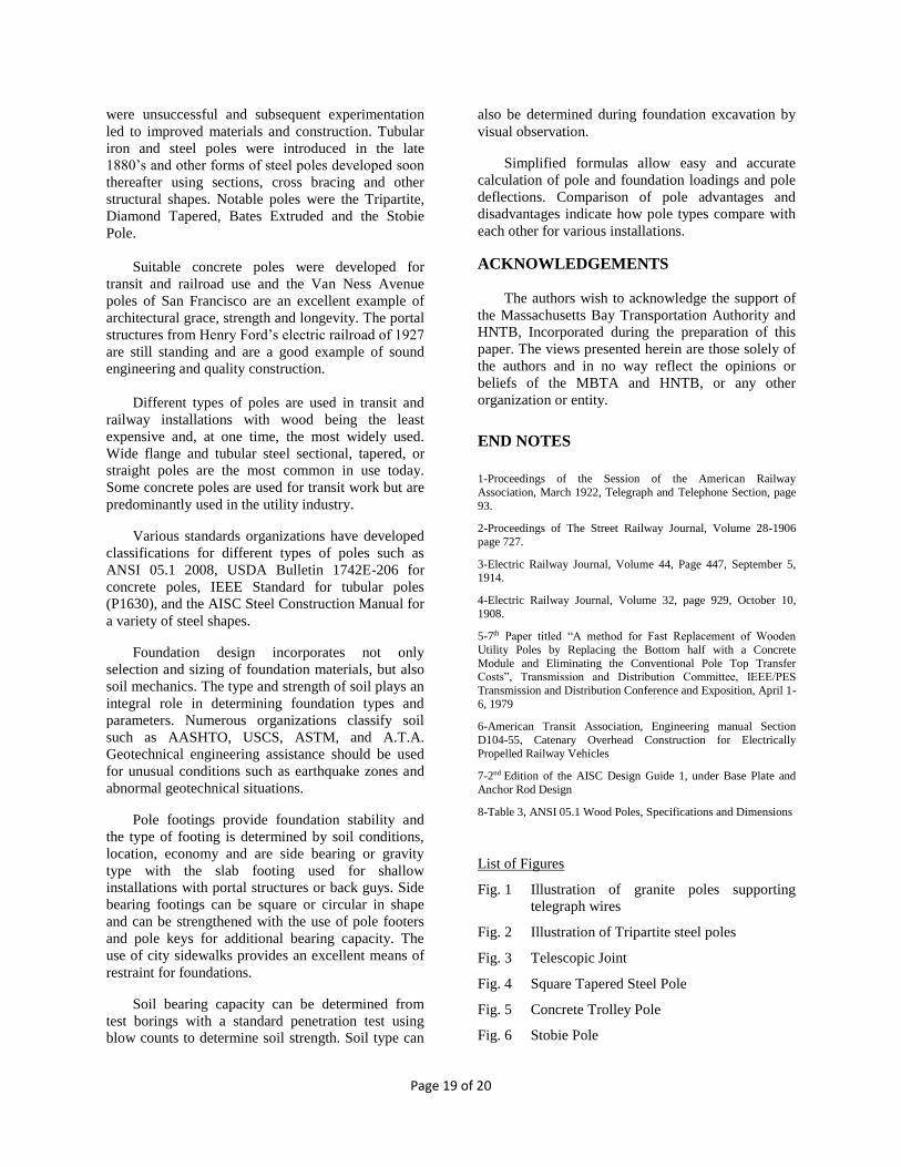
Pole Deflection
Formulas for pole deflection reference Figures
15 and 16. Formulas for the deflection of poles are
given in the following equations:
(f1) One section pole:
𝐷 =𝐿3 x P
3 x E x I
(f2) Two section pole:
𝑌100 = 𝑘𝑋13− 𝑋22
𝐼1+
𝑋23
𝐼2
(f3) Three section pole:
𝑌100 = 𝑘𝑋13 − 𝑋23
𝐼1+
𝑋23 − 𝑋33
𝐼2 +
𝑋33
𝐼3
(f4) Four section pole:
𝑌100 = 𝐾𝑋13 − 𝑋23
𝐼1+
𝑋23 − 𝑋33
𝐼2 +
𝑋33 − 𝑋43
𝐼3+
𝑋43
𝐼4
Refer to Figure 23; K = W100 / 3 E; W100 = 100 lbs
(f5) Tapered pole:
𝐷 =288 𝑥 𝐿3 x H
E [
1
𝐼𝑏 +
1
𝐼𝑚
]
(f6) Wide flange pole:
𝐷 =𝑃 𝐻3
3 E I
(f7) Wood pole:
𝐷 =6.78 𝐿3 𝑃
𝐸 (𝑑𝑔3𝑥 𝑑1)
Note: E = 1.6 x 10⁶ for Southern yellow Pine
E = 2.9 x 10⁶ for Steel
Where:
D = Deflection in inches
L = length of pole at applied load in inches
P = Load applied in pounds
E = modulus of elasticity
I = Moment of inertia
Ib = Moment of Inertia at ground line
Im = Moment of Inertia at middle of pole
H = Height of pole above Ground Line at load
Y = Deflection in inches/100 lbs
dg = Diameter at the ground line
d1 = Diameter where the force is applied
Pole Guys
Formulas for pole guys reference Figures 12 and
13, and are as follows:
(f8) Back Guy:
𝑃2 =𝑃1
Cos θ1
(f9) Side Walk Guy:
𝑃3 = 𝑃2 𝑥 𝐶𝑜𝑠 𝜃2
𝑃4 = 𝑃2 𝑥 𝑆𝑖𝑛 𝜃2
Figure 12
Page 15 of 20
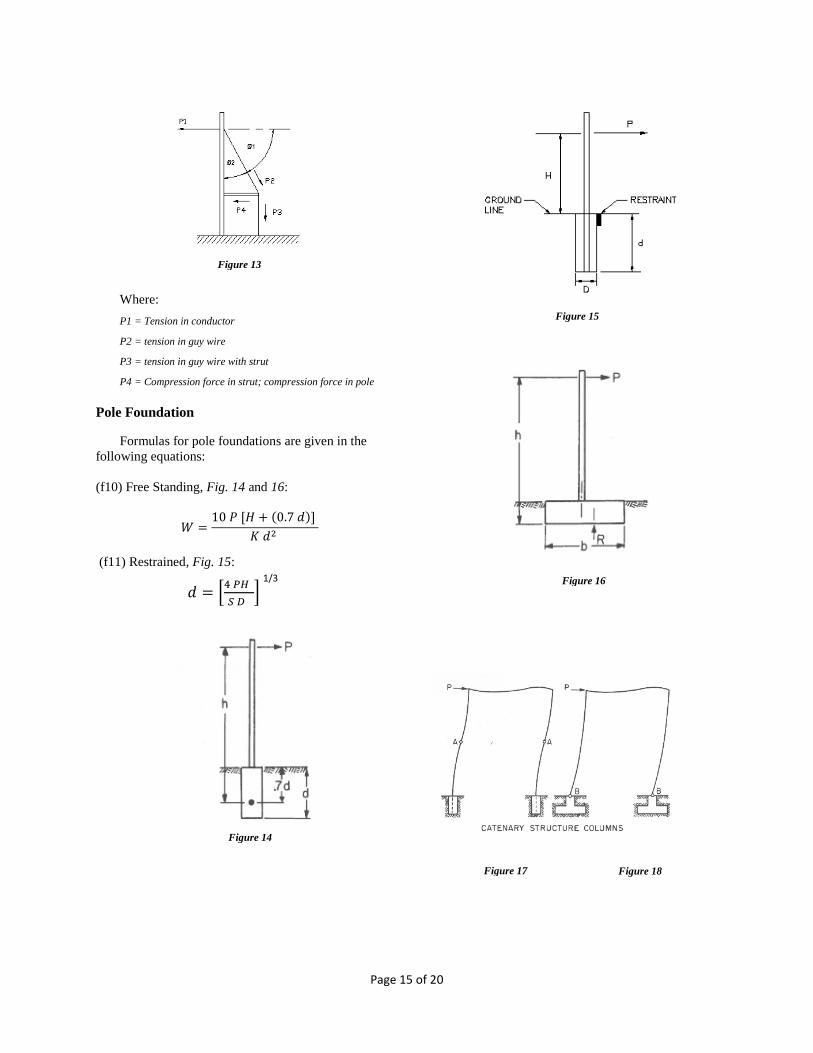
Where:
P1 = Tension in conductor
P2 = tension in guy wire
P3 = tension in guy wire with strut
P4 = Compression force in strut; compression force in pole
Pole Foundation
Formulas for pole foundations are given in the
following equations:
(f10) Free Standing, Fig. 14 and 16:
𝑊 =10 𝑃 [𝐻 + (0.7 𝑑)]
𝐾 𝑑2
(f11) Restrained, Fig. 15:
𝑑 = [4 𝑃𝐻
𝑆 𝐷 ]
Figure 13
Figure 14
Figure 15
1/3 Figure 16
Figure 17 Figure 18
Page 16 of 20
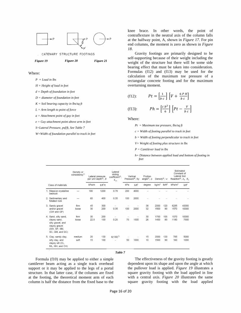
Where:
P = Load in lbs
H = Height of load in feet
d = Depth of foundation in feet
D = diameter of foundation in feet
K = Soil bearing capacity in lbs/sq ft
L = Arm length to point of force
a = Attachment point of guy in feet
e = Guy attachment point above arm in feet
S=Lateral Pressure, psf/ft, See Table 7
W=Width of foundation parallel to track in feet
Formula (f10) may be applied to either a simple
cantilever beam acting as a single track overhead
support or it may be applied to the legs of a portal
structure. In that latter case, if the columns are fixed
at the footing, the theoretical moment arm of each
column is half the distance from the fixed base to the
knee brace. In other words, the point of
contraflexture in the neutral axis of the column falls
at the halfway point, A, shown in Figure 17. For pin
end columns, the moment is zero as shown in Figure
18.
Gravity footings are primarily designed to be
self-supporting because of their weight including the
weight of the structure but there will be some side
bearing effect that must be taken into consideration.
Formulas (f12) and (f13) may be used for the
calculation of the maximum toe pressure of a
rectangular concrete footing and for the maximum
overturning moment.
(f12): 𝑃𝑡 = [1
𝑏 𝑐 ] [𝑉 +
6 𝑃 𝐻
𝑏 𝑐 ]
(f13): 𝑃ℎ = [𝑐 𝑏2
6] [𝑃𝑡 −
𝑉
𝑏 𝑐 ]
Where:
Pt = Maximum toe pressure, lbs/sq ft
c = Width of footing parallel to track in feet
b = Width of footing perpendicular to track in feet
V= Weight of footing plus structure in lbs
P = Cantilever load in lbs
h= Distance between applied load and bottom of footing in
feet
The effectiveness of the gravity footing is greatly
dependent upon its shape and upon the angle at which
the pullover load is applied. Figure 19 illustrates a
square gravity footing with the load applied in line
with a central axis. Figure 20 illustrates the same
square gravity footing with the load applied
Figure 19 Figure 20 Figure 21
Table 7
Page 17 of 20
diagonally while Figure 21 illustrates a circular
footing with the load applied at any point.
The stated formulas apply to Figure 19. Where
the load is applied diagonally, Figure 20, the same
set of formulas may be used, however in calculating
the footing size it must be remembered that the value
of P for use in the formulas is equal to P’ cos 𝝷. For
the round footing, Figure 21, the formulas may be
used for obtaining maximum toe pressure and
maximum overturning moment providing both
formulas are multiplied by 0.66.
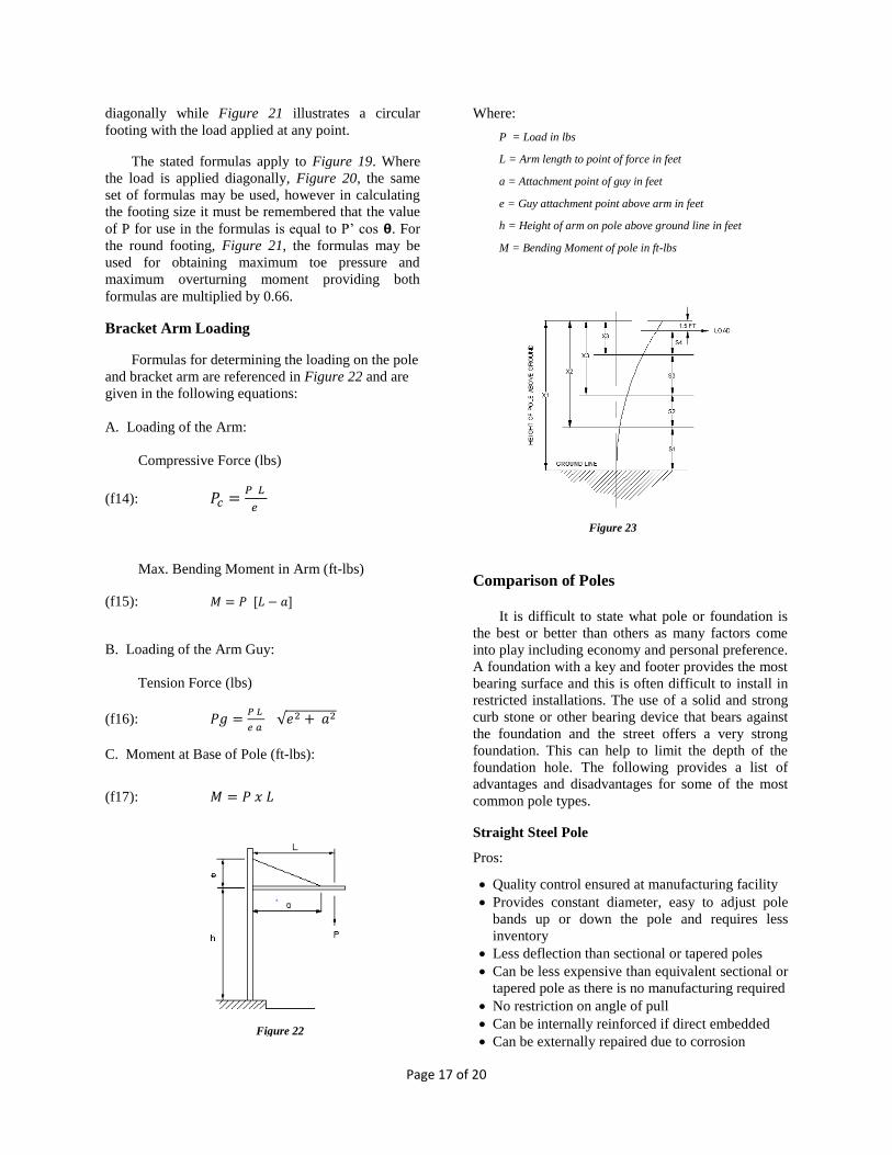
Bracket Arm Loading
Formulas for determining the loading on the pole
and bracket arm are referenced in Figure 22 and are
given in the following equations:
A. Loading of the Arm:
Compressive Force (lbs)
(f14): 𝑃𝑐 =𝑃 𝐿
𝑒
Max. Bending Moment in Arm (ft-lbs)
(f15): 𝑀 = 𝑃 [𝐿 − 𝑎]
B. Loading of the Arm Guy:
Tension Force (lbs)
(f16): 𝑃𝑔 =𝑃 𝐿
𝑒 𝑎 √𝑒2 + 𝑎2
C. Moment at Base of Pole (ft-lbs):
(f17): 𝑀 = 𝑃 𝑥 𝐿
Where:
P = Load in lbs
L = Arm length to point of force in feet
a = Attachment point of guy in feet
e = Guy attachment point above arm in feet
h = Height of arm on pole above ground line in feet
M = Bending Moment of pole in ft-lbs
Comparison of Poles
It is difficult to state what pole or foundation is
the best or better than others as many factors come
into play including economy and personal preference.
A foundation with a key and footer provides the most
bearing surface and this is often difficult to install in
restricted installations. The use of a solid and strong
curb stone or other bearing device that bears against
the foundation and the street offers a very strong
foundation. This can help to limit the depth of the
foundation hole. The following provides a list of
advantages and disadvantages for some of the most
common pole types.
Straight Steel Pole
Pros:
Quality control ensured at manufacturing facility
Provides constant diameter, easy to adjust pole
bands up or down the pole and requires less
inventory
Less deflection than sectional or tapered poles
Can be less expensive than equivalent sectional or
tapered pole as there is no manufacturing required
No restriction on angle of pull
Can be internally reinforced if direct embedded
Can be externally repaired due to corrosion Figure 22
Figure 23

Page 18 of 20
Cons:
Weight per foot not as efficient as sectional or
tapered poles
Less visually appealing due to straightness
Interior of pole is subject to unseen corrosion
Sectional Steel Pole
Pros:
Provides constant diameter in each section
Easy to adjust pole bands up or down the pole
Less weight than constant diameter straight pole
Weight per foot more efficient than straight pipe
No restriction on angle of pull
Can be internally reinforced if direct embedded
Can be externally repaired due to corrosion
Cons:
More expensive than straight pipe or wide flange
section for given section modulus
Interior of pole subject to unseen corrosion
Sections of pipe must be properly secured to
prevent telescoping. Finished joint construction
not visible for inspection and quality control
Section joints can be a source of corrosion
Tapered Steel Pole
Pros:
Less weight than constant diameter straight pole
No restriction on angle of pull
Efficient weight per foot
Less risk of corrosion when compared to sectional
steel poles
Quality control ensured with automated shop
manufacturing process
Can be externally repaired due to corrosion
Cons:
Pole diameter varies along the entire pole length
making adjustment of attachment hardware more
difficult
Will deflect more than straight pole of similar
base diameter and gauge.
Wide Flange Steel Pole
Pros:
Provides high strength per weight per foot in
strong axis direction
Less expensive than straight pipe or tapered poles
for strength
More stiffness thus less deflection
No interior corrosion
Cons:
Strong axis and weak axis limiting direction of
pull
Straight without taper, thus not visually pleasing
unless special adaptations made
Wood Pole
Pros:
Least expensive pole type
No restriction on angle of pull
No grounding requirements as wood is
nonconductive
Ease of installation direct embedded and
backfilled with earth.
Can be externally repaired due to corrosion
Cons:
Risk of decay at ground line from fungi and
insects. Even treated poles lose resistance to
decay over time
Wood poles can warp over time
Limited available strength for high strain loads
compared to steel and concrete poles
Concrete Pole
Pros:
Not susceptible to the same surface corrosion and
decay as steel and wood poles
High compressive strength
High resistance to fire
Ease of installation if direct embedded and
backfilled with earth
Cons:
Spun concrete poles can sink further into earth
under high compressive loads due to open cross-
section
Risks of concrete cracking and spalling
Weak in tension, and rebar can corrode if exposed
to moisture
Heavy and can require heavy machinery to install
CONCLUSION
Poles of varying materials and types have been
used for aerial wire support since the advent of the
telegraph in 1844. Wood was the primary material
initially but variations with concrete were used for
repair, strength or longevity. Early concrete poles
Page 19 of 20
were unsuccessful and subsequent experimentation
led to improved materials and construction. Tubular
iron and steel poles were introduced in the late
1880’s and other forms of steel poles developed soon
thereafter using sections, cross bracing and other
structural shapes. Notable poles were the Tripartite,
Diamond Tapered, Bates Extruded and the Stobie
Pole.
Suitable concrete poles were developed for
transit and railroad use and the Van Ness Avenue
poles of San Francisco are an excellent example of
architectural grace, strength and longevity. The portal
structures from Henry Ford’s electric railroad of 1927
are still standing and are a good example of sound
engineering and quality construction.
Different types of poles are used in transit and
railway installations with wood being the least
expensive and, at one time, the most widely used.
Wide flange and tubular steel sectional, tapered, or
straight poles are the most common in use today.
Some concrete poles are used for transit work but are
predominantly used in the utility industry.
Various standards organizations have developed
classifications for different types of poles such as
ANSI 05.1 2008, USDA Bulletin 1742E-206 for
concrete poles, IEEE Standard for tubular poles
(P1630), and the AISC Steel Construction Manual for
a variety of steel shapes.
Foundation design incorporates not only
selection and sizing of foundation materials, but also
soil mechanics. The type and strength of soil plays an
integral role in determining foundation types and
parameters. Numerous organizations classify soil
such as AASHTO, USCS, ASTM, and A.T.A.
Geotechnical engineering assistance should be used
for unusual conditions such as earthquake zones and
abnormal geotechnical situations.
Pole footings provide foundation stability and
the type of footing is determined by soil conditions,
location, economy and are side bearing or gravity
type with the slab footing used for shallow
installations with portal structures or back guys. Side
bearing footings can be square or circular in shape
and can be strengthened with the use of pole footers
and pole keys for additional bearing capacity. The
use of city sidewalks provides an excellent means of
restraint for foundations.
Soil bearing capacity can be determined from
test borings with a standard penetration test using
blow counts to determine soil strength. Soil type can
also be determined during foundation excavation by
visual observation.
Simplified formulas allow easy and accurate
calculation of pole and foundation loadings and pole
deflections. Comparison of pole advantages and
disadvantages indicate how pole types compare with
each other for various installations.
ACKNOWLEDGEMENTS
The authors wish to acknowledge the support of
the Massachusetts Bay Transportation Authority and
HNTB, Incorporated during the preparation of this
paper. The views presented herein are those solely of
the authors and in no way reflect the opinions or
beliefs of the MBTA and HNTB, or any other
organization or entity.
END NOTES
1-Proceedings of the Session of the American Railway
Association, March 1922, Telegraph and Telephone Section, page
93.
2-Proceedings of The Street Railway Journal, Volume 28-1906
page 727.
3-Electric Railway Journal, Volume 44, Page 447, September 5, 1914.
4-Electric Railway Journal, Volume 32, page 929, October 10,
1908.
5-7th Paper titled “A method for Fast Replacement of Wooden
Utility Poles by Replacing the Bottom half with a Concrete
Module and Eliminating the Conventional Pole Top Transfer Costs”, Transmission and Distribution Committee, IEEE/PES
Transmission and Distribution Conference and Exposition, April 1-
6, 1979
6-American Transit Association, Engineering manual Section
D104-55, Catenary Overhead Construction for Electrically
Propelled Railway Vehicles
7-2nd Edition of the AISC Design Guide 1, under Base Plate and
Anchor Rod Design
8-Table 3, ANSI 05.1 Wood Poles, Specifications and Dimensions
List of Figures
Fig. 1 Illustration of granite poles supporting
telegraph wires
Fig. 2 Illustration of Tripartite steel poles
Fig. 3 Telescopic Joint
Fig. 4 Square Tapered Steel Pole
Fig. 5 Concrete Trolley Pole
Fig. 6 Stobie Pole

Page 20 of 20
Fig. 7 Van Ness Avenue Concrete Poles
Fig. 8 Concrete Catenary Supporting Structure
Fig. 9 Steel Shape Anchor Base Foundation
Fig. 10 Anchor Base Plate Grouting Effects
Fig. 11 George Washington Bridge Streetlights
Fig. 12 Back Guy
Fig. 13 Sidewalk Guy
Fig. 14 Cantilever Pole Foundation
Fig. 15 Restrained Pole Foundation
Fig. 16 Gravity Footing Cantilever Pole
Fig. 17 Fixed Portal Structure
Fig. 18 Pinned Portal Structure
Fig. 19 Rectangular Foundation with Straight Pull
Fig. 20 Rectangular Foundation with Angled Pull
Fig. 21 Circular Foundation
Fig. 22 Bracket Arm
Fig. 23 Deflection for Sectional Pole
List of Tables
Table 1 Standard for Iron/Steel Poles
Table 2 Classification of Wood Poles
Table 3 Classification of Concrete Poles
Table 4 Cost Comparison Between Poles
Table 5 A.T.A. Soil Criteria
Table 6 Pole Cost Comparison
Table 7 Soil Properties for Post Foundation Design