Embed Size (px)
Citation preview
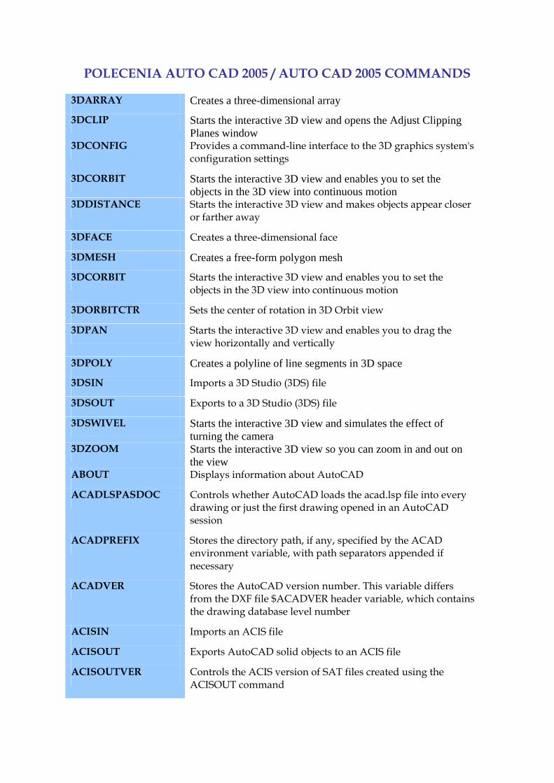
POLECENIA AUTO CAD 2005 / AUTO CAD 2005 COMMANDS 3DARRAY Creates a three-dimensional array
3DCLIP Starts the interactive 3D view and opens the Adjust Clipping Planes window
3DCONFIG Provides a command-line interface to the 3D graphics system's configuration settings
3DCORBIT Starts the interactive 3D view and enables you to set the objects in the 3D view into continuous motion
3DDISTANCE Starts the interactive 3D view and makes objects appear closer or farther away
3DFACE Creates a three-dimensional face
3DMESH Creates a free-form polygon mesh
3DCORBIT Starts the interactive 3D view and enables you to set the objects in the 3D view into continuous motion
3DORBITCTR Sets the center of rotation in 3D Orbit view
3DPAN Starts the interactive 3D view and enables you to drag the view horizontally and vertically
3DPOLY Creates a polyline of line segments in 3D space
3DSIN Imports a 3D Studio (3DS) file
3DSOUT Exports to a 3D Studio (3DS) file
3DSWIVEL Starts the interactive 3D view and simulates the effect of turning the camera
3DZOOM Starts the interactive 3D view so you can zoom in and out on the view
ABOUT Displays information about AutoCAD
ACADLSPASDOC Controls whether AutoCAD loads the acad.lsp file into every drawing or just the first drawing opened in an AutoCAD session
ACADPREFIX Stores the directory path, if any, specified by the ACAD environment variable, with path separators appended if necessary
ACADVER Stores the AutoCAD version number. This variable differs from the DXF file $ACADVER header variable, which contains the drawing database level number
ACISIN Imports an ACIS file
ACISOUT Exports AutoCAD solid objects to an ACIS file
ACISOUTVER Controls the ACIS version of SAT files created using the ACISOUT command
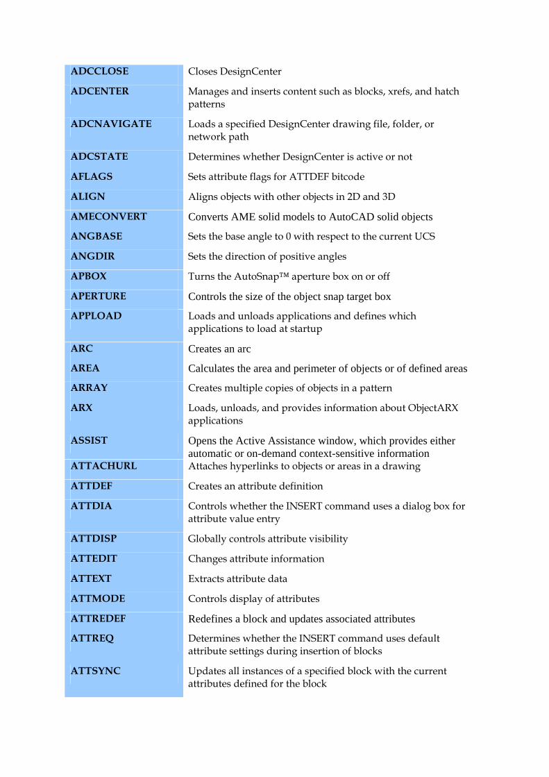
ADCCLOSE Closes DesignCenter
ADCENTER Manages and inserts content such as blocks, xrefs, and hatch patterns
ADCNAVIGATE Loads a specified DesignCenter drawing file, folder, or network path
ADCSTATE Determines whether DesignCenter is active or not
AFLAGS Sets attribute flags for ATTDEF bitcode
ALIGN Aligns objects with other objects in 2D and 3D
AMECONVERT Converts AME solid models to AutoCAD solid objects
ANGBASE Sets the base angle to 0 with respect to the current UCS
ANGDIR Sets the direction of positive angles
APBOX Turns the AutoSnap™ aperture box on or off
APERTURE Controls the size of the object snap target box
APPLOAD Loads and unloads applications and defines which applications to load at startup
ARC Creates an arc
AREA Calculates the area and perimeter of objects or of defined areas
ARRAY Creates multiple copies of objects in a pattern
ARX Loads, unloads, and provides information about ObjectARX applications
ASSIST Opens the Active Assistance window, which provides either automatic or on-demand context-sensitive information
ATTACHURL Attaches hyperlinks to objects or areas in a drawing
ATTDEF Creates an attribute definition
ATTDIA Controls whether the INSERT command uses a dialog box for attribute value entry
ATTDISP Globally controls attribute visibility
ATTEDIT Changes attribute information
ATTEXT Extracts attribute data
ATTMODE Controls display of attributes
ATTREDEF Redefines a block and updates associated attributes
ATTREQ Determines whether the INSERT command uses default attribute settings during insertion of blocks
ATTSYNC Updates all instances of a specified block with the current attributes defined for the block

AUDIT Evaluates the integrity of a drawing
AUNITS Sets units for angles
AUTOSNAP Controls AutoSnap marker, tooltip, and magnet
BACKGROUND Sets up the background for your scene
BACKZ Stores the back clipping plane offset from the target plane for the current viewport, in drawing units
BASE Sets the insertion base point for the current drawing
BATTMAN Edits attribute properties of a block definition
BHATCH Fills an enclosed area or selected objects with a hatch pattern or gradient fill
BINDTYPE Controls how xref names are handled when binding xrefs or editing xrefs in place
BLIPMODE Controls the display of marker blips
BLOCK Creates a block definition from objects you select
BLOCKICON Generates preview images for blocks displayed in DesignCenter
BMPOUT Saves selected objects to a file in device-independent bitmap format
BOUNDARY Creates a region or a polyline from an enclosed area
BOX Creates a three-dimensional solid box
BREAK Breaks the selected object between two points
BROWSER Launches the default web browser defined in your system's registry
CAL Evaluates mathematical and geometric expressions
CAMERA Sets a different camera and target location
CCONFIG The CCONFIG command has been discontinued
CDATE Sets calendar date and time
CECOLOR Sets the color of new objects
CELTSCALE Sets the current object linetype scaling factor
CELTYPE Sets the linetype of new objects
CELWEIGHT Sets the lineweight of new objects
CHAMFER Bevels the edges of objects
CHAMFERA Sets the first chamfer distance
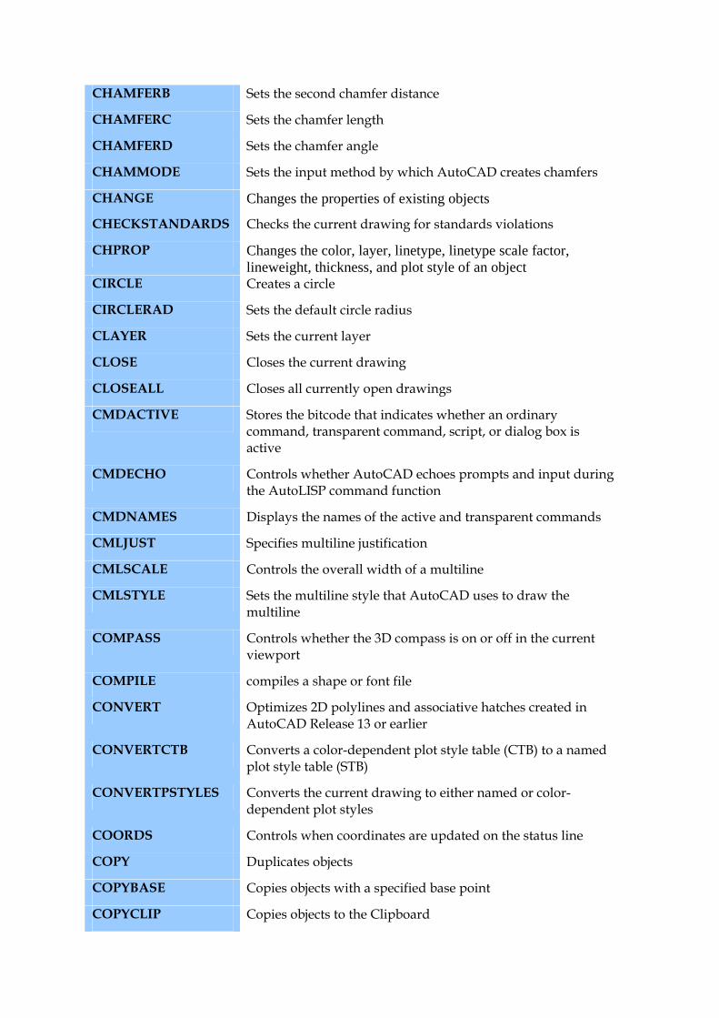
CHAMFERB Sets the second chamfer distance
CHAMFERC Sets the chamfer length
CHAMFERD Sets the chamfer angle
CHAMMODE Sets the input method by which AutoCAD creates chamfers
CHANGE Changes the properties of existing objects
CHECKSTANDARDS Checks the current drawing for standards violations
CHPROP Changes the color, layer, linetype, linetype scale factor, lineweight, thickness, and plot style of an object
CIRCLE Creates a circle
CIRCLERAD Sets the default circle radius
CLAYER Sets the current layer
CLOSE Closes the current drawing
CLOSEALL Closes all currently open drawings
CMDACTIVE Stores the bitcode that indicates whether an ordinary command, transparent command, script, or dialog box is active
CMDECHO Controls whether AutoCAD echoes prompts and input during the AutoLISP command function
CMDNAMES Displays the names of the active and transparent commands
CMLJUST Specifies multiline justification
CMLSCALE Controls the overall width of a multiline
CMLSTYLE Sets the multiline style that AutoCAD uses to draw the multiline
COMPASS Controls whether the 3D compass is on or off in the current viewport
COMPILE compiles a shape or font file
CONVERT Optimizes 2D polylines and associative hatches created in AutoCAD Release 13 or earlier
CONVERTCTB Converts a color-dependent plot style table (CTB) to a named plot style table (STB)
CONVERTPSTYLES Converts the current drawing to either named or color-dependent plot styles
COORDS Controls when coordinates are updated on the status line
COPY Duplicates objects
COPYBASE Copies objects with a specified base point
COPYCLIP Copies objects to the Clipboard
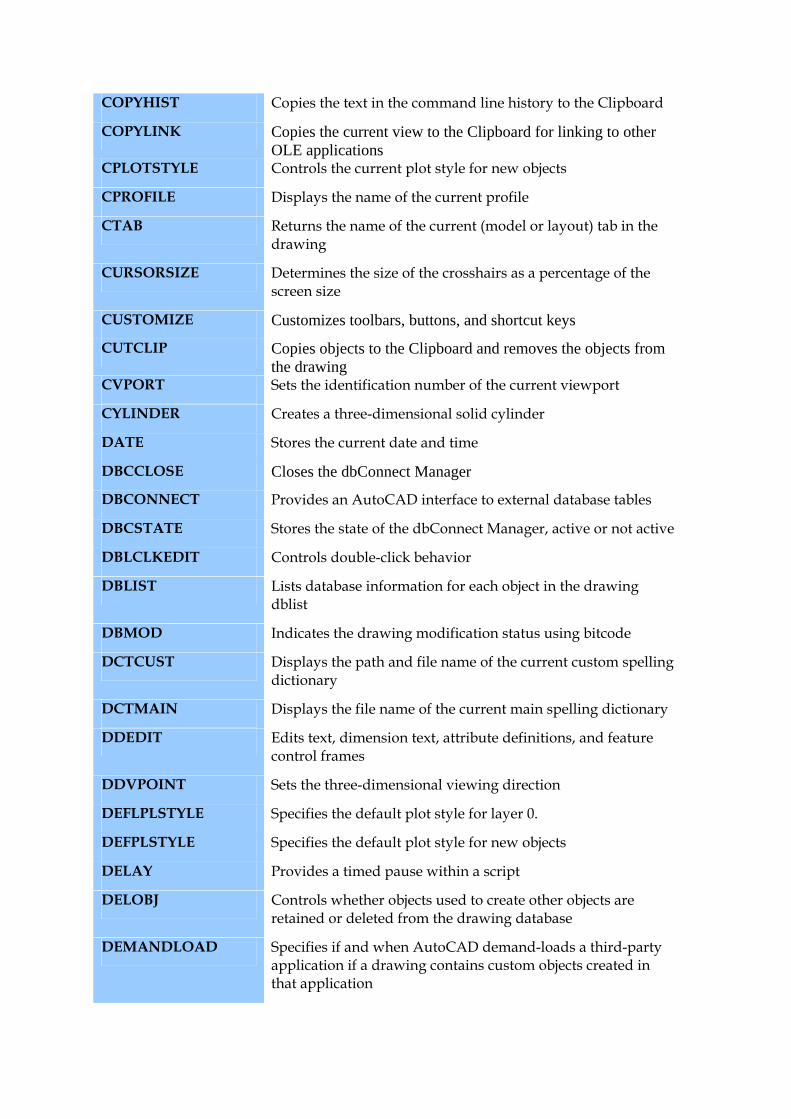
COPYHIST Copies the text in the command line history to the Clipboard
COPYLINK Copies the current view to the Clipboard for linking to other OLE applications
CPLOTSTYLE Controls the current plot style for new objects
CPROFILE Displays the name of the current profile
CTAB Returns the name of the current (model or layout) tab in the drawing
CURSORSIZE Determines the size of the crosshairs as a percentage of the screen size
CUSTOMIZE Customizes toolbars, buttons, and shortcut keys
CUTCLIP Copies objects to the Clipboard and removes the objects from the drawing
CVPORT Sets the identification number of the current viewport
CYLINDER Creates a three-dimensional solid cylinder
DATE Stores the current date and time
DBCCLOSE Closes the dbConnect Manager
DBCONNECT Provides an AutoCAD interface to external database tables
DBCSTATE Stores the state of the dbConnect Manager, active or not active
DBLCLKEDIT Controls double-click behavior
DBLIST Lists database information for each object in the drawing dblist
DBMOD Indicates the drawing modification status using bitcode
DCTCUST Displays the path and file name of the current custom spelling dictionary
DCTMAIN Displays the file name of the current main spelling dictionary
DDEDIT Edits text, dimension text, attribute definitions, and feature control frames
DDVPOINT Sets the three-dimensional viewing direction
DEFLPLSTYLE Specifies the default plot style for layer 0.
DEFPLSTYLE Specifies the default plot style for new objects
DELAY Provides a timed pause within a script
DELOBJ Controls whether objects used to create other objects are retained or deleted from the drawing database
DEMANDLOAD Specifies if and when AutoCAD demand-loads a third-party application if a drawing contains custom objects created in that application
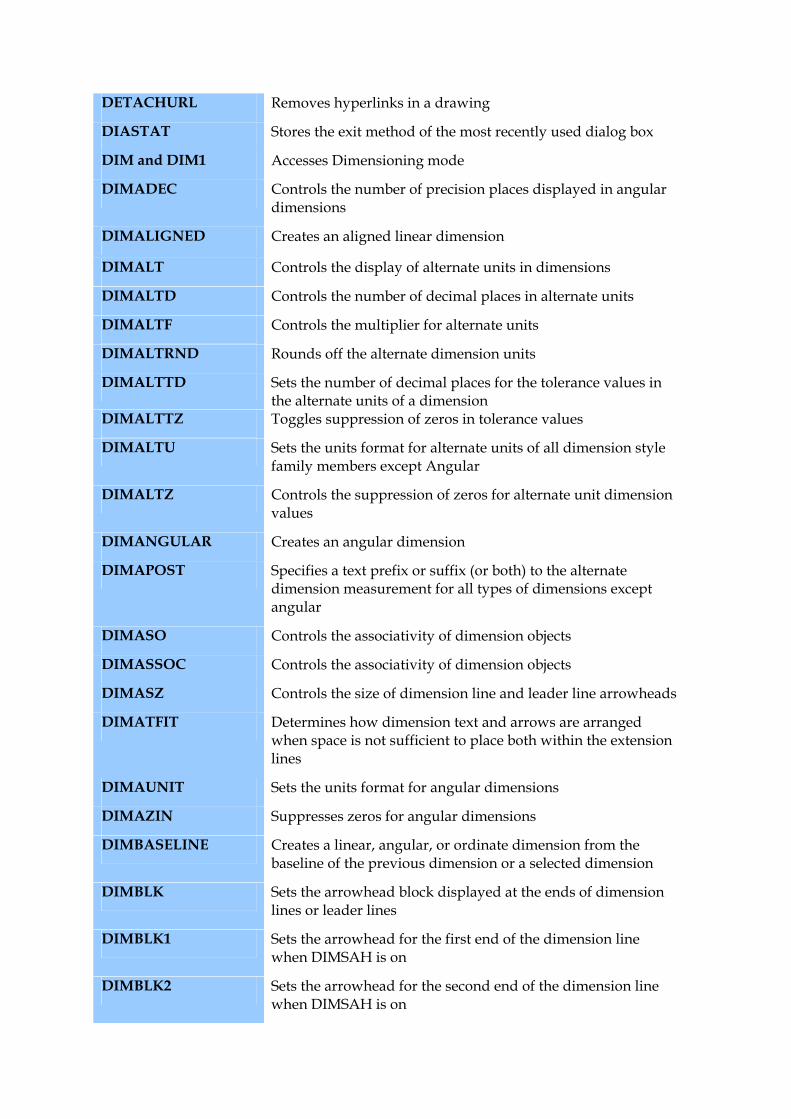
DETACHURL Removes hyperlinks in a drawing
DIASTAT Stores the exit method of the most recently used dialog box
DIM and DIM1 Accesses Dimensioning mode
DIMADEC Controls the number of precision places displayed in angular dimensions
DIMALIGNED Creates an aligned linear dimension
DIMALT Controls the display of alternate units in dimensions
DIMALTD Controls the number of decimal places in alternate units
DIMALTF Controls the multiplier for alternate units
DIMALTRND Rounds off the alternate dimension units
DIMALTTD Sets the number of decimal places for the tolerance values in the alternate units of a dimension
DIMALTTZ Toggles suppression of zeros in tolerance values
DIMALTU Sets the units format for alternate units of all dimension style family members except Angular
DIMALTZ Controls the suppression of zeros for alternate unit dimension values
DIMANGULAR Creates an angular dimension
DIMAPOST Specifies a text prefix or suffix (or both) to the alternate dimension measurement for all types of dimensions except angular
DIMASO Controls the associativity of dimension objects
DIMASSOC Controls the associativity of dimension objects
DIMASZ Controls the size of dimension line and leader line arrowheads
DIMATFIT Determines how dimension text and arrows are arranged when space is not sufficient to place both within the extension lines
DIMAUNIT Sets the units format for angular dimensions
DIMAZIN Suppresses zeros for angular dimensions
DIMBASELINE Creates a linear, angular, or ordinate dimension from the baseline of the previous dimension or a selected dimension
DIMBLK Sets the arrowhead block displayed at the ends of dimension lines or leader lines
DIMBLK1 Sets the arrowhead for the first end of the dimension line when DIMSAH is on
DIMBLK2 Sets the arrowhead for the second end of the dimension line when DIMSAH is on
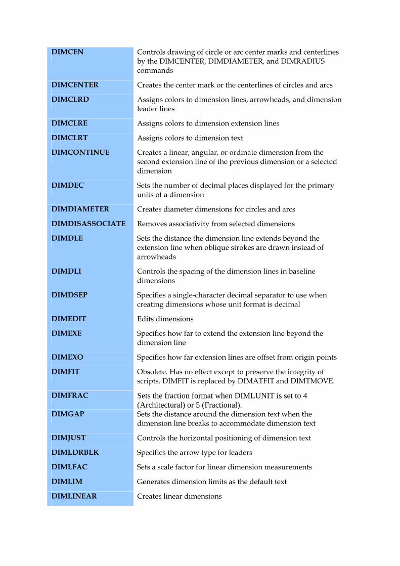
DIMCEN Controls drawing of circle or arc center marks and centerlines by the DIMCENTER, DIMDIAMETER, and DIMRADIUS commands
DIMCENTER Creates the center mark or the centerlines of circles and arcs
DIMCLRD Assigns colors to dimension lines, arrowheads, and dimension leader lines
DIMCLRE Assigns colors to dimension extension lines
DIMCLRT Assigns colors to dimension text
DIMCONTINUE Creates a linear, angular, or ordinate dimension from the second extension line of the previous dimension or a selected dimension
DIMDEC Sets the number of decimal places displayed for the primary units of a dimension
DIMDIAMETER Creates diameter dimensions for circles and arcs
DIMDISASSOCIATE Removes associativity from selected dimensions
DIMDLE Sets the distance the dimension line extends beyond the extension line when oblique strokes are drawn instead of arrowheads
DIMDLI Controls the spacing of the dimension lines in baseline dimensions
DIMDSEP Specifies a single-character decimal separator to use when creating dimensions whose unit format is decimal
DIMEDIT Edits dimensions
DIMEXE Specifies how far to extend the extension line beyond the dimension line
DIMEXO Specifies how far extension lines are offset from origin points
DIMFIT Obsolete. Has no effect except to preserve the integrity of scripts. DIMFIT is replaced by DIMATFIT and DIMTMOVE.
DIMFRAC Sets the fraction format when DIMLUNIT is set to 4 (Architectural) or 5 (Fractional).
DIMGAP Sets the distance around the dimension text when the dimension line breaks to accommodate dimension text
DIMJUST Controls the horizontal positioning of dimension text
DIMLDRBLK Specifies the arrow type for leaders
DIMLFAC Sets a scale factor for linear dimension measurements
DIMLIM Generates dimension limits as the default text
DIMLINEAR Creates linear dimensions
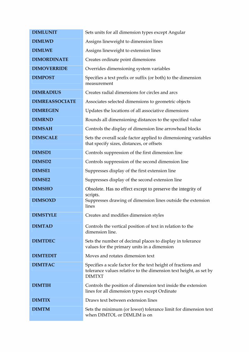
DIMLUNIT Sets units for all dimension types except Angular
DIMLWD Assigns lineweight to dimension lines
DIMLWE Assigns lineweight to extension lines
DIMORDINATE Creates ordinate point dimensions
DIMOVERRIDE Overrides dimensioning system variables
DIMPOST Specifies a text prefix or suffix (or both) to the dimension measurement
DIMRADIUS Creates radial dimensions for circles and arcs
DIMREASSOCIATE Associates selected dimensions to geometric objects
DIMREGEN Updates the locations of all associative dimensions
DIMRND Rounds all dimensioning distances to the specified value
DIMSAH Controls the display of dimension line arrowhead blocks
DIMSCALE Sets the overall scale factor applied to dimensioning variables that specify sizes, distances, or offsets
DIMSD1 Controls suppression of the first dimension line
DIMSD2 Controls suppression of the second dimension line
DIMSE1 Suppresses display of the first extension line
DIMSE2 Suppresses display of the second extension line
DIMSHO Obsolete. Has no effect except to preserve the integrity of scripts.
DIMSOXD Suppresses drawing of dimension lines outside the extension lines
DIMSTYLE Creates and modifies dimension styles
DIMTAD Controls the vertical position of text in relation to the dimension line.
DIMTDEC Sets the number of decimal places to display in tolerance values for the primary units in a dimension
DIMTEDIT Moves and rotates dimension text
DIMTFAC Specifies a scale factor for the text height of fractions and tolerance values relative to the dimension text height, as set by DIMTXT
DIMTIH Controls the position of dimension text inside the extension lines for all dimension types except Ordinate
DIMTIX Draws text between extension lines
DIMTM Sets the minimum (or lower) tolerance limit for dimension text when DIMTOL or DIMLIM is on
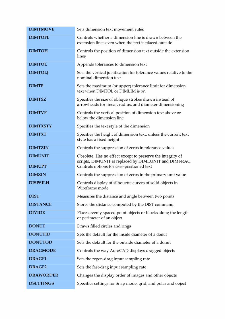
DIMTMOVE Sets dimension text movement rules
DIMTOFL Controls whether a dimension line is drawn between the extension lines even when the text is placed outside
DIMTOH Controls the position of dimension text outside the extension lines
DIMTOL Appends tolerances to dimension text
DIMTOLJ Sets the vertical justification for tolerance values relative to the nominal dimension text
DIMTP Sets the maximum (or upper) tolerance limit for dimension text when DIMTOL or DIMLIM is on
DIMTSZ Specifies the size of oblique strokes drawn instead of arrowheads for linear, radius, and diameter dimensioning
DIMTVP Controls the vertical position of dimension text above or below the dimension line
DIMTXSTY Specifies the text style of the dimension
DIMTXT Specifies the height of dimension text, unless the current text style has a fixed height
DIMTZIN Controls the suppression of zeros in tolerance values
DIMUNIT Obsolete. Has no effect except to preserve the integrity of scripts. DIMUNIT is replaced by DIMLUNIT and DIMFRAC.
DIMUPT Controls options for user-positioned text
DIMZIN Controls the suppression of zeros in the primary unit value
DISPSILH Controls display of silhouette curves of solid objects in Wireframe mode
DIST Measures the distance and angle between two points
DISTANCE Stores the distance computed by the DIST command
DIVIDE Places evenly spaced point objects or blocks along the length or perimeter of an object
DONUT Draws filled circles and rings
DONUTID Sets the default for the inside diameter of a donut
DONUTOD Sets the default for the outside diameter of a donut
DRAGMODE Controls the way AutoCAD displays dragged objects
DRAGP1 Sets the regen-drag input sampling rate
DRAGP2 Sets the fast-drag input sampling rate
DRAWORDER Changes the display order of images and other objects
DSETTINGS Specifies settings for Snap mode, grid, and polar and object
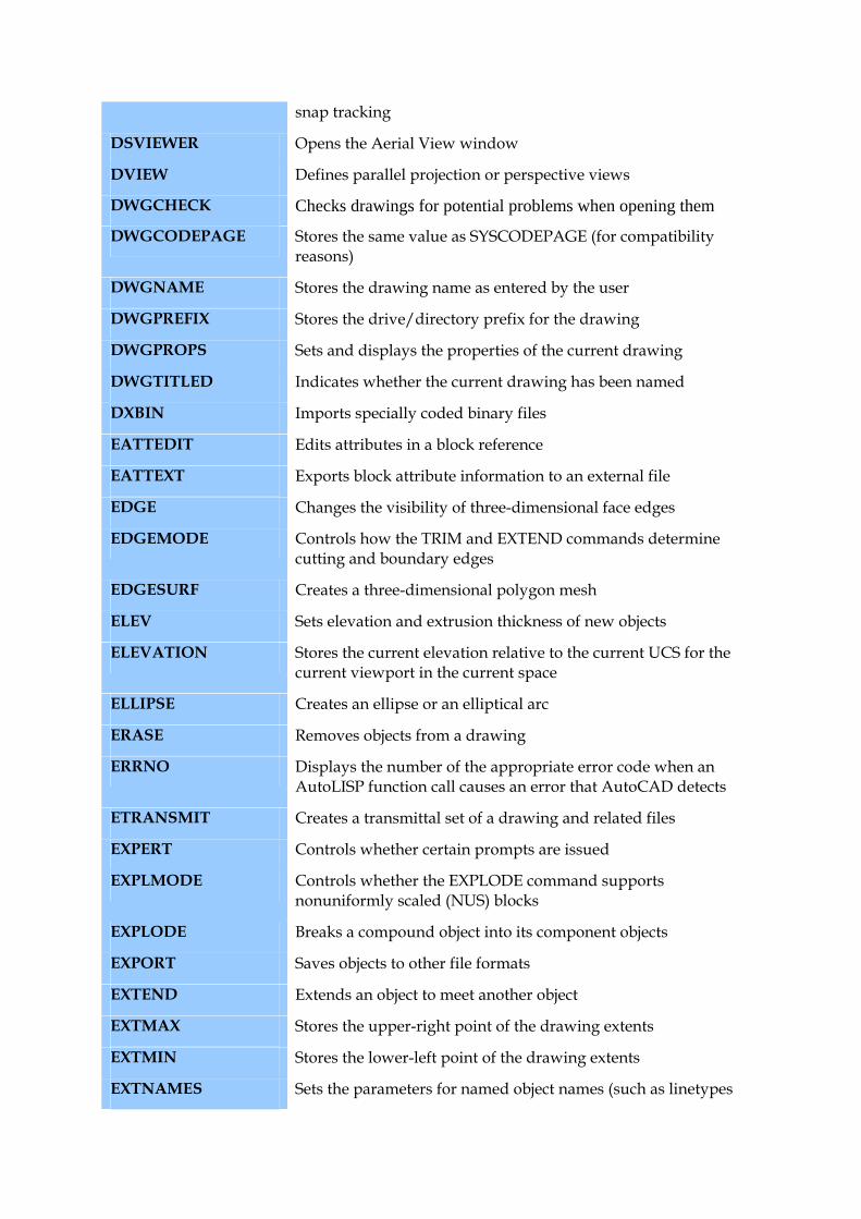
snap tracking
DSVIEWER Opens the Aerial View window
DVIEW Defines parallel projection or perspective views
DWGCHECK Checks drawings for potential problems when opening them
DWGCODEPAGE Stores the same value as SYSCODEPAGE (for compatibility reasons)
DWGNAME Stores the drawing name as entered by the user
DWGPREFIX Stores the drive/directory prefix for the drawing
DWGPROPS Sets and displays the properties of the current drawing
DWGTITLED Indicates whether the current drawing has been named
DXBIN Imports specially coded binary files
EATTEDIT Edits attributes in a block reference
EATTEXT Exports block attribute information to an external file
EDGE Changes the visibility of three-dimensional face edges
EDGEMODE Controls how the TRIM and EXTEND commands determine cutting and boundary edges
EDGESURF Creates a three-dimensional polygon mesh
ELEV Sets elevation and extrusion thickness of new objects
ELEVATION Stores the current elevation relative to the current UCS for the current viewport in the current space
ELLIPSE Creates an ellipse or an elliptical arc
ERASE Removes objects from a drawing
ERRNO Displays the number of the appropriate error code when an AutoLISP function call causes an error that AutoCAD detects
ETRANSMIT Creates a transmittal set of a drawing and related files
EXPERT Controls whether certain prompts are issued
EXPLMODE Controls whether the EXPLODE command supports nonuniformly scaled (NUS) blocks
EXPLODE Breaks a compound object into its component objects
EXPORT Saves objects to other file formats
EXTEND Extends an object to meet another object
EXTMAX Stores the upper-right point of the drawing extents
EXTMIN Stores the lower-left point of the drawing extents
EXTNAMES Sets the parameters for named object names (such as linetypes
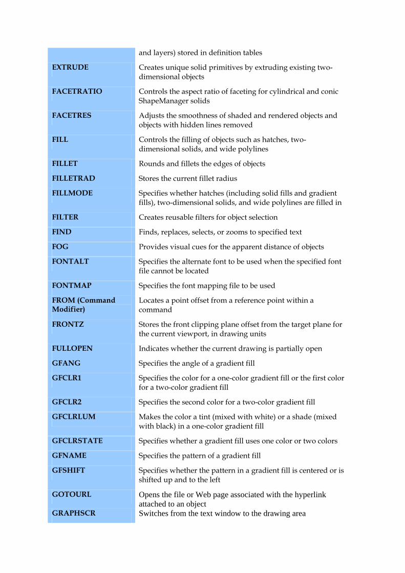
and layers) stored in definition tables
EXTRUDE Creates unique solid primitives by extruding existing two-dimensional objects
FACETRATIO Controls the aspect ratio of faceting for cylindrical and conic ShapeManager solids
FACETRES Adjusts the smoothness of shaded and rendered objects and objects with hidden lines removed
FILL Controls the filling of objects such as hatches, two-dimensional solids, and wide polylines
FILLET Rounds and fillets the edges of objects
FILLETRAD Stores the current fillet radius
FILLMODE Specifies whether hatches (including solid fills and gradient fills), two-dimensional solids, and wide polylines are filled in
FILTER Creates reusable filters for object selection
FIND Finds, replaces, selects, or zooms to specified text
FOG Provides visual cues for the apparent distance of objects
FONTALT Specifies the alternate font to be used when the specified font file cannot be located
FONTMAP Specifies the font mapping file to be used
FROM (Command Modifier)
Locates a point offset from a reference point within a command
FRONTZ Stores the front clipping plane offset from the target plane for the current viewport, in drawing units
FULLOPEN Indicates whether the current drawing is partially open
GFANG Specifies the angle of a gradient fill
GFCLR1 Specifies the color for a one-color gradient fill or the first color for a two-color gradient fill
GFCLR2 Specifies the second color for a two-color gradient fill
GFCLRLUM Makes the color a tint (mixed with white) or a shade (mixed with black) in a one-color gradient fill
GFCLRSTATE Specifies whether a gradient fill uses one color or two colors
GFNAME Specifies the pattern of a gradient fill
GFSHIFT Specifies whether the pattern in a gradient fill is centered or is shifted up and to the left
GOTOURL Opens the file or Web page associated with the hyperlink attached to an object
GRAPHSCR Switches from the text window to the drawing area
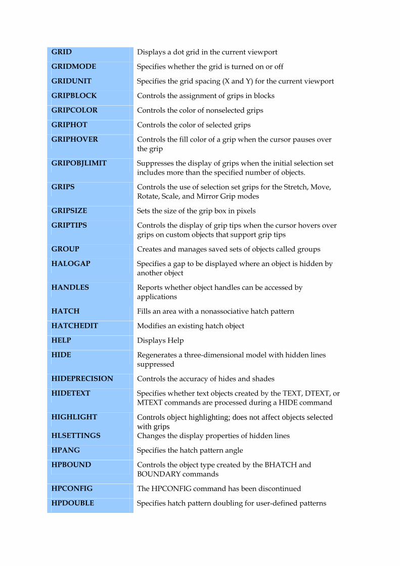
GRID Displays a dot grid in the current viewport
GRIDMODE Specifies whether the grid is turned on or off
GRIDUNIT Specifies the grid spacing (X and Y) for the current viewport
GRIPBLOCK Controls the assignment of grips in blocks
GRIPCOLOR Controls the color of nonselected grips
GRIPHOT Controls the color of selected grips
GRIPHOVER Controls the fill color of a grip when the cursor pauses over the grip
GRIPOBJLIMIT Suppresses the display of grips when the initial selection set includes more than the specified number of objects.
GRIPS Controls the use of selection set grips for the Stretch, Move, Rotate, Scale, and Mirror Grip modes
GRIPSIZE Sets the size of the grip box in pixels
GRIPTIPS Controls the display of grip tips when the cursor hovers over grips on custom objects that support grip tips
GROUP Creates and manages saved sets of objects called groups
HALOGAP Specifies a gap to be displayed where an object is hidden by another object
HANDLES Reports whether object handles can be accessed by applications
HATCH Fills an area with a nonassociative hatch pattern
HATCHEDIT Modifies an existing hatch object
HELP Displays Help
HIDE Regenerates a three-dimensional model with hidden lines suppressed
HIDEPRECISION Controls the accuracy of hides and shades
HIDETEXT Specifies whether text objects created by the TEXT, DTEXT, or MTEXT commands are processed during a HIDE command
HIGHLIGHT Controls object highlighting; does not affect objects selected with grips
HLSETTINGS Changes the display properties of hidden lines
HPANG Specifies the hatch pattern angle
HPBOUND Controls the object type created by the BHATCH and BOUNDARY commands
HPCONFIG The HPCONFIG command has been discontinued
HPDOUBLE Specifies hatch pattern doubling for user-defined patterns
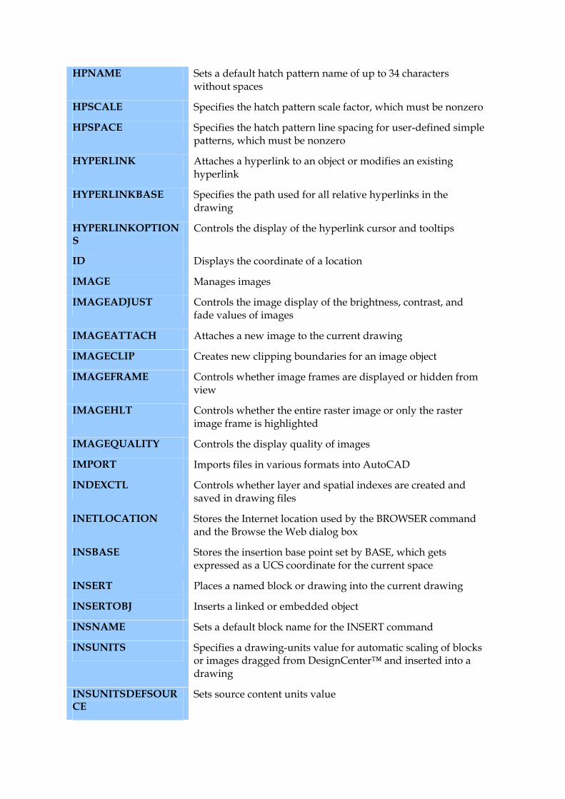
HPNAME Sets a default hatch pattern name of up to 34 characters without spaces
HPSCALE Specifies the hatch pattern scale factor, which must be nonzero
HPSPACE Specifies the hatch pattern line spacing for user-defined simple patterns, which must be nonzero
HYPERLINK Attaches a hyperlink to an object or modifies an existing hyperlink
HYPERLINKBASE Specifies the path used for all relative hyperlinks in the drawing
HYPERLINKOPTIONS
Controls the display of the hyperlink cursor and tooltips
ID Displays the coordinate of a location
IMAGE Manages images
IMAGEADJUST Controls the image display of the brightness, contrast, and fade values of images
IMAGEATTACH Attaches a new image to the current drawing
IMAGECLIP Creates new clipping boundaries for an image object
IMAGEFRAME Controls whether image frames are displayed or hidden from view
IMAGEHLT Controls whether the entire raster image or only the raster image frame is highlighted
IMAGEQUALITY Controls the display quality of images
IMPORT Imports files in various formats into AutoCAD
INDEXCTL Controls whether layer and spatial indexes are created and saved in drawing files
INETLOCATION Stores the Internet location used by the BROWSER command and the Browse the Web dialog box
INSBASE Stores the insertion base point set by BASE, which gets expressed as a UCS coordinate for the current space
INSERT Places a named block or drawing into the current drawing
INSERTOBJ Inserts a linked or embedded object
INSNAME Sets a default block name for the INSERT command
INSUNITS Specifies a drawing-units value for automatic scaling of blocks or images dragged from DesignCenter™ and inserted into a drawing
INSUNITSDEFSOURCE
Sets source content units value
INSUNITSDEFTARGET
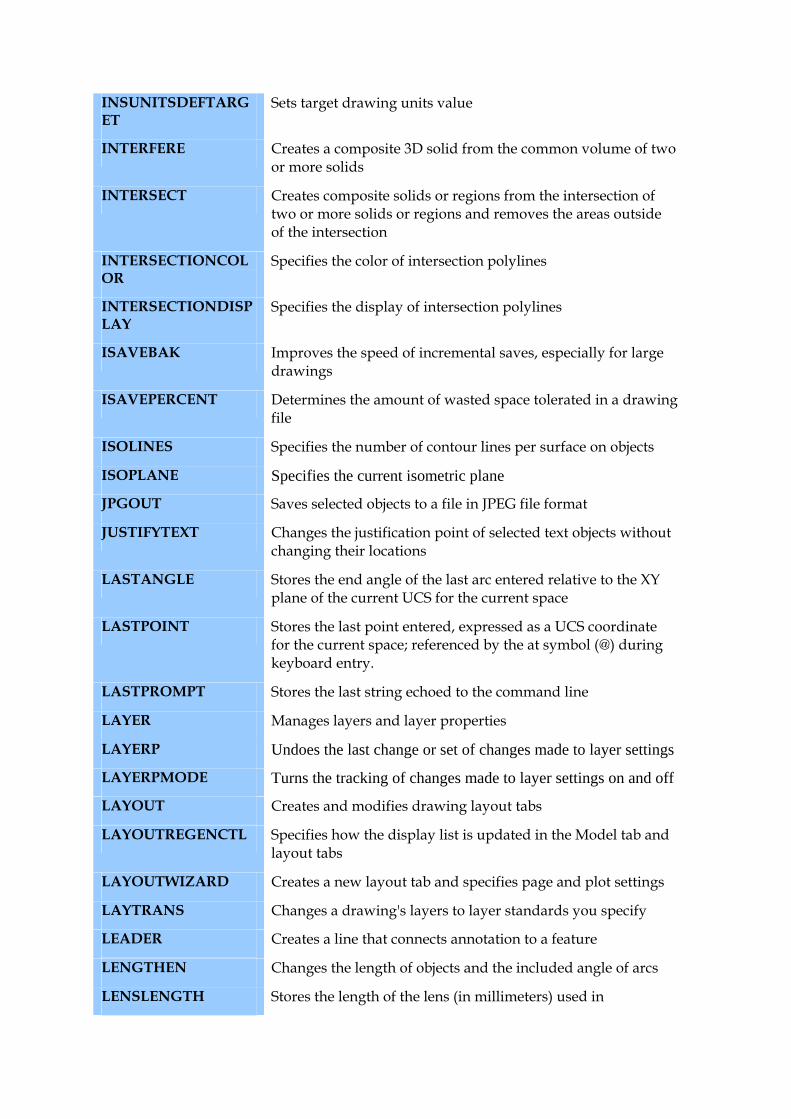
Sets target drawing units value
INTERFERE Creates a composite 3D solid from the common volume of two or more solids
INTERSECT Creates composite solids or regions from the intersection of two or more solids or regions and removes the areas outside of the intersection
INTERSECTIONCOLOR
Specifies the color of intersection polylines
INTERSECTIONDISPLAY
Specifies the display of intersection polylines
ISAVEBAK Improves the speed of incremental saves, especially for large drawings
ISAVEPERCENT Determines the amount of wasted space tolerated in a drawing file
ISOLINES Specifies the number of contour lines per surface on objects
ISOPLANE Specifies the current isometric plane
JPGOUT Saves selected objects to a file in JPEG file format
JUSTIFYTEXT Changes the justification point of selected text objects without changing their locations
LASTANGLE Stores the end angle of the last arc entered relative to the XY plane of the current UCS for the current space
LASTPOINT Stores the last point entered, expressed as a UCS coordinate for the current space; referenced by the at symbol (@) during keyboard entry.
LASTPROMPT Stores the last string echoed to the command line
LAYER Manages layers and layer properties
LAYERP Undoes the last change or set of changes made to layer settings
LAYERPMODE Turns the tracking of changes made to layer settings on and off
LAYOUT Creates and modifies drawing layout tabs
LAYOUTREGENCTL Specifies how the display list is updated in the Model tab and layout tabs
LAYOUTWIZARD Creates a new layout tab and specifies page and plot settings
LAYTRANS Changes a drawing's layers to layer standards you specify
LEADER Creates a line that connects annotation to a feature
LENGTHEN Changes the length of objects and the included angle of arcs
LENSLENGTH Stores the length of the lens (in millimeters) used in
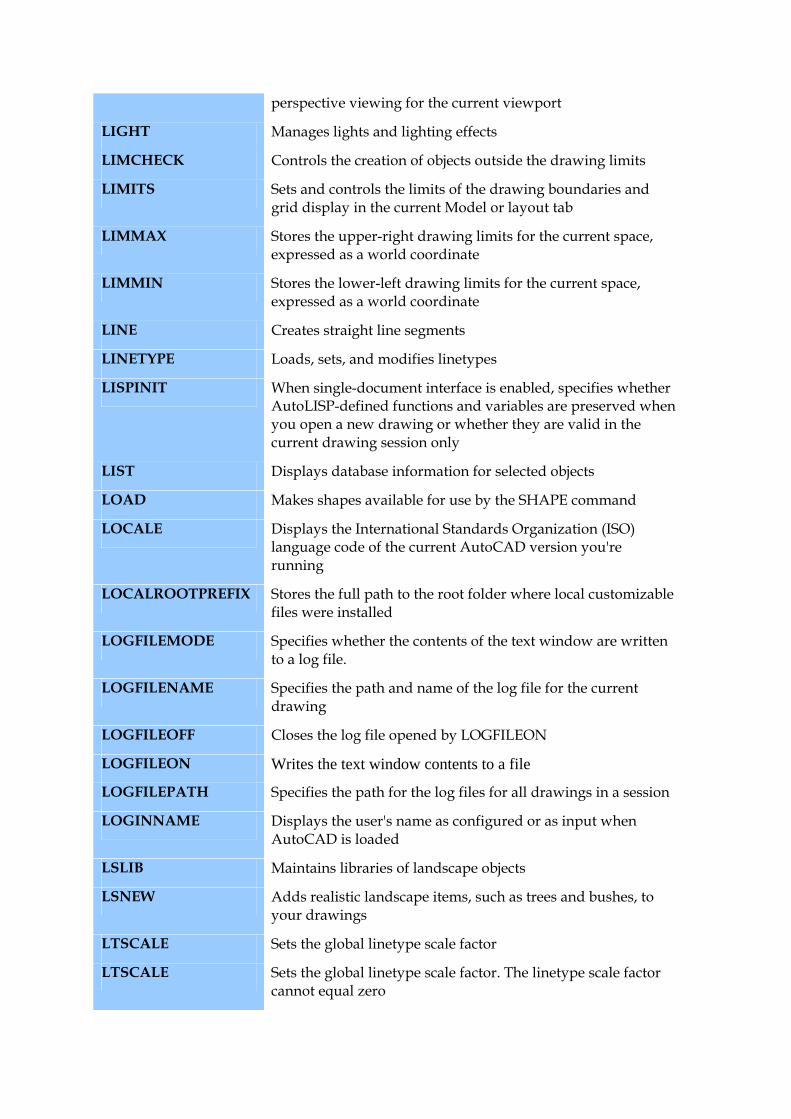
perspective viewing for the current viewport
LIGHT Manages lights and lighting effects
LIMCHECK Controls the creation of objects outside the drawing limits
LIMITS Sets and controls the limits of the drawing boundaries and grid display in the current Model or layout tab
LIMMAX Stores the upper-right drawing limits for the current space, expressed as a world coordinate
LIMMIN Stores the lower-left drawing limits for the current space, expressed as a world coordinate
LINE Creates straight line segments
LINETYPE Loads, sets, and modifies linetypes
LISPINIT When single-document interface is enabled, specifies whether AutoLISP-defined functions and variables are preserved when you open a new drawing or whether they are valid in the current drawing session only
LIST Displays database information for selected objects
LOAD Makes shapes available for use by the SHAPE command
LOCALE Displays the International Standards Organization (ISO) language code of the current AutoCAD version you're running
LOCALROOTPREFIX Stores the full path to the root folder where local customizable files were installed
LOGFILEMODE Specifies whether the contents of the text window are written to a log file.
LOGFILENAME Specifies the path and name of the log file for the current drawing
LOGFILEOFF Closes the log file opened by LOGFILEON
LOGFILEON Writes the text window contents to a file
LOGFILEPATH Specifies the path for the log files for all drawings in a session
LOGINNAME Displays the user's name as configured or as input when AutoCAD is loaded
LSLIB Maintains libraries of landscape objects
LSNEW Adds realistic landscape items, such as trees and bushes, to your drawings
LTSCALE Sets the global linetype scale factor
LTSCALE Sets the global linetype scale factor. The linetype scale factor cannot equal zero
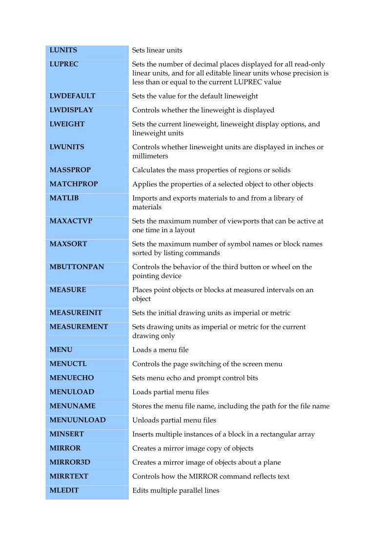
LUNITS Sets linear units
LUPREC Sets the number of decimal places displayed for all read-only linear units, and for all editable linear units whose precision is less than or equal to the current LUPREC value
LWDEFAULT Sets the value for the default lineweight
LWDISPLAY Controls whether the lineweight is displayed
LWEIGHT Sets the current lineweight, lineweight display options, and lineweight units
LWUNITS Controls whether lineweight units are displayed in inches or millimeters
MASSPROP Calculates the mass properties of regions or solids
MATCHPROP Applies the properties of a selected object to other objects
MATLIB Imports and exports materials to and from a library of materials
MAXACTVP Sets the maximum number of viewports that can be active at one time in a layout
MAXSORT Sets the maximum number of symbol names or block names sorted by listing commands
MBUTTONPAN Controls the behavior of the third button or wheel on the pointing device
MEASURE Places point objects or blocks at measured intervals on an object
MEASUREINIT Sets the initial drawing units as imperial or metric
MEASUREMENT Sets drawing units as imperial or metric for the current drawing only
MENU Loads a menu file
MENUCTL Controls the page switching of the screen menu
MENUECHO Sets menu echo and prompt control bits
MENULOAD Loads partial menu files
MENUNAME Stores the menu file name, including the path for the file name
MENUUNLOAD Unloads partial menu files
MINSERT Inserts multiple instances of a block in a rectangular array
MIRROR Creates a mirror image copy of objects
MIRROR3D Creates a mirror image of objects about a plane
MIRRTEXT Controls how the MIRROR command reflects text
MLEDIT Edits multiple parallel lines
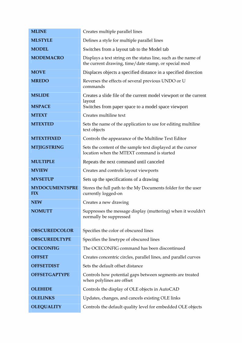
MLINE Creates multiple parallel lines
MLSTYLE Defines a style for multiple parallel lines
MODEL Switches from a layout tab to the Model tab
MODEMACRO Displays a text string on the status line, such as the name of the current drawing, time/date stamp, or special mod
MOVE Displaces objects a specified distance in a specified direction
MREDO Reverses the effects of several previous UNDO or U commands
MSLIDE Creates a slide file of the current model viewport or the current layout
MSPACE Switches from paper space to a model space viewport
MTEXT Creates multiline text
MTEXTED Sets the name of the application to use for editing multiline text objects
MTEXTFIXED Controls the appearance of the Multiline Text Editor
MTJIGSTRING Sets the content of the sample text displayed at the cursor location when the MTEXT command is started
MULTIPLE Repeats the next command until canceled
MVIEW Creates and controls layout viewports
MVSETUP Sets up the specifications of a drawing
MYDOCUMENTSPREFIX
Stores the full path to the My Documents folder for the user currently logged-on
NEW Creates a new drawing
NOMUTT Suppresses the message display (muttering) when it wouldn't normally be suppressed
OBSCUREDCOLOR Specifies the color of obscured lines
OBSCUREDLTYPE Specifies the linetype of obscured lines
OCECONFIG The OCECONFIG command has been discontinued
OFFSET Creates concentric circles, parallel lines, and parallel curves
OFFSETDIST Sets the default offset distance
OFFSETGAPTYPE Controls how potential gaps between segments are treated when polylines are offset
OLEHIDE Controls the display of OLE objects in AutoCAD
OLELINKS Updates, changes, and cancels existing OLE links
OLEQUALITY Controls the default quality level for embedded OLE objects
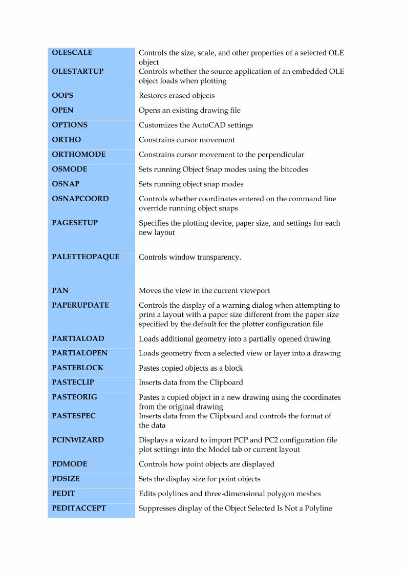
OLESCALE Controls the size, scale, and other properties of a selected OLE object
OLESTARTUP Controls whether the source application of an embedded OLE object loads when plotting
OOPS Restores erased objects
OPEN Opens an existing drawing file
OPTIONS Customizes the AutoCAD settings
ORTHO Constrains cursor movement
ORTHOMODE Constrains cursor movement to the perpendicular
OSMODE Sets running Object Snap modes using the bitcodes
OSNAP Sets running object snap modes
OSNAPCOORD Controls whether coordinates entered on the command line override running object snaps
PAGESETUP Specifies the plotting device, paper size, and settings for each new layout
PALETTEOPAQUE Controls window transparency.
PAN Moves the view in the current viewport
PAPERUPDATE Controls the display of a warning dialog when attempting to print a layout with a paper size different from the paper size specified by the default for the plotter configuration file
PARTIALOAD Loads additional geometry into a partially opened drawing
PARTIALOPEN Loads geometry from a selected view or layer into a drawing
PASTEBLOCK Pastes copied objects as a block
PASTECLIP Inserts data from the Clipboard
PASTEORIG Pastes a copied object in a new drawing using the coordinates from the original drawing
PASTESPEC Inserts data from the Clipboard and controls the format of the data
PCINWIZARD Displays a wizard to import PCP and PC2 configuration file plot settings into the Model tab or current layout
PDMODE Controls how point objects are displayed
PDSIZE Sets the display size for point objects
PEDIT Edits polylines and three-dimensional polygon meshes
PEDITACCEPT Suppresses display of the Object Selected Is Not a Polyline
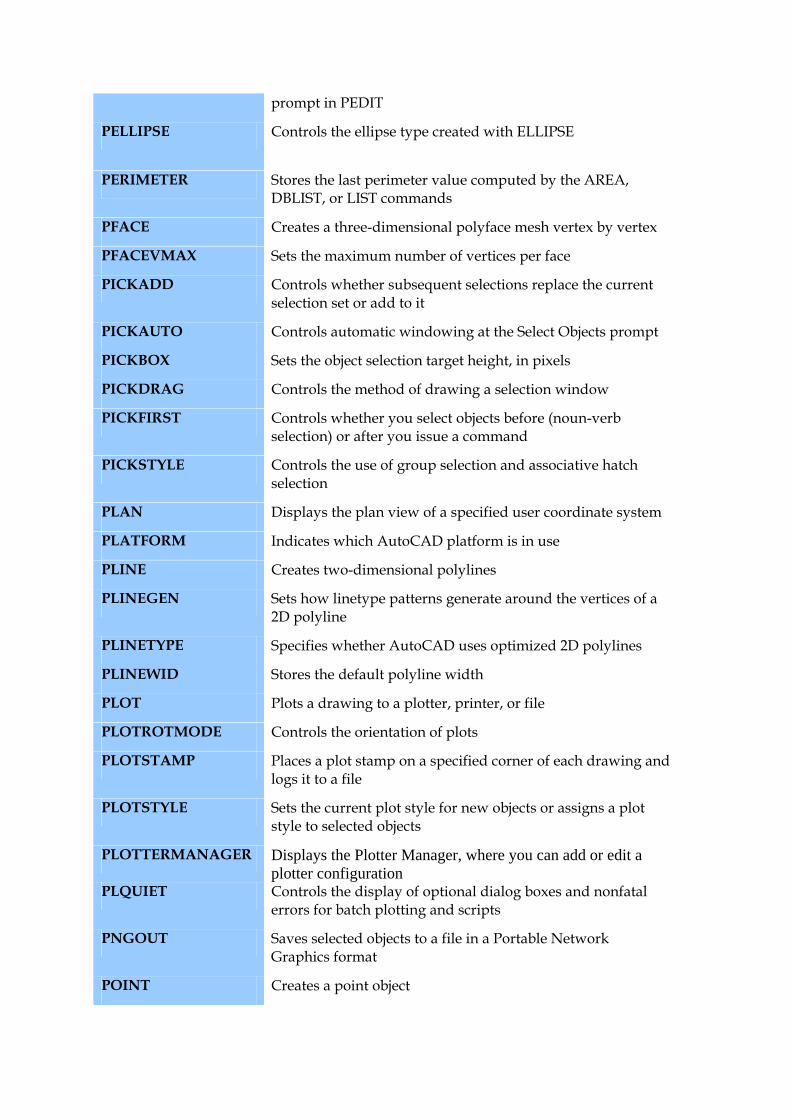
prompt in PEDIT
PELLIPSE Controls the ellipse type created with ELLIPSE
PERIMETER Stores the last perimeter value computed by the AREA, DBLIST, or LIST commands
PFACE Creates a three-dimensional polyface mesh vertex by vertex
PFACEVMAX Sets the maximum number of vertices per face
PICKADD Controls whether subsequent selections replace the current selection set or add to it
PICKAUTO Controls automatic windowing at the Select Objects prompt
PICKBOX Sets the object selection target height, in pixels
PICKDRAG Controls the method of drawing a selection window
PICKFIRST Controls whether you select objects before (noun-verb selection) or after you issue a command
PICKSTYLE Controls the use of group selection and associative hatch selection
PLAN Displays the plan view of a specified user coordinate system
PLATFORM Indicates which AutoCAD platform is in use
PLINE Creates two-dimensional polylines
PLINEGEN Sets how linetype patterns generate around the vertices of a 2D polyline
PLINETYPE Specifies whether AutoCAD uses optimized 2D polylines
PLINEWID Stores the default polyline width
PLOT Plots a drawing to a plotter, printer, or file
PLOTROTMODE Controls the orientation of plots
PLOTSTAMP Places a plot stamp on a specified corner of each drawing and logs it to a file
PLOTSTYLE Sets the current plot style for new objects or assigns a plot style to selected objects
PLOTTERMANAGER Displays the Plotter Manager, where you can add or edit a plotter configuration
PLQUIET Controls the display of optional dialog boxes and nonfatal errors for batch plotting and scripts
PNGOUT Saves selected objects to a file in a Portable Network Graphics format
POINT Creates a point object
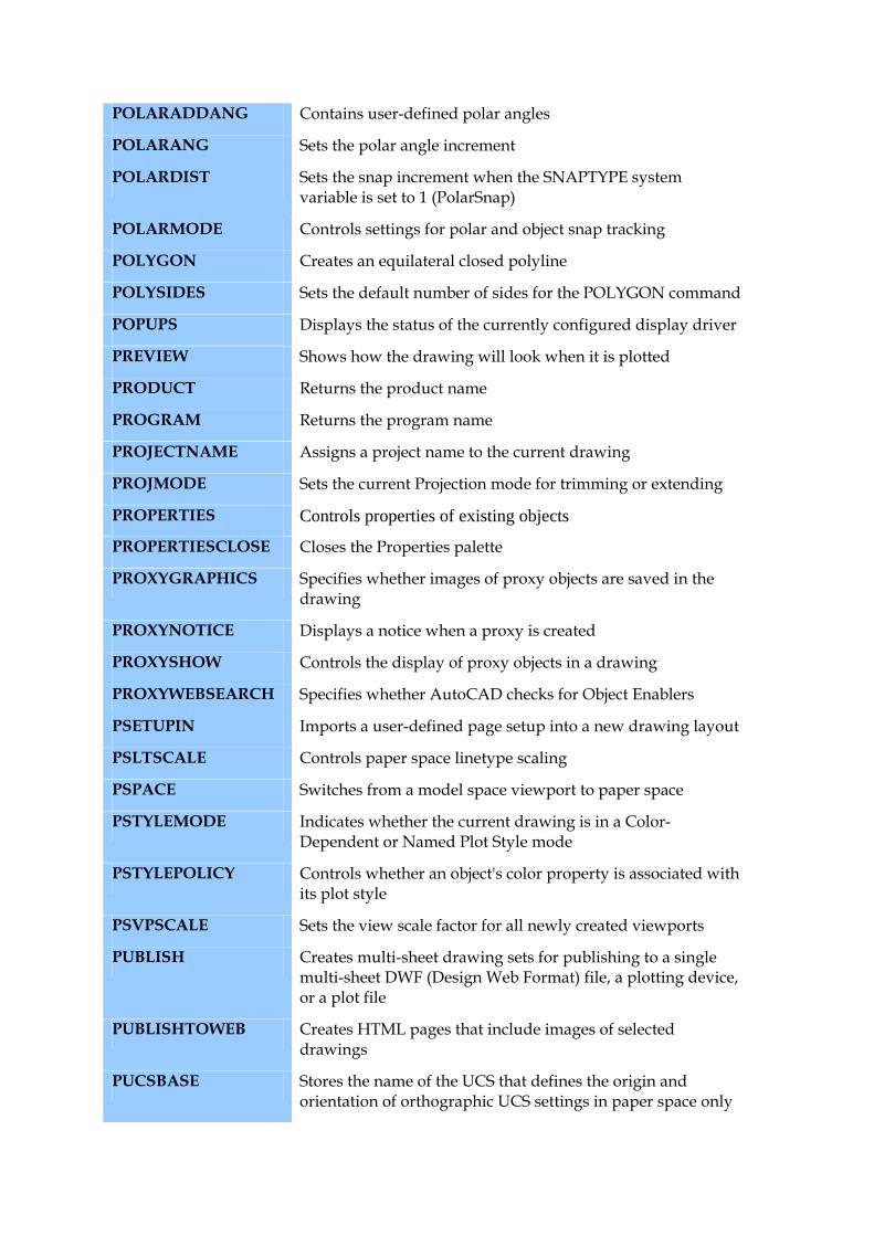
POLARADDANG Contains user-defined polar angles
POLARANG Sets the polar angle increment
POLARDIST Sets the snap increment when the SNAPTYPE system variable is set to 1 (PolarSnap)
POLARMODE Controls settings for polar and object snap tracking
POLYGON Creates an equilateral closed polyline
POLYSIDES Sets the default number of sides for the POLYGON command
POPUPS Displays the status of the currently configured display driver
PREVIEW Shows how the drawing will look when it is plotted
PRODUCT Returns the product name
PROGRAM Returns the program name
PROJECTNAME Assigns a project name to the current drawing
PROJMODE Sets the current Projection mode for trimming or extending
PROPERTIES Controls properties of existing objects
PROPERTIESCLOSE Closes the Properties palette
PROXYGRAPHICS Specifies whether images of proxy objects are saved in the drawing
PROXYNOTICE Displays a notice when a proxy is created
PROXYSHOW Controls the display of proxy objects in a drawing
PROXYWEBSEARCH Specifies whether AutoCAD checks for Object Enablers
PSETUPIN Imports a user-defined page setup into a new drawing layout
PSLTSCALE Controls paper space linetype scaling
PSPACE Switches from a model space viewport to paper space
PSTYLEMODE Indicates whether the current drawing is in a Color-Dependent or Named Plot Style mode
PSTYLEPOLICY Controls whether an object's color property is associated with its plot style
PSVPSCALE Sets the view scale factor for all newly created viewports
PUBLISH Creates multi-sheet drawing sets for publishing to a single multi-sheet DWF (Design Web Format) file, a plotting device, or a plot file
PUBLISHTOWEB Creates HTML pages that include images of selected drawings
PUCSBASE Stores the name of the UCS that defines the origin and orientation of orthographic UCS settings in paper space only
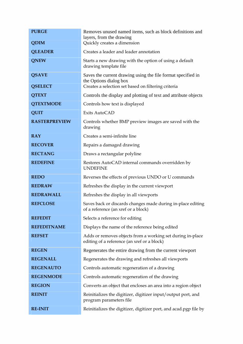
PURGE Removes unused named items, such as block definitions and layers, from the drawing
QDIM Quickly creates a dimension
QLEADER Creates a leader and leader annotation
QNEW Starts a new drawing with the option of using a default drawing template file
QSAVE Saves the current drawing using the file format specified in the Options dialog box
QSELECT Creates a selection set based on filtering criteria
QTEXT Controls the display and plotting of text and attribute objects
QTEXTMODE Controls how text is displayed
QUIT Exits AutoCAD
RASTERPREVIEW Controls whether BMP preview images are saved with the drawing
RAY Creates a semi-infinite line
RECOVER Repairs a damaged drawing
RECTANG Draws a rectangular polyline
REDEFINE Restores AutoCAD internal commands overridden by UNDEFINE
REDO Reverses the effects of previous UNDO or U commands
REDRAW Refreshes the display in the current viewport
REDRAWALL Refreshes the display in all viewports
REFCLOSE Saves back or discards changes made during in-place editing of a reference (an xref or a block)
REFEDIT Selects a reference for editing
REFEDITNAME Displays the name of the reference being edited
REFSET Adds or removes objects from a working set during in-place editing of a reference (an xref or a block)
REGEN Regenerates the entire drawing from the current viewport
REGENALL Regenerates the drawing and refreshes all viewports
REGENAUTO Controls automatic regeneration of a drawing
REGENMODE Controls automatic regeneration of the drawing
REGION Converts an object that encloses an area into a region object
REINIT Reinitializes the digitizer, digitizer input/output port, and program parameters file
RE-INIT Reinitializes the digitizer, digitizer port, and acad.pgp file by
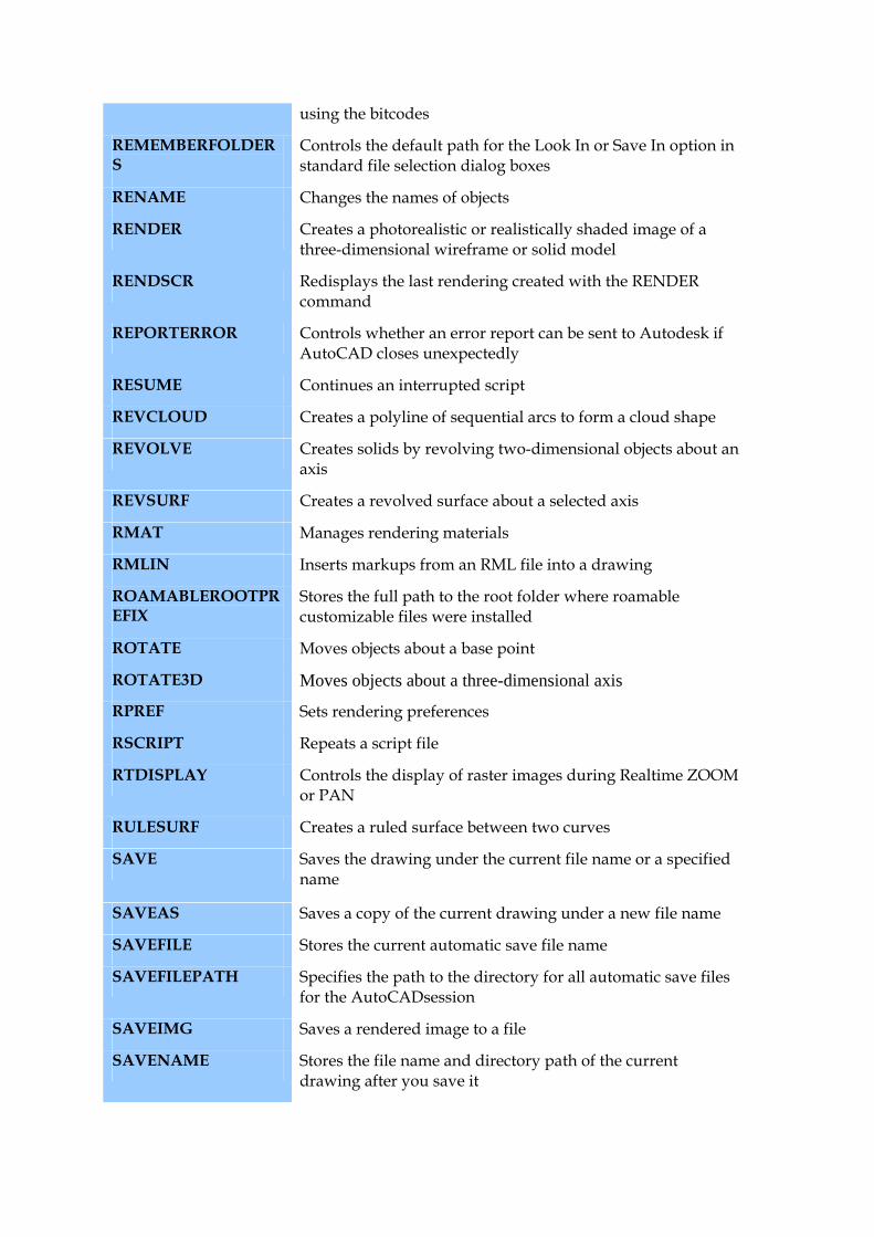
using the bitcodes
REMEMBERFOLDERS
Controls the default path for the Look In or Save In option in standard file selection dialog boxes
RENAME Changes the names of objects
RENDER Creates a photorealistic or realistically shaded image of a three-dimensional wireframe or solid model
RENDSCR Redisplays the last rendering created with the RENDER command
REPORTERROR Controls whether an error report can be sent to Autodesk if AutoCAD closes unexpectedly
RESUME Continues an interrupted script
REVCLOUD Creates a polyline of sequential arcs to form a cloud shape
REVOLVE Creates solids by revolving two-dimensional objects about an axis
REVSURF Creates a revolved surface about a selected axis
RMAT Manages rendering materials
RMLIN Inserts markups from an RML file into a drawing
ROAMABLEROOTPREFIX
Stores the full path to the root folder where roamable customizable files were installed
ROTATE Moves objects about a base point
ROTATE3D Moves objects about a three-dimensional axis
RPREF Sets rendering preferences
RSCRIPT Repeats a script file
RTDISPLAY Controls the display of raster images during Realtime ZOOM or PAN
RULESURF Creates a ruled surface between two curves
SAVE Saves the drawing under the current file name or a specified name
SAVEAS Saves a copy of the current drawing under a new file name
SAVEFILE Stores the current automatic save file name
SAVEFILEPATH Specifies the path to the directory for all automatic save files for the AutoCADsession
SAVEIMG Saves a rendered image to a file
SAVENAME Stores the file name and directory path of the current drawing after you save it
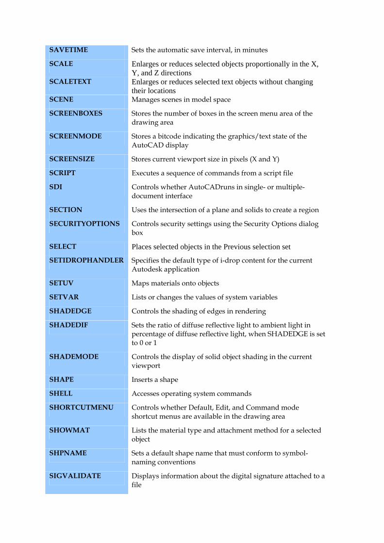
SAVETIME Sets the automatic save interval, in minutes
SCALE Enlarges or reduces selected objects proportionally in the X, Y, and Z directions
SCALETEXT Enlarges or reduces selected text objects without changing their locations
SCENE Manages scenes in model space
SCREENBOXES Stores the number of boxes in the screen menu area of the drawing area
SCREENMODE Stores a bitcode indicating the graphics/text state of the AutoCAD display
SCREENSIZE Stores current viewport size in pixels (X and Y)
SCRIPT Executes a sequence of commands from a script file
SDI Controls whether AutoCADruns in single- or multiple-document interface
SECTION Uses the intersection of a plane and solids to create a region
SECURITYOPTIONS Controls security settings using the Security Options dialog box
SELECT Places selected objects in the Previous selection set
SETIDROPHANDLER Specifies the default type of i-drop content for the current Autodesk application
SETUV Maps materials onto objects
SETVAR Lists or changes the values of system variables
SHADEDGE Controls the shading of edges in rendering
SHADEDIF Sets the ratio of diffuse reflective light to ambient light in percentage of diffuse reflective light, when SHADEDGE is set to 0 or 1
SHADEMODE Controls the display of solid object shading in the current viewport
SHAPE Inserts a shape
SHELL Accesses operating system commands
SHORTCUTMENU Controls whether Default, Edit, and Command mode shortcut menus are available in the drawing area
SHOWMAT Lists the material type and attachment method for a selected object
SHPNAME Sets a default shape name that must conform to symbol- naming conventions
SIGVALIDATE Displays information about the digital signature attached to a file
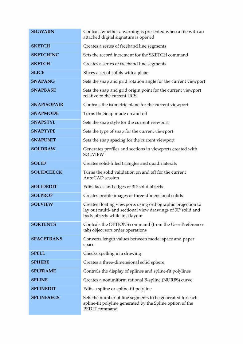
SIGWARN Controls whether a warning is presented when a file with an attached digital signature is opened
SKETCH Creates a series of freehand line segments
SKETCHINC Sets the record increment for the SKETCH command
SKETCH Creates a series of freehand line segments
SLICE Slices a set of solids with a plane
SNAPANG Sets the snap and grid rotation angle for the current viewport
SNAPBASE Sets the snap and grid origin point for the current viewport relative to the current UCS
SNAPISOPAIR Controls the isometric plane for the current viewport
SNAPMODE Turns the Snap mode on and off
SNAPSTYL Sets the snap style for the current viewport
SNAPTYPE Sets the type of snap for the current viewport
SNAPUNIT Sets the snap spacing for the current viewport
SOLDRAW Generates profiles and sections in viewports created with SOLVIEW
SOLID Creates solid-filled triangles and quadrilaterals
SOLIDCHECK Turns the solid validation on and off for the current AutoCAD session
SOLIDEDIT Edits faces and edges of 3D solid objects
SOLPROF Creates profile images of three-dimensional solids
SOLVIEW Creates floating viewports using orthographic projection to lay out multi- and sectional view drawings of 3D solid and body objects while in a layout
SORTENTS Controls the OPTIONS command (from the User Preferences tab) object sort order operations
SPACETRANS Converts length values between model space and paper space
SPELL Checks spelling in a drawing
SPHERE Creates a three-dimensional solid sphere
SPLFRAME Controls the display of splines and spline-fit polylines
SPLINE Creates a nonuniform rational B-spline (NURBS) curve
SPLINEDIT Edits a spline or spline-fit polyline
SPLINESEGS Sets the number of line segments to be generated for each spline-fit polyline generated by the Spline option of the PEDIT command
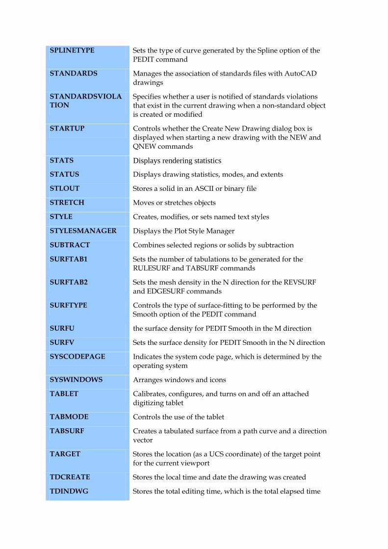
SPLINETYPE Sets the type of curve generated by the Spline option of the PEDIT command
STANDARDS Manages the association of standards files with AutoCAD drawings
STANDARDSVIOLATION
Specifies whether a user is notified of standards violations that exist in the current drawing when a non-standard object is created or modified
STARTUP Controls whether the Create New Drawing dialog box is displayed when starting a new drawing with the NEW and QNEW commands
STATS Displays rendering statistics
STATUS Displays drawing statistics, modes, and extents
STLOUT Stores a solid in an ASCII or binary file
STRETCH Moves or stretches objects
STYLE Creates, modifies, or sets named text styles
STYLESMANAGER Displays the Plot Style Manager
SUBTRACT Combines selected regions or solids by subtraction
SURFTAB1 Sets the number of tabulations to be generated for the RULESURF and TABSURF commands
SURFTAB2 Sets the mesh density in the N direction for the REVSURF and EDGESURF commands
SURFTYPE Controls the type of surface-fitting to be performed by the Smooth option of the PEDIT command
SURFU the surface density for PEDIT Smooth in the M direction
SURFV Sets the surface density for PEDIT Smooth in the N direction
SYSCODEPAGE Indicates the system code page, which is determined by the operating system
SYSWINDOWS Arranges windows and icons
TABLET Calibrates, configures, and turns on and off an attached digitizing tablet
TABMODE Controls the use of the tablet
TABSURF Creates a tabulated surface from a path curve and a direction vector
TARGET Stores the location (as a UCS coordinate) of the target point for the current viewport
TDCREATE Stores the local time and date the drawing was created
TDINDWG Stores the total editing time, which is the total elapsed time
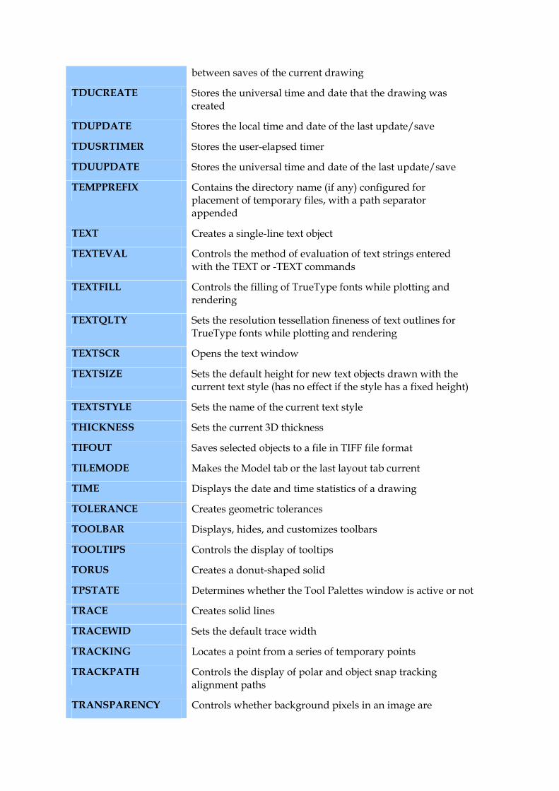
between saves of the current drawing
TDUCREATE Stores the universal time and date that the drawing was created
TDUPDATE Stores the local time and date of the last update/save
TDUSRTIMER Stores the user-elapsed timer
TDUUPDATE Stores the universal time and date of the last update/save
TEMPPREFIX Contains the directory name (if any) configured for placement of temporary files, with a path separator appended
TEXT Creates a single-line text object
TEXTEVAL Controls the method of evaluation of text strings entered with the TEXT or -TEXT commands
TEXTFILL Controls the filling of TrueType fonts while plotting and rendering
TEXTQLTY Sets the resolution tessellation fineness of text outlines for TrueType fonts while plotting and rendering
TEXTSCR Opens the text window
TEXTSIZE Sets the default height for new text objects drawn with the current text style (has no effect if the style has a fixed height)
TEXTSTYLE Sets the name of the current text style
THICKNESS Sets the current 3D thickness
TIFOUT Saves selected objects to a file in TIFF file format
TILEMODE Makes the Model tab or the last layout tab current
TIME Displays the date and time statistics of a drawing
TOLERANCE Creates geometric tolerances
TOOLBAR Displays, hides, and customizes toolbars
TOOLTIPS Controls the display of tooltips
TORUS Creates a donut-shaped solid
TPSTATE Determines whether the Tool Palettes window is active or not
TRACE Creates solid lines
TRACEWID Sets the default trace width
TRACKING Locates a point from a series of temporary points
TRACKPATH Controls the display of polar and object snap tracking alignment paths
TRANSPARENCY Controls whether background pixels in an image are
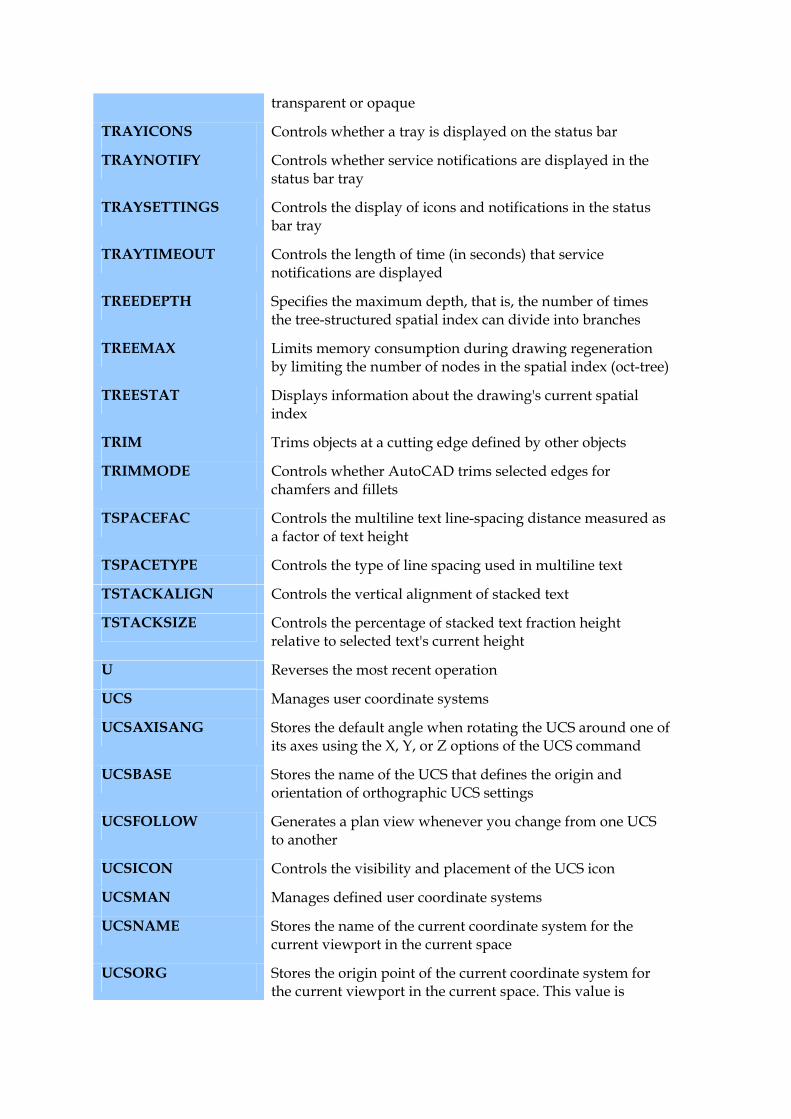
transparent or opaque
TRAYICONS Controls whether a tray is displayed on the status bar
TRAYNOTIFY Controls whether service notifications are displayed in the status bar tray
TRAYSETTINGS Controls the display of icons and notifications in the status bar tray
TRAYTIMEOUT Controls the length of time (in seconds) that service notifications are displayed
TREEDEPTH Specifies the maximum depth, that is, the number of times the tree-structured spatial index can divide into branches
TREEMAX Limits memory consumption during drawing regeneration by limiting the number of nodes in the spatial index (oct-tree)
TREESTAT Displays information about the drawing's current spatial index
TRIM Trims objects at a cutting edge defined by other objects
TRIMMODE Controls whether AutoCAD trims selected edges for chamfers and fillets
TSPACEFAC Controls the multiline text line-spacing distance measured as a factor of text height
TSPACETYPE Controls the type of line spacing used in multiline text
TSTACKALIGN Controls the vertical alignment of stacked text
TSTACKSIZE Controls the percentage of stacked text fraction height relative to selected text's current height
U Reverses the most recent operation
UCS Manages user coordinate systems
UCSAXISANG Stores the default angle when rotating the UCS around one of its axes using the X, Y, or Z options of the UCS command
UCSBASE Stores the name of the UCS that defines the origin and orientation of orthographic UCS settings
UCSFOLLOW Generates a plan view whenever you change from one UCS to another
UCSICON Controls the visibility and placement of the UCS icon
UCSMAN Manages defined user coordinate systems
UCSNAME Stores the name of the current coordinate system for the current viewport in the current space
UCSORG Stores the origin point of the current coordinate system for the current viewport in the current space. This value is
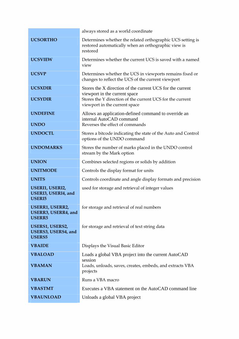
always stored as a world coordinate
UCSORTHO Determines whether the related orthographic UCS setting is restored automatically when an orthographic view is restored
UCSVIEW Determines whether the current UCS is saved with a named view
UCSVP Determines whether the UCS in viewports remains fixed or changes to reflect the UCS of the current viewport
UCSXDIR Stores the X direction of the current UCS for the current viewport in the current space
UCSYDIR Stores the Y direction of the current UCS for the current viewport in the current space
UNDEFINE Allows an application-defined command to override an internal AutoCAD command
UNDO Reverses the effect of commands
UNDOCTL Stores a bitcode indicating the state of the Auto and Control options of the UNDO command
UNDOMARKS Stores the number of marks placed in the UNDO control stream by the Mark option
UNION Combines selected regions or solids by addition
UNITMODE Controls the display format for units
UNITS Controls coordinate and angle display formats and precision
USERI1, USERI2, USERI3, USERI4, and USERI5
used for storage and retrieval of integer values
USERR1, USERR2, USERR3, USERR4, and USERR5
for storage and retrieval of real numbers
USERS1, USERS2, USERS3, USERS4, and USERS5
for storage and retrieval of text string data
VBAIDE Displays the Visual Basic Editor
VBALOAD Loads a global VBA project into the current AutoCAD session
VBAMAN Loads, unloads, saves, creates, embeds, and extracts VBA projects
VBARUN Runs a VBA macro
VBASTMT Executes a VBA statement on the AutoCAD command line
VBAUNLOAD Unloads a global VBA project
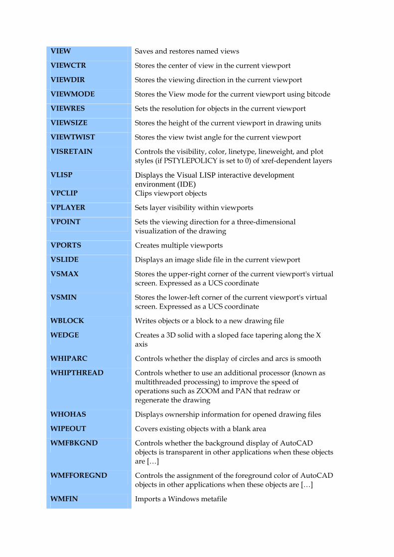
VIEW Saves and restores named views
VIEWCTR Stores the center of view in the current viewport
VIEWDIR Stores the viewing direction in the current viewport
VIEWMODE Stores the View mode for the current viewport using bitcode
VIEWRES Sets the resolution for objects in the current viewport
VIEWSIZE Stores the height of the current viewport in drawing units
VIEWTWIST Stores the view twist angle for the current viewport
VISRETAIN Controls the visibility, color, linetype, lineweight, and plot styles (if PSTYLEPOLICY is set to 0) of xref-dependent layers
VLISP Displays the Visual LISP interactive development environment (IDE)
VPCLIP Clips viewport objects
VPLAYER Sets layer visibility within viewports
VPOINT Sets the viewing direction for a three-dimensional visualization of the drawing
VPORTS Creates multiple viewports
VSLIDE Displays an image slide file in the current viewport
VSMAX Stores the upper-right corner of the current viewport's virtual screen. Expressed as a UCS coordinate
VSMIN Stores the lower-left corner of the current viewport's virtual screen. Expressed as a UCS coordinate
WBLOCK Writes objects or a block to a new drawing file
WEDGE Creates a 3D solid with a sloped face tapering along the X axis
WHIPARC Controls whether the display of circles and arcs is smooth
WHIPTHREAD Controls whether to use an additional processor (known as multithreaded processing) to improve the speed of operations such as ZOOM and PAN that redraw or regenerate the drawing
WHOHAS Displays ownership information for opened drawing files
WIPEOUT Covers existing objects with a blank area
WMFBKGND Controls whether the background display of AutoCAD objects is transparent in other applications when these objects are […]
WMFFOREGND Controls the assignment of the foreground color of AutoCAD objects in other applications when these objects are […]
WMFIN Imports a Windows metafile
WMFOPTS Sets options for WMFIN
WMFOUT Saves objects to a Windows metafile
WORLDUCS Indicates whether the UCS is the same as the WCS
WORLDVIEW Determines whether input to the 3DORBIT, DVIEW, and VPOINT commands is relative to the WCS (default) or the current UCS
WRITESTAT Indicates whether a drawing file is read-only or can be written to
XATTACH Attaches an external reference to the current drawing
XBIND Binds one or more definitions of named objects in an xref to the current drawing
XCLIP Defines an xref or block clipping boundary and sets the front or back clipping planes
XCLIPFRAME Controls the visibility of xref clipping boundaries
XEDIT Controls whether the current drawing can be edited in-place when being referenced by another drawing
XFADECTL Controls the fading intensity percentage for references being edited in-place
XLINE Creates an infinite line
XLOADCTL Turns xref demand-loading on and off, and controls whether referenced drawing files are opened or copies of referenced drawing files are opened
XLOADPATH Creates a path for storing temporary copies of demand-loaded xref files
XLINE Creates an infinite line
XPLODE Breaks a compound object into its component objects
XREF Controls external references to drawing files
XREFCTL Controls whether AutoCAD writes external reference log (XLG) files
XREFNOTIFY Controls the notification for updated or missing xrefs
ZOOM Increases or decreases the apparent size of objects in the current viewport
ZOOMFACTOR Sets the zoomfactor