Embed Size (px)
Citation preview
Pole Mounted Distribution Transformer
T HR EL 16001 SP
Specification
Version 1.0
Issue date: 16 May 2018
© State of NSW through Transport for NSW 2018

T HR EL 16001 SP Pole Mounted Distribution Transformer
Version 1.0 Issue date: 16 May 2018
Important message This document is one of a set of standards developed solely and specifically for use on
Transport Assets (as defined in the Asset Standards Authority Charter). It is not suitable for any
other purpose.
The copyright and any other intellectual property in this document will at all times remain the
property of the State of New South Wales (Transport for NSW).
You must not use or adapt this document or rely upon it in any way unless you are providing
products or services to a NSW Government agency and that agency has expressly authorised
you in writing to do so. If this document forms part of a contract with, or is a condition of
approval by a NSW Government agency, use of the document is subject to the terms of the
contract or approval. To be clear, the content of this document is not licensed under any
Creative Commons Licence.
This document may contain third party material. The inclusion of third party material is for
illustrative purposes only and does not represent an endorsement by NSW Government of any
third party product or service.
If you use this document or rely upon it without authorisation under these terms, the State of
New South Wales (including Transport for NSW) and its personnel does not accept any liability
to you or any other person for any loss, damage, costs and expenses that you or anyone else
may suffer or incur from your use and reliance on the content contained in this document. Users
should exercise their own skill and care in the use of the document.
This document may not be current and is uncontrolled when printed or downloaded. Standards
may be accessed from the Transport for NSW website at www.transport.nsw.gov.au
For queries regarding this document, please email the ASA at [email protected] or visit www.transport.nsw.gov.au © State of NSW through Transport for NSW 2018

T HR EL 16001 SP Pole Mounted Distribution Transformer
Version 1.0 Issue date: 16 May 2018
Standard governance
Owner: Lead Electrical Engineer, Asset Standards Authority
Authoriser: Chief Engineer, Asset Standards Authority
Approver Executive Director, Asset Standards Authority on behalf of the ASA Configuration Control Board
Document history
Version Summary of changes
1.0 First issue
© State of NSW through Transport for NSW 2018 Page 3 of 29

T HR EL 16001 SP Pole Mounted Distribution Transformer
Version 1.0 Issue date: 16 May 2018
Preface
The Asset Standards Authority (ASA) is a key strategic branch of Transport for NSW (TfNSW).
As the network design and standards authority for NSW Transport Assets, as specified in the
ASA Charter, the ASA identifies, selects, develops, publishes, maintains and controls a suite of
requirements documents on behalf of TfNSW, the asset owner.
The ASA deploys TfNSW requirements for asset and safety assurance by creating and
managing TfNSW's governance models, documents and processes. To achieve this, the ASA
focuses on four primary tasks:
• publishing and managing TfNSW's process and requirements documents including TfNSW
plans, standards, manuals and guides
• deploying TfNSW's Authorised Engineering Organisation (AEO) framework
• continuously improving TfNSW’s Asset Management Framework
• collaborating with the Transport cluster and industry through open engagement
The AEO framework authorises engineering organisations to supply and provide asset related
products and services to TfNSW. It works to assure the safety, quality and fitness for purpose of
those products and services over the asset's whole-of-life. AEOs are expected to demonstrate
how they have applied the requirements of ASA documents, including TfNSW plans, standards
and guides, when delivering assets and related services for TfNSW.
Compliance with ASA requirements by itself is not sufficient to ensure satisfactory outcomes for
NSW Transport Assets. The ASA expects that professional judgement be used by competent
personnel when using ASA requirements to produce those outcomes.
About this document
This document specifies the requirements for pole mounted distribution transformers that are
used on the RailCorp network.
This document supersedes the RailCorp document EP 16 00 00 01 SP Pole Mounted
Distribution Transformer, version 3.1. This specification is a first issue.
© State of NSW through Transport for NSW 2018 Page 4 of 29

T HR EL 16001 SP Pole Mounted Distribution Transformer
Version 1.0 Issue date: 16 May 2018
Table of contents 1. Introduction .............................................................................................................................................. 7
2. Purpose .................................................................................................................................................... 7 2.1. Scope ..................................................................................................................................................... 7 2.2. Application ............................................................................................................................................. 7
3. Reference documents ............................................................................................................................. 8
4. Terms and definitions ............................................................................................................................. 9
5. ASA type approval ................................................................................................................................. 10
6. Service conditions ................................................................................................................................. 10
7. Performance requirements ................................................................................................................... 10 7.1. Electrical characteristics ...................................................................................................................... 10 7.2. Rated insulation level ........................................................................................................................... 11 7.3. Minimum energy performance standards (MEPS) .............................................................................. 12
8. Technical requirements ........................................................................................................................ 12 8.1. Temperature rise limits at rated power ................................................................................................ 12 8.2. Sound level .......................................................................................................................................... 12 8.3. Radio interference ............................................................................................................................... 12 8.4. Liquid-immersed configuration............................................................................................................. 12 8.5. Tapping switch ..................................................................................................................................... 13 8.6. Rating plate .......................................................................................................................................... 13 8.7. HV terminal arrangement ..................................................................................................................... 13 8.8. Attachment points for surge arrestor mounting bracket ...................................................................... 14 8.9. LV terminal arrangement ..................................................................................................................... 14 8.10. Earth terminals ................................................................................................................................. 14 8.11. Transformer screen ......................................................................................................................... 15 8.12. Lifting attachments ........................................................................................................................... 15 8.13. Hangers ........................................................................................................................................... 15 8.14. Finish ............................................................................................................................................... 16 8.15. Painting ............................................................................................................................................ 16 8.16. Labelling........................................................................................................................................... 17
9. Tests ....................................................................................................................................................... 17 9.1. Type tests ............................................................................................................................................ 17 9.2. Routine tests ........................................................................................................................................ 17
Appendix A Whole-of-life cost ............................................................................................................... 18
Appendix B Data set associated with the equipment ......................................................................... 19 B.1. Drawings and information .................................................................................................................... 19 B.2. Technical schedule .............................................................................................................................. 19 B.3. Life cycle costing ................................................................................................................................. 19 B.4. Test results .......................................................................................................................................... 19
Appendix C Transformer configurations .............................................................................................. 21 © State of NSW through Transport for NSW 2018 Page 5 of 29

T HR EL 16001 SP Pole Mounted Distribution Transformer
Version 1.0 Issue date: 16 May 2018
Appendix D Technical schedule ............................................................................................................ 22 D.1. Transformer details .............................................................................................................................. 22 D.2. Drawings and information to be submitted with the tender ................................................................. 26
Appendix E Integrated system support requirements ........................................................................ 28 E.1. Equipment supplier deliverable ........................................................................................................... 28 E.2. Operation and maintenance manual ................................................................................................... 28
Appendix F Information requirements for the request for tender ......................................................... 29 F.1. Information to be sought from the tenderer ......................................................................................... 29 F.2. Information to be supplied at time of order .......................................................................................... 29
© State of NSW through Transport for NSW 2018 Page 6 of 29

T HR EL 16001 SP Pole Mounted Distribution Transformer
Version 1.0 Issue date: 16 May 2018
1. Introduction This document details the whole-of-life performance requirements for the purchase of pole
mounted distribution transformers for use in the RailCorp electrical network.
It covers two-phase and three-phase transformers with primary voltages of 11 kV and 33 kV and
secondary voltages of 125 V, 250 V, and 433 V.
The transformers covered by this document are for the supply of low voltage electricity to
railway stations, signals, workshops and various other ac loads from the RailCorp HV
distribution system or from another distribution network operator's high voltage (HV) distribution
system. They are not used for supplying dc traction loads.
2. Purpose The purpose of this document is to specify the requirements for pole mounted distribution
transformers to enable suitable equipment to be procured for use in the RailCorp electrical
network.
2.1. Scope This document provides the specifications of two-phase and three-phase distribution
transformers with primary voltages of 11 kV and 33 kV and secondary voltages of 125 V, 250 V,
and 433 V designed for pole mounted installation on railway distribution systems.
This document has been prepared on the basis of a liquid-immersed configuration. However, it
is not intended to preclude a dry-type transformer complying with the relevant provisions.
2.2. Application The requirements of this document apply to the purchase of all new pole mounted distribution
transformers for use in the RailCorp electrical network. These requirements are applicable from
the date of issue of this specification.
This document may be used for the procurement of transformers to replace existing 33 kV pole
mounted transformers.
New installations of 33 kV pole mounted transformers are not permitted in the RailCorp
electrical network.
In addition to the requirements of this specification, asset decisions should take into account the
life cycle cost requirements in T MU AM 01001 ST Life Cycle Costing. TfNSW is concerned to
keep lifetime costs, rather than purchase price, to a minimum. In that regard equipment that
requires the minimum possible maintenance over its lifetime is preferred.
© State of NSW through Transport for NSW 2018 Page 7 of 29

T HR EL 16001 SP Pole Mounted Distribution Transformer
Version 1.0 Issue date: 16 May 2018
If, when using this specification, it is considered that the intent of stated requirements is not
clear, a clarification should be sought from the ASA Lead Electrical Engineer.
3. Reference documents The following documents are cited in the text. For dated references, only the cited edition
applies. For undated references, the latest edition of the referenced document applies.
International standards
EN 50180 Bushings above 1kV up to 52kV and from 250A to 3.15kA for liquid filled
transformers
EN 50181 Plug-in Type Bushings above 1kV up to 52kV and from 250A to 2.50kA for
equipment other than liquid filled transformers
Australian standards
AS 1767.1 Insulating liquids Part 1 Specification for unused mineral insulating oils for
transformers and switchgear
AS/NZS 2344 Limits of electromagnetic interference from overhead a.c. powerlines and high
voltage equipment installations in the frequency range 0.15 MHz to 1000 MHz
AS 2374.1.2-2003 Power transformers - Minimum Energy Performance Standard (MEPS)
requirements for distribution transformers
AS 2700 Colour standards for general purposes
AS/NZS 60076.1:2014- Power transformers - General
AS/NZS 60076.2:2013- Power transformers - Temperature rise for liquid-immersed transformers
AS/NZS 60076.3 Power transformers – Insulation levels, dielectric tests and external
clearances in air
AS 60076.4 Power transformers – Guide to the lightning impulse and switching impulse testing
– Power transformers and reactors
AS/NZS 60076.5 Power transformers – Ability to withstand short circuit
AS/NZS 60076.10:2009 Power transformers – Part 10: Determination of sound levels
AS/NZS 60137:2008 Insulated bushings for alternating voltages above 1000 V
Transport for NSW standards
EP 00 00 00 13 SP Electrical Power Equipment - Design Ranges of Ambient Conditions
EP 00 00 00 15 SP Common Requirements for Electrical Power Equipment
EP 02 00 00 01 SP Transformer Loss Evaluation
© State of NSW through Transport for NSW 2018 Page 8 of 29

T HR EL 16001 SP Pole Mounted Distribution Transformer
Version 1.0 Issue date: 16 May 2018
T HR EL 00002 PR Electrical Power Equipment - Integrated Support Requirements
T MU AM 01001 ST Life Cycle Costing
T MU MD 00005 GU Type Approval of Products
T MU MD 00006 ST Engineering Drawings and CAD Requirements
Transport standard drawings
EL0003000 Substations 33 kV / 415 V 3 phase transformer single pole structure arrangement
(not to be used for new installations)
EL0025064 Substations 11 kV / 415 V transformer. Single pole structure arrangement
EL0025111 Substations 11 kV / 433 V transformer single pole structure, transformer mounting
details
EL0037020 Train signalling 11 kV / 120 V transformer. Single pole structure arrangement
EL0037164 Train signalling. 11 kV / 120 V transformer single pole structure details
EL0289609 Pole Mounted Substation Screened 11kV Interconnecting Cable Assembly Details
EL0435620 Pole Mounted Substation 11 kV / 433-250 V and 11 kV / 250-120V Transformer –
Arrangement
EL0441056 Pole Mounted Substation 11kV Boric Acid Expulsion Dropout Fuse Arrangement
EL0441057 Pole Mounted Substation Earth Clamp Parking Bar Fitting Details
EL0610718 Pole Mounted Substation Earthing Arrangement
4. Terms and definitions The following terms and definitions apply in this document:
AEO Authorised Engineering Organisation
ASA Asset Standards Authority
distribution transformer a transformer that transforms and controls the system voltages to a
secondary voltage of nominally 433 V, 250 V or 125 V
HV high voltage
LV low voltage
NB normal bore (of pipe)
ONAN Oil Natural, Air Natural cooling; the transformer windings and core are oil cooled and the
oil is air cooled, without the use of pumps or fans
pole mounted transformer is mounted on a pole supporting an overhead line
© State of NSW through Transport for NSW 2018 Page 9 of 29

T HR EL 16001 SP Pole Mounted Distribution Transformer
Version 1.0 Issue date: 16 May 2018
primary winding the winding that receives the active power from the supply system, usually the
winding having the highest rated voltage
principal tapping the tapping to which the rated quantities are related
RFT request for tender
two-phase system where the secondary of a transformer is a two wire system, that is it has a
voltage of 250 V or 125 V, and the primary winding of the transformer is connected across two
phases of the high voltage system
Note: The definitions given in AS 60076 apply.
5. ASA type approval Transformers procured to this specification require type approval by Asset Standards Authority
(ASA) prior to being connected to the RailCorp electrical network.
The ASA process for type approval is given in T MU MD 00005 GU Type Approval of Products.
6. Service conditions The distribution transformer shall be suitable for outdoor pole mounting.
The pole mounted distribution transformers shall be suitable for operation in the ambient
conditions set out in the relevant sections of EP 00 00 00 13 SP Electrical Power Equipment –
Design Ranges of Ambient Conditions.
7. Performance requirements The pole mounted transformers covered in this document shall comply with the performance
requirements as stated in Section 7.1, Section 7.2, and Section 7.3.
Where not specifically detailed in this document, the performance characteristics of the
transformer shall be in accordance with AS/NZS 60076 Power transformers (all parts).
7.1. Electrical characteristics Table 1 details the main electrical characteristics of pole mounted transformers. Refer to
Appendix C for figurative representation of the transformer configurations.
Table 1 - Transformer electrical characteristics
Technical parameter 11 kV transformers 33 kV transformers
Rated frequency 50 Hz 50 Hz
No. of windings Two winding or three winding Two winding
© State of NSW through Transport for NSW 2018 Page 10 of 29

T HR EL 16001 SP Pole Mounted Distribution Transformer
Version 1.0 Issue date: 16 May 2018
Technical parameter 11 kV transformers 33 kV transformers
No. of phases two-phase (ph to ph) or three-phase
two-phase (ph to ph) or three-phase
Vector group Dyn1 Dyn1
Rated voltage for HV winding 11,000 V (ph – ph) 33,000 V (ph – ph)
Rated voltage for LV winding
250 V or 125 V or 2 x 125 V for phase to phase 433 V for three-phase
250 V or 125 V for phase to phase 433 V for three-phase
Rated voltage ratio (no-load)
11,000(phase-phase)/125 V 11,000(phase-phase)/250 V 11,000/433 V (three-phase)
33,000(phase-phase)/125 V 33,000(phase-phase)/250 V 33,000/433 V (three-phase)
Tappings on HV winding 0%, ± 2.5%, and ± 5% 0%, ± 2.5%, and ± 5%
Neutral terminal
Star point or neutral of lower voltage winding connected to a bushing and fully insulated from earth.
Star point or neutral of lower voltage winding connected to a bushing and fully insulated from earth.
Inter-winding screen Option – provide if stipulated. Refer to Section 8.11
Option – provide if stipulated. Refer to Section 8.11
Rated power (preferred ratings, other sizes subject to TfNSW’s approval)
Single-phase: 25 kVA Three-phase: 75 kVA, 100 kVA, 200 kVA
Single-phase: 25 kVA Three-phase: 75 kVA, 100 kVA, 200 kVA
Impedance 3.3% for 25 kVA 4% for 75 kVA, 100 kVA, 200 kVA
3.3% for 25 kVA 4% for 75 kVA, 100 kVA, 200 kVA
Type of cooling ONAN ONAN
7.2. Rated insulation level The distribution transformer insulation system shall be suitable for connection to a HV system
that is not effectively earthed. The rated insulation level shall be in accordance with the values
specified in Table 2.
Table 2 - Rated insulation level
Rated voltage of winding
System highest voltage (Um)
Rated insulation level for lightning impulse withstand voltage
Rated insulation level for Power frequency (one minute, dry, flashover) voltage
125 Vrms– 433 Vrms
1.1 kVrms N/A 5 kVrms
11 kVrms 12 kVrms 95 kVpk 28 kVrms
33 kVrms 36 kVrms 200 kVpk 70 kVrms
© State of NSW through Transport for NSW 2018 Page 11 of 29

T HR EL 16001 SP Pole Mounted Distribution Transformer
Version 1.0 Issue date: 16 May 2018
7.3. Minimum energy performance standards (MEPS) The distribution transformer shall meet the minimum power requirements for transformer
efficiency at 50% load as specified in Table 1 of AS 2374.1.2-2003
8. Technical requirements The pole mounted transformers covered in this document shall comply with the technical
requirements as stated in Section 8.1 through Section 8.16.
8.1. Temperature rise limits at rated power The temperature rise when the transformer is operated continuously at rated power shall not
exceed the limits set out in Table 1 of AS/NZS 60076.2:2013.
8.2. Sound level The transformer sound level shall be measured in accordance with AS/NZS 60076.10:2009 and
shall comply with the standard limit in accordance with Annex ZA of AS/NZS 60076.10:2009.
8.3. Radio interference The transformer shall comply with the limits of radio interference as specified in AS 2344 Limits
of electromagnetic interference from overhead a.c. powerlines and high voltage equipment
installations in the frequency range 0.15 MHz to 1000 MHz.
8.4. Liquid-immersed configuration The liquid shall be insulating oil complying with the requirements of AS 1767.1 Insulating liquids
Part 1 Specification for unused mineral insulating oils for transformers and switchgear. The
insulating oil shall be certified to contain less than 1 ppm of polychlorinated biphenyl (PCB)
material.
The liquid preservation systems shall be a sealed-tank system with gas cushion. The space
above the oil shall be filled with inert gas or dry air.
The gland for the tapping switch shall be located below cold oil level.
The tank cover and bracing shall be designed to prevent the accumulation of water.
The transformers shall be thoroughly dried out at the manufacturing facility and shall be
delivered to site with oil to the correct level and ready for service. All transformers shall be
vacuum filled. The degree of vacuum applied to the production units shall be identical to that
applied to the units that are type tested. The moisture content of the oil shall be less than
25 ppm at the time of filling.
© State of NSW through Transport for NSW 2018 Page 12 of 29

T HR EL 16001 SP Pole Mounted Distribution Transformer
Version 1.0 Issue date: 16 May 2018
8.5. Tapping switch An externally operated off-circuit tapping switch shall be provided.
Provision shall be made for locking the tapping switch in position.
8.6. Rating plate The rating plate shall meet the requirements of Section 8 of AS/NZS 60076.1:2014, and shall
include a diagram of connections. The diagram of connections shall include any inter-winding
screen and the associated terminal.
A terminal marking plate complying with the requirements of Appendix ZB subsection ZB7 of
AS/NZS 60076.1:2014 shall also be attached to the transformer.
The plates shall not be attached to a removable cover.
8.7. HV terminal arrangement The requirements for the HV terminal arrangements for pole mounted distribution transformers
are detailed in Section 8.7.1, Section 8.7.2, and Section 8.7.3.
8.7.1. HV terminal options Where the transformer is for use in an 11 kV or 33 kV switch-frame application, then exposed
bushings shall be provided for the HV terminals. Typical switch-frame arrangements as installed
in the RailCorp electrical network are shown in drawings EL0003000, EL0025064, and
EL0037020.
If the transformer is for a 11 kV cable connected application then separable deadbreak
connectors shall be provided for the HV terminals. A typical cable connected arrangement
approved for use in the RailCorp electrical network is shown in drawing EL0435620.
8.7.2. Exposed bushings The position of the primary winding terminal bushings shall be on the side of the transformer
remote from the pole. The bushings shall comply with AS/NZS 60137:2008 for normally polluted
atmosphere.
The minimum clearances provided in Table 3 shall apply for connections using lugs or terminals
not insulated to the appropriate voltage.
Table 3 – Clearances between HV terminals
33 kV terminals 11 kV terminals
Between different phases 460 mm 250 mm
Between phase and earthed metal 380 mm 160 mm © State of NSW through Transport for NSW 2018 Page 13 of 29

T HR EL 16001 SP Pole Mounted Distribution Transformer
Version 1.0 Issue date: 16 May 2018
8.7.3. Separable connectors
The position of the primary winding terminal deadbreak connector shall be on the side of the
transformer remote from the pole. The centres of the deadbreak connector shall be not more
than 200 mm below the top of the transformer tank.
The deadbreak connector shall be 12 kV Deadbreak Connector - Type A - 250 amp pin
interface, complete with stainless steel bail as described in standards EN 50180 Bushings
above 1kV up to 52kV and from 250A to 3.15kA for liquid filled transformers and EN 50181
Plug-in Type Bushings above 1kV up to 52kV and from 250A to 2.50kA for equipment other
than liquid filled transformers suitable for use with 12 kV Deadbreak Elbow - Type A - 250 amp
pin interface.
8.8. Attachment points for surge arrestor mounting bracket Where the transformer is fitted with exposed bushings, attachment points shall be provided for a
surge arrestor mounting bracket such that surge arrestors can be mounted adjacent to the
bushings.
8.9. LV terminal arrangement The position of the secondary winding terminal bushings shall be on the left hand end of the
transformer as viewed from the side containing the primary winding bushings. The bushings
shall comply with AS/NZS 60137:2008 for normally polluted atmosphere.
The minimum clearances provided in Table 4 shall apply for connections using lugs or terminals
not insulated to the appropriate voltage.
Table 4 – Clearances between LV terminals
415 V / 433 V terminals 125 V / 250 V terminals
Between different phases 110 mm 75 mm
Between phase and earthed metal 60 mm 60 mm
Transformers that have dual secondary windings (2 x 125 V windings that can be connected in
parallel for 125 V, or in series for 250 V operation) shall have four equally spaced LV terminal
bushings in a row and arranged as follows: S11 – S21 – S12 – S22.
8.10. Earth terminals A suitable earthing terminal shall be located near the bottom of the tank.
In the case of a transformer fitted with separable connectors, a suitable earth terminal shall also
be provided for connection of the drain wires from the semi-conducting screens in the
deadbreak connector elbows.
© State of NSW through Transport for NSW 2018 Page 14 of 29

T HR EL 16001 SP Pole Mounted Distribution Transformer
Version 1.0 Issue date: 16 May 2018
8.11. Transformer screen Transformers used solely for supplying unearthed installations, such as signalling locations,
shall be provided with a copper or aluminium metal screen located between the primary and
secondary windings.
The screen shall be not less than 0.5 mm in thickness and shall be connected to a special
insulated terminal. The metal screen shall be arranged to prevent leakage or capacitive
coupling from any part of the primary windings to any part of the secondary windings of the
transformers.
The transformer shall be designed on the basis that the inter-winding screen is solidly earthed.
8.12. Lifting attachments Suitable lifting lugs shall be provided for lifting the transformer.
8.13. Hangers The transformer shall be provided with hangers for cross arm mounting, on either one of the
following:
• 102 mm x 51 mm steel channel cross arm
• 102 mm x 102 mm timber cross arm
The particular mounting option shall be nominated when the transformer is procured.
For 11 kV switch frame arrangements that are in accordance with drawing EL0025064, the
dimensions of the transformer mounting details shall be in accordance with drawing
EL0025111.
For 11 kV switch frame arrangements that are in accordance with drawing EL0037020, the
dimensions of the transformer mounting details shall be in accordance with drawing
EL0037164.
For cable connected 11 kV arrangements that are in accordance with drawing EL0435620, the
transformer mounting details shall be appropriate to interface with the arrangement shown at
Detail 1 on drawing EL0435620. The down-turn on the hanger hooks shall be 130 mm internal.
The horizontal offset of the hanger brackets shall be adjustable to suit poles of different
diameters. This will allow the hanger hooks to fit between the pole band arrangements on larger
poles and outside the pole band arrangements on smaller poles. For fitting between the pole
bands, the dimension across the outside of the hanger hooks shall be less than 450 mm. For
fitting outside the pole bands, the dimension between the insides of the hanger hooks shall be
greater than 610 mm. The hanger hooks shall be equidistant from the axis of the centreline of
the transformer.
© State of NSW through Transport for NSW 2018 Page 15 of 29

T HR EL 16001 SP Pole Mounted Distribution Transformer
Version 1.0 Issue date: 16 May 2018
In other cases, the particular transformer mounting arrangement required shall be determined to
suit the pole arrangement. Refer to the following drawings for more information:
• EL0037164 Train signalling. 11 kV / 120 V transformer single pole structure details
• EL0025111 Substations 11 kV / 433 V transformer single pole structure, transformer
mounting details
• EL0003000 Substations 33 kV / 415 V 3 phase transformer single pole structure
arrangement
Note: EL0003000 is not to be used for new installations
• EL0025064 Substations 11 kV / 415 V transformer. Single pole structure arrangement
• EL0037020 Train signalling 11 kV / 120 V transformer. Single pole structure arrangement
• EL0435620 Pole Mounted Substation 11 kV / 433-250 V and 11 kV / 250-120V
Transformer – Arrangement
• EL0610718 Pole Mounted Substation Earthing Arrangement
• EL0289609 Pole Mounted Substation Screened 11kV Interconnecting Cable Assembly
Details
• EL0441056 Pole Mounted Substation 11kV Boric Acid Expulsion Dropout Fuse
Arrangement
• EL0441057 Pole Mounted Substation Earth Clamp Parking Bar Fitting Details
8.14. Finish All welds shall be made smooth, rough edges rounded and weld splatter removed. The internal
and external surfaces shall be prepared and the paint applied strictly in accordance with the
manufacturer’s instructions. The finished surface shall be in a suitable condition to provide good
adhesion properties for the primary coat.
The preparation and method of application for the finish shall be suitable to ensure the
transformer is free of corrosion for the design life of the transformer.
8.15. Painting Painting of the transformer external surfaces shall be in accordance with EP 00 00 00 15 SP
Common Requirements for Electrical Power Equipment.
The outside surface of the transformer shall be painted Storm Grey, colour No. 42 in
accordance with AS 2700 Colour standards for general purposes.
© State of NSW through Transport for NSW 2018 Page 16 of 29

T HR EL 16001 SP Pole Mounted Distribution Transformer
Version 1.0 Issue date: 16 May 2018
8.16. Labelling Marking and labelling of the transformer shall be in accordance with the requirements of
EP 00 00 00 15 SP.
In addition to the requirements of EP 00 00 00 15 SP, the transformer rated voltage and
capacity shall be stencilled in black numerals onto the tank where it can be easily seen from the
ground. The numerals shall be 75 mm high.
9. Tests Section 9.1 and Section 9.2 provide the list of tests to be performed on the transformer.
9.1. Type tests The following type tests shall be performed on the transformer:
• short circuit test in compliance to AS/NZS 60076.5
• temperature rise test in compliance to AS/NZS 60076.2
• impulse voltage withstand test in compliance to AS 60076.4
• sound level test in compliance to AS/NZS 60076.10
• partial discharge test in compliance to AS/NZS 60076.3
Type test certificates of the performed tests shall be provided by the manufacturer. ASA may
accept type test certificates that have been previously conducted on similar transformers.
9.2. Routine tests The following routine tests shall be carried out on each transformer supplied:
• measurement of winding resistance in compliance to AS/NZS 60076.1
• measurement of voltage ratio and check of phase displacement in compliance to AS/NZS
60076.1
• measurement of short circuit impedance and load loss in compliance to AS/NZS 60076.1
• measurement of no-load loss and current in compliance to AS/NZS 60076.1
• induced over -voltage withstand in compliance to AS/NZS 60076.3
• separate source voltage withstand in compliance to AS/NZS 60076.3
• insulation resistance in compliance to AS/NZS 60076.3
• insulating oil in compliance to AS 1767.1
Relevant tests listed in EP 00 00 00 15 SP shall also be performed on the transformer. © State of NSW through Transport for NSW 2018 Page 17 of 29

T HR EL 16001 SP Pole Mounted Distribution Transformer
Version 1.0 Issue date: 16 May 2018
Appendix A Whole-of-life cost This appendix is provided for use by the AEO in assessing the whole-of-life cost.
The selection of the most suitable transformer design will be made on the basis of minimising
the whole-of-life cost. The following factors shall be considered in determining this and evidence
of their consideration shall be documented:
• cost of changes to the technical maintenance plan and service schedules or the creation of
new manuals and schedules
• cost of decommissioning and disposal
• cost of installation
• cost of inventory spares
• cost of maintenance
• cost of modifications to other parts of the installation
• cost of replacement parts
• cost of special tools
• cost of staff training
• discount rate
• electrical losses
• environmental costs
• initial purchase price
• lifetime of equipment
• reliability and cost of consequential damage after failure
• cost of optional tests
If this transformer has not previously been type approved by ASA in accordance with
T MU MD 00005 GU, then the costs for this process shall be included in the whole-of-life cost.
© State of NSW through Transport for NSW 2018 Page 18 of 29
T HR EL 16001 SP Pole Mounted Distribution Transformer
Version 1.0 Issue date: 16 May 2018
Appendix B Data set associated with the equipment
The data specified in Appendix B.1 to Appendix B.4 shall be supplied by the manufacturer and
maintained for the transformer. This data shall remain the property of TfNSW.
B.1. Drawings and information All drawings shall conform to the requirements of T MU MD 00006 ST Engineering Drawings
and CAD Requirements. The following drawings are required:
• arrangement drawings
Final arrangement drawings with full details and location of all items.
• pole attachment drawings
Pole attachment drawings showing how the transformer is attached to the pole.
• rating plate
Drawings of the rating plate as required in Section 8.6. Details shown on these drawings
shall not vary from that shown on the plates fixed to the transformer.
These drawings shall bear the transformer serial numbers of all units.
The calculation of inrush current is also required.
B.2. Technical schedule The information listed in the technical schedule in Appendix D, shall be supplied by the
manufacturer and maintained for each transformer.
B.3. Life cycle costing All the data and assumptions pertaining to the determination of the whole-of-life cost
calculations of the transformer shall be recorded including the transformer loss calculations as
detailed in EP 02 00 00 01 SP Transformer Loss Evaluation.
B.4. Test results The results of all tests, including routine, type, special, acceptance, periodic and corrective
maintenance tests shall be recorded and maintained.
Routine test certificates showing the results of each test performed shall be supplied in
duplicate and electronically, in English, and maintained for the life of the transformer.
© State of NSW through Transport for NSW 2018 Page 19 of 29

T HR EL 16001 SP Pole Mounted Distribution Transformer
Version 1.0 Issue date: 16 May 2018
Type test certificates showing the results of each test shall be supplied in duplicate and
electronically, in English, and maintained for the life of the equipment.
© State of NSW through Transport for NSW 2018 Page 20 of 29
T HR EL 16001 SP Pole Mounted Distribution Transformer
Version 1.0 Issue date: 16 May 2018
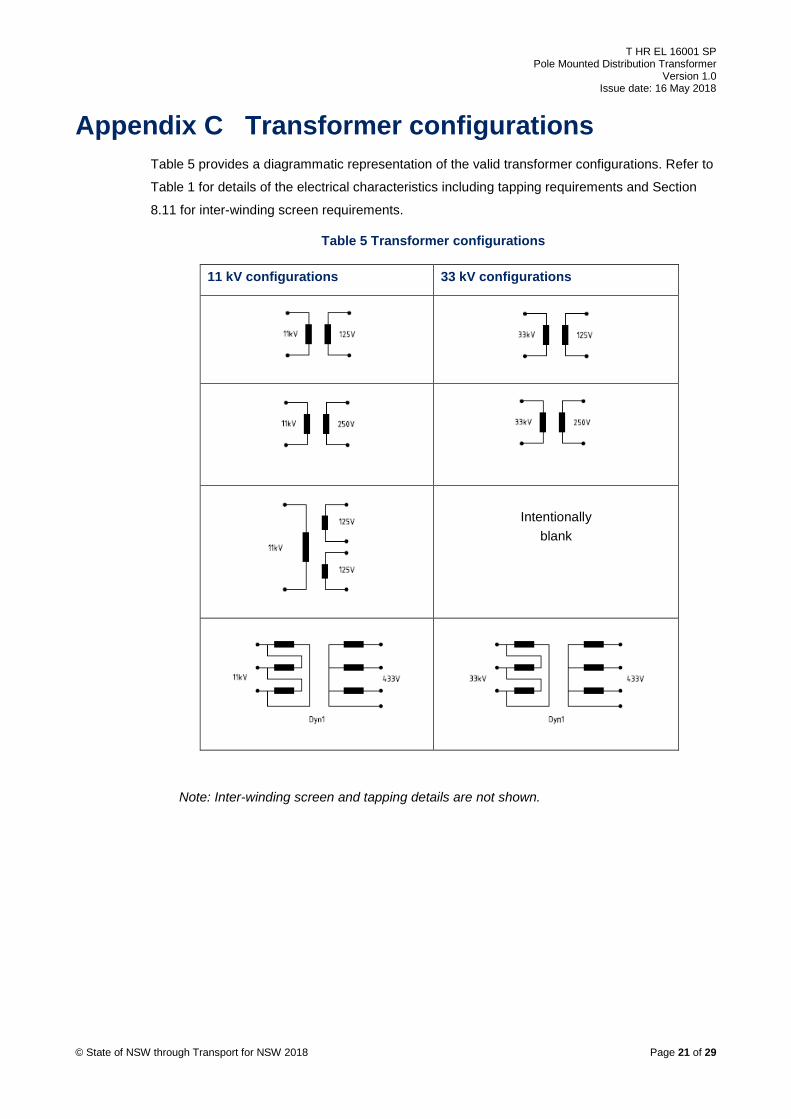
Appendix C Transformer configurations Table 5 provides a diagrammatic representation of the valid transformer configurations. Refer to
Table 1 for details of the electrical characteristics including tapping requirements and Section
8.11 for inter-winding screen requirements.
Table 5 Transformer configurations
11 kV configurations 33 kV configurations
Intentionally
blank
© State of NSW through Transport for NSW 2018 Page 21 of 29
Note: Inter-winding screen and tapping details are not shown.

T HR EL 16001 SP Pole Mounted Distribution Transformer
Version 1.0 Issue date: 16 May 2018
Appendix D Technical schedule Appendix D.1 contains requirements for provision of transformer details. Appendix D.2 contains
requirements regarding drawings and other information to be submitted with the tender.
D.1. Transformer details The tenderer shall supply the information listed in this technical schedule with the tender, for
each type of transformer.
Table 6 – Transformer details
Transformer details Answer
Name of manufacturer
Country of manufacturer
Number of phases
Rated primary voltage V
Rated secondary voltage V
Rated power kVA
Rated input frequency Hz
Rated input current A
Rated output current A
Inrush current A
Connection vector symbol (vector group code)
Efficiency %
Input power factor
Input current distortion at rated input current % THD
Total output voltage distortion % THD
Short circuit capability
Overload capability
Maximum temperature rise of windings °C
Impedance at rated current and 75 °C based on ONAN MVA rating
%
No-load current with rated voltage applied to the principal tapping (expressed as percentage of rated current)
%
No-load current with 110% of rated voltage applied to the principal tapping (expressed as percentage of rated current)
%
No-load loss W
Load loss W
Sound level dBA
© State of NSW through Transport for NSW 2018 Page 22 of 29
T HR EL 16001 SP Pole Mounted Distribution Transformer
Version 1.0 Issue date: 16 May 2018
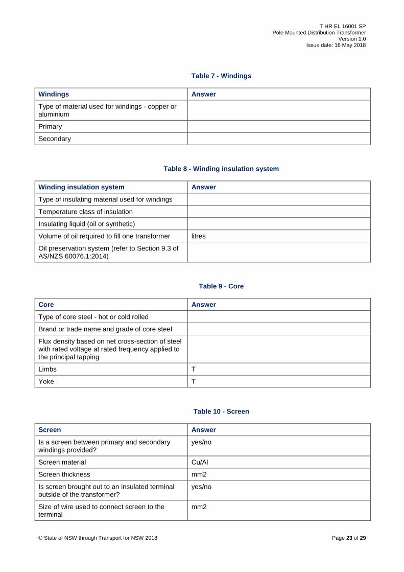
Table 7 - Windings
Windings Answer
Type of material used for windings - copper or aluminium
Primary
Secondary
Table 8 - Winding insulation system
Winding insulation system Answer
Type of insulating material used for windings
Temperature class of insulation
Insulating liquid (oil or synthetic)
Volume of oil required to fill one transformer litres
Oil preservation system (refer to Section 9.3 of AS/NZS 60076.1:2014)
Table 9 - Core
Core Answer
Type of core steel - hot or cold rolled
Brand or trade name and grade of core steel
Flux density based on net cross-section of steel with rated voltage at rated frequency applied to the principal tapping
Limbs T
Yoke T
Table 10 - Screen
Screen Answer
Is a screen between primary and secondary windings provided?
yes/no
Screen material Cu/Al
Screen thickness mm2
Is screen brought out to an insulated terminal outside of the transformer?
yes/no
Size of wire used to connect screen to the terminal
mm2
© State of NSW through Transport for NSW 2018 Page 23 of 29

T HR EL 16001 SP Pole Mounted Distribution Transformer
Version 1.0 Issue date: 16 May 2018
Table 11 - Tank
Tank Answer
Protective treatment applied to the tank
Internal surfaces
External surfaces
Table 12 - Bushings
Bushings Answer
Voltage withstand test which the bushings will withstand without puncture or flashover in accordance with Section 7.2.1 and Table 7 of AS/NZS 60137:2008
Table 13 – 11 kV or 33 kV bushing details
11 kV or 33 kV bushing details Answer
Bushing type
Lightning impulse withstand voltage kVp
Power frequency withstand voltage kVrms
Exposed bushings
Is heat shrink or other insulating covers required to achieve these values?
yes / no
If so, is the necessary material provided with the transformer?
yes / no
Table 14 – 433 V or 250 V or 125 V bushing details
433 V or 250 V or 125 V bushing details Answer
Bushing type
Lightning impulse withstand voltage (if required) kVp
Power frequency withstand voltage kVrms
Bushings, minimum clearance in air:
© State of NSW through Transport for NSW 2018 Page 24 of 29

T HR EL 16001 SP Pole Mounted Distribution Transformer
Version 1.0 Issue date: 16 May 2018
Table 15 - 433 V or 250 V or 125 V bushing details – Bushings, minimum clearance in air
Primary Secondary
between phases mm mm
phase to earth mm mm
Table 16 - Transformer dimensions
Transformer dimensions Answer
Depth (dimension on axis parallel to supporting cross arm)
mm
Width (dimension on axis perpendicular to supporting cross arm)
mm
Height mm
Mass of windings only kg
Mass of transformer core and windings only kg
Mass of transformer complete with oil kg
Table 17 - Insulating oil
Insulating Oil Answer
Volume of oil required to fill transformer, complete
Litres
Oil brand and type
Table 18 - RAMS
RAMS Answer
Mean time between failures
Mean time to repair
Availability or uptime
Failure modes
Critical components and spare parts
© State of NSW through Transport for NSW 2018 Page 25 of 29

T HR EL 16001 SP Pole Mounted Distribution Transformer
Version 1.0 Issue date: 16 May 2018
Table 19 - General
General Answer
Other relevant information
Table 20 - Departures from Specification
Departures from Specification Answer
Are there any departures from the requirements of this document?
yes / no
Departures from the requirements of this specification shall be detailed
D.2. Drawings and information to be submitted with the tender In addition to the technical schedule, the following information shall also be submitted with the
tender:
• Outline drawings: Fully dimensioned outline drawings showing all fittings and terminal
arrangements. The general arrangements and layouts shall be adhered to in the final
design unless written approval is obtained from TfNSW.
• Core material characteristics: Typical curves of flux density versus ampere turns per metre
for the core material.
• Core information: Detailed description of the core type, methods of making joints, insulation
between laminations, treatment of edges, core bolt insulation and method for minimising
hot spots in limbs. Include details of the proposed method for verifying core hot spot
temperature and method for how the core is earthed.
• Other information: Any other information considered necessary by the manufacturer.
• Features of the transformer design: Provide details of the transformer design. This should
include a description of the following:
© State of NSW through Transport for NSW 2018 Page 26 of 29

T HR EL 16001 SP Pole Mounted Distribution Transformer
Version 1.0 Issue date: 16 May 2018
o the overall transformer design
o the method for electrically, thermally and structurally modelling the design
o lessons learnt from previous similar designs and how this has been addressed in this
design
o quality processes during design and manufacture to ensure the design will meet the
TfNSW and appropriate Australian and international standards and how the
manufacture of the transformer will be in accordance with the design
• Departures from standard: Are there any departures from the requirements of this
specification? If there are departures, include details on a separate sheet.
• Special delivery requirements: Any special requirements that are envisaged for the safe
delivery of the transformer to the specified site shall be stated at tender stage. These costs
shall be provided separately at the tender stage.
© State of NSW through Transport for NSW 2018 Page 27 of 29

T HR EL 16001 SP Pole Mounted Distribution Transformer
Version 1.0 Issue date: 16 May 2018
Appendix E Integrated system support requirements
The transformer manufacturer shall establish and provide the information required to operate
and maintain the equipment throughout its operational life, in a cost effective manner and to a
level that is consistent with the planned operational performance and usage of the transformer.
This includes the following:
• specifying maintenance requirements
• spares support
• operations and maintenance manuals
• support equipment and tooling
E.1. Equipment supplier deliverable The integrated support requirements are a significant deliverable in the procurement of new
transformers. Manuals, training, documentation and other support deliverables shall be in
accordance with T HR EL 00002 PR Electrical Power Equipment – Integrated Support
Requirements.
E.2. Operation and maintenance manual An operation and maintenance manual shall be provided for the equipment in accordance with
the requirements of T HR EL 00002 PR. The requirements for the scope of the operation and
maintenance manual are as detailed in T HR EL 00002 PR.
All operation instructions and associated descriptions of equipment shall be accompanied by
colour photos of the actual equipment installed on the transformer that is being described.
© State of NSW through Transport for NSW 2018 Page 28 of 29
T HR EL 16001 SP Pole Mounted Distribution Transformer
Version 1.0 Issue date: 16 May 2018
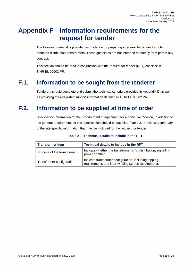
Appendix F Information requirements for the request for tender
The following material is provided as guidance for preparing a request for tender for pole
mounted distribution transformers. These guidelines are not intended to directly form part of any
contract.
This section should be read in conjunction with the request for tender (RFT) checklist in
T HR EL 00002 PR.
F.1. Information to be sought from the tenderer Tenderers should complete and submit the technical schedule provided in Appendix D as well
as providing the integrated support information detailed in T HR EL 00002 PR.
F.2. Information to be supplied at time of order Site-specific information for the procurement of equipment for a particular location, in addition to
the general requirements of this specification should be supplied. Table 21 provides a summary
of the site-specific information that may be included for the request for tender.
Table 21 - Technical details to include in the RFT
Transformer item Technical details to include in the RFT
Purpose of the transformer Indicate whether the transformer is for distribution, signalling power or other
Transformer configuration Indicate transformer configuration, including tapping requirements and inter-winding screen requirements
© State of NSW through Transport for NSW 2018 Page 29 of 29