Embed Size (px)
Citation preview
PolarPrep 2000 Cryo Transfer System
Operating Manual
Document Number OM-PP2000
Issue 1.2 (07/09)

PolarPrep 2000 Cryo Transfer System 2 Issue 1.2
For technical and applications advice plus our on-line shop for spares and consumable parts visit www.quorumtech.com

Quorum Technologies Ltd. Company No. 4273003. Registered offices 30/34 North Street Hailsham, East Sussex, England, BN27 1DW
Quorum Technologies Ltd is the owner and manufacture of the range of EM preparation equipment. 2 Acorn House The Broyle Ringmer East Sussex BN8 5NN Tel: ++44(0) 1273 815340 UK Fax: ++44(0) 1273 813439 Email : [email protected] http:///www.quorumtech.com For further information regarding any of the other products designed and manufactured by Quorum Technologies, contact your local representative or directly to Quorum Technologies at the address above.
• Carbon and Sputter Coaters
• Plasma Reactor for ashing and etching
• High Vacuum Bench Top Evaporators
• Cryo Transfer Systems
• Critical Point Dryers
• Service and Spares
For technical and applications advice plus our on-line shop for spares and consumable parts visit www.quorumtech.com
Disclaimer The components and packages described in this document are mutually compatible and guaranteed to meet or exceed the published performance specifications. However, no performance guarantees can be given in circumstances where these component packages are used in conjunction with equipment supplied by companies other than Quorum Technologies.

OM-PP2000
PolarPrep 2000 Cryo Transfer System 4 Issue 1.2

OM-PP2000
Issue 1.2 5 PolarPrep 2000 Cryo Transfer System
Table of contents 1 Health and Safety ......................................................................................................................................................... 9
1.1 Control of Substances Hazardous to Health (COSHH) .......................................................................................... 9 1.2 Safety Policy .......................................................................................................................................................... 9 1.3 Conformity ............................................................................................................................................................ 9
2 Servicing ...................................................................................................................................................................... 11 2.1 Disclaimer ........................................................................................................................................................... 11 2.2 Operators and Service Engineers ........................................................................................................................ 11 2.3 Hazard Signals and Signs ..................................................................................................................................... 11 2.4 Hazard Signal Words ........................................................................................................................................... 11 2.5 Hazard Labels used on Equipment...................................................................................................................... 11 2.6 Hazard Warning Labels used in Equipment Manuals ......................................................................................... 12 2.7 Instrument Functionality Signs ........................................................................................................................... 12 2.8 Serious Damage to Instruments ......................................................................................................................... 12 2.9 Hazard to Operator ............................................................................................................................................. 12 2.10 Risk Analysis ........................................................................................................................................................ 13 2.11 Personal Operational Risks ................................................................................................................................. 13 2.12 Hazardous Materials ........................................................................................................................................... 13 2.13 Good Working Practices ..................................................................................................................................... 14 2.14 PolarPrep 2000 Specific Safety Hazards ............................................................................................................. 15 2.15 Gases ................................................................................................................................................................... 15
3 Introduction ................................................................................................................................................................ 17 3.1 Return of Goods .................................................................................................................................................. 17 3.2 Returns Procedure .............................................................................................................................................. 17
4 Description .................................................................................................................................................................. 19 4.1 Equipment .......................................................................................................................................................... 19 4.2 Optional Components ......................................................................................................................................... 19 4.3 Consumables ....................................................................................................................................................... 20 4.4 Vacuum Pumping Accessory ............................................................................................................................... 20
5 Overview ..................................................................................................................................................................... 21 5.1 Technical Specification ....................................................................................................................................... 21 5.2 PP2000/PP2000T Preparation Chamber Specification ....................................................................................... 21 5.3 PP2000/PP2000T SEM Dewar and Stage Specification ...................................................................................... 21 5.4 PP7480 Control Unit Specification ...................................................................................................................... 22 5.5 PP7482 Turbo Control Unit Specification ........................................................................................................... 22 5.6 PP7483 Gas Control Unit Specification ............................................................................................................... 22 5.7 Weights and Sizes ............................................................................................................................................... 22
6 Physical Description .................................................................................................................................................... 23 6.1 Preparation Chamber ......................................................................................................................................... 24 6.2 PP7409 Transfer Device ...................................................................................................................................... 25 6.3 Cryogenic Stage .................................................................................................................................................. 25 6.4 Sample Preparation ............................................................................................................................................ 25 6.5 SEM Stage and Dewar ......................................................................................................................................... 26 6.6 Electronic Units ................................................................................................................................................... 27 6.7 PP7480 Control Unit ........................................................................................................................................... 27 6.8 PP7482 Turbo Control Unit ................................................................................................................................. 30 6.9 PP7483 Gas Control Unit .................................................................................................................................... 30 6.10 Instrument Trolley .............................................................................................................................................. 31 6.11 Liquid Nitrogen Slush Chamber .......................................................................................................................... 31 6.12 Anti‐vibration Pumping Block ............................................................................................................................. 32 6.13 PP2000 Anti‐vibration Pumping Block ................................................................................................................ 32 6.14 PP2000T Turbo Anti‐vibration Pumping Block .................................................................................................... 32
7 Installation .................................................................................................................................................................. 35 7.1 Unpacking Checklist ............................................................................................................................................ 35 7.2 Preparation ......................................................................................................................................................... 35 7.3 PP2000/PP2000T Installation ............................................................................................................................. 35 7.4 Hardware ............................................................................................................................................................ 36
OM-PP2000
PolarPrep 2000 Cryo Transfer System 6 Issue 1.2
7.5 Connecting the PTFE tubing ............................................................................................................................... 37 7.6 Connections ........................................................................................................................................................ 39 7.7 Alignment ........................................................................................................................................................... 43
8 Operation ................................................................................................................................................................... 45 8.1 Initial Preparation ............................................................................................................................................... 45 8.2 Preparation of LN2 ‘Slush’ and Sample Freezing ................................................................................................ 45
9 Specimen Operations ................................................................................................................................................. 47 9.1 Specimen Transfer .............................................................................................................................................. 47 9.2 Specimen Fracturing ........................................................................................................................................... 47 9.3 Specimen Etching ............................................................................................................................................... 47 9.4 Specimen Coating (Sputtering) ........................................................................................................................... 48 9.5 Specimen Coating (Evaporation) ........................................................................................................................ 48 9.6 Specimen Preparation ........................................................................................................................................ 49 9.7 Surface Mounting ............................................................................................................................................... 50 9.8 Edge Mounting ................................................................................................................................................... 50 9.9 Filter Mounting ................................................................................................................................................... 50 9.10 Hole Mounting .................................................................................................................................................... 51 9.11 Film Emulsion Mounting..................................................................................................................................... 51 9.12 Liquid Film Mounting.......................................................................................................................................... 51 9.13 Rivet Mounting ................................................................................................................................................... 51 9.14 Performance Rates ............................................................................................................................................. 52
10 Short Form Operating Instructions ........................................................................................................................ 53 10.1 Set‐up ................................................................................................................................................................. 53 10.2 Sample Transfer .................................................................................................................................................. 53 10.3 Sputter Coating................................................................................................................................................... 54
11 Maintenance .......................................................................................................................................................... 55 11.1 Maintenance ‐ General ....................................................................................................................................... 55 11.2 Routine Maintenance ......................................................................................................................................... 55 11.3 Daily Maintenance .............................................................................................................................................. 55 11.4 Weekly Maintenance ......................................................................................................................................... 56 11.5 Periodical Maintenance ...................................................................................................................................... 56
12 PP7480 Control Unit Settings ................................................................................................................................. 57 12.1 Control PCB Settings ........................................................................................................................................... 57 12.2 Preparation Chamber Settings ........................................................................................................................... 57 12.3 SEM Chamber Settings ....................................................................................................................................... 57 12.4 Circuit Diagrams ................................................................................................................................................. 58 12.5 Spare Parts ......................................................................................................................................................... 60
13 Fault Finding ........................................................................................................................................................... 61 14 Appendix I ‐ Dual slusher option ............................................................................................................................ 63
14.1 Introduction ........................................................................................................................................................ 63 14.2 Using the dual slusher ........................................................................................................................................ 63 14.3 Advantages of the dual slusher system .............................................................................................................. 65 14.4 Special specimen shuttles .................................................................................................................................. 65 14.5 A more detailed description ............................................................................................................................... 66
15 Appendix II – CHE2000 option ................................................................................................................................ 69 15.1 Overview............................................................................................................................................................. 69 15.1.1 12 litre capacity SEM cooling dewar. ............................................................................................................. 69 15.1.2 Features and advantages: .............................................................................................................................. 69 15.2 Operation ........................................................................................................................................................... 69 15.2.1 Cooldown ....................................................................................................................................................... 69 15.2.2 Warm‐up ........................................................................................................................................................ 70
16 Agents ..................................................................................................................................................................... 71 17 Index ....................................................................................................................................................................... 73
OM-PP2000
Issue 1.2 7 PolarPrep 2000 Cryo Transfer System
List of tables Table 1 - Hazard Warning Symbols ................................................................................................ 11
Table 2 - International Warning Symbols ........................................................................................ 12
Table 3 - Typical functionality warning sign as shown in this Manual ............................................. 12
Table 4 - Typical hazard warning sign as shown in this Manual .................................................... 12
Table 5 - Typical Warning as shown in this Manual ........................................................................ 12
Table 6 - Personal Operational Risks ............................................................................................. 13
Table 7 - Table of Sizes and Weights ............................................................................................. 22
Table 8 - PP7480 Front Panel Control Descriptions ....................................................................... 29
Table 9 – Control PCB Settings ...................................................................................................... 57
Table 10 – Prep Chamber Cal Temperature Controller Settings .................................................... 57
Table 11 – Prep Chamber Cal Temperature Controller Settings .................................................... 57
Table 12 - Spare Parts for the PP2000 ........................................................................................... 60
List of figures Figure 1 - PP2000/PP2000T Preparation Chamber (right hand) .................................................... 24
Figure 2 - Transfer Device – Closed and Open .............................................................................. 25
Figure 3 - SEM Stage and Dewar ................................................................................................... 26
Figure 4 - Electronic Units ............................................................................................................... 27
Figure 5 - PP7480 Control Unit, Front Panel Controls .................................................................... 28
Figure 6 - PP7482 Turbo Control Unit Front Panel ......................................................................... 30
Figure 7 - PP7483 Gas Control Unit ............................................................................................... 31
Figure 8 - Liquid Nitrogen Slusher .................................................................................................. 31
Figure 9 – Anti-vibration Pumping Block ......................................................................................... 32
Figure 10 – Turbo Anti-vibration Pumping Block ............................................................................ 33
Figure 11 - Typical PP2000 Installation .......................................................................................... 36
Figure 12 - Tube flaring tool ............................................................................................................ 37
Figure 13 - Polar Prep 2000/2000T SEM Stage Connections ........................................................ 38
Figure 14 – Polar Prep 2000/2000T “Slush” Chamber Connections .............................................. 38
Figure 15 – Polar Prep 2000/2000T Vacuum Tubing Layout ......................................................... 39
Figure 16 – Polar Prep 2000/2000T Cable Connections ............................................................... 41
Figure 17 – Polar Prep 2000/2000T Dewar Gas Connections ....................................................... 42
Figure 18 – Leaf Sample Preparation ............................................................................................. 50
Figure 19 - Edge Mount Preparation ............................................................................................... 50
Figure 20 – Filter Mounting Preparation .......................................................................................... 50
Figure 21 – Hole Mount Preparation ............................................................................................... 51
Figure 22 - Film Mount Preparation ................................................................................................ 51
Figure 23 - Liquid Preparation ......................................................................................................... 51
Figure 24 - Rivet Mounting Preparation ......................................................................................... 51
Figure 25 – Typical Cooling Rates .................................................................................................. 52
Figure 26 - Typical Sputtering Rates ............................................................................................... 52
OM-PP2000
PolarPrep 2000 Cryo Transfer System 8 Issue 1.2
Figure 27 – PP7480 Control Unit Circuit Diagram .......................................................................... 58
Figure 28 – PP7482 Turbo Control Unit Circuit Diagram ............................................................... 59
Figure 29 - Overview of the dual slushing system .......................................................................... 63
Figure 30 - Dual slushing pot .......................................................................................................... 63
Figure 31 – Dovetail support horizontal .......................................................................................... 64
Figure 32 - Dovetail support vertical................................................................................................ 64
Figure 33 - Specimen shuttle inserted ............................................................................................ 66
Figure 34 - Fitting vacuum collar ..................................................................................................... 66
Figure 35 - Tilting 66
Figure 36 -Mounting the specimen .................................................................................................. 66
Figure 37 - Transfer device fitted .................................................................................................... 66
Figure 38 - Collar fitted 66
Figure 39 - vacuum transferred in to the PP2000 preparation chamber in the normal way ........... 67
Figure 40 - The main chamber is vented and the specimen shuttle is… ........................................ 67
Figure 41 - The vacuum chamber is evacuated (pumped) and the specimen shuttle retracted into the inner vacuum chamber of the transfer device. ................................................................................ 67
Figure 42 - On column dewar .......................................................................................................... 69
Figure 43 - CHE 2000 69
OM-PP2000
Issue 1.2 9 PolarPrep 2000 Cryo Transfer System
1 Health and Safety Safety is very important when using any instrumentation and this chapter should be read by all users of our equipment.
This section of the Manual applies to all surface analysis and sample preparation equipment supplied by Quorum Technologies Polaron range of products, not just the particular instrument for which the manual refers.
Included in this chapter are details on warning notations, good working practices and information on European Community (EC) legislation regarding “Control of Substances Hazardous to Health” (COSHH) and risk analysis.
1.1 Control of Substances Hazardous to Health (COSHH)
The E.C. legislation regarding the “Control of Substances Hazardous to Health” requires Quorum Technologies to monitor and assess every substance entering or leaving their premises. Consequently any returned goods of whatever nature must be accompanied by a declaration form available from Quorum Technologies, reference number HSC100. Without this declaration Quorum Technologies reserves the right not to handle the substance/item. Also in accordance with E.C. regulations we will supply on request hazard data sheets for substances used in our instruments.
1.2 Safety Policy
This section contains important information relating to all health and safety aspects of the equipment. As such it should be read, and understood, by all personnel using the instrument whether as an operator or in a service capacity.
Quorum Technologies is committed to providing a safe working environment for its employees and those that use its’ equipment and conducts its business responsibly, and in a manner designed to protect the health and safety of its customers, employees and the public at large. It also seeks to minimise any adverse effects that its activities may have on the environment.
Quorum Technologies regularly reviews its operations to make environmental, health and safety improvements in line with UK and European Community legislation.
Quorum Technologies cannot be held responsible for any damage, injury or consequential loss arising from the use of its equipment for any other purposes, or any unauthorised modifications made to the equipment.
All service work carried out on the equipment should only be undertaken by suitably qualified personnel. Quorum Technologies is not liable for any damage, injury or consequential loss resulting from servicing by unqualified personnel. Quorum Technologies will also not be liable for damage, injury or consequential loss resulting from incorrect operation of the instrument or modification of the instrument.
1.3 Conformity
This instrument is supplied in a form that complies with the protection requirements of the EC Electromagnetic Compatibility Directive 89/336/EEC and the essential health and safety requirements of the low voltage directive 72/23/EEC both as amended by 92/31/EEC. Any modifications to the equipment, including electronics or cable layout may affect the compliance with these directives.

OM-PP2000
PolarPrep 2000 Cryo Transfer System 10 Issue 1.2
OM-PP2000
Issue 1.2 11 PolarPrep 2000 Cryo Transfer System
2 Servicing 2.1 Disclaimer
All service work on the equipment should be carried out by qualified personnel. Quorum Technologies cannot be liable for damage, injury or consequential loss resulting from servicing from unqualified personnel. Quorum Technologies will also not be liable for damage, injury or consequential loss resulting from incorrect operation of the instrument or modification of the instrument.
2.2 Operators and Service Engineers
Beyond regular maintenance, a normal operator of the equipment will not be trained in or qualified for service work on the equipment and may cause a hazard to themselves or others if such work is attempted. Operators should therefore restrict themselves to the normal operation of the equipment and not by removing covers from the electronic equipment or dismantling of the instruments.
Service Engineers who are suitably trained to assess and isolate electrical, mechanical and vacuum hazards should be the only personnel who access the equipment.
2.3 Hazard Signals and Signs
2.3.1 Hazard Signal Words
The standard three hazard signal words are defined as follows:
DANGER - imminently hazardous situation or unsafe practice that, if not avoided, will result in death or severe injury.
WARNING - potentially hazardous situation or unsafe practice that, if not avoided, could result in death or severe injury.
CAUTION - potentially hazardous situation or unsafe practice that, if not avoided, may result in minor or moderate injury or damage to equipment.
2.3.2 Hazard Labels used on Equipment
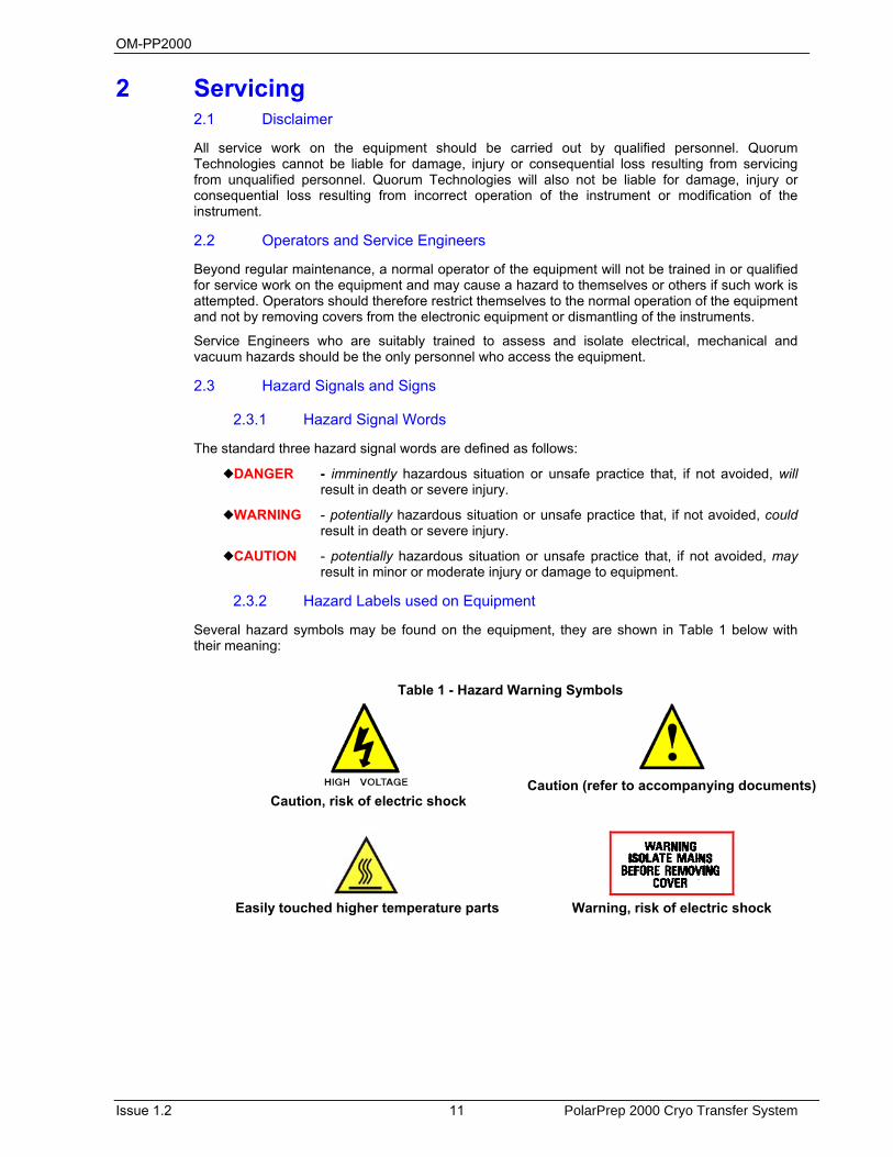
Several hazard symbols may be found on the equipment, they are shown in Table 1 below with their meaning:
Table 1 - Hazard Warning Symbols
Caution, risk of electric shock
Caution (refer to accompanying documents)
Easily touched higher temperature parts
Warning, risk of electric shock
OM-PP2000
PolarPrep 2000 Cryo Transfer System 12 Issue 1.2
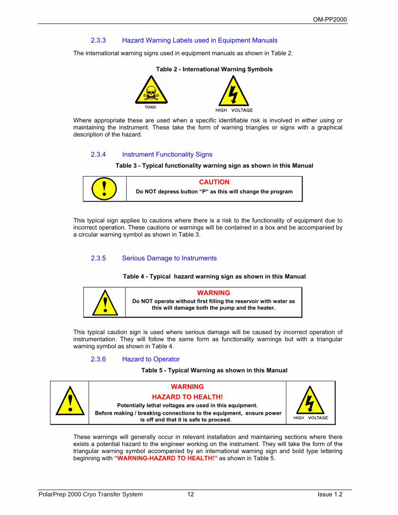
2.3.3 Hazard Warning Labels used in Equipment Manuals
The international warning signs used in equipment manuals as shown in Table 2.
Table 2 - International Warning Symbols
Where appropriate these are used when a specific identifiable risk is involved in either using or maintaining the instrument. These take the form of warning triangles or signs with a graphical description of the hazard.
2.3.4 Instrument Functionality Signs Table 3 - Typical functionality warning sign as shown in this Manual
CAUTION Do NOT depress button “P” as this will change the program
This typical sign applies to cautions where there is a risk to the functionality of equipment due to incorrect operation. These cautions or warnings will be contained in a box and be accompanied by a circular warning symbol as shown in Table 3.
2.3.5 Serious Damage to Instruments
Table 4 - Typical hazard warning sign as shown in this Manual
WARNING Do NOT operate without first filling the reservoir with water as
this will damage both the pump and the heater.
This typical caution sign is used where serious damage will be caused by incorrect operation of instrumentation. They will follow the same form as functionality warnings but with a triangular warning symbol as shown in Table 4.
2.3.6 Hazard to Operator Table 5 - Typical Warning as shown in this Manual
WARNING HAZARD TO HEALTH!
Potentially lethal voltages are used in this equipment. Before making / breaking connections to the equipment, ensure power
is off and that it is safe to proceed.
These warnings will generally occur in relevant installation and maintaining sections where there exists a potential hazard to the engineer working on the instrument. They will take the form of the triangular warning symbol accompanied by an international warning sign and bold type lettering beginning with “WARNING-HAZARD TO HEALTH!” as shown in Table 5.

OM-PP2000
Issue 1.2 13 PolarPrep 2000 Cryo Transfer System
2.4 Risk Analysis
2.4.1 Personal Operational Risks
The following is a list of tasks carried out by both the operator and service engineer where recognised risks have been observed, listed is the personnel protection equipment (PPE) which is suggested for use for various tasks on any surface analysis equipment and systems.
Table 6 - Personal Operational Risks
Task Carried out by Nature of Hazard Recommended PPECleaning of parts / samples with isopropanol (IPA)
Operator / Service engineer
Splash hazard to eyes, drying of skin
Protective goggles, protective gloves.
Use of Liquid Nitrogen in sample cooling etc.
Operator / Service engineer
Burn risk. Axphyxiation risk.
Thermally protective gloves and goggles should be worn. Ensure adquate ventilation.
Lifting of Heavy Items
Service engineer Dropping on foot. Protective footware.
2.4.2 Hazardous Materials
Isopropanol (IPA
For certain service tasks isopropanol is suggested for cleaning components before use in the vacuum system. It should be noted that isopropanol is a flammable liquid and as such should not be used on hot surfaces. In addition it is recommended that protective gloves are worn when using isopropanol.
Liquid Nitrogen
Only operators with experience in the safe handling of liquid nitrogen should use the equipment under these conditions. Thermally insulated gloves and goggles should be worn at all times when handling and using liquid nitrogen.
Compressed Air
Compressed air can be a potential hazard if handled inappropriately. A compressed air line may be fed from some instruments to the customers supply, and the customer should ensure that this and any other service pipes and cables are maintained in good condition.
Nitrogen, Argon and Helium Gas Supplies
Instruments may use nitrogen, argon or helium gas supplies for their operation, the customer is responsible for maintaining the supply to the instrument. This supply should be regulated and kept to the lowest pressure and flow rate as is practical to minimise the effects of any leaks.
Hazardous Gases
Quorum Technologies has no control over the gases used within the system. It is therefore viewed as the customers’ responsibility to assess the hazards involved and take appropriate precautions when using explosive, toxic or corrosive gases or gases which may result in hazardous products as a result of a chemical reaction.
OM-PP2000
PolarPrep 2000 Cryo Transfer System 14 Issue 1.2
2.5 Good Working Practices
It is essential that good hygienic working practices are adopted at all times especially in an ultra high vacuum or cleanroom environment and are generally of the “common sense” type. Some simple good practice rules are:
If in doubt don't.
If in doubt ask.
When handling solvents wear face mask, gloves, apron and work only in a well ventilated area.
Mop up any spillages immediately.
When handling or decanting mineral oils wear protective clothing.
Aerosols of mineral oils, such as that produced by gas ballasting, can prove to be hazardous and an external exhaust is recommended.
Before attempting to service electrical apparatus, isolate from the mains.
Treat all unknown substances as hazardous.
Dispose of substances in an appropriate manner.
Use the correct tool for the job.
Keep a straight back and bend from the knees when lifting heavy objects.
Wear protective clothing when using liquid nitrogen.
Affix pressurised gas cylinders firmly to walls or racks. Use the correct regulating valves on gas cylinders and always transport cylinders using the appropriate specialist trolley.
Obey safety regulations regarding lifts, hoists and machine tools.
Always make sure you understand a procedure well before attempting it for the first time.
OM-PP2000
Issue 1.2 15 PolarPrep 2000 Cryo Transfer System
2.6 PolarPrep 2000 Specific Safety Hazards
The following Safety Hazards are specific to the PolarPrep 2000 (PP2000) Cryo Transfer System.
2.6.1 Gases
Nitrogen and Argon Gas Supplies
This instrument uses nitrogen and argon gas supplies for operation; the customer is responsible for maintaining the supply to the instrument. This supply should be regulated and kept to the lowest pressure and flow rate as is practical to minimise the effects of any leaks.
Quorum Technologies has no control over the gases used within the system. It is therefore viewed as the customers’ responsibility to assess the hazards involved and take appropriate precautions when using explosive, toxic or corrosive gases or gases which may result in hazardous products as a result of a chemical reaction.
Extreme care to be used when filling the slusher vessel with liquid nitrogen, follow your companies standard Health and Safety instruction when using this liquid gas.

OM-PP2000
PolarPrep 2000 Cryo Transfer System 16 Issue 1.2

OM-PP2000
Issue 1.2 17 PolarPrep 2000 Cryo Transfer System
3 Introduction This manual is intended for all users of the PP2000/PP2000T Cryo Systems manufactured by Quorum Technologies from the POLARON range and provides information on the installation, operation and maintenance of the instrument.
Please note that the servicing and maintenance procedures should only be carried out by qualified service personnel and it is essential that all users should read the Health and Safety section of this manual.
3.1 Return of Goods
If goods are to be returned to Quorum Technologies for repair or servicing the customer should contact their local distributor or the factory direct before shipment. A "Returns Authorisation Number" should be obtained in advance of any shipment. This number is to be clearly marked on the outside of the shipment. Complete a “Returned Equipment Report” form, number SP-106 with as much detail as possible and return with the goods. All returned goods are to be accompanied by a completed "Returned Goods Health and Safety Clearance" form HSC-100 attached to the outside of the package (to be accessible without opening the package) and a copy of the forms should be faxed in advance to the factory. When goods are to be returned under warranty refer to the “Warranty Claim, Repair and Returns Procedure” form number SP-105. Copies of all these three forms can be found in the documentation pack supplied with the instrument or direct from Quorum Technologies, the details can be found on page two of this document or on the Quorum web pages. 3.2 Returns Procedure Warranty Claim
Electronic and basic servicing capabilities exist at most in-country appointed agents, however all components are sold with a return to factory warranty (unless otherwise stated) which covers failure during the first 12 months after delivery. This is extended by a further 2 years if the warranty form is returned to Quorum Technologies. Returns must be sent carriage paid, Quorum Technologies will cover the return carriage costs. This covers defects which arise as a result of a failure in design or manufacturing. It is a condition of warranty that equipment must be used in accordance with the manufacturers’ instructions and not have been subjected to misuse. This warranty does not cover consumable items such as sputter coating targets and carbon evaporation material. To make a claim under the terms of this warranty provision contact the Customer Service Department at your local Quorum Technologies Representative in the first instance.
Chargeable Repairs Always contact your in-country Quorum Technologies Representative in the first instance. They will be pleased to assist you and will be able to provide an estimate of repair costs; many offer local repair facilities. For routine repairs, where down-time is not critical, the target standard return time at Quorum Technologies is 20 working days.
Returns All returns to Quorum Technologies require the following procedure to be followed: 1. Contact the local Quorum Technologies Representative and request a Returns Authorisation
Number. 2. Complete a Returned Goods Health and Safety form and returned equipment fault report form. 3. Attach a copy of the completed forms to the outside of the package with the usual shipping
documents. Packaging and Carriage
All goods shipped to the factory must be sealed inside a clean plastic bag and packed in a suitable carton. If the original packaging is not available Quorum Technologies should be contacted for advice. Quorum Technologies will not be responsible for damage resulting from inadequate returns packaging or contamination of delicate structures by stray particles under any circumstances. All non-warranty goods returned to the factory must be sent carriage pre-paid, (Free Domicile). They will be returned carriage forward (Ex-Works).

OM-PP2000
PolarPrep 2000 Cryo Transfer System 18 Issue 1.2
OM-PP2000
Issue 1.2 19 PolarPrep 2000 Cryo Transfer System
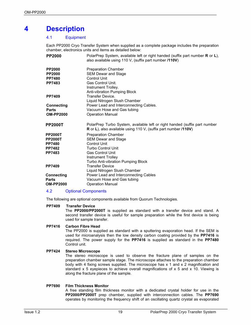
4 Description 4.1 Equipment
Each PP2000 Cryo Transfer System when supplied as a complete package includes the preparation chamber, electronics units and items as detailed below: PP2000 PolarPrep System, available left or right handed (suffix part number R or L),
also available using 110 V, (suffix part number /110V)
PP2000 Preparation Chamber PP2000 SEM Dewar and Stage PP7480 Control Unit PP7483 Gas Control Unit.
Instrument Trolley. Anti-vibration Pumping Block
PP7409 Transfer Device. Liquid Nitrogen Slush Chamber
Connecting Parts
Power Lead and Interconnecting Cables. Vacuum Hose and Gas tubing
OM-PP2000 Operation Manual
PP2000T PolarPrep Turbo System, available left or right handed (suffix part number R or L), also available using 110 V, (suffix part number /110V)
PP2000T Preparation Chamber PP2000T SEM Dewar and Stage PP7480 Control Unit PP7482 Turbo Control Unit PP7483 Gas Control Unit
Instrument Trolley Turbo Anti-vibration Pumping Block
PP7409 Transfer Device Liquid Nitrogen Slush Chamber
Connecting Parts
Power Lead and Interconnecting Cables Vacuum Hose and Gas tubing
OM-PP2000 Operation Manual
4.2 Optional Components
The following are optional components available from Quorum Technologies.
PP7409 Transfer Device The PP2000/PP2000T is supplied as standard with a transfer device and stand. A second transfer device is useful for sample preparation while the first device is being used for sample transfer.
PP7416 Carbon Fibre Head The PP2000 is supplied as standard with a sputtering evaporation head. If the SEM is used for microanalysis then the low density carbon coating provided by the PP7416 is required. The power supply for the PP7416 is supplied as standard in the PP7480 Control unit.
PP7424 Stereo Microscope The stereo microscope is used to observe the fracture plane of samples on the preparation chamber sample stage. The microscope attaches to the preparation chamber body with 4 fixing screws supplied. The microscope has x 1 and x 2 magnification and standard x 5 eyepieces to achieve overall magnifications of x 5 and x 10. Viewing is along the fracture plane of the sample.
PP7690 Film Thickness Monitor A free standing film thickness monitor with a dedicated crystal holder for use in the PP2000/PP2000T prep chamber, supplied with interconnection cables. The PP7690 operates by monitoring the frequency shift of an oscillating quartz crystal as evaporated
OM-PP2000
PolarPrep 2000 Cryo Transfer System 20 Issue 1.2
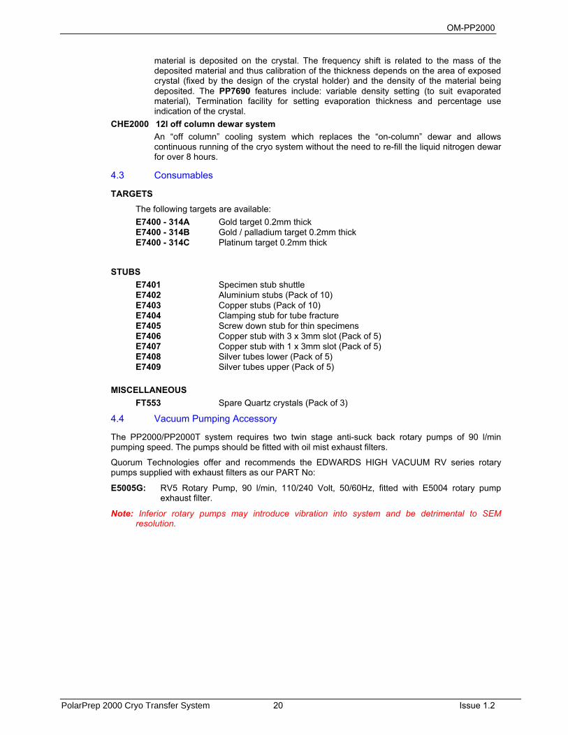
material is deposited on the crystal. The frequency shift is related to the mass of the deposited material and thus calibration of the thickness depends on the area of exposed crystal (fixed by the design of the crystal holder) and the density of the material being deposited. The PP7690 features include: variable density setting (to suit evaporated material), Termination facility for setting evaporation thickness and percentage use indication of the crystal.
CHE2000 12l off column dewar system An “off column” cooling system which replaces the “on-column” dewar and allows continuous running of the cryo system without the need to re-fill the liquid nitrogen dewar for over 8 hours.
4.3 Consumables TARGETS
The following targets are available: E7400 - 314A Gold target 0.2mm thick E7400 - 314B Gold / palladium target 0.2mm thick E7400 - 314C Platinum target 0.2mm thick
STUBS
E7401 Specimen stub shuttle E7402 Aluminium stubs (Pack of 10) E7403 Copper stubs (Pack of 10) E7404 Clamping stub for tube fracture E7405 Screw down stub for thin specimens E7406 Copper stub with 3 x 3mm slot (Pack of 5) E7407 Copper stub with 1 x 3mm slot (Pack of 5) E7408 Silver tubes lower (Pack of 5) E7409 Silver tubes upper (Pack of 5)
MISCELLANEOUS FT553 Spare Quartz crystals (Pack of 3)
4.4 Vacuum Pumping Accessory
The PP2000/PP2000T system requires two twin stage anti-suck back rotary pumps of 90 l/min pumping speed. The pumps should be fitted with oil mist exhaust filters.
Quorum Technologies offer and recommends the EDWARDS HIGH VACUUM RV series rotary pumps supplied with exhaust filters as our PART No:
E5005G: RV5 Rotary Pump, 90 l/min, 110/240 Volt, 50/60Hz, fitted with E5004 rotary pump exhaust filter.
Note: Inferior rotary pumps may introduce vibration into system and be detrimental to SEM resolution.
OM-PP2000
Issue 1.2 21 PolarPrep 2000 Cryo Transfer System
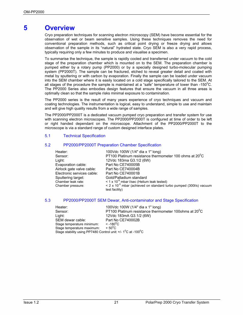
5 Overview Cryo preparation techniques for scanning electron microscopy (SEM) have become essential for the observation of wet or beam sensitive samples. Using these techniques removes the need for conventional preparation methods, such as critical point drying or freeze drying and allows observation of the sample in its “natural” hydrated state. Cryo SEM is also a very rapid process, typically requiring only a few minutes to produce and visualise a specimen.
To summarise the technique, the sample is rapidly cooled and transferred under vacuum to the cold stage of the preparation chamber which is mounted on to the SEM. The preparation chamber is pumped either by a rotary pump (PP2000) or by a specially designed turbo-molecular pumping system (PP2000T). The sample can be fractured, etched to reveal greater detail and coated with metal by sputtering or with carbon by evaporation. Finally the sample can be loaded under vacuum into the SEM chamber where it is easily located on a cold stage specifically tailored to the SEM. At all stages of the procedure the sample is maintained at a “safe” temperature of lower than -1500C. The PP2000 Series also embodies design features that ensure the vacuum in all three areas is optimally clean so that the sample risks minimal exposure to contamination.
The PP2000 series is the result of many years experience of cryo techniques and vacuum and coating technologies. The instrumentation is logical, easy to understand, simple to use and maintain and will give high quality results from a wide range of samples.
The PP2000/PP2000T is a dedicated vacuum pumped cryo preparation and transfer system for use with scanning electron microscopes. The PP2000/PP2000T is configured at time of order to be left or right handed dependant on the microscope. Attachment of the PP2000/PP2000T to the microscope is via a standard range of custom designed interface plates.
5.1 Technical Specification
5.2 PP2000/PP2000T Preparation Chamber Specification Heater: 100Vdc 100W (1/4" dia x 1" long) Sensor: PT100 Platinum resistance thermometer 100 ohms at 200C Light: 12Vdc 183ma G3.1/2 (6W) Evaporation cable: Part No CE740005B Airlock gate valve cable: Part No CE740004B Electronic services cable: Part No CE740001B Sputtering target: Gold/Palladium standard Chamber leak rate: < 1 x 10⁻⁹ mbar l/sec (Helium leak tested) Chamber pressure: < 2 x 10⁻⁵ mbar (achieved on standard turbo pumped (300l/s) vacuum
test facility)
5.3 PP2000/PP2000T SEM Dewar, Anti-contaminator and Stage Specification Heater: 100Vdc 100W (1/4" dia x 1" long) Sensor: PT100 Platinum resistance thermometer 100ohms at 200C Light: 12Vdc 183mA G3.1/2 (6W) SEM dewar cable: Part No CE740002B Stage temperature minimum: < -1800C Stage temperature maximum: + 500C Stage stability using PP7480 Control unit: +/- 10C at -1000C

OM-PP2000
PolarPrep 2000 Cryo Transfer System 22 Issue 1.2
5.4 PP7480 Control Unit Specification Temperature controllers: 3 Term (PID), Platinum resistance sensor, 100 ohm input,
0-10Vdc output Timer 0-999sec Evaporation meter Dual range by mode selection Sputtering 0-100 mA (milliamps) LT evaporation 0-20 V at 20A max AC Vacuum gauge Pirani meter: range ATM - 10-3 mbar Sputter PSU 425V dc current limiting, 0 - 50mA output Vacuum interlocks Control of sputtering & evaporation PSUs Desk lamp 12V dc
5.5 PP7482 Turbo Control Unit Specification Penning vacuum meter Range 10-2 to 10-7 mbar Turbo control Frequency converter ON/OFF
5.6 PP7483 Gas Control Unit Specification 2 x Nitrogen gas flow controllers 0 -5 l/min 2 x Nitrogen gas pressure regulators 0 - 5 psi (0 – 2.0 bar) Temperature monitor for anti-contaminator 12Vdc power supplied from PP7480 Control unit
5.7 Weights and Sizes
The weight and sizes of the main units are as follows:
Table 7 - Table of Sizes and Weights
UNIT WIDTH HEIGHT DEPTH WEIGHT
PREPARATION CHAMBER: 210mm 250mm 250mm 17Kg
SEM DEWAR: 90mm 275mm 150mm 1 Kg
BASIC ANTI-VIBRATION BLOCK: 250mm 560mm 250mm 30Kg
TURBO ANTI-VIBRATION BLOCK: 250mm 560mm 250mm 45Kg
INSTRUMENT TROLLEY: 610mm 680mm 800mm 14Kg
TRANSFER DEVICE: 100mm 100mm 600mm 0.4Kg
PP7480 CONTROL UNIT: 485mm 205mm 535mm 24Kg
PP7482 TURBO CONTROL UNIT: 345mm 140mm 300mm 5 Kg
PP7483 GAS CONTROL UNIT: 345mm 140mm 400mm 4 Kg
OM-PP2000
Issue 1.2 23 PolarPrep 2000 Cryo Transfer System
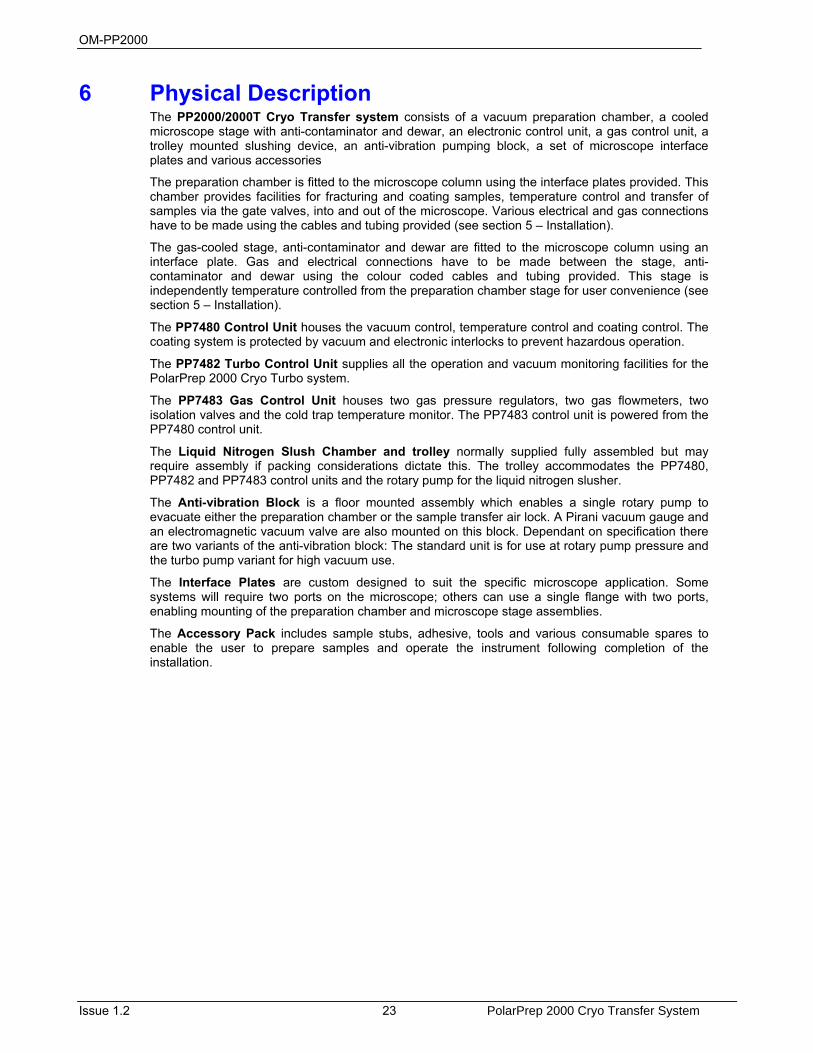
6 Physical Description The PP2000/2000T Cryo Transfer system consists of a vacuum preparation chamber, a cooled microscope stage with anti-contaminator and dewar, an electronic control unit, a gas control unit, a trolley mounted slushing device, an anti-vibration pumping block, a set of microscope interface plates and various accessories
The preparation chamber is fitted to the microscope column using the interface plates provided. This chamber provides facilities for fracturing and coating samples, temperature control and transfer of samples via the gate valves, into and out of the microscope. Various electrical and gas connections have to be made using the cables and tubing provided (see section 5 – Installation).
The gas-cooled stage, anti-contaminator and dewar are fitted to the microscope column using an interface plate. Gas and electrical connections have to be made between the stage, anti-contaminator and dewar using the colour coded cables and tubing provided. This stage is independently temperature controlled from the preparation chamber stage for user convenience (see section 5 – Installation).
The PP7480 Control Unit houses the vacuum control, temperature control and coating control. The coating system is protected by vacuum and electronic interlocks to prevent hazardous operation.
The PP7482 Turbo Control Unit supplies all the operation and vacuum monitoring facilities for the PolarPrep 2000 Cryo Turbo system.
The PP7483 Gas Control Unit houses two gas pressure regulators, two gas flowmeters, two isolation valves and the cold trap temperature monitor. The PP7483 control unit is powered from the PP7480 control unit.
The Liquid Nitrogen Slush Chamber and trolley normally supplied fully assembled but may require assembly if packing considerations dictate this. The trolley accommodates the PP7480, PP7482 and PP7483 control units and the rotary pump for the liquid nitrogen slusher.
The Anti-vibration Block is a floor mounted assembly which enables a single rotary pump to evacuate either the preparation chamber or the sample transfer air lock. A Pirani vacuum gauge and an electromagnetic vacuum valve are also mounted on this block. Dependant on specification there are two variants of the anti-vibration block: The standard unit is for use at rotary pump pressure and the turbo pump variant for high vacuum use.
The Interface Plates are custom designed to suit the specific microscope application. Some systems will require two ports on the microscope; others can use a single flange with two ports, enabling mounting of the preparation chamber and microscope stage assemblies.
The Accessory Pack includes sample stubs, adhesive, tools and various consumable spares to enable the user to prepare samples and operate the instrument following completion of the installation.
OM-PP2000
PolarPrep 2000 Cryo Transfer System 24 Issue 1.2
6.1 Preparation Chamber
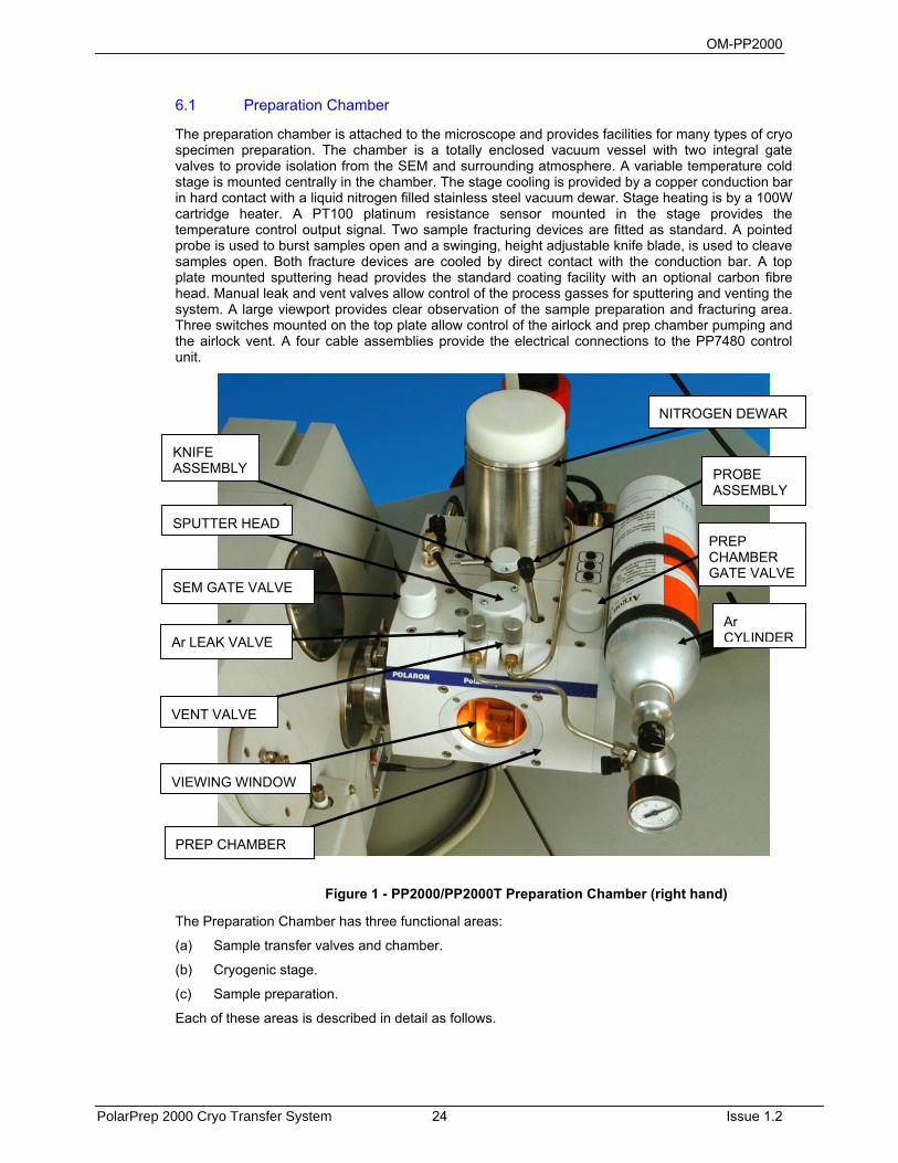
The preparation chamber is attached to the microscope and provides facilities for many types of cryo specimen preparation. The chamber is a totally enclosed vacuum vessel with two integral gate valves to provide isolation from the SEM and surrounding atmosphere. A variable temperature cold stage is mounted centrally in the chamber. The stage cooling is provided by a copper conduction bar in hard contact with a liquid nitrogen filled stainless steel vacuum dewar. Stage heating is by a 100W cartridge heater. A PT100 platinum resistance sensor mounted in the stage provides the temperature control output signal. Two sample fracturing devices are fitted as standard. A pointed probe is used to burst samples open and a swinging, height adjustable knife blade, is used to cleave samples open. Both fracture devices are cooled by direct contact with the conduction bar. A top plate mounted sputtering head provides the standard coating facility with an optional carbon fibre head. Manual leak and vent valves allow control of the process gasses for sputtering and venting the system. A large viewport provides clear observation of the sample preparation and fracturing area. Three switches mounted on the top plate allow control of the airlock and prep chamber pumping and the airlock vent. A four cable assemblies provide the electrical connections to the PP7480 control unit.
The Preparation Chamber has three functional areas:
(a) Sample transfer valves and chamber.
(b) Cryogenic stage.
(c) Sample preparation.
Each of these areas is described in detail as follows.
Figure 1 - PP2000/PP2000T Preparation Chamber (right hand)
KNIFE ASSEMBLY
SPUTTER HEAD
SEM GATE VALVE
Ar LEAK VALVE
VENT VALVE
PREP CHAMBER
NITROGEN DEWAR
PROBE ASSEMBLY
PREP CHAMBER GATE VALVE
Ar CYLINDER
VIEWING WINDOW

OM-PP2000
Issue 1.2 25 PolarPrep 2000 Cryo Transfer System
6.2 PP7409 Transfer Device
In operation, samples are rapidly frozen in the liquid nitrogen slush chamber and transferred to the preparation chamber in a sealed vacuum transfer device. The transfer device is loaded onto the air lock which is then evacuated. When the pressure in the air lock is equal to that in the preparation chamber the air lock gate valve followed by the transfer device door may be opened (assuming the main prep chamber is under vacuum). The sample can now be transferred to the dovetail stage in the preparation chamber.
Following preparation and coating the sample may be transferred to the microscope by opening the SEM gate valve and moving the sample shuttle with the transfer rod. The location of the sample shuttle into the microscope stage can be highlighted with the SEM lamp and observed via the large viewing window in the transfer chamber. Samples may be withdrawn from the microscope and the preparation chamber in the same manner. When withdrawing samples, it is essential that each gate valve is closed when the sample has passed through. To finally remove a sample from the system the airlock gate valve must be closed and the airlock vented.
CLOSED OPEN
6.3 Cryogenic Stage
The dovetail stage in the preparation chamber is cooled by a copper conduction bar in hard contact with a liquid nitrogen storage dewar. The walls of the dewar provide effective cold trapping and cryo pumping of the preparation chamber.
To achieve temperature control of the stage a cartridge heater and a temperature sensor are also mounted in the stage block. Surrounding the stage is a cooled catch tray which acts as an additional cold trap for fracture debris.
The conduction bar also provides the cooling and lower bearing for the swinging arm knife assembly and the fracturing probe assembly.
6.4 Sample Preparation
Within the preparation chamber, samples may be fractured, etched (sublimed) and coated at any temperature within the range of the cooled stage, normally between -900C & -1000C dependent on vacuum levels.
Fitted as standard to the PP2000 are two fracturing devices, the probe for crushing and picking samples, and the knife for cleaving samples. Both these devices are parked on the conduction bar for cooling. The swinging knife may also be used as a cold trap above the sample when etching.
A sputtering head is also standard on the PP2000 to provide conductive coatings. An optional LT7416 carbon fibre evaporation head may be fitted in place of the sputtering head for X-ray analysis functions. The sputtering process is normally controlled by the standard timer; an optional PP7690 film thickness monitor is available to display the actual coating thickness.
Figure 2 - Transfer Device – Closed and Open
OM-PP2000
PolarPrep 2000 Cryo Transfer System 26 Issue 1.2
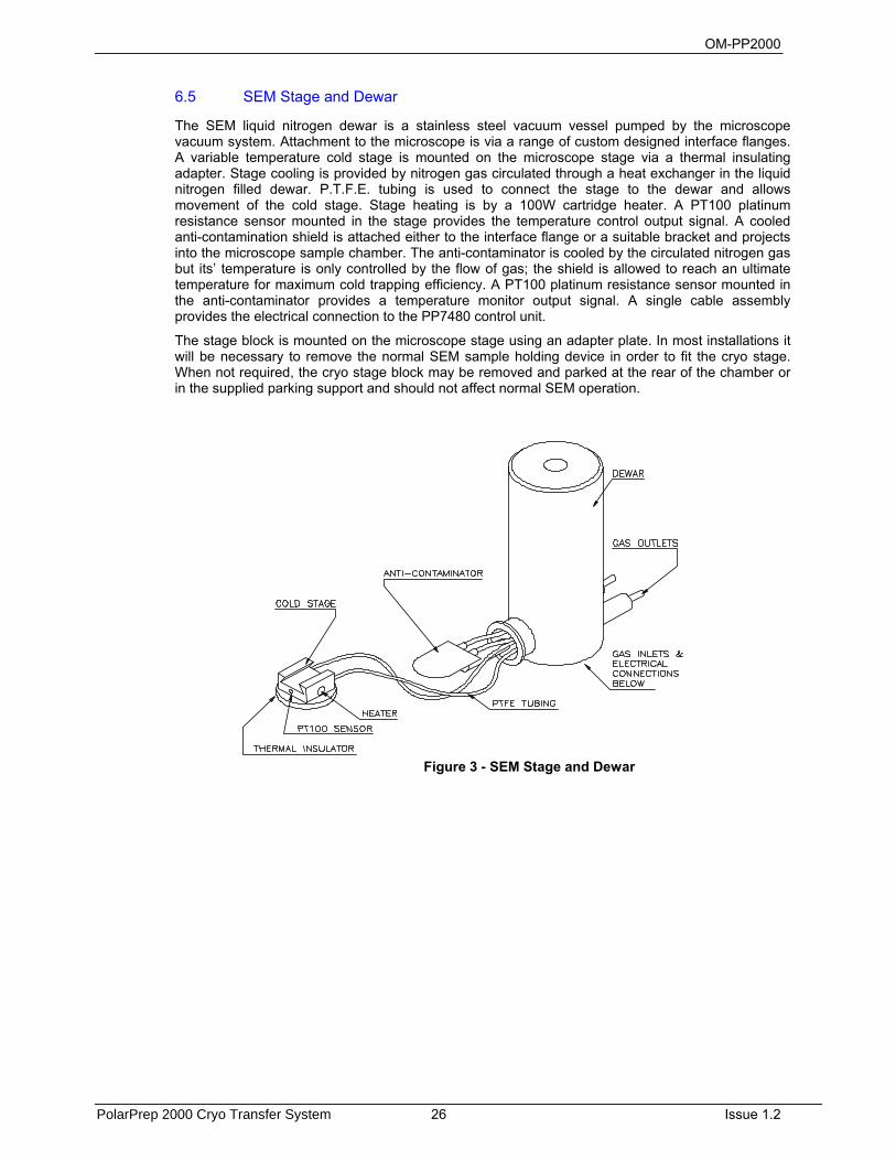
6.5 SEM Stage and Dewar
The SEM liquid nitrogen dewar is a stainless steel vacuum vessel pumped by the microscope vacuum system. Attachment to the microscope is via a range of custom designed interface flanges. A variable temperature cold stage is mounted on the microscope stage via a thermal insulating adapter. Stage cooling is provided by nitrogen gas circulated through a heat exchanger in the liquid nitrogen filled dewar. P.T.F.E. tubing is used to connect the stage to the dewar and allows movement of the cold stage. Stage heating is by a 100W cartridge heater. A PT100 platinum resistance sensor mounted in the stage provides the temperature control output signal. A cooled anti-contamination shield is attached either to the interface flange or a suitable bracket and projects into the microscope sample chamber. The anti-contaminator is cooled by the circulated nitrogen gas but its’ temperature is only controlled by the flow of gas; the shield is allowed to reach an ultimate temperature for maximum cold trapping efficiency. A PT100 platinum resistance sensor mounted in the anti-contaminator provides a temperature monitor output signal. A single cable assembly provides the electrical connection to the PP7480 control unit.
The stage block is mounted on the microscope stage using an adapter plate. In most installations it will be necessary to remove the normal SEM sample holding device in order to fit the cryo stage. When not required, the cryo stage block may be removed and parked at the rear of the chamber or in the supplied parking support and should not affect normal SEM operation.
Figure 3 - SEM Stage and Dewar
OM-PP2000
Issue 1.2 27 PolarPrep 2000 Cryo Transfer System
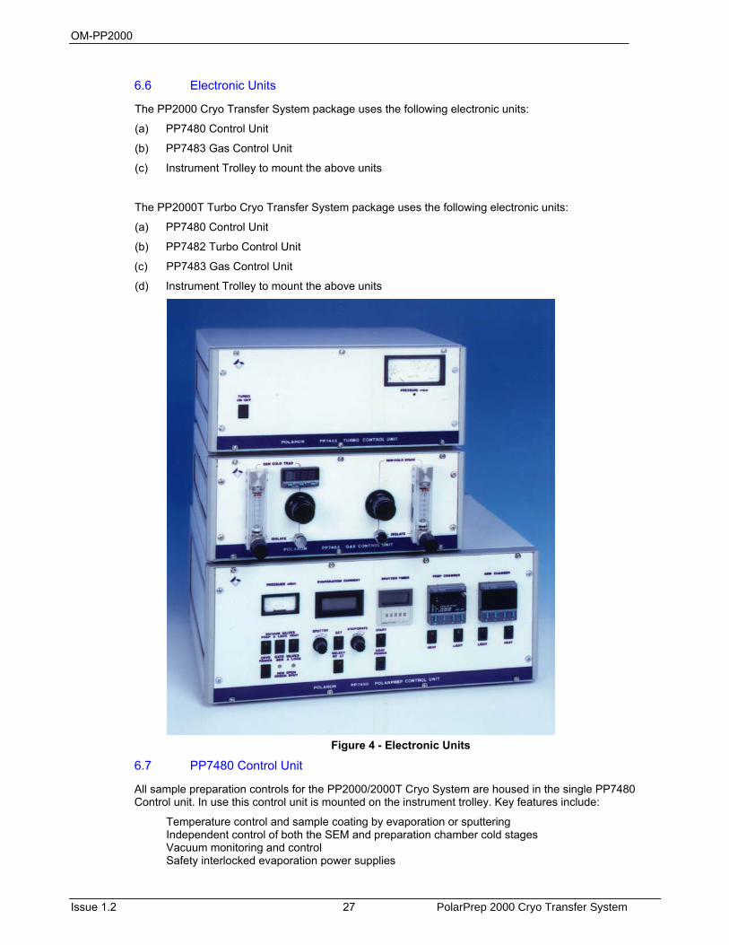
6.6 Electronic Units
The PP2000 Cryo Transfer System package uses the following electronic units:
(a) PP7480 Control Unit
(b) PP7483 Gas Control Unit
(c) Instrument Trolley to mount the above units
The PP2000T Turbo Cryo Transfer System package uses the following electronic units:
(a) PP7480 Control Unit
(b) PP7482 Turbo Control Unit
(c) PP7483 Gas Control Unit
(d) Instrument Trolley to mount the above units
Figure 4 - Electronic Units
6.7 PP7480 Control Unit
All sample preparation controls for the PP2000/2000T Cryo System are housed in the single PP7480 Control unit. In use this control unit is mounted on the instrument trolley. Key features include:
Temperature control and sample coating by evaporation or sputtering Independent control of both the SEM and preparation chamber cold stages Vacuum monitoring and control Safety interlocked evaporation power supplies
OM-PP2000
PolarPrep 2000 Cryo Transfer System 28 Issue 1.2
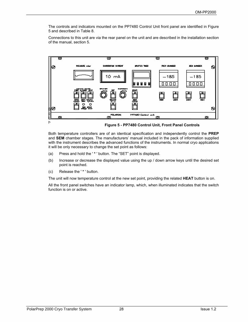
The controls and indicators mounted on the PP7480 Control Unit front panel are identified in Figure 5 and described in Table 8.
Connections to this unit are via the rear panel on the unit and are described in the installation section of the manual, section 5.
Both
Both temperature controllers are of an identical specification and independently control the PREP and SEM chamber stages. The manufacturers’ manual included in the pack of information supplied with the instrument describes the advanced functions of the instruments. In normal cryo applications it will be only necessary to change the set point as follows:
(a) Press and hold the ' * ' button. The “SET” point is displayed.
(b) Increase or decrease the displayed value using the up / down arrow keys until the desired set point is reached.
(c) Release the ' * ' button.
The unit will now temperature control at the new set point, providing the related HEAT button is on.
All the front panel switches have an indicator lamp, which, when illuminated indicates that the switch function is on or active.
Figure 5 - PP7480 Control Unit, Front Panel Controls
OM-PP2000
Issue 1.2 29 PolarPrep 2000 Cryo Transfer System
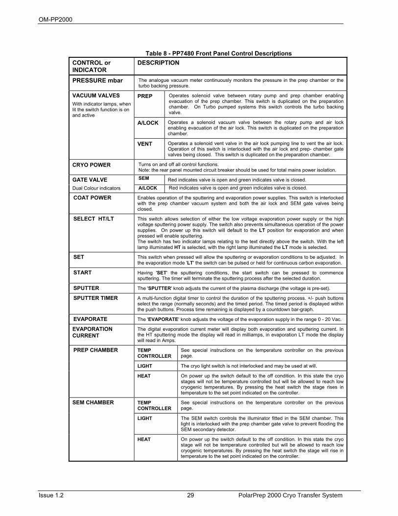
Table 8 - PP7480 Front Panel Control Descriptions
CONTROL or INDICATOR
DESCRIPTION
PRESSURE mbar The analogue vacuum meter continuously monitors the pressure in the prep chamber or the turbo backing pressure.
VACUUM VALVES With indicator lamps, when lit the switch function is on and active
PREP Operates solenoid valve between rotary pump and prep chamber enabling evacuation of the prep chamber. This switch is duplicated on the preparation chamber. On Turbo pumped systems this switch controls the turbo backing valve.
A/LOCK Operates a solenoid vacuum valve between the rotary pump and air lock enabling evacuation of the air lock. This switch is duplicated on the preparation chamber.
VENT Operates a solenoid vent valve in the air lock pumping line to vent the air lock. Operation of this switch is interlocked with the air lock and prep- chamber gate valves being closed. This switch is duplicated on the preparation chamber.
CRYO POWER Turns on and off all control functions. Note: the rear panel mounted circuit breaker should be used for total mains power isolation.
GATE VALVE Dual Colour indicators
SEM Red indicates valve is open and green indicates valve is closed. A/LOCK Red indicates valve is open and green indicates valve is closed.
COAT POWER Enables operation of the sputtering and evaporation power supplies. This switch is interlocked with the prep chamber vacuum system and both the air lock and SEM gate valves being closed.
SELECT HT/LT This switch allows selection of either the low voltage evaporation power supply or the high voltage sputtering power supply. The switch also prevents simultaneous operation of the power supplies. On power up this switch will default to the LT position for evaporation and when pressed will enable sputtering. The switch has two indicator lamps relating to the text directly above the switch. With the left lamp illuminated HT is selected, with the right lamp illuminated the LT mode is selected.
SET This switch when pressed will allow the sputtering or evaporation conditions to be adjusted. In the evaporation mode 'LT' the switch can be pulsed or held for continuous carbon evaporation.
START Having 'SET' the sputtering conditions, the start switch can be pressed to commence sputtering. The timer will terminate the sputtering process after the selected duration.
SPUTTER The 'SPUTTER' knob adjusts the current of the plasma discharge (the voltage is pre-set).
SPUTTER TIMER A multi-function digital timer to control the duration of the sputtering process. +/- push buttons select the range (normally seconds) and the timed period. The timed period is displayed within the push buttons. Process time remaining is displayed by a countdown bar-graph.
EVAPORATE The 'EVAPORATE' knob adjusts the voltage of the evaporation supply in the range 0 - 20 Vac.
EVAPORATION CURRENT
The digital evaporation current meter will display both evaporation and sputtering current. In the HT sputtering mode the display will read in milliamps, in evaporation LT mode the display will read in Amps.
PREP CHAMBER TEMP CONTROLLER
See special instructions on the temperature controller on the previous page.
LIGHT The cryo light switch is not interlocked and may be used at will. HEAT On power up the switch default to the off condition. In this state the cryo
stages will not be temperature controlled but will be allowed to reach low cryogenic temperatures. By pressing the heat switch the stage rises in temperature to the set point indicated on the controller.
SEM CHAMBER TEMP CONTROLLER
See special instructions on the temperature controller on the previous page.
LIGHT The SEM switch controls the illuminator fitted in the SEM chamber. This light is interlocked with the prep chamber gate valve to prevent flooding the SEM secondary detector.
HEAT On power up the switch default to the off condition. In this state the cryo stage will not be temperature controlled but will be allowed to reach low cryogenic temperatures. By pressing the heat switch the stage will rise in temperature to the set point indicated on the controller.
OM-PP2000
PolarPrep 2000 Cryo Transfer System 30 Issue 1.2
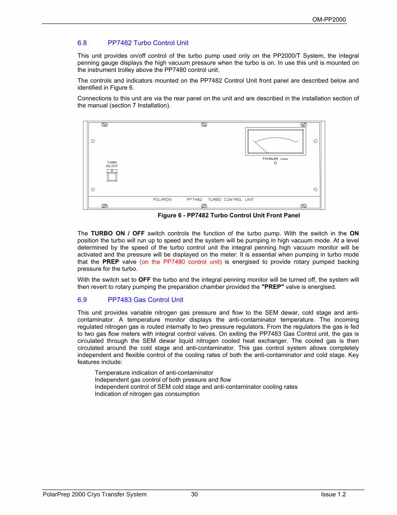
6.8 PP7482 Turbo Control Unit
This unit provides on/off control of the turbo pump used only on the PP2000/T System, the integral penning gauge displays the high vacuum pressure when the turbo is on. In use this unit is mounted on the instrument trolley above the PP7480 control unit.
The controls and indicators mounted on the PP7482 Control Unit front panel are described below and identified in Figure 6.
Connections to this unit are via the rear panel on the unit and are described in the installation section of the manual (section 7 Installation).
The TURBO ON / OFF switch controls the function of the turbo pump. With the switch in the ON position the turbo will run up to speed and the system will be pumping in high vacuum mode. At a level determined by the speed of the turbo control unit the integral penning high vacuum monitor will be activated and the pressure will be displayed on the meter. It is essential when pumping in turbo mode that the PREP valve (on the PP7480 control unit) is energised to provide rotary pumped backing pressure for the turbo.
With the switch set to OFF the turbo and the integral penning monitor will be turned off, the system will then revert to rotary pumping the preparation chamber provided the "PREP" valve is energised.
6.9 PP7483 Gas Control Unit
This unit provides variable nitrogen gas pressure and flow to the SEM dewar, cold stage and anti-contaminator. A temperature monitor displays the anti-contaminator temperature. The incoming regulated nitrogen gas is routed internally to two pressure regulators. From the regulators the gas is fed to two gas flow meters with integral control valves. On exiting the PP7483 Gas Control unit, the gas is circulated through the SEM dewar liquid nitrogen cooled heat exchanger. The cooled gas is then circulated around the cold stage and anti-contaminator. This gas control system allows completely independent and flexible control of the cooling rates of both the anti-contaminator and cold stage. Key features include:
Temperature indication of anti-contaminator Independent gas control of both pressure and flow Independent control of SEM cold stage and anti-contaminator cooling rates Indication of nitrogen gas consumption
Figure 6 - PP7482 Turbo Control Unit Front Panel
OM-PP2000
Issue 1.2 31 PolarPrep 2000 Cryo Transfer System
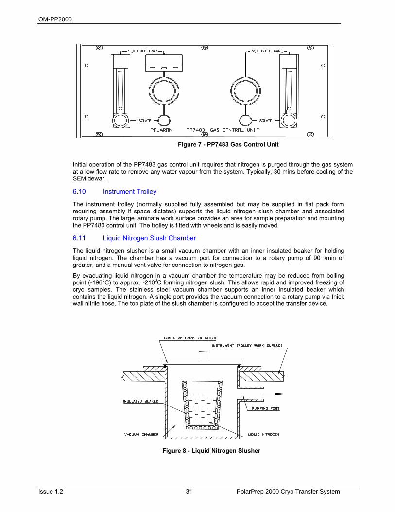
Initial operation of the PP7483 gas control unit requires that nitrogen is purged through the gas system at a low flow rate to remove any water vapour from the system. Typically, 30 mins before cooling of the SEM dewar.
6.10 Instrument Trolley
The instrument trolley (normally supplied fully assembled but may be supplied in flat pack form requiring assembly if space dictates) supports the liquid nitrogen slush chamber and associated rotary pump. The large laminate work surface provides an area for sample preparation and mounting the PP7480 control unit. The trolley is fitted with wheels and is easily moved.
6.11 Liquid Nitrogen Slush Chamber
The liquid nitrogen slusher is a small vacuum chamber with an inner insulated beaker for holding liquid nitrogen. The chamber has a vacuum port for connection to a rotary pump of 90 l/min or greater, and a manual vent valve for connection to nitrogen gas.
By evacuating liquid nitrogen in a vacuum chamber the temperature may be reduced from boiling point (-1960C) to approx. -2100C forming nitrogen slush. This allows rapid and improved freezing of cryo samples. The stainless steel vacuum chamber supports an inner insulated beaker which contains the liquid nitrogen. A single port provides the vacuum connection to a rotary pump via thick wall nitrile hose. The top plate of the slush chamber is configured to accept the transfer device.
Figure 8 - Liquid Nitrogen Slusher
Figure 7 - PP7483 Gas Control Unit

OM-PP2000
PolarPrep 2000 Cryo Transfer System 32 Issue 1.2
6.12 Anti-vibration Pumping Block
Since SEM microscopes are sensitive to external vibration, it is essential that the pumping lines to the preparation chamber and air lock are damped. The anti-vibration pumping block is floor mounted adjacent to the preparation chamber. There are two types available; the PP2000 Cryo System uses the basic Anti-vibration Pumping Block (section 6.13) and the PP2000T Turbo Cryo System uses the Turbo Anti-vibration Pumping Block (section 6.14).
6.13 PP2000 Anti-vibration Pumping Block
This block has a solenoid-operated vacuum isolation valve configured to suit the pumping requirements of the preparation chamber and airlock. Vacuum connections to the rotary pump, preparation chamber and airlock are by thick wall nitrile vacuum hose. Mounted on the anti-vibration block is a Pirani gauge head. All rotary pump vibrations are damped by the large mass of the block assembly. Captive leads provide the required electrical connections to the PP7480 control unit. In practice, the airlock vacuum isolation and airlock vent valves are mounted directly on the preparation chamber to provide clean vacuum conditions during cryo processes.
6.14 PP2000T Turbo Anti-vibration Pumping Block
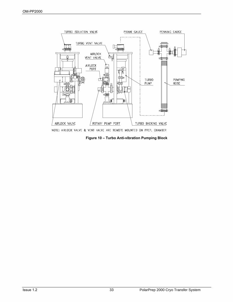
This block has a solenoid-operated vacuum isolation valve, the turbo pump and a manual turbo vent valve configured to suit the pumping requirements of the preparation chamber and air lock. Above the turbo pump is a manually operated valve for pump isolation from the preparation chamber. Vacuum connection to the rotary pump and airlock is by thick wall nitrile vacuum hose. Vacuum connection to the preparation chamber is by a stainless steel bellows hose. Mounted on the hose are a Pirani and a Penning gauge head. The turbo pump vibrations are damped by the large mass of the block assembly. Captive flying leads provide the required electrical connections to the PP7480 control unit and the PP7482 Turbo control unit.
Figure 9 – Anti-vibration Pumping Block
OM-PP2000
Issue 1.2 33 PolarPrep 2000 Cryo Transfer System
Figure 10 – Turbo Anti-vibration Pumping Block

OM-PP2000
PolarPrep 2000 Cryo Transfer System 34 Issue 1.2
OM-PP2000
Issue 1.2 35 PolarPrep 2000 Cryo Transfer System
7 Installation Quorum Technologies has carefully packed the PP2000 Cryo Transfer System equipment so that it will reach its destination in perfect operating order. Do NOT discard any packing materials until the unit has been inspected for any transit damage and the instrument has been used to the customers satisfaction.
If any damage is found, notify the carrier and Quorum Technologies (or local agent) immediately. If it is necessary to return the shipment, use the packaging as supplied and follow the instructions in this manual for return of goods paragraph 3.1.
7.1 Unpacking Checklist
The Equipment package will normally be despatched from the factory in several cardboard boxes depending on the system ordered. Inside the boxes the following will be found, refer and check each item off against the supplied packing list.
7.2 Preparation (a) Ensure that a suitable mains electricity supply (110 V ac or 240 V ac, frequency 50/60 Hz)
is available. Check that the voltage label attached to the side of the cabinet is suitable for the local voltage and frequency.
A complete PP2000 Cryoprep installation will require 4 separate mains power outlets of 10A (240v) and 20A (110v). If the optional PP7690 Film thickness monitor accessory and stereo microscope are fitted an additional mains power outlet will be required. (Note: PP7690 may be powered from integral interlocked output on PP7480 control unit rear panel).
(b) The following gas supplies are required; ensure that a suitable gas supply is available.
Nitrogen gas. Two x 250 cubic foot cylinders of dry nitrogen gas (ZERO grade < 3 vpm H2O) with regulators, to operate in the pressure range 0-30 psi (0-1 Kg cm-2, 0-2 bar). If the optional pressurised dewar is specified, only one nitrogen gas cylinder will be required for venting purposes.
Liquid nitrogen. It is convenient to have a 160 litre bulk storage dewar of liquid nitrogen which can be used to fill 1 or 5 litre dewar containers for subsequently filling both dewars on the PolarPrep 2000 Cryo Transfer system and the slusher chamber.
Argon gas. One 250 cubic foot cylinder of dry Argon gas (ZERO grade) with regulator, to operate in the pressure range 0-15psi (0-1 Kg cm-2, 0-1 bar). This gas is used when sputter coating, this size cylinder should last approximately 6 months provided the cylinder is turned off after use.
(c) Ensure that a suitable vacuum pump is available.
Where a rotary pump is used, ensure that the rotary pump has been filled with oil, in accordance with the manufacturers’ instructions. The exhaust should be filtered or expelled to a safe area. All pumps supplied by Quorum Technologies are fitted with an exhaust oil mist filter.
7.3 PP2000/PP2000T Installation
WARNING HAZARD TO HEALTH!
Potentially lethal voltages are used in this equipment. Before making / breaking connections to the equipment, ensure power is
switched off and that it is safe to proceed.
Installation is recommended by a Quorum Technologies representative. Should this not be possible, please use the following procedure.
Ensure that the microscope is performing correctly before proceeding with the installation; a high resolution reference image should be taken for subsequent comparison.
OM-PP2000
PolarPrep 2000 Cryo Transfer System 36 Issue 1.2
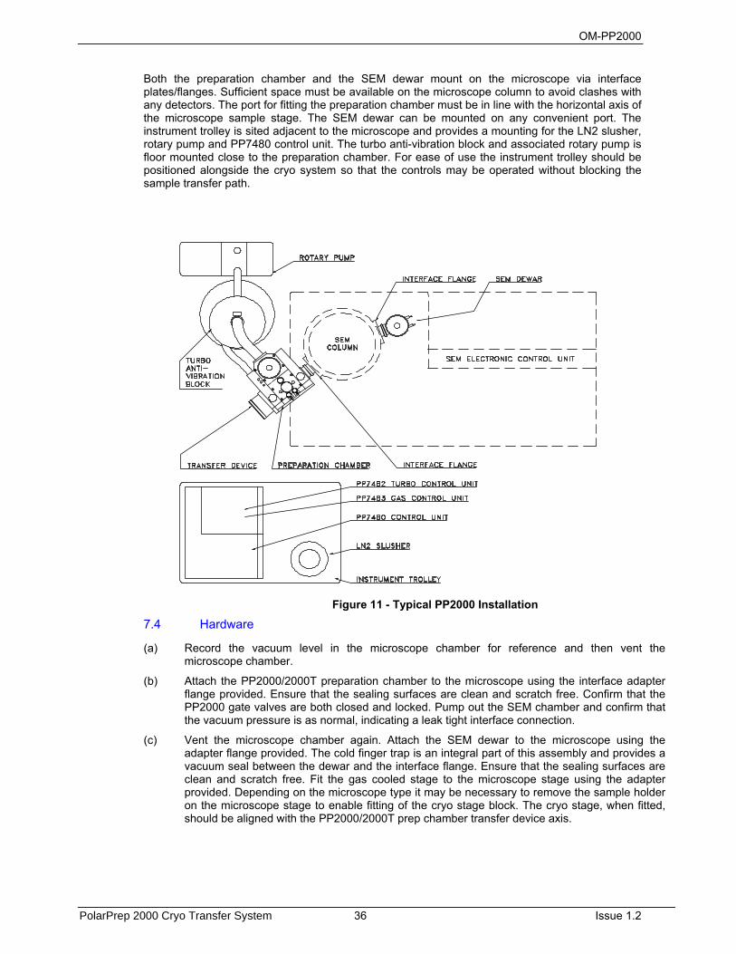
Both the preparation chamber and the SEM dewar mount on the microscope via interface plates/flanges. Sufficient space must be available on the microscope column to avoid clashes with any detectors. The port for fitting the preparation chamber must be in line with the horizontal axis of the microscope sample stage. The SEM dewar can be mounted on any convenient port. The instrument trolley is sited adjacent to the microscope and provides a mounting for the LN2 slusher, rotary pump and PP7480 control unit. The turbo anti-vibration block and associated rotary pump is floor mounted close to the preparation chamber. For ease of use the instrument trolley should be positioned alongside the cryo system so that the controls may be operated without blocking the sample transfer path.
7.4 Hardware
(a) Record the vacuum level in the microscope chamber for reference and then vent the microscope chamber.
(b) Attach the PP2000/2000T preparation chamber to the microscope using the interface adapter flange provided. Ensure that the sealing surfaces are clean and scratch free. Confirm that the PP2000 gate valves are both closed and locked. Pump out the SEM chamber and confirm that the vacuum pressure is as normal, indicating a leak tight interface connection.
(c) Vent the microscope chamber again. Attach the SEM dewar to the microscope using the adapter flange provided. The cold finger trap is an integral part of this assembly and provides a vacuum seal between the dewar and the interface flange. Ensure that the sealing surfaces are clean and scratch free. Fit the gas cooled stage to the microscope stage using the adapter provided. Depending on the microscope type it may be necessary to remove the sample holder on the microscope stage to enable fitting of the cryo stage block. The cryo stage, when fitted, should be aligned with the PP2000/2000T prep chamber transfer device axis.
Figure 11 - Typical PP2000 Installation
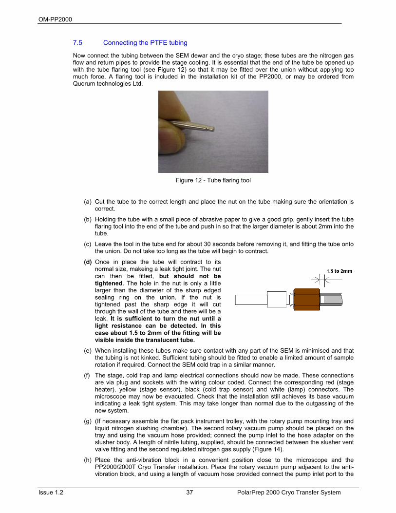
OM-PP2000
Issue 1.2 37 PolarPrep 2000 Cryo Transfer System
7.5 Connecting the PTFE tubing
Now connect the tubing between the SEM dewar and the cryo stage; these tubes are the nitrogen gas flow and return pipes to provide the stage cooling. It is essential that the end of the tube be opened up with the tube flaring tool (see Figure 12) so that it may be fitted over the union without applying too much force. A flaring tool is included in the installation kit of the PP2000, or may be ordered from Quorum technologies Ltd.
Figure 12 - Tube flaring tool
(a) Cut the tube to the correct length and place the nut on the tube making sure the orientation is correct.
(b) Holding the tube with a small piece of abrasive paper to give a good grip, gently insert the tube flaring tool into the end of the tube and push in so that the larger diameter is about 2mm into the tube.
(c) Leave the tool in the tube end for about 30 seconds before removing it, and fitting the tube onto the union. Do not take too long as the tube will begin to contract.
(d) Once in place the tube will contract to its normal size, makeing a leak tight joint. The nut can then be fitted, but should not be tightened. The hole in the nut is only a little larger than the diameter of the sharp edged sealing ring on the union. If the nut is tightened past the sharp edge it will cut through the wall of the tube and there will be a leak. It is sufficient to turn the nut until a light resistance can be detected. In this case about 1.5 to 2mm of the fitting will be visible inside the translucent tube.
(e) When installing these tubes make sure contact with any part of the SEM is minimised and that the tubing is not kinked. Sufficient tubing should be fitted to enable a limited amount of sample rotation if required. Connect the SEM cold trap in a similar manner.
(f) The stage, cold trap and lamp electrical connections should now be made. These connections are via plug and sockets with the wiring colour coded. Connect the corresponding red (stage heater), yellow (stage sensor), black (cold trap sensor) and white (lamp) connectors. The microscope may now be evacuated. Check that the installation still achieves its base vacuum indicating a leak tight system. This may take longer than normal due to the outgassing of the new system.
(g) (If necessary assemble the flat pack instrument trolley, with the rotary pump mounting tray and liquid nitrogen slushing chamber). The second rotary vacuum pump should be placed on the tray and using the vacuum hose provided; connect the pump inlet to the hose adapter on the slusher body. A length of nitrile tubing, supplied, should be connected between the slusher vent valve fitting and the second regulated nitrogen gas supply (Figure 14).
(h) Place the anti-vibration block in a convenient position close to the microscope and the PP2000/2000T Cryo Transfer installation. Place the rotary vacuum pump adjacent to the anti-vibration block, and using a length of vacuum hose provided connect the pump inlet port to the
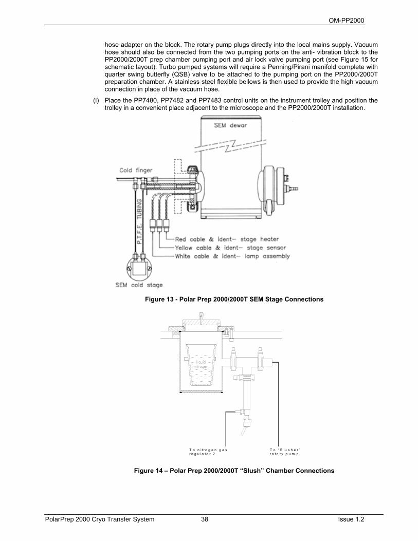
OM-PP2000
PolarPrep 2000 Cryo Transfer System 38 Issue 1.2
hose adapter on the block. The rotary pump plugs directly into the local mains supply. Vacuum hose should also be connected from the two pumping ports on the anti- vibration block to the PP2000/2000T prep chamber pumping port and air lock valve pumping port (see Figure 15 for schematic layout). Turbo pumped systems will require a Penning/Pirani manifold complete with quarter swing butterfly (QSB) valve to be attached to the pumping port on the PP2000/2000T preparation chamber. A stainless steel flexible bellows is then used to provide the high vacuum connection in place of the vacuum hose.
(i) Place the PP7480, PP7482 and PP7483 control units on the instrument trolley and position the trolley in a convenient place adjacent to the microscope and the PP2000/2000T installation.
Figure 13 - Polar Prep 2000/2000T SEM Stage Connections
T o “ S lu s h e r ”r o t a r y p u m p
T o n i t r o g e n g a sr e g u la t o r 2
Figure 14 – Polar Prep 2000/2000T “Slush” Chamber Connections

OM-PP2000
Issue 1.2 39 PolarPrep 2000 Cryo Transfer System
T o r o t a r y p u m p
T o N 2 g a s r e g u la t o r 2
T o A r g o n g a s r e g u la t o r 5 p s i
T o N 2 g a s r e g u la t o r 2
P i r a n i h e a d
V e n t V a l v e
P r e p c h a m b e r p u m p in g l i n e
A i r l o c kp u m p in g l i n e
Figure 15 – Polar Prep 2000/2000T Vacuum Tubing Layout
7.6 Connections
(a) Connect all the control cables labelled from the PP7480 control unit rear panel to the PP2000/2000T prep chamber, the SEM dewar and the anti-vibration block (see Figure 14 & Figure 16). Connect the gas tubing as follows and detailed in Figure 17.
(i) From the nitrogen gas regulated supply or pressurised dewar (15 psi) to the 'GAS IN' fitting on the PP7483 rear panel.
(iii) From the Cold stage FLOW fitting on the rear panel to the SEM dewar stage gas fitting on the base of the dewar (marked S).
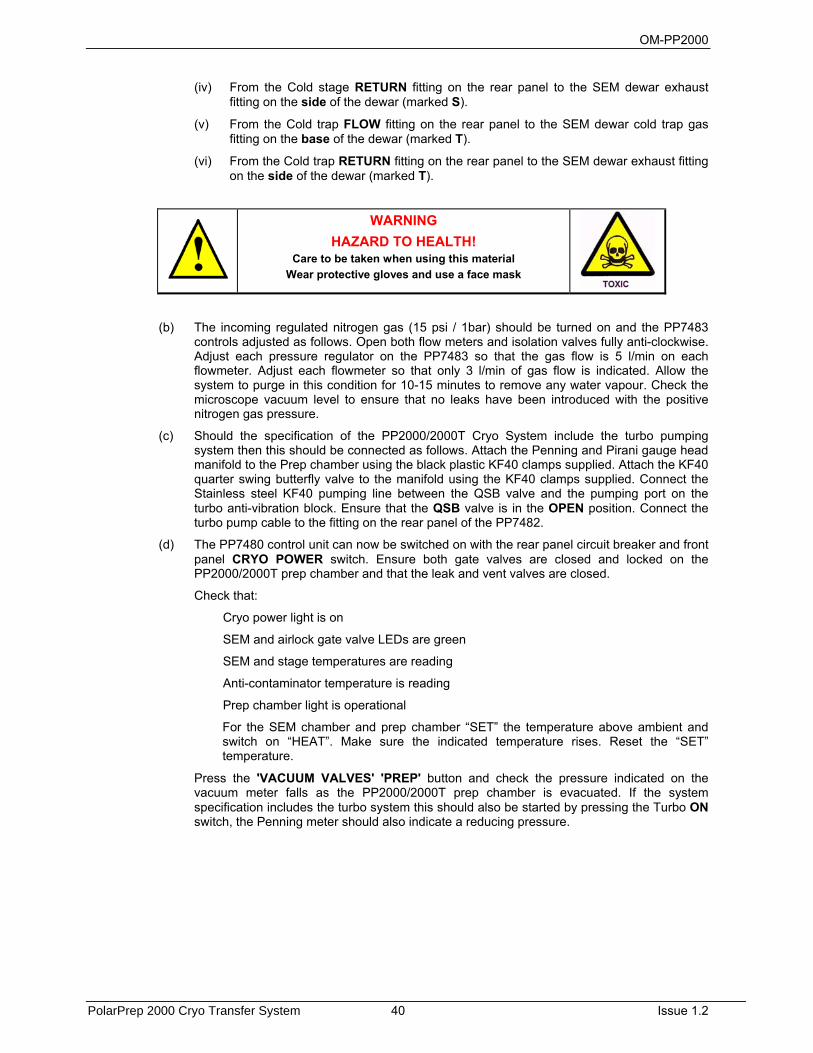
OM-PP2000
PolarPrep 2000 Cryo Transfer System 40 Issue 1.2
(iv) From the Cold stage RETURN fitting on the rear panel to the SEM dewar exhaust fitting on the side of the dewar (marked S).
(v) From the Cold trap FLOW fitting on the rear panel to the SEM dewar cold trap gas fitting on the base of the dewar (marked T).
(vi) From the Cold trap RETURN fitting on the rear panel to the SEM dewar exhaust fitting on the side of the dewar (marked T).
WARNING HAZARD TO HEALTH!
Care to be taken when using this material Wear protective gloves and use a face mask
(b) The incoming regulated nitrogen gas (15 psi / 1bar) should be turned on and the PP7483 controls adjusted as follows. Open both flow meters and isolation valves fully anti-clockwise. Adjust each pressure regulator on the PP7483 so that the gas flow is 5 l/min on each flowmeter. Adjust each flowmeter so that only 3 l/min of gas flow is indicated. Allow the system to purge in this condition for 10-15 minutes to remove any water vapour. Check the microscope vacuum level to ensure that no leaks have been introduced with the positive nitrogen gas pressure.
(c) Should the specification of the PP2000/2000T Cryo System include the turbo pumping system then this should be connected as follows. Attach the Penning and Pirani gauge head manifold to the Prep chamber using the black plastic KF40 clamps supplied. Attach the KF40 quarter swing butterfly valve to the manifold using the KF40 clamps supplied. Connect the Stainless steel KF40 pumping line between the QSB valve and the pumping port on the turbo anti-vibration block. Ensure that the QSB valve is in the OPEN position. Connect the turbo pump cable to the fitting on the rear panel of the PP7482.
(d) The PP7480 control unit can now be switched on with the rear panel circuit breaker and front panel CRYO POWER switch. Ensure both gate valves are closed and locked on the PP2000/2000T prep chamber and that the leak and vent valves are closed.
Check that:
Cryo power light is on
SEM and airlock gate valve LEDs are green
SEM and stage temperatures are reading
Anti-contaminator temperature is reading
Prep chamber light is operational
For the SEM chamber and prep chamber “SET” the temperature above ambient and switch on “HEAT”. Make sure the indicated temperature rises. Reset the “SET” temperature.
Press the 'VACUUM VALVES' 'PREP' button and check the pressure indicated on the vacuum meter falls as the PP2000/2000T prep chamber is evacuated. If the system specification includes the turbo system this should also be started by pressing the Turbo ON switch, the Penning meter should also indicate a reducing pressure.
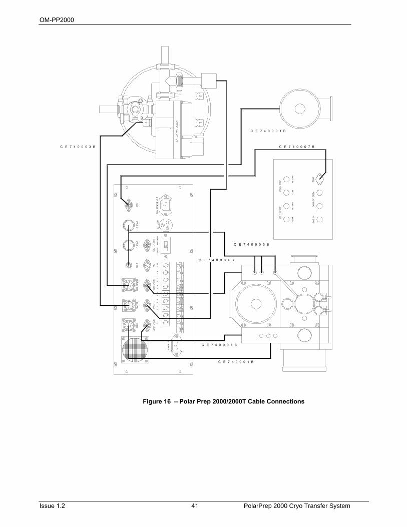
OM-PP2000
Issue 1.2 41 PolarPrep 2000 Cryo Transfer System
C E 7 4 0 0 0 7 B
C E 7 4 0 0 0 1 B
C E 7 4 0 0 0 3 B
C E 7 4 0 0 0 5 B
C E 7 4 0 0 0 1 B
C E 7 4 0 0 0 4 B
C E 7 4 0 0 0 4 B
Figure 16 – Polar Prep 2000/2000T Cable Connections

OM-PP2000
PolarPrep 2000 Cryo Transfer System 42 Issue 1.2
COLD
STA
GE
CO
LD T
RAP
FLO
WRE
TURN
FLO
WR
ETUR
N
GAS
IN
EXH
AUST
GAS
TEM
P
SEM
DEW
AR
GAS
FLO
W C
ONN
ECTI
ON
S
GAS
RET
URN
CONN
ECTI
ONS
HIG
H PU
RITY
(99.
999%
)NI
TRO
GEN
CYL
INDE
RAN
D 2
STAG
E RE
GUL
ATO
RAT
1-2
BAR
PRE
SSUR
E O
RSE
LF P
RES
SURI
SING
DEW
AR
Figure 17 – Polar Prep 2000/2000T Dewar Gas Connections
OM-PP2000
Issue 1.2 43 PolarPrep 2000 Cryo Transfer System
7.7 Alignment
The alignment of the PP2000/2000T specimen transfer device and the SEM mounted cold stage can now be set and the microscope stage position noted as follows:
(a) Mount a dovetail sample shuttle on the transfer device rod and withdraw the rod into the small vacuum chamber of the transfer device. Do not close the transfer device door.
(b) Locate the transfer device on the PP2000/2000T prep chamber, switch of “PREP”, press and hold the 'A/LOCK' button adjacent to the air lock gate valve for about 30 seconds. The air lock chamber will be evacuated to a pressure similar to the prep chamber. Switch on “PREP”.
(c) Release the 'A/LOCK' button and open the air lock gate valve. Open the SEM gate valve. The 'SEM CHAMBER' 'LIGHT' will come on automatically if the SEM lamp switch is on on the PP7480 control unit front panel.
(d) Slide the transfer rod over the prep chamber stage and into the microscope chamber. By viewing through the transfer device window the orientation of the microscope cryo stage can be aligned with the transfer axis. The X, Y, Z and rotation controls of the microscope stage should now be noted so that the position can be duplicated for future sample transfers. It is possible on some SEM's to enter these co-ordinates into the stage drive software as a pre-set position for precise repeated location.
(e) Withdraw the transfer rod back into the transfer device chamber. Close both gate valves. The 'SEM CHAMBER' 'LIGHT' will switch off as the SEM gate valve closes.
(f) Support the transfer device chamber and press the 'VENT' button to vent and release the transfer device from the PP2000/2000T preparation chamber.
The installation of the system is now complete. The instrument should be allowed to pump over night following installation to allow the chamber and vacuum hoses to 'out gas' and become vacuum conditioned prior to cooling.

OM-PP2000
PolarPrep 2000 Cryo Transfer System 44 Issue 1.2
OM-PP2000
Issue 1.2 45 PolarPrep 2000 Cryo Transfer System
8 Operation 8.1 Initial Preparation
CAUTION Contamination can seriously affect the coating process
To reduce the possibility of contamination by airborne particles, minimise the time the vacuum chamber is open to the atmosphere.
Before proceeding with the operation, ensure that the following conditions are set on both the microscope and the PP2000 Cryo Transfer system:
(a) The microscope is under vacuum and fully operational.
(b) The PP2000 preparation chamber is isolated from the microscope with both gate valves closed and locked.
(c) The 'PREP' valve is open with the PP2000 being rotary pumped at a pressure of < 5 x 10⁻² mbar. If a turbo pump is fitted chamber pressure should be <4 x 10⁻⁵ mbar.
(d) Set both nitrogen gas flowmeters at 4 l/min and allow the system to purge for 5-10 minutes.
(e) Pour a small quantity of liquid nitrogen into each dewar using the funnel and support tube provided. Allow this liquid nitrogen to boil off before filling both dewars. Top up these dewars with liquid nitrogen as required.
(f) After 10 minutes the SEM cold trap should be reading < -1700C and the SEM cold stage < -1600C. Adjust both flow meters to 3 l/min and allow the stage to temperature stabilise at approximately -1500C. The cold trap will stabilise at approximately -1900C.
8.2 Preparation of LN2 ‘Slush’ and Sample Freezing
Freezing in nitrogen 'slush' gives a faster cooling rate than can be achieved by plunging into normal liquid nitrogen. The use of nitrogen slush avoids the 'Leiden' effect which allows an insulating gaseous layer to form around the sample preventing rapid cooling rates.
(a) Prepare and mount samples as outlined in the sample preparation section and mount the complete dovetail sample shuttle on the transfer device rod.
(b) Pour liquid nitrogen into the insulated beaker inside the slushing chamber until almost full.
(c) Ensure that the slusher chamber vent valve is open with nitrogen gas flowing into the chamber.
(d) Place and hold the cover on the slusher chamber and start the slushing rotary pump using the pump on-off switch. Gradually close the slusher vent valve and allow the chamber to evacuate. The reducing pressure will convert the liquid nitrogen at its boiling point into solidified nitrogen at its freezing point.
(e) When the nitrogen has solidified turn off the rotary pump at its switch and vent the slusher chamber using the vent valve. Remove the slusher chamber cover
(f) With the sample shuttle and transfer rod extended out of the transfer device body plunge the sample shuttle, with mounted specimen, into the nitrogen 'slush'. Hold the transfer rod so that the sample shuttle only is in the 'slush' and slide the transfer device main body down the shaft and onto the slushing chamber flange. Try to avoid dipping the transfer rod into the nitrogen slush.
(g) Allow sufficient time for the specimen to freeze before continuing with the specimen transfer.
(h) With the transfer device seated on the slusher chamber, close the slusher vent valve.
(i) Start the slusher rotary pump using the pump on / off switch, and pump until nitrogen slush just begins to form.
(j) Withdraw the sample shuttle into the transfer device chamber using the transfer rod.
(k) Close the transfer device door using the control knob. This will trap the sample in a sealed vacuum chamber.

OM-PP2000
PolarPrep 2000 Cryo Transfer System 46 Issue 1.2
(l) Switch off the slusher rotary pump and hold the transfer device while venting the slusher chamber.
OM-PP2000
Issue 1.2 47 PolarPrep 2000 Cryo Transfer System
9 Specimen Operations 9.1 Specimen Transfer
(a) Locate the transfer device onto the air lock flange on the PP2000 preparation chamber.
(b) Switch off “PREP”
(c) Press and hold the A/LOCK button on the gate valve to evacuate the airlock. After approximately 30 seconds release the airlock button and then open the airlock gate valve.
(d) Open the transfer device door and slide the sample shuttle into the prep chamber and locate on the pre-cooled sample stage.
9.2 Specimen Fracturing
At this stage the specimen can be fractured using either the probe or the knife depending on which is most applicable. The probe is used to burst open samples across various fracture planes. The knife is used to cleave open the sample, usually along a single fracture plane of least resistance. In operation the knife will be 'parked' in hard mechanical contact with the PP2000 prep chamber conduction bar. It will be necessary to release the knife from the conduction bar by undoing the 'micrometer' head, which is also used to provide height adjustment to the knife. At a suitable height the knife is swung across the sample surface creating the fracture plane. Before returning the knife to the 'parking' position, the knife should be raised to avoid dragging fracture debris over the fresh surface.
9.3 Specimen Sublimation
Following specimen fracture, the surface may be lightly etched to expose surface structure by removal of water. This process may be carried out in the PP2000 prep chamber but normally the process is carried out under observation at low kV in the microscope chamber as follows:
(a) By viewing through the transfer device window, continue passing the transfer rod and sample shuttle into the SEM chamber and locate the shuttle onto the pre-cooled SEM stage (the SEM stage position will have been determined previously), some resistance will be felt as the shuttle enters the spring loaded stage.
(e) Unscrew the transfer rod and retract fully into the prep chamber.
(f) Close and lock the SEM gate valve and press the 'PREP' button to open the backing valve.
(g) Select a low observation kV (< 5kV) on the SEM and centralise the specimen under the beam.
(h) Set the desired sublimation temperature on the 'SEM CHAMBER' temperature controller typically between -100°C and -90°C (see section 5.4- PP7480 Control unit).
(i) Press the 'SEM CHAMBER' 'HEAT' button and observe the cold stage rising in temperature to the 'SET POINT'. The sample will etch at the temperature set point, the depth of etching may be determined by low kV SEM observation and the process terminated by switching off the 'SEM CHAMBER' 'HEAT' button. Care should be taken during this process as too high a temperature and or a high vacuum microscope environment will cause rapid etching resulting in lack of detail or specimen damage. Once established, the etching temperature can be left programmed in the temperature controller (Note: varying specimen types may require different temperatures).
Following termination of the sublimation process, the sample stage should be allowed to cool to its base temperature for uncoated, low kV SEM observation, or transferred back into the prep chamber for coating. Proceed as follows to return the sample shuttle to the prep chamber for coating:
(a) On rotary pumped systems switch off the 'PREP' valve to isolate the prep chamber from the rotary pump. On turbo pumped systems the turbo may be left running with the PREP valve open.
OM-PP2000
PolarPrep 2000 Cryo Transfer System 48 Issue 1.2
(b) Open the SEM gate valve, switch on the SEM light and extend the transfer rod to pick up the sample shuttle from the cryo stage.
(c) Withdraw the transfer rod and sample shuttle into the prep chamber and locate the sample shuttle onto the prep chamber cold stage.
(d) Switch off the SEM light and close the SEM gate valve.
(e) On rotary pumped systems return the prep chamber to rotary pumping by pressing the 'PREP' valve button.
9.4 Specimen Coating (Sputtering)
The PP2000 sputtering power supply is of the current limiting type with the plasma voltage pre-set. In operation, the sputtering conditions are set by adjustment of the vacuum pressure to strike and maintain the discharge at a current level in excess of that required. The 'SPUTTER' control knob is than backed off limiting the plasma current to the required level (typically 5 - 10mA). Once the plasma conditions have been established the 'SPUTTER' control knob may be left in a set position leaving only the leak valve to adjust.
(a) Turn the 'SPUTTER' control knob to mid scale, and the 'EVAPORATE' control knob to minimum (fully anti-clockwise).
(b) Switch on 'COAT POWER' and select 'HIGH TENSION' mode of operation by pressing the 'SELECT HT/ LT' switch (default is LT).
(c) Press and hold the 'SET' button (to enable sputtering power).
(d) Slowly open the argon leak valve 'L' and regulate the vacuum pressure to approximately 5x10⁻² mbar until a plasma discharge is present with a current of approximately 15mA. (On turbo pumped systems the Penning meter will indicate full scale deflection to the right as the sputtering pressure is out of range of this device).
(e) Turn the 'SPUTTER' control knob anti-clockwise until the plasma current is limited to 5 - 10mA, and then release the 'SET' button.
(f) Set the process timer for the required period, typically in the range 30 - 60 seconds.
(g) Press the 'START' button. The plasma discharge will be switched on for the duration of the period set on the timer.
(h) Press the 'COAT POWER' switch to turn off the sputtering power supply and close the leak valve, allowing the prep chamber vacuum to recover.
9.5 Specimen Coating (Evaporation)
The evaporation power supply for the PP2000 is a 20 Volt AC, 20 Amp supply with the voltage variable 0 - 20 Volt. The optional LT7416 carbon evaporation head uses carbon fibre 'string' for the coating process. The head may be loaded at the start of the session or the fibres may be changed when the chamber is cold. When doing this the chamber must be purged with dry nitrogen gas.
(a) Fit a length of carbon fibre between the two electrodes of the LT7416 carbon head. Do not pull the carbon fibre tight when clamping as this can lead to premature failure of the coating process.
(b) Ensure both gate valves are closed on the PP2000 prep chamber. Vent the prep chamber to nitrogen gas using the vent valve marked 'V' on the prep chamber.
(c) Disconnect and remove the sputtering head (or the carbon head if already fitted) from the PP2000 system. (Reload the carbon head if necessary).
(d) Position the LT7416 carbon head in place of the sputtering head.
(e) Evacuate the PP2000 prep chamber to the best attainable pressure, typically < 2 x 10⁻² mbar (PP2000) < 2 X 10⁻⁵ (PP2000T), as previously described.
(f) Make the two electrical cable connections to the terminals on the PP2000 prep chamber.
(g) Switch on the 'COAT POWER' and ensure that the 'SELECT' switch is in the 'LT' mode.
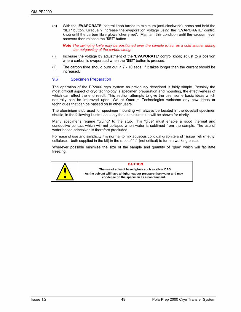
OM-PP2000
Issue 1.2 49 PolarPrep 2000 Cryo Transfer System
(h) With the 'EVAPORATE' control knob turned to minimum (anti-clockwise), press and hold the 'SET' button. Gradually increase the evaporation voltage using the 'EVAPORATE' control knob until the carbon fibre glows 'cherry red'. Maintain this condition until the vacuum level recovers then release the 'SET' button.
Note The swinging knife may be positioned over the sample to act as a cold shutter during the outgassing of the carbon string.
(i) Increase the voltage by adjustment of the 'EVAPORATE' control knob; adjust to a position where carbon is evaporated when the 'SET' button is pressed.
(ii) The carbon fibre should burn out in 7 - 10 secs. If it takes longer then the current should be increased.
9.6 Specimen Preparation
The operation of the PP2000 cryo system as previously described is fairly simple. Possibly the most difficult aspect of cryo technology is specimen preparation and mounting, the effectiveness of which can effect the end result. This section attempts to give the user some basic ideas which naturally can be improved upon. We at Quorum Technologies welcome any new ideas or techniques that can be passed on to other users.
The aluminium stub used for specimen mounting will always be located in the dovetail specimen shuttle, in the following illustrations only the aluminium stub will be shown for clarity.
Many specimens require "gluing" to the stub. This "glue" must enable a good thermal and conductive contact which will not collapse when water is sublimed from the sample. The use of water based adhesives is therefore precluded.
For ease of use and simplicity it is normal to mix aqueous colloidal graphite and Tissue Tek (methyl cellulose – both supplied in the kit) in the ratio of 1:1 (not critical) to form a working paste.
Wherever possible minimise the size of the sample and quantity of "glue" which will facilitate freezing.
CAUTION The use of solvent based glues such as silver DAG.
As the solvent will have a higher vapour pressure than water and may condense on the specimen as a contaminant.
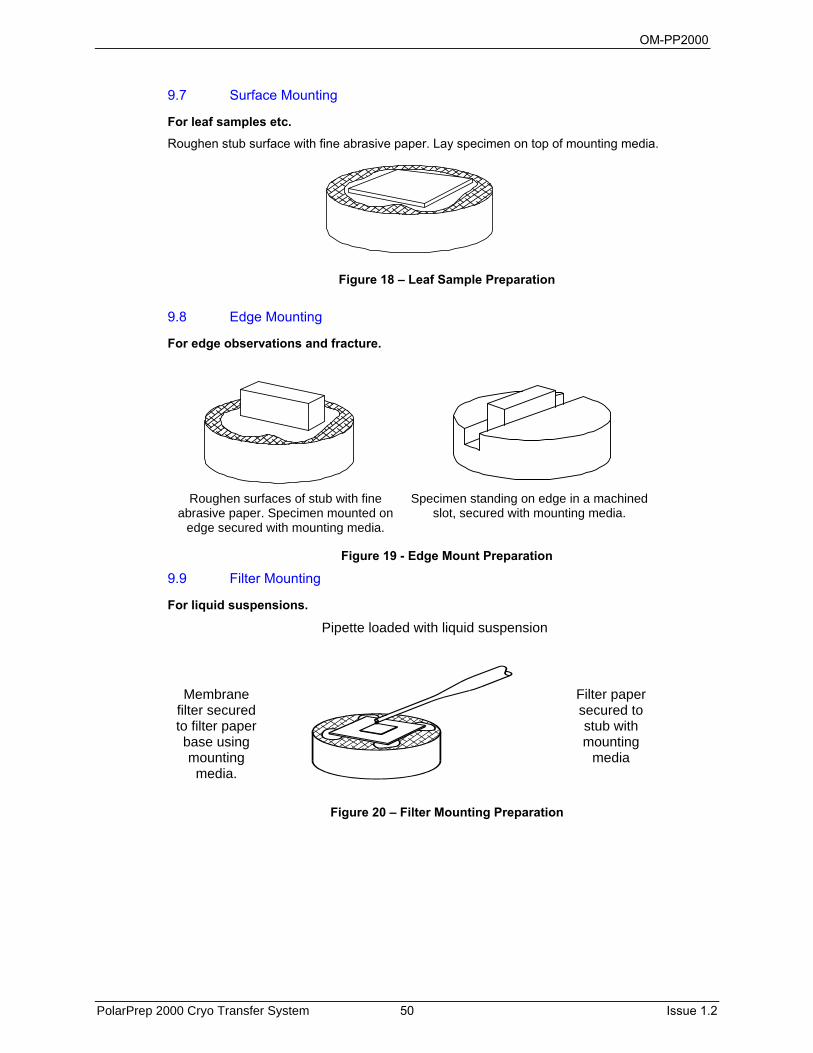
OM-PP2000
PolarPrep 2000 Cryo Transfer System 50 Issue 1.2
9.7 Surface Mounting
For leaf samples etc.
Roughen stub surface with fine abrasive paper. Lay specimen on top of mounting media.
Figure 18 – Leaf Sample Preparation
9.8 Edge Mounting
For edge observations and fracture.
Roughen surfaces of stub with fine abrasive paper. Specimen mounted on
edge secured with mounting media.
Specimen standing on edge in a machined slot, secured with mounting media.
Figure 19 - Edge Mount Preparation
9.9 Filter Mounting
For liquid suspensions.
Pipette loaded with liquid suspension
Membrane filter secured to filter paper base using mounting
media.
Filter paper secured to stub with mounting
media
Figure 20 – Filter Mounting Preparation
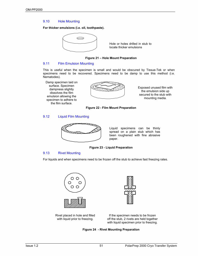
OM-PP2000
Issue 1.2 51 PolarPrep 2000 Cryo Transfer System
9.10 Hole Mounting
For thicker emulsions (i.e. oil, toothpaste).
Hole or holes drilled in stub to locate thicker emulsions
Figure 21 – Hole Mount Preparation
9.11 Film Emulsion Mounting
This is useful when the specimen is small and would be obscured by Tissue-Tek or when specimens need to be recovered. Specimens need to be damp to use this method (i.e. Nematodes).
Damp specimen laid on surface. Specimen dampness slightly dissolves the film
emulsion allowing the specimen to adhere to
the film surface.
Exposed unused film with the emulsion side up
secured to the stub with mounting media.
Figure 22 - Film Mount Preparation
9.12 Liquid Film Mounting
Liquid specimens can be thinly spread on a plain stub which has been roughened with fine abrasive paper.
Figure 23 - Liquid Preparation
9.13 Rivet Mounting
For liquids and when specimens need to be frozen off the stub to achieve fast freezing rates.
Rivet placed in hole and filled with liquid prior to freezing.
If the specimen needs to be frozen off the stub, 2 rivets are held together with liquid specimen prior to freezing.
Figure 24 - Rivet Mounting Preparation
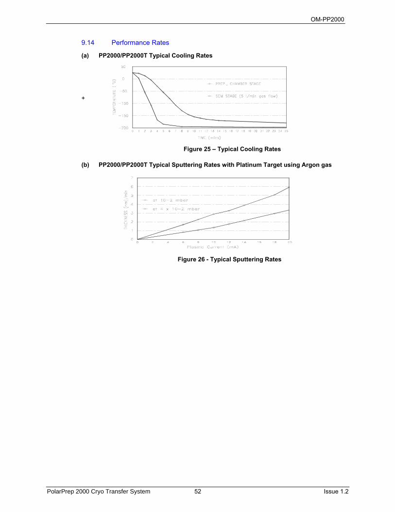
OM-PP2000
PolarPrep 2000 Cryo Transfer System 52 Issue 1.2
9.14 Performance Rates
(a) PP2000/PP2000T Typical Cooling Rates
+
(b) PP2000/PP2000T Typical Sputtering Rates with Platinum Target using Argon gas
Figure 25 – Typical Cooling Rates
Figure 26 - Typical Sputtering Rates
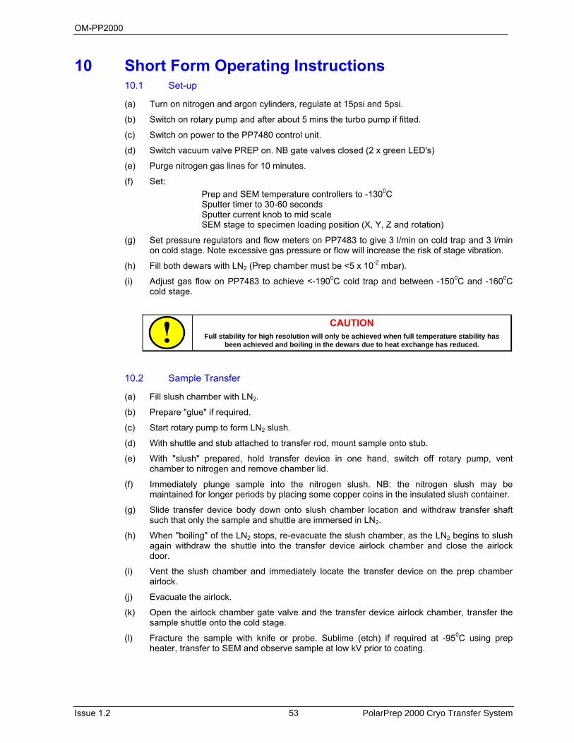
OM-PP2000
Issue 1.2 53 PolarPrep 2000 Cryo Transfer System
10 Short Form Operating Instructions 10.1 Set-up
(a) Turn on nitrogen and argon cylinders, regulate at 15psi and 5psi.
(b) Switch on rotary pump and after about 5 mins the turbo pump if fitted.
(c) Switch on power to the PP7480 control unit.
(d) Switch vacuum valve PREP on. NB gate valves closed (2 x green LED's)
(e) Purge nitrogen gas lines for 10 minutes.
(f) Set: Prep and SEM temperature controllers to -1300C
Sputter timer to 30-60 seconds Sputter current knob to mid scale SEM stage to specimen loading position (X, Y, Z and rotation)
(g) Set pressure regulators and flow meters on PP7483 to give 3 l/min on cold trap and 3 l/min on cold stage. Note excessive gas pressure or flow will increase the risk of stage vibration.
(h) Fill both dewars with LN2 (Prep chamber must be <5 x 10⁻² mbar).
(i) Adjust gas flow on PP7483 to achieve <-1900C cold trap and between -1500C and -1600C cold stage.
CAUTION Full stability for high resolution will only be achieved when full temperature stability has
been achieved and boiling in the dewars due to heat exchange has reduced.
10.2 Sample Transfer
(a) Fill slush chamber with LN2.
(b) Prepare "glue" if required.
(c) Start rotary pump to form LN2 slush.
(d) With shuttle and stub attached to transfer rod, mount sample onto stub.
(e) With "slush" prepared, hold transfer device in one hand, switch off rotary pump, vent chamber to nitrogen and remove chamber lid.
(f) Immediately plunge sample into the nitrogen slush. NB: the nitrogen slush may be maintained for longer periods by placing some copper coins in the insulated slush container.
(g) Slide transfer device body down onto slush chamber location and withdraw transfer shaft such that only the sample and shuttle are immersed in LN2.
(h) When "boiling" of the LN2 stops, re-evacuate the slush chamber, as the LN2 begins to slush again withdraw the shuttle into the transfer device airlock chamber and close the airlock door.
(i) Vent the slush chamber and immediately locate the transfer device on the prep chamber airlock.
(j) Evacuate the airlock.
(k) Open the airlock chamber gate valve and the transfer device airlock chamber, transfer the sample shuttle onto the cold stage.
(l) Fracture the sample with knife or probe. Sublime (etch) if required at -950C using prep heater, transfer to SEM and observe sample at low kV prior to coating.
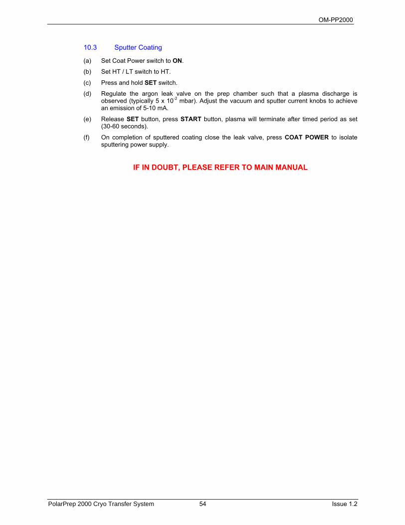
OM-PP2000
PolarPrep 2000 Cryo Transfer System 54 Issue 1.2
10.3 Sputter Coating
(a) Set Coat Power switch to ON.
(b) Set HT / LT switch to HT.
(c) Press and hold SET switch.
(d) Regulate the argon leak valve on the prep chamber such that a plasma discharge is observed (typically 5 x 10⁻² mbar). Adjust the vacuum and sputter current knobs to achieve an emission of 5-10 mA.
(e) Release SET button, press START button, plasma will terminate after timed period as set (30-60 seconds).
(f) On completion of sputtered coating close the leak valve, press COAT POWER to isolate sputtering power supply.
IF IN DOUBT, PLEASE REFER TO MAIN MANUAL
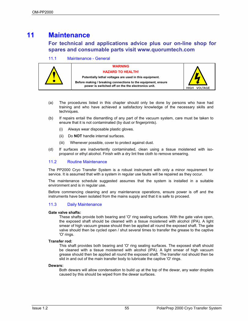
OM-PP2000
Issue 1.2 55 PolarPrep 2000 Cryo Transfer System
11 Maintenance For technical and applications advice plus our on-line shop for spares and consumable parts visit www.quorumtech.com 11.1 Maintenance - General
WARNING HAZARD TO HEALTH!
Potentially lethal voltages are used in this equipment. Before making / breaking connections to the equipment, ensure
power is switched off on the the electronics unit.
(a) The procedures listed in this chapter should only be done by persons who have had training and who have achieved a satisfactory knowledge of the necessary skills and techniques.
(b) If repairs entail the dismantling of any part of the vacuum system, care must be taken to ensure that it is not contaminated (by dust or fingerprints).
(i) Always wear disposable plastic gloves.
(ii) Do NOT handle internal surfaces.
(iii) Whenever possible, cover to protect against dust.
(d) If surfaces are inadvertently contaminated, clean using a tissue moistened with iso-propanol or ethyl alcohol. Finish with a dry lint free cloth to remove smearing.
11.2 Routine Maintenance
The PP2000 Cryo Transfer System is a robust instrument with only a minor requirement for service. It is assumed that with a system in regular use faults will be repaired as they occur.
The maintenance schedule suggested assumes that the system is installed in a suitable environment and is in regular use.
Before commencing cleaning and any maintenance operations, ensure power is off and the instruments have been isolated from the mains supply and that it is safe to proceed.
11.3 Daily Maintenance
Gate valve shafts: These shafts provide both bearing and 'O' ring sealing surfaces. With the gate valve open,
the exposed shaft should be cleaned with a tissue moistened with alcohol (IPA). A light smear of high vacuum grease should then be applied all round the exposed shaft. The gate valve should then be cycled open / shut several times to transfer the grease to the captive 'O' rings.
Transfer rod: This shaft provides both bearing and 'O' ring sealing surfaces. The exposed shaft should
be cleaned with a tissue moistened with alcohol (IPA). A light smear of high vacuum grease should then be applied all round the exposed shaft. The transfer rod should then be slid in and out of the main transfer body to lubricate the captive 'O' rings.
Dewars: Both dewars will allow condensation to build up at the top of the dewar, any water droplets
caused by this should be wiped from the dewar surfaces.

OM-PP2000
PolarPrep 2000 Cryo Transfer System 56 Issue 1.2
11.4 Weekly Maintenance Dependant on usage, the preparation chamber viewing window and lamp will become coated with sputtering target material. The window can be cleaned with a tissue moistened with alcohol (IPA). It is not necessary to remove the actual window, only the front facia plate of the preparation chamber complete with captive window.
(a) Isolate the preparation chamber from the vacuum systems i.e. both gate valves closed and the QSB (if fitted) and PREP valve closed.
(b) Vent the preparation chamber to nitrogen gas using the top plate mounted Vent valve.
(c) Remove the 4 x M5 retaining screws and remove the window assembly.
11.5 Periodical Maintenance
During usage, fracture debris and coating build up will degrade the vacuum performance of the preparation chamber which will then require cleaning as follows:
(a) Remove window assembly as above
(b) Remove preparation chamber base plate, 8 x M5 screws
(c) Remove air lock gate valve assembly 4 x M5 screws
(d) With care and using a stiff brush, dust off any loose coating from the stage area
(e) Using an instrument type vacuum cleaner remove all loose debris from the chamber. Wipe round the accessible surfaces using tissues moistened with alcohol (IPA)
(f) Replace the removed components and evacuate the system
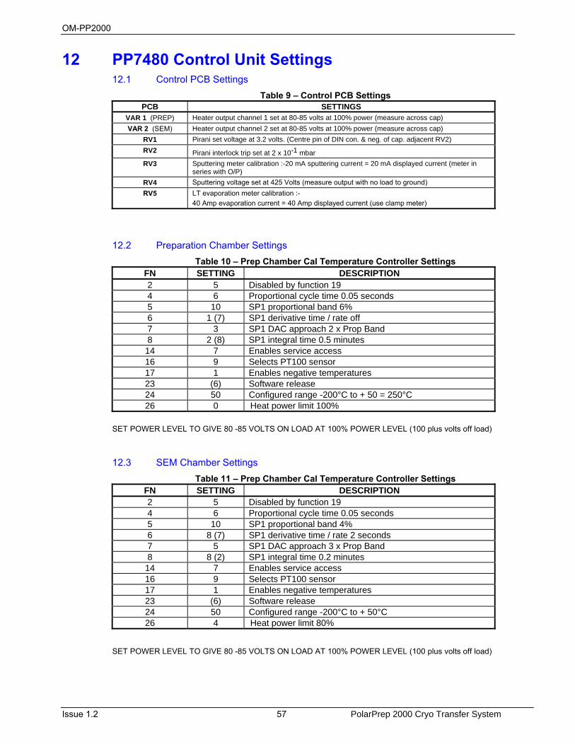
OM-PP2000
Issue 1.2 57 PolarPrep 2000 Cryo Transfer System
12 PP7480 Control Unit Settings 12.1 Control PCB Settings
Table 9 – Control PCB Settings PCB SETTINGS
VAR 1 (PREP) Heater output channel 1 set at 80-85 volts at 100% power (measure across cap)
VAR 2 (SEM) Heater output channel 2 set at 80-85 volts at 100% power (measure across cap)
RV1 Pirani set voltage at 3.2 volts. (Centre pin of DIN con. & neg. of cap. adjacent RV2)
RV2 Pirani interlock trip set at 2 x 10⁻¹ mbar
RV3 Sputtering meter calibration :-20 mA sputtering current = 20 mA displayed current (meter in series with O/P)
RV4 Sputtering voltage set at 425 Volts (measure output with no load to ground) RV5 LT evaporation meter calibration :-
40 Amp evaporation current = 40 Amp displayed current (use clamp meter)
12.2 Preparation Chamber Settings Table 10 – Prep Chamber Cal Temperature Controller Settings
FN SETTING DESCRIPTION2 5 Disabled by function 194 6 Proportional cycle time 0.05 seconds5 10 SP1 proportional band 6%6 1 (7) SP1 derivative time / rate off7 3 SP1 DAC approach 2 x Prop Band8 2 (8) SP1 integral time 0.5 minutes14 7 Enables service access16 9 Selects PT100 sensor17 1 Enables negative temperatures23 (6) Software release24 50 Configured range -200°C to + 50 = 250°C 26 0 Heat power limit 100%
SET POWER LEVEL TO GIVE 80 -85 VOLTS ON LOAD AT 100% POWER LEVEL (100 plus volts off load)
12.3 SEM Chamber Settings Table 11 – Prep Chamber Cal Temperature Controller Settings
FN SETTING DESCRIPTION2 5 Disabled by function 194 6 Proportional cycle time 0.05 seconds5 10 SP1 proportional band 4%6 8 (7) SP1 derivative time / rate 2 seconds7 5 SP1 DAC approach 3 x Prop Band8 8 (2) SP1 integral time 0.2 minutes14 7 Enables service access16 9 Selects PT100 sensor17 1 Enables negative temperatures23 (6) Software release24 50 Configured range -200°C to + 50°C26 4 Heat power limit 80%
SET POWER LEVEL TO GIVE 80 -85 VOLTS ON LOAD AT 100% POWER LEVEL (100 plus volts off load)

OM-PP2000
PolarPrep 2000 Cryo Transfer System 58 Issue 1.2
12.4 Circuit Diagrams
Figure 27 – PP7480 Control Unit Circuit Diagram
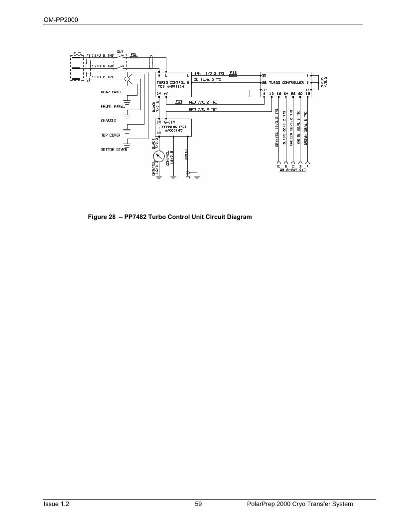
OM-PP2000
Issue 1.2 59 PolarPrep 2000 Cryo Transfer System
Figure 28 – PP7482 Turbo Control Unit Circuit Diagram
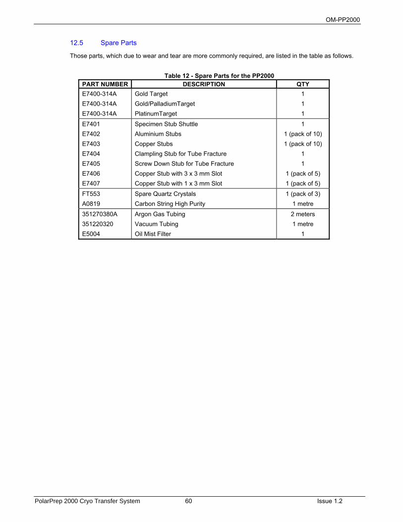
OM-PP2000
PolarPrep 2000 Cryo Transfer System 60 Issue 1.2
12.5 Spare Parts
Those parts, which due to wear and tear are more commonly required, are listed in the table as follows.
Table 12 - Spare Parts for the PP2000
PART NUMBER DESCRIPTION QTY E7400-314A E7400-314A E7400-314A
Gold Target Gold/PalladiumTarget PlatinumTarget
1 1 1
E7401 E7402 E7403 E7404 E7405 E7406 E7407
Specimen Stub Shuttle Aluminium Stubs Copper Stubs Clampling Stub for Tube Fracture Screw Down Stub for Tube Fracture Copper Stub with 3 x 3 mm Slot Copper Stub with 1 x 3 mm Slot
1 1 (pack of 10) 1 (pack of 10)
1 1
1 (pack of 5) 1 (pack of 5)
FT553 A0819
Spare Quartz Crystals Carbon String High Purity
1 (pack of 3) 1 metre
351270380A 351220320 E5004
Argon Gas Tubing Vacuum Tubing Oil Mist Filter
2 meters 1 metre
1

OM-PP2000
Issue 1.2 61 PolarPrep 2000 Cryo Transfer System
13 Fault Finding We hope that you experience the minimum of problems throughout the lifespan of the equipment but inevitably problems may occur. Any known problems associated with this type of instrument will be listed in this section with the possible cause and suggestions to what to do. If problems continue to occur, for example the fuse blows immediately when a new one is fitted, contact the Customer Service Department at Quorum Technologies or your local agent; see section 16 for list of agents
It is assumed that with a system in regular use and that the system was installed in a suitable environment and in regular use, faults will be repaired as they occur.
To maintain the equipment to the best operating conditions a maintenance schedule is suggested as part of a fault prevention programme, a suggested programme has been listed in the maintenance section. The frequency of checking will depend on the usage of the equipment.

OM-PP2000
PolarPrep 2000 Cryo Transfer System 62 Issue 1.2

OM-PP2000
Issue 1.2 63 PolarPrep 2000 Cryo Transfer System
14 Appendix I - Dual slusher option 14.1 Introduction
To facilitate the manipulation and loading of pre-frozen specimens onto the specimen stub an additional slushing chamber is available. The chamber is larger than the standard one and is equipped with a rotatable carrier which allows specimens to be mounted with the stub horizontal and then to turn it to a vertical position to be picked up by the specimen transfer rod.
Figure 29 - Overview of the dual slushing system
Figure 30 - Dual slushing pot
14.2 Using the dual slusher
With the dovetail support in the vertical position, place the specimen dovetail and suitable stub into the support making sure the threaded hole is outermost. Rotate the support to a horizontal position. As with the standard slusher, fill the inner polystyrene cup with liquid nitrogen. Place the Perspex™ lid onto the chamber, turn the three way roughing valve to the large pot position and evacuate using the rotary pump. Once slush has formed, close the roughing valve and vent the chamber. The pre-frozen specimen may now be tipped into the polystyrene cup and using suitable tweezers placed into position
Three way roughing valve
Vent valve
Large slushing pot
Polystyrene cup
Dovetail support
Rotation lever

OM-PP2000
PolarPrep 2000 Cryo Transfer System 64 Issue 1.2
in the stub. Clamp the specimen in place and then rotate the dovetail support in the vertical position. Pre-cool the tip of the transfer rod in the liquid nitrogen in the polystyrene cup and then screw the tip into the upright dovetail. Slide the transfer pot down the transfer rod and position on the pot. Evacuate the chamber using the rotary pump and just before slush forms, retract the transfer rod into the transfer chamber as normal. Close the valve on the transfer chamber, vent the pot and continue as normal.
Figure 31 – Dovetail support horizontal
Figure 32 - Dovetail support vertical
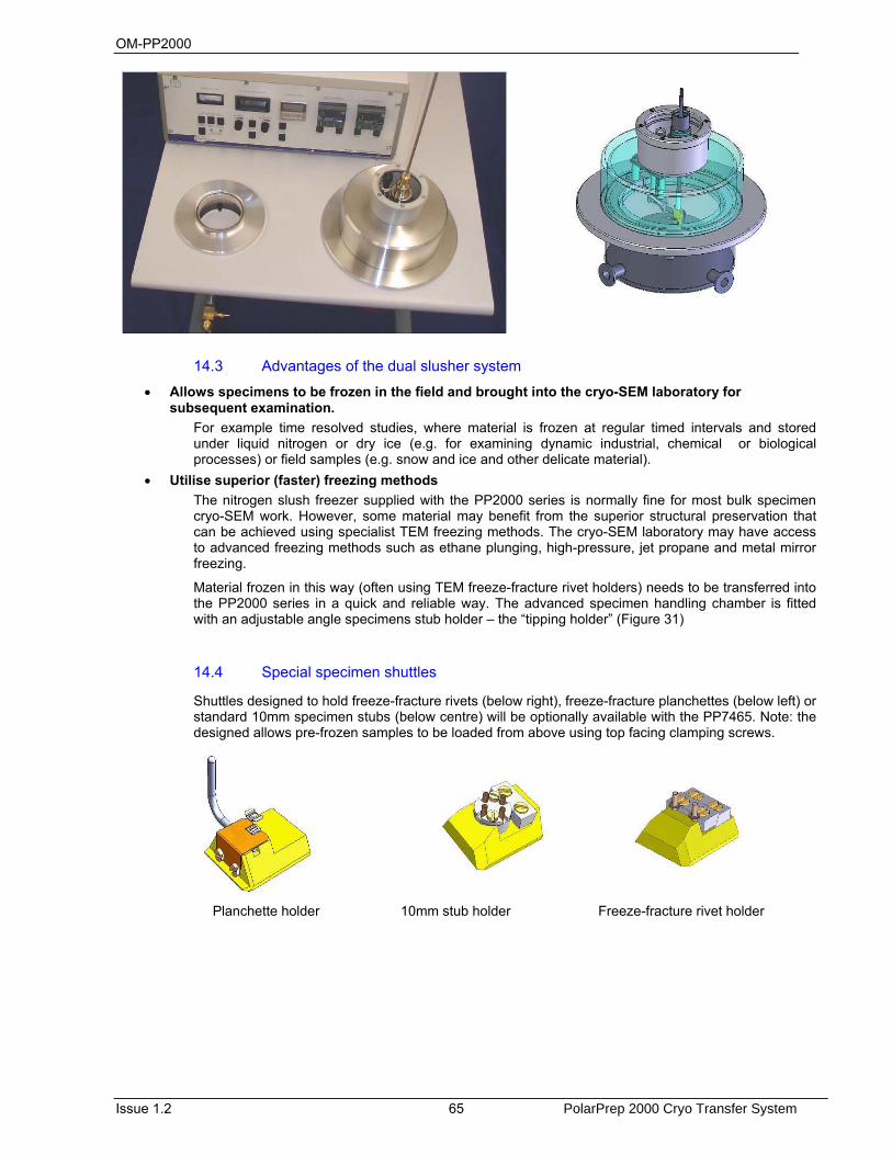
OM-PP2000
Issue 1.2 65 PolarPrep 2000 Cryo Transfer System
14.3 Advantages of the dual slusher system
• Allows specimens to be frozen in the field and brought into the cryo-SEM laboratory for subsequent examination.
For example time resolved studies, where material is frozen at regular timed intervals and stored under liquid nitrogen or dry ice (e.g. for examining dynamic industrial, chemical or biological processes) or field samples (e.g. snow and ice and other delicate material).
• Utilise superior (faster) freezing methods The nitrogen slush freezer supplied with the PP2000 series is normally fine for most bulk specimen cryo-SEM work. However, some material may benefit from the superior structural preservation that can be achieved using specialist TEM freezing methods. The cryo-SEM laboratory may have access to advanced freezing methods such as ethane plunging, high-pressure, jet propane and metal mirror freezing.
Material frozen in this way (often using TEM freeze-fracture rivet holders) needs to be transferred into the PP2000 series in a quick and reliable way. The advanced specimen handling chamber is fitted with an adjustable angle specimens stub holder – the “tipping holder” (Figure 31)
14.4 Special specimen shuttles
Shuttles designed to hold freeze-fracture rivets (below right), freeze-fracture planchettes (below left) or standard 10mm specimen stubs (below centre) will be optionally available with the PP7465. Note: the designed allows pre-frozen samples to be loaded from above using top facing clamping screws.
Planchette holder 10mm stub holder Freeze-fracture rivet holder
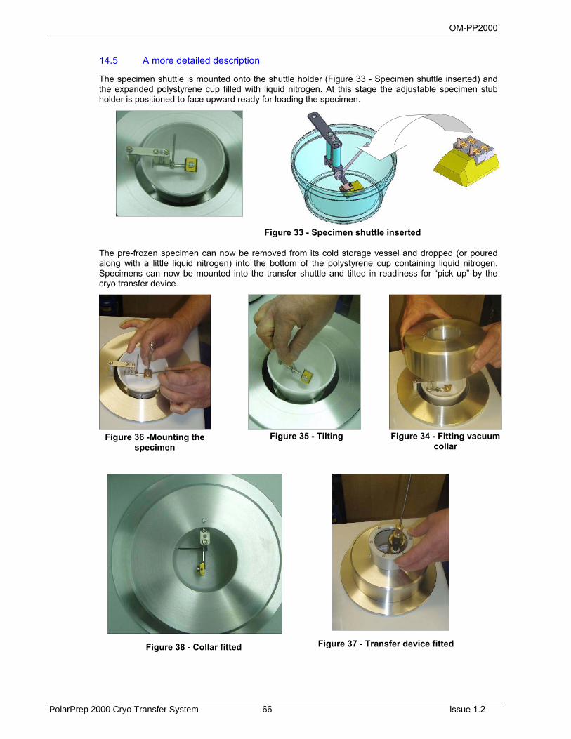
OM-PP2000
PolarPrep 2000 Cryo Transfer System 66 Issue 1.2
14.5 A more detailed description
The specimen shuttle is mounted onto the shuttle holder (Figure 33 - Specimen shuttle inserted) and the expanded polystyrene cup filled with liquid nitrogen. At this stage the adjustable specimen stub holder is positioned to face upward ready for loading the specimen.
The pre-frozen specimen can now be removed from its cold storage vessel and dropped (or poured along with a little liquid nitrogen) into the bottom of the polystyrene cup containing liquid nitrogen. Specimens can now be mounted into the transfer shuttle and tilted in readiness for “pick up” by the cryo transfer device.
Figure 33 - Specimen shuttle inserted
Figure 36 -Mounting the specimen
Figure 35 - Tilting Figure 34 - Fitting vacuum collar
Figure 37 - Transfer device fitted Figure 38 - Collar fitted
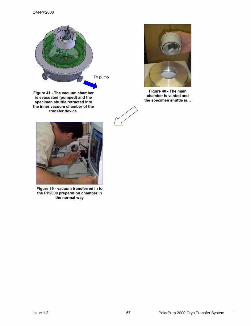
OM-PP2000
Issue 1.2 67 PolarPrep 2000 Cryo Transfer System
To pump
Figure 41 - The vacuum chamber is evacuated (pumped) and the specimen shuttle retracted into
the inner vacuum chamber of the transfer device.
Figure 40 - The main chamber is vented and
the specimen shuttle is…
Figure 39 - vacuum transferred in to the PP2000 preparation chamber in
the normal way

OM-PP2000
PolarPrep 2000 Cryo Transfer System 68 Issue 1.2
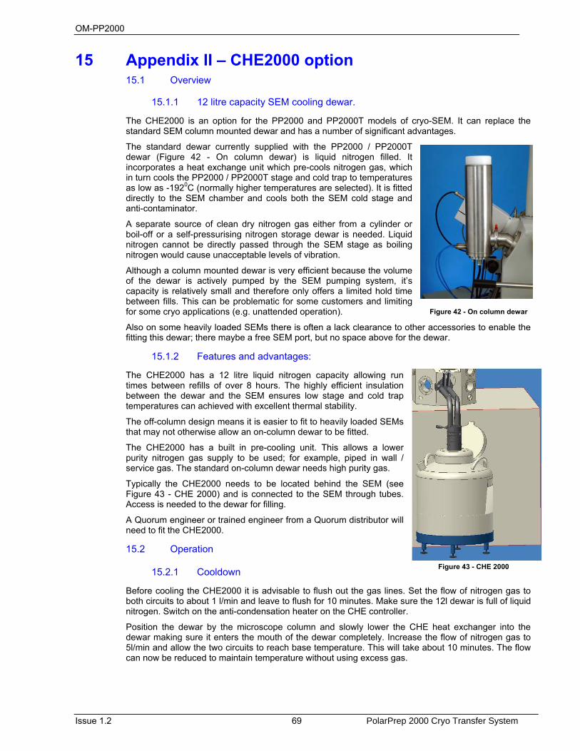
OM-PP2000
Issue 1.2 69 PolarPrep 2000 Cryo Transfer System
15 Appendix II – CHE2000 option 15.1 Overview
15.1.1 12 litre capacity SEM cooling dewar.
The CHE2000 is an option for the PP2000 and PP2000T models of cryo-SEM. It can replace the standard SEM column mounted dewar and has a number of significant advantages.
The standard dewar currently supplied with the PP2000 / PP2000T dewar (Figure 42 - On column dewar) is liquid nitrogen filled. It incorporates a heat exchange unit which pre-cools nitrogen gas, which in turn cools the PP2000 / PP2000T stage and cold trap to temperatures as low as -1920C (normally higher temperatures are selected). It is fitted directly to the SEM chamber and cools both the SEM cold stage and anti-contaminator.
A separate source of clean dry nitrogen gas either from a cylinder or boil-off or a self-pressurising nitrogen storage dewar is needed. Liquid nitrogen cannot be directly passed through the SEM stage as boiling nitrogen would cause unacceptable levels of vibration.
Although a column mounted dewar is very efficient because the volume of the dewar is actively pumped by the SEM pumping system, it’s capacity is relatively small and therefore only offers a limited hold time between fills. This can be problematic for some customers and limiting for some cryo applications (e.g. unattended operation).
Also on some heavily loaded SEMs there is often a lack clearance to other accessories to enable the fitting this dewar; there maybe a free SEM port, but no space above for the dewar.
15.1.2 Features and advantages:
The CHE2000 has a 12 litre liquid nitrogen capacity allowing run times between refills of over 8 hours. The highly efficient insulation between the dewar and the SEM ensures low stage and cold trap temperatures can achieved with excellent thermal stability.
The off-column design means it is easier to fit to heavily loaded SEMs that may not otherwise allow an on-column dewar to be fitted.
The CHE2000 has a built in pre-cooling unit. This allows a lower purity nitrogen gas supply to be used; for example, piped in wall / service gas. The standard on-column dewar needs high purity gas.
Typically the CHE2000 needs to be located behind the SEM (see Figure 43 - CHE 2000) and is connected to the SEM through tubes. Access is needed to the dewar for filling.
A Quorum engineer or trained engineer from a Quorum distributor will need to fit the CHE2000.
15.2 Operation
15.2.1 Cooldown
Before cooling the CHE2000 it is advisable to flush out the gas lines. Set the flow of nitrogen gas to both circuits to about 1 l/min and leave to flush for 10 minutes. Make sure the 12l dewar is full of liquid nitrogen. Switch on the anti-condensation heater on the CHE controller.
Position the dewar by the microscope column and slowly lower the CHE heat exchanger into the dewar making sure it enters the mouth of the dewar completely. Increase the flow of nitrogen gas to 5l/min and allow the two circuits to reach base temperature. This will take about 10 minutes. The flow can now be reduced to maintain temperature without using excess gas.
Figure 42 - On column dewar
Figure 43 - CHE 2000

OM-PP2000
PolarPrep 2000 Cryo Transfer System 70 Issue 1.2
15.2.2 Warm-up
Once work has finished the heat exchanger can be removed from the dewar and the two cooling circuits allowed to warm up. Once at room temperature the gas flow may be stopped and the anti-condensation heater switched off.
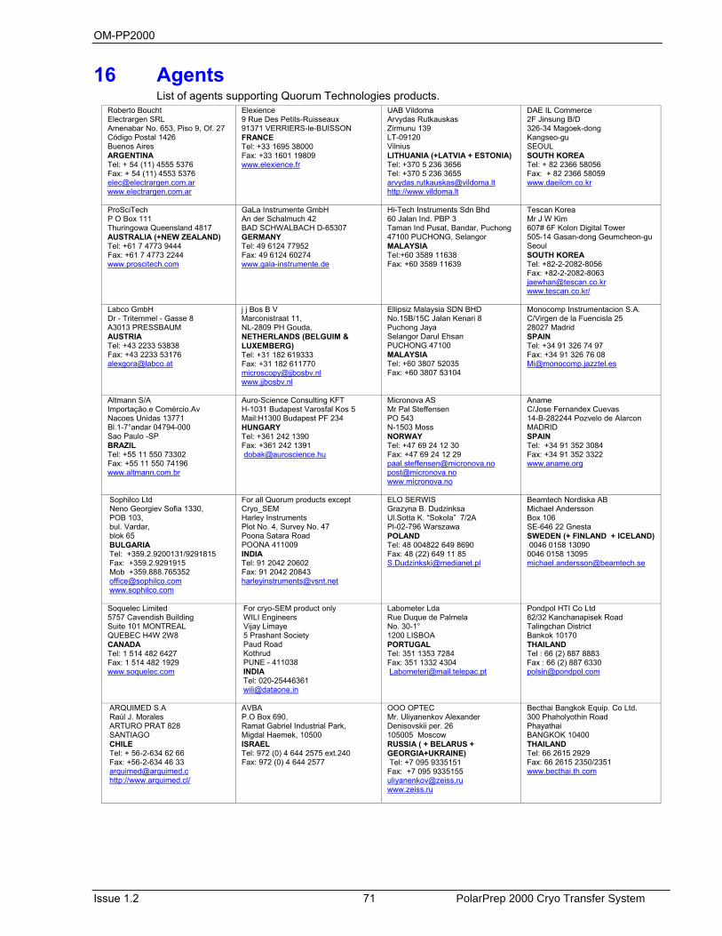
OM-PP2000
Issue 1.2 71 PolarPrep 2000 Cryo Transfer System
16 Agents List of agents supporting Quorum Technologies products.
Roberto Boucht Electrargen SRL Amenabar No. 653, Piso 9, Of. 27 Código Postal 1426 Buenos Aires ARGENTINA Tel: + 54 (11) 4555 5376 Fax: + 54 (11) 4553 5376 [email protected] www.electrargen.com.ar
Elexience 9 Rue Des Petits-Ruisseaux 91371 VERRIERS-le-BUISSON FRANCE Tel: +33 1695 38000 Fax: +33 1601 19809 www.elexience.fr
UAB Vildoma Arvydas Rutkauskas Zirmunu 139 LT-09120 Vilnius LITHUANIA (+LATVIA + ESTONIA) Tel: +370 5 236 3656 Tel: +370 5 236 3655 [email protected] http://www.vildoma.lt
DAE IL Commerce 2F Jinsung B/D 326-34 Magoek-dong Kangseo-gu SEOUL SOUTH KOREA Tel: + 82 2366 58056 Fax: + 82 2366 58059 www.daeilcm.co.kr
ProSciTech P O Box 111 Thuringowa Queensland 4817 AUSTRALIA (+NEW ZEALAND) Tel: +61 7 4773 9444 Fax: +61 7 4773 2244 www.proscitech.com
GaLa Instrumente GmbH An der Schalmuch 42 BAD SCHWALBACH D-65307 GERMANY Tel: 49 6124 77952 Fax: 49 6124 60274 www.gala-instrumente.de
Hi-Tech Instruments Sdn Bhd 60 Jalan Ind. PBP 3 Taman Ind Pusat, Bandar, Puchong 47100 PUCHONG, Selangor MALAYSIA Tel:+60 3589 11638 Fax: +60 3589 11639
Tescan Korea Mr J W Kim 607# 6F Kolon Digital Tower 505-14 Gasan-dong Geumcheon-guSeoul SOUTH KOREA Tel: +82-2-2082-8056 Fax: +82-2-2082-8063 [email protected] www.tescan.co.kr/
Labco GmbH Dr - Tritemmel - Gasse 8 A3013 PRESSBAUM AUSTRIA Tel: +43 2233 53838 Fax: +43 2233 53176 [email protected]
j j Bos B V Marconistraat 11, NL-2809 PH Gouda, NETHERLANDS (BELGUIM & LUXEMBERG) Tel: +31 182 619333 Fax: +31 182 611770 [email protected] www.jjbosbv.nl
Ellipsiz Malaysia SDN BHD No.15B/15C Jalan Kenari 8 Puchong Jaya Selangor Darul Ehsan PUCHONG 47100 MALAYSIA Tel: +60 3807 52035 Fax: +60 3807 53104
Monocomp Instrumentacion S.A. C/Virgen de la Fuencisla 25 28027 Madrid SPAIN Tel: +34 91 326 74 97 Fax: +34 91 326 76 08 [email protected]
Altmann S/A Importação.e Comércio.Av Nacoes Unidas 13771 Bl.1-7°andar 04794-000 Sao Paulo -SP BRAZIL Tel: +55 11 550 73302 Fax: +55 11 550 74196 www.altmann.com.br
Auro-Science Consulting KFT H-1031 Budapest Varosfal Kos 5 Mail:H1300 Budapest PF 234 HUNGARY Tel: +361 242 1390 Fax: +361 242 1391 [email protected]
Micronova AS Mr Pal Steffensen PO 543 N-1503 Moss NORWAY Tel: +47 69 24 12 30 Fax: +47 69 24 12 29 [email protected] [email protected] www.micronova.no
Aname C/Jose Fernandex Cuevas 14-B-282244 Pozvelo de Alarcon MADRID SPAIN Tel: +34 91 352 3084 Fax: +34 91 352 3322 www.aname.org
Sophilco Ltd Neno Georgiev Sofia 1330, POB 103, bul. Vardar, blok 65 BULGARIA Tel: +359.2.9200131/9291815 Fax: +359.2.9291915 Mob +359.888.765352 [email protected] www.sophilco.com
For all Quorum products except Cryo_SEM Harley Instruments Plot No. 4, Survey No. 47 Poona Satara Road POONA 411009 INDIA Tel: 91 2042 20602 Fax: 91 2042 20843 [email protected]
ELO SERWIS Grazyna B. Dudzinksa Ul.Sotta K. “Sokola” 7/2A Pl-02-796 Warszawa POLAND Tel: 48 004822 649 8690 Fax: 48 (22) 649 11 85 [email protected]
Beamtech Nordiska AB Michael Andersson Box 106 SE-646 22 Gnesta SWEDEN (+ FINLAND + ICELAND) 0046 0158 13090 0046 0158 13095 [email protected]
Soquelec Limited 5757 Cavendish Building Suite 101 MONTREAL QUEBEC H4W 2W8 CANADA Tel: 1 514 482 6427 Fax: 1 514 482 1929 www.soquelec.com
For cryo-SEM product only WILI Engineers Vijay Limaye 5 Prashant Society Paud Road Kothrud PUNE - 411038 INDIA Tel: 020-25446361 [email protected]
Labometer Lda Rue Duque de Palmela No. 30-1° 1200 LISBOA PORTUGAL Tel: 351 1353 7284 Fax: 351 1332 4304 [email protected]
Pondpol HTI Co Ltd 82/32 Kanchanapisek Road Talingchan District Bankok 10170 THAILAND Tel : 66 (2) 887 8883 Fax : 66 (2) 887 6330 [email protected]
ARQUIMED S.A Raúl J. Morales ARTURO PRAT 828 SANTIAGO CHILE Tel: + 56-2-634 62 66 Fax: +56-2-634 46 33 [email protected] http://www.arquimed.cl/
AVBA P.O Box 690, Ramat Gabriel Industrial Park, Migdal Haemek, 10500 ISRAEL Tel: 972 (0) 4 644 2575 ext.240 Fax: 972 (0) 4 644 2577
OOO OPTEC Mr. Uliyanenkov Alexander Denisovskii per. 26 105005 Moscow RUSSIA ( + BELARUS + GEORGIA+UKRAINE) Tel: +7 095 9335151 Fax: +7 095 9335155 [email protected] www.zeiss.ru
Becthai Bangkok Equip. Co Ltd. 300 Phaholyothin Road Phayathai BANGKOK 10400 THAILAND Tel: 66 2615 2929 Fax: 66 2615 2350/2351 www.becthai.th.com
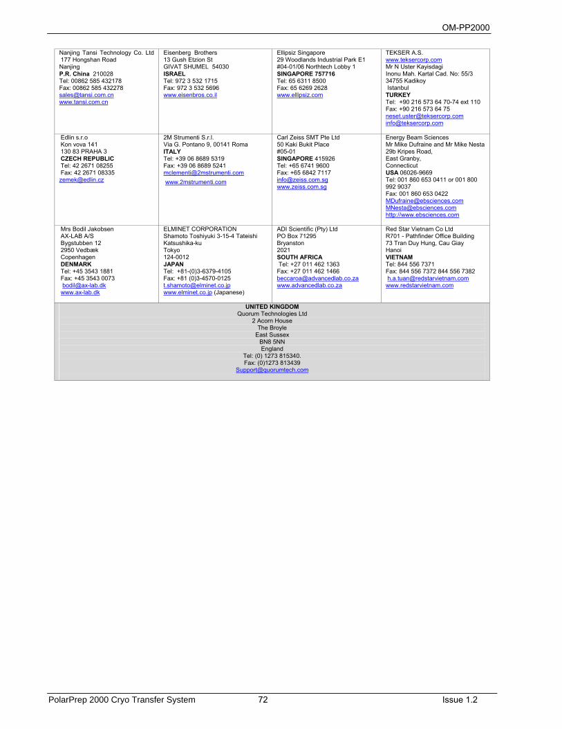
OM-PP2000
PolarPrep 2000 Cryo Transfer System 72 Issue 1.2
Nanjing Tansi Technology Co. Ltd 177 Hongshan Road Nanjing P.R. China 210028 Tel: 00862 585 432178 Fax: 00862 585 432278 [email protected] www.tansi.com.cn
Eisenberg Brothers 13 Gush Etzion St GIVAT SHUMEL 54030 ISRAEL Tel: 972 3 532 1715 Fax: 972 3 532 5696 www.eisenbros.co.il
Ellipsiz Singapore 29 Woodlands Industrial Park E1 #04-01/06 Northtech Lobby 1 SINGAPORE 757716 Tel: 65 6311 8500 Fax: 65 6269 2628 www.ellipsiz.com
TEKSER A.S. www.teksercorp.com Mr N Uster Kayisdagi Inonu Mah. Kartal Cad. No: 55/3 34755 Kadikoy Istanbul TURKEY Tel: +90 216 573 64 70-74 ext 110 Fax: +90 216 573 64 75 [email protected] [email protected]
Edlin s.r.o Kon vova 141 130 83 PRAHA 3 CZECH REPUBLIC Tel: 42 2671 08255 Fax: 42 2671 08335 [email protected]
2M Strumenti S.r.l. Via G. Pontano 9, 00141 Roma ITALY Tel: +39 06 8689 5319 Fax: +39 06 8689 5241 [email protected] www.2mstrumenti.com
Carl Zeiss SMT Pte Ltd 50 Kaki Bukit Place #05-01 SINGAPORE 415926 Tel: +65 6741 9600 Fax: +65 6842 7117 [email protected] www.zeiss.com.sg
Energy Beam Sciences Mr Mike Dufraine and Mr Mike Nesta 29b Kripes Road, East Granby, Connecticut USA 06026-9669 Tel: 001 860 653 0411 or 001 800 992 9037 Fax: 001 860 653 0422 [email protected] [email protected] http://www.ebsciences.com
Mrs Bodil Jakobsen AX-LAB A/S Bygstubben 12 2950 Vedbæk Copenhagen DENMARK Tel: +45 3543 1881 Fax: +45 3543 0073 [email protected] www.ax-lab.dk
ELMINET CORPORATION Shamoto Toshiyuki 3-15-4 Tateishi Katsushika-ku Tokyo 124-0012 JAPAN Tel: +81-(0)3-6379-4105 Fax: +81 (0)3-4570-0125 [email protected] www.elminet.co.jp (Japanese)
ADI Scientific (Pty) Ltd PO Box 71295 Bryanston 2021 SOUTH AFRICA Tel: +27 011 462 1363 Fax: +27 011 462 1466 [email protected] www.advancedlab.co.za
Red Star Vietnam Co Ltd R701 - Pathfinder Office Building 73 Tran Duy Hung, Cau Giay Hanoi VIETNAM Tel: 844 556 7371 Fax: 844 556 7372 844 556 7382 [email protected] www.redstarvietnam.com
UNITED KINGDOM Quorum Technologies Ltd
2 Acorn House The Broyle
East Sussex BN8 5NN England
Tel: (0) 1273 815340. Fax: (0)1273 813439
OM-PP2000
Issue 1.2 73 PolarPrep 2000 Cryo Transfer System
17 Index A
Argon gas, 35
C CHE2000, 69 Circuit Diagrams, 58 Compressed Air, 13 Conformity, 9 Connections, 39 Consumables, 20 Cooling Rates, 52 COSHH, 9 Cryo preparation, 21 Cryo SEM, 21
D Disclaimer, 11 Dual slusher, 63
E Edge Mounting, 50 electric shock, 11 emulsions, 51 Evaporation, 48
F Fault Finding, 61 Film Mount Preparation, 51 flowmeter, 40
G Good Working Practices, 14
H Hazard Labels used on Equipment, 11 Hazard Signal Words, 11 Hazard Signals and Signs, 11 Hazard to Operator, 12 Hazardous Gases, 13 Hazardous Materials, 13 Health and Safety, 9 HSC100, 75
I Installation, 35 Instrument Functionality Signs, 12 International Warning Symbols, 12 Isopropanol, 13
L leaf samples, 50 Liquid nitrogen, 35
Liquid Nitrogen, 13 liquid nitrogen slusher, 31 liquid suspensions, 50
M mains electricity supply, 35 Maintenance, 55
N Nitrogen gas, 35 nitrogen 'slush', 45 Nitrogen, Argon and Helium Gas Supplies, 13
O Operators and Service Engineers, 11 Optional Components, 19
P platinum resistance sensor, 26 preparation chamber, 24
R Return of Goods, 17 Risk Analysis, 13 Rivet Mounting, 51
S Safety Policy, 9 sample fracturing devices, 24 Sample Preparation, 25 SEM liquid nitrogen dewar, 26 Set‐up, 53 Spare Parts, 60 Specimen Etching, 47 Specimen Transfer, 47 spillages, 14 Sputtering, 48 sputtering head, 25 Sputtering Rates, 52 Stage cooling, 26 Stage heating, 24
T Technical Specification, 21 transfer device, 24
V Vacuum Pumping Accessory, 20 vibration, 32 viewport, 24
W warranty, 17

OM-PP2000
PolarPrep 2000 Cryo Transfer System 74 Issue 1.2
Warranty Claim, 17
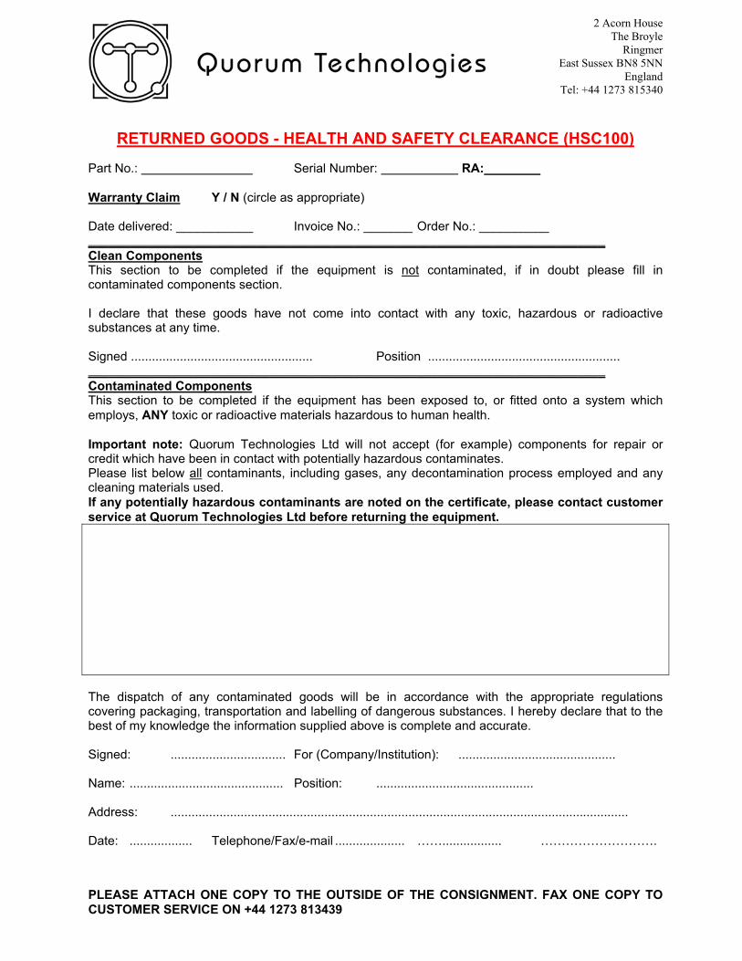
2 Acorn House The Broyle
Ringmer East Sussex BN8 5NN
England Tel: +44 1273 815340
PLEASE ATTACH ONE COPY TO THE OUTSIDE OF THE CONSIGNMENT. FAX ONE COPY TO CUSTOMER SERVICE ON +44 1273 813439
RETURNED GOODS - HEALTH AND SAFETY CLEARANCE (HSC100) Part No.: Serial Number: RA: Warranty Claim Y / N (circle as appropriate) Date delivered: ___________ Invoice No.: _______ Order No.: __________ __________________________________________________________________________ Clean Components This section to be completed if the equipment is not contaminated, if in doubt please fill in contaminated components section. I declare that these goods have not come into contact with any toxic, hazardous or radioactive substances at any time. Signed .................................................... Position ....................................................... __________________________________________________________________________ Contaminated Components This section to be completed if the equipment has been exposed to, or fitted onto a system which employs, ANY toxic or radioactive materials hazardous to human health. Important note: Quorum Technologies Ltd will not accept (for example) components for repair or credit which have been in contact with potentially hazardous contaminates. Please list below all contaminants, including gases, any decontamination process employed and any cleaning materials used. If any potentially hazardous contaminants are noted on the certificate, please contact customer service at Quorum Technologies Ltd before returning the equipment.
The dispatch of any contaminated goods will be in accordance with the appropriate regulations covering packaging, transportation and labelling of dangerous substances. I hereby declare that to the best of my knowledge the information supplied above is complete and accurate. Signed: ................................. For (Company/Institution): ............................................. Name: ............................................ Position: ............................................. Address: ................................................................................................................................... Date: .................. Telephone/Fax/e-mail .................... ……................. ……………………….