Embed Size (px)
DESCRIPTION
Positron. Polarized Electron Footprint at JLab. P. Adderley , J. Clark, J. Dumas ǂ , A. Freyberger , J. Hansknecht , J. Grames , M. Poelker, K. Surles -Law, M. Stutzman, R. Suleiman, E. Voutier ǂ. Thomas Jefferson National Accelerator Facility Newport News, Virginia, USA - PowerPoint PPT Presentation
Citation preview
Polarized Electron Footprint at JLab
P. Adderley, J. Clark, J. Dumasǂ, A. Freyberger, J. Hansknecht, J. Grames, M. Poelker, K. Surles-Law, M. Stutzman, R. Suleiman, E.
Voutierǂ Thomas Jefferson National Accelerator Facility Newport News, Virginia, USA
ǂ Laboratoire de Physique Subatomique et de CosmologieGrenoble, France
Positron
ABC
A B C
Pockels cell
100 keV DCElectron Gun
Two SRF 600 MeV linacs(1497 MHz)
67 MeV injector(1497 MHz)
RF deflectors
Double-sided septum
Wien filter
RF Lasers(499 MHz)
PSpin Precession
Degrees of Freedom
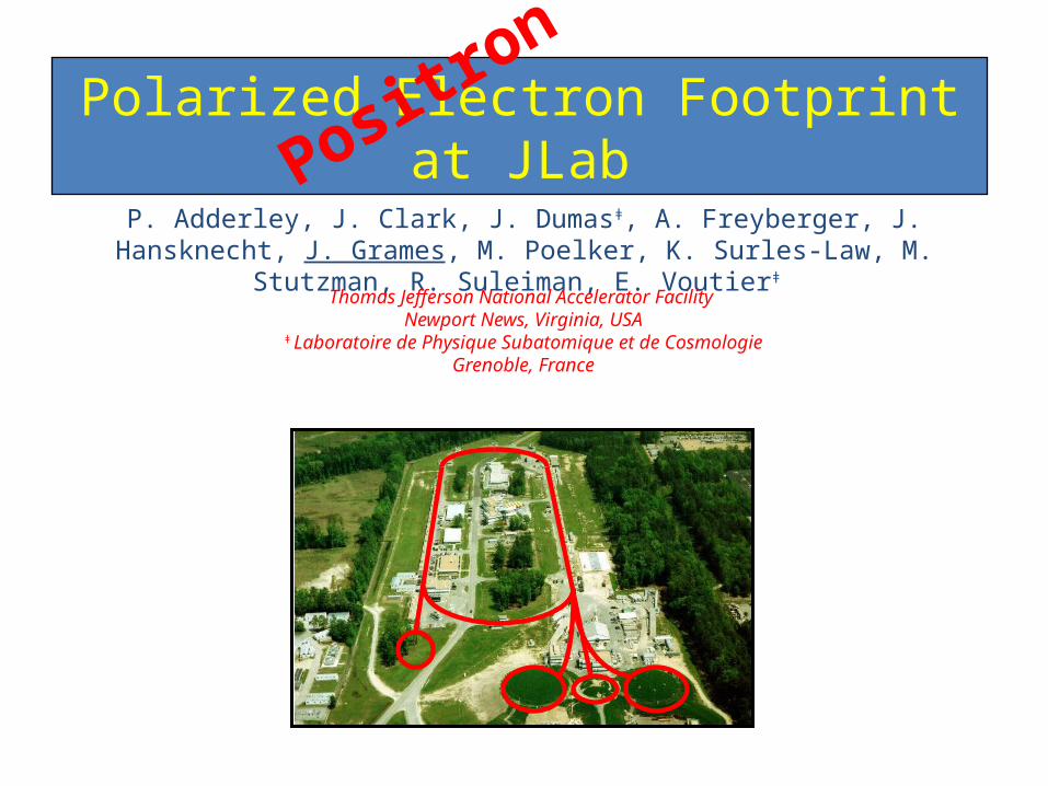
Recirculating SRF LINACsThree Halls; 3x the physics
Continuous Electron Beam Accelerator Facility
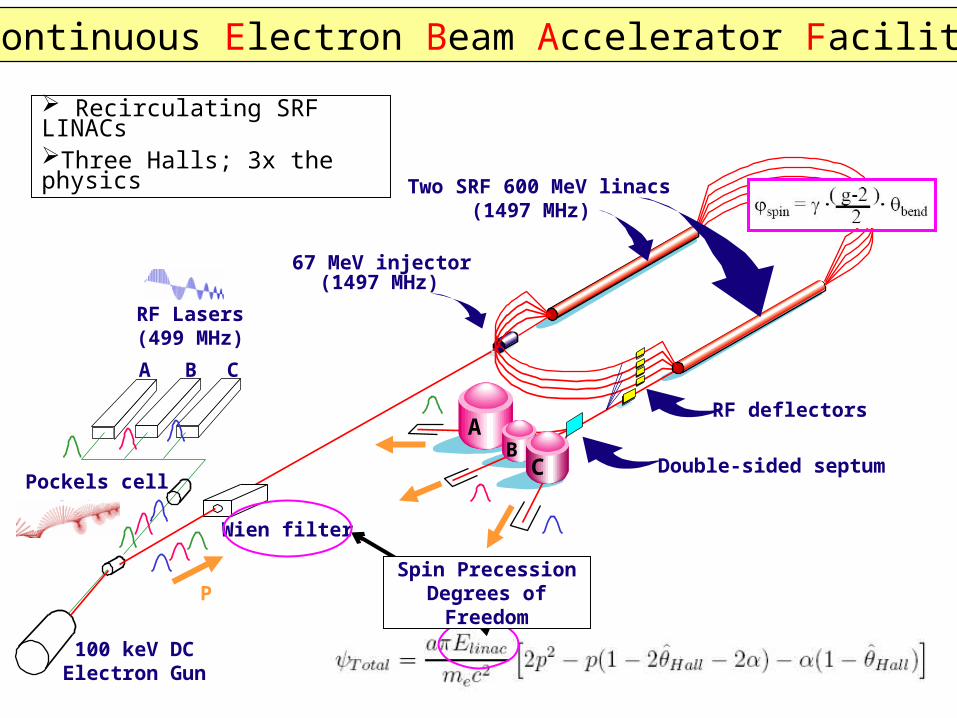
• CEBAF’s first polarized e-beam experiment 1995• Now polarized beam experiments comprise ~ 80% of our physics
program, in fact, we only deliver polarized electrons• All beam originates via photoemission from a strained
superlattice GaAs crystal inside a 100kV DC photogun • Three experimental areas may simultaneously receive:
high polarization (~85%) continuous wave (499 MHz) independent intensity (50 pA to 200 mA) energy selection (6 GeV now, 12 GeV 2012)
What about positron physics ? Lepton charge degree of freedom But, costly endeavor… But, rich e- program keeps us busy…
Everyone Gets Polarized Electrons !
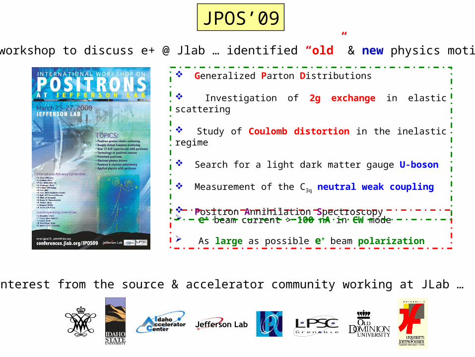
e+ beam current > 100 nA in CW mode As large as possible e+ beam polarization
Generalized Parton Distributions
Investigation of 2g exchange in elastic scattering
Study of Coulomb distortion in the inelastic regime
Search for a light dark matter gauge U-boson
Measurement of the C3q neutral weak coupling
Positron Annihilation Spectroscopy
Recent workshop to discuss e+ @ Jlab … identified “old” & new physics motivations…
New interest from the source & accelerator community working at JLab …
JPOS’09
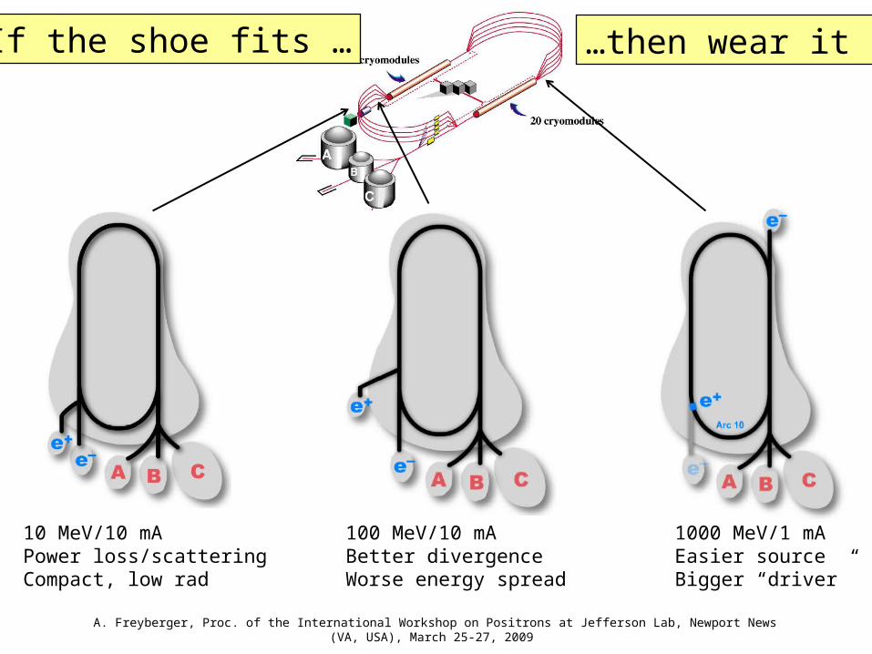
10 MeV/10 mAPower loss/scatteringCompact, low rad
100 MeV/10 mABetter divergenceWorse energy spread
1000 MeV/1 mAEasier sourceBigger “driver”
If the shoe fits … …then wear it !
A. Freyberger, Proc. of the International Workshop on Positrons at Jefferson Lab, Newport News (VA, USA), March 25-27, 2009
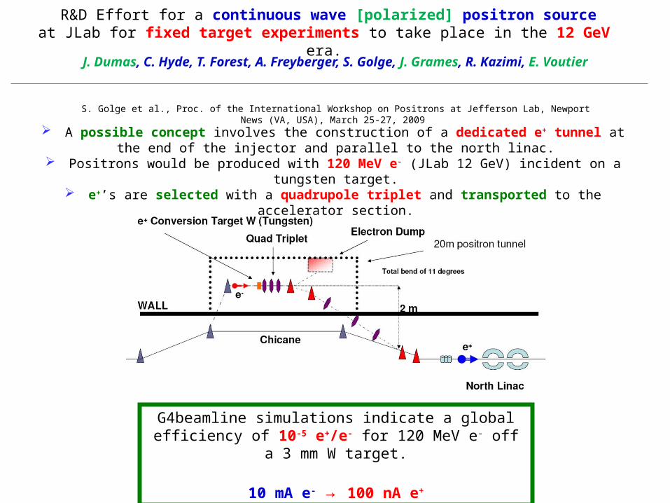
J. Dumas, C. Hyde, T. Forest, A. Freyberger, S. Golge, J. Grames, R. Kazimi, E. Voutier
R&D Effort for a continuous wave [polarized] positron sourceat JLab for fixed target experiments to take place in the 12 GeV era.
A possible concept involves the construction of a dedicated e+ tunnel at the end of the injector and parallel to the north linac.
Positrons would be produced with 120 MeV e- (JLab 12 GeV) incident on a tungsten target.
e+’s are selected with a quadrupole triplet and transported to the accelerator section.
S. Golge et al., Proc. of the International Workshop on Positrons at Jefferson Lab, Newport News (VA, USA), March 25-27, 2009
G4beamline simulations indicate a global efficiency of 10-5 e+/e- for 120 MeV e- off a 3 mm
W target.
10 mA e- → 100 nA e+
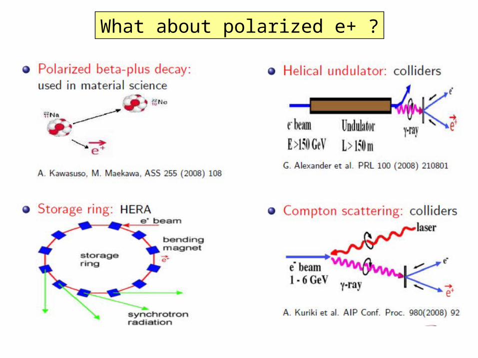
What about polarized e+ ?
e- g e+
e-PairBrem
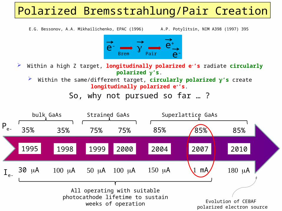
Polarized Bremsstrahlung/Pair Creation
1995 1999 2000 201020041998
30 mA 100 mA 50 mA 100 mA 150 mA 180 mA
35% 35% 75% 75% 85% 85%
2007
1 mA
85%Pe-
Ie-
bulk GaAs Strained GaAs Superlattice GaAs
All operating with suitable photocathode lifetime to sustain weeks
of operation
E.G. Bessonov, A.A. Mikhailichenko, EPAC (1996) A.P. Potylitsin, NIM A398 (1997) 395
Within a high Z target, longitudinally polarized e-’s radiate circularly polarized g’s. Within the same/different target, circularly polarized g’s create longitudinally
polarized e+’s.
Evolution of CEBAF polarized electron source
So, why not pursued so far … ?
Source Property E-166 ExperimentPRL 100, 210801 (2008)
J. Dumas et al. Proc. Spin 2008
Electron beam energy 50 GeV - Undulator 10 MeV - Conversion
Electron beam polarization Unpolarized 85%
Photo Production Synchrotron Bremsstrahlung
Converter Target Tungsten Foil Tungsten Foil
Positron Polarization 80% (measured) 40% (Simulation)
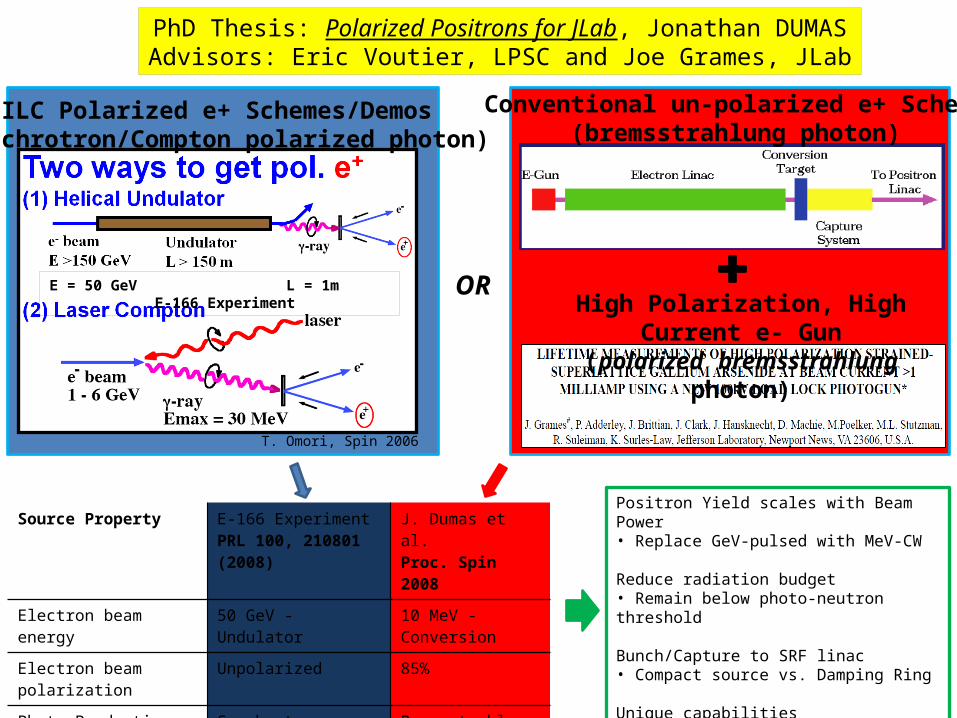
PhD Thesis: Polarized Positrons for JLab, Jonathan DUMASAdvisors: Eric Voutier, LPSC and Joe Grames, JLab
ILC Polarized e+ Schemes/Demos(synchrotron/Compton polarized photon)
Conventional un-polarized e+ Scheme(bremsstrahlung photon)
High Polarization, High Current e- Gun(polarized bremsstrahlung photon)
OR
Positron Yield scales with Beam Power• Replace GeV-pulsed with MeV-CW
Reduce radiation budget• Remain below photo-neutron threshold
Bunch/Capture to SRF linac• Compact source vs. Damping Ring
Unique capabilities• First CW source with helicity reversal
T. Omori, Spin 2006
E = 50 GeV L = 1m E-166 Experiment
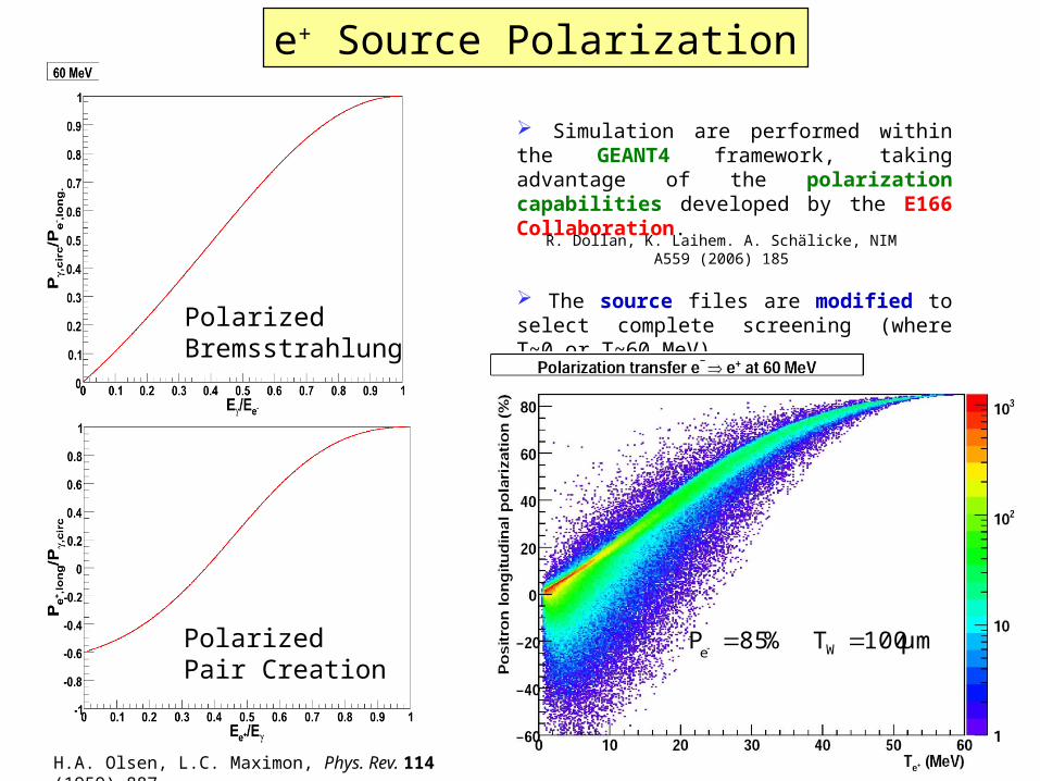
Simulation are performed within the GEANT4 framework, taking advantage of the polarization capabilities developed by the E166 Collaboration.
The source files are modified to select complete screening (where T~0 or T~60 MeV)
R. Dollan, K. Laihem. A. Schälicke, NIM A559 (2006) 185
μm100T%85P We
PolarizedBremsstrahlung
PolarizedPair Creation
H.A. Olsen, L.C. Maximon, Phys. Rev. 114 (1959) 887.
e+ Source Polarization
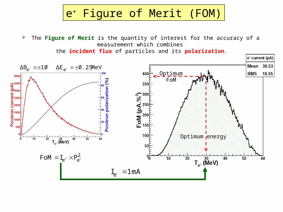
e+ Figure of Merit (FOM) The Figure of Merit is the quantity of interest for the accuracy of a measurement which
combines the incident flux of particles and its polarization.
Optimum energy
OptimumFoM
2ee PIFoM
MeV0.25ΔE10Δθ ee
mA 1Ie
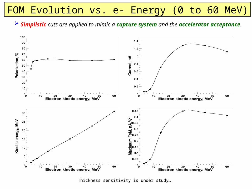
Simplistic cuts are applied to mimic a capture system and the accelerator acceptance.
Thickness sensitivity is under study…
FOM Evolution vs. e- Energy (0 to 60 MeV)
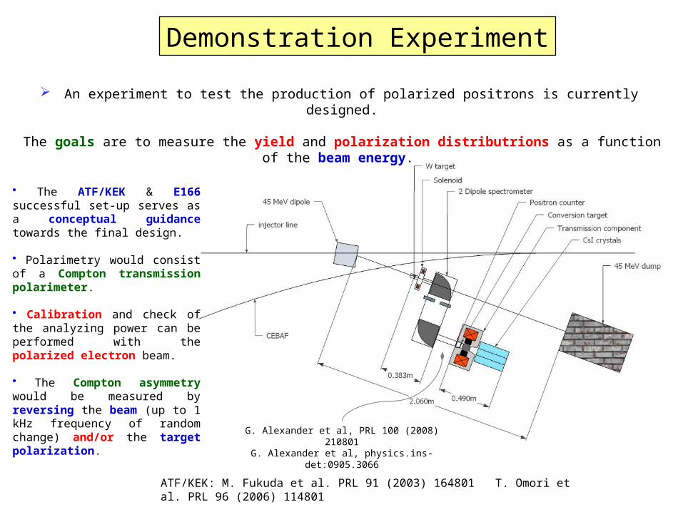
Demonstration Experiment
G. Alexander et al, PRL 100 (2008) 210801G. Alexander et al, physics.ins-
det:0905.3066
An experiment to test the production of polarized positrons is currently designed.
The goals are to measure the yield and polarization distributrions as a function of the beam energy.
• The ATF/KEK & E166 successful set-up serves as a conceptual guidance towards the final design.
• Polarimetry would consist of a Compton transmission polarimeter.
• Calibration and check of the analyzing power can be performed with the polarized electron beam.
• The Compton asymmetry would be measured by reversing the beam (up to 1 kHz frequency of random change) and/or the target polarization.
ATF/KEK: M. Fukuda et al. PRL 91 (2003) 164801 T. Omori et al. PRL 96 (2006) 114801
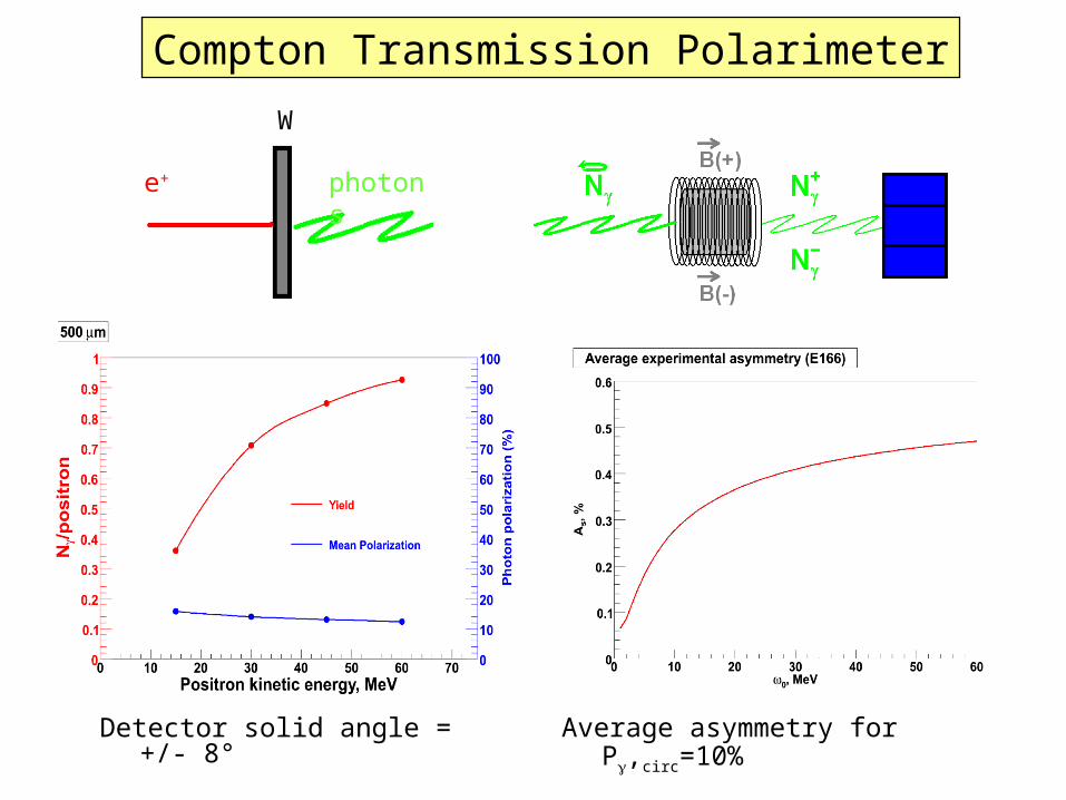
Detector solid angle = +/- 8°
e+
W
photons
Compton Transmission Polarimeter
Pg, circ=100%
Average asymmetry for Pg,circ=10%
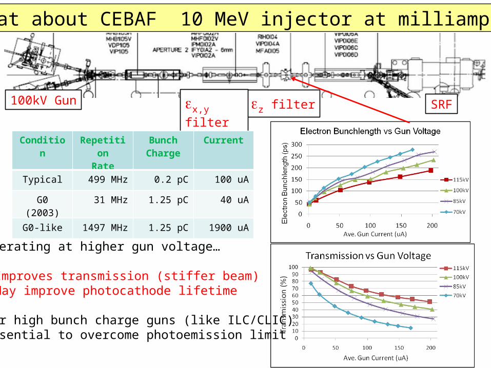
What about CEBAF 10 MeV injector at milliamps?
100kV Gun ez filter SRFex,y filter
Operating at higher gun voltage…
Improves transmission (stiffer beam)May improve photocathode lifetime
For high bunch charge guns (like ILC/CLIC)Essential to overcome photoemission limit
Condition
Repetition
Rate
Bunch Charge
Current
Typical 499 MHz 0.2 pC 100 uA
G0 (2003) 31 MHz 1.25 pC 40 uA
G0-like 1497 MHz 1.25 pC 1900 uA
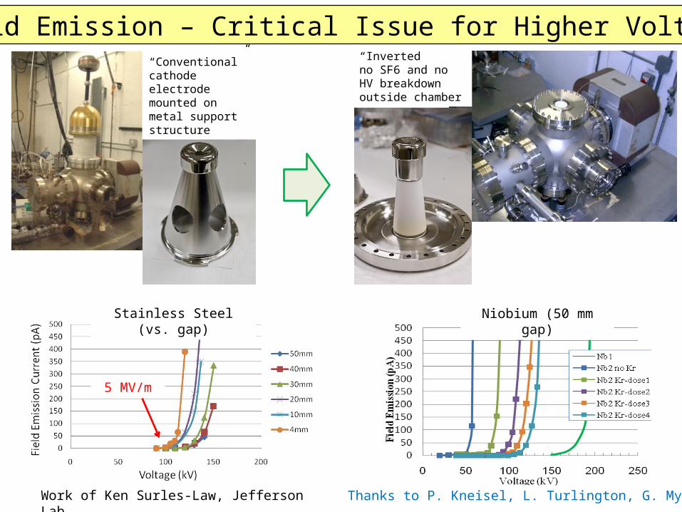
“Inverted” no SF6 and no HV breakdown outside chamber
“Conventional”cathode electrode mounted on metal support structure
Field Emission – Critical Issue for Higher Voltage
Work of Ken Surles-Law, Jefferson Lab Thanks to P. Kneisel, L. Turlington, G. Myneni
Stainless Steel (vs. gap)
Niobium (50 mm gap)
5 MV/m
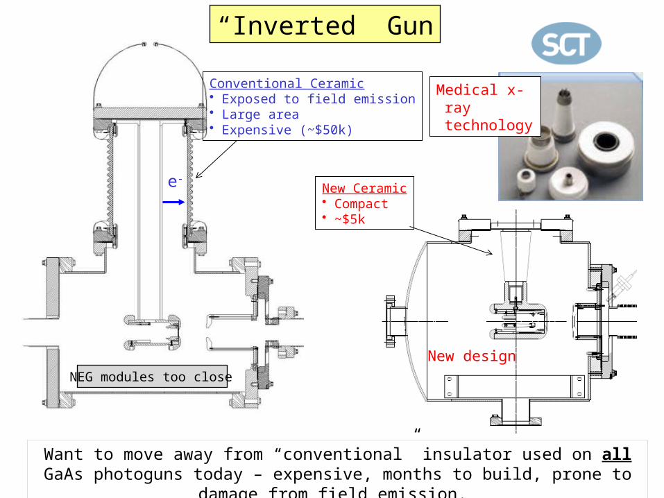
e-
Conventional Ceramic• Exposed to field emission• Large area• Expensive (~$50k)
Medical x-ray technology
New design
New Ceramic• Compact• ~$5k
Want to move away from “conventional” insulator used on all GaAs photoguns today – expensive, months to build, prone to damage from
field emission.
NEG modules too close
“Inverted” Gun
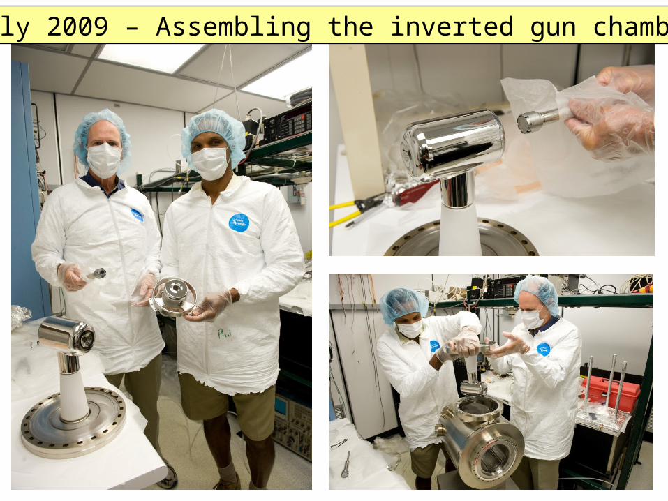
July 2009 – Assembling the inverted gun chamber
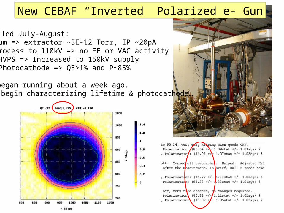
Installed July-August:Vacuum => extractor ~3E-12 Torr, IP ~20pAHV Process to 110kV => no FE or VAC activityNew HVPS => Increased to 150kV supplyNew Photocathode => QE>1% and P~85%
Just began running about a week ago.We’ll begin characterizing lifetime & photocathode…
New CEBAF “Inverted” Polarized e- Gun