Embed Size (px)
Citation preview
Polarization structuresin parhelic circles and in 120° parhelia
Gunther P. Konnen and Jaap Tinbergen
Parhelic circles due to plate-oriented crystals ~hence, with main axes vertical! and 120° parhelia changein position when viewed through a rotating polarizer. The parhelic circle moves vertically; its largestshift is found at an azimuthal distance between 90° and 120° from the Sun. The 120° parhelia move bothvertically and horizontally. The magnitudes of the shifts are between 0.1° and 0.3°, depending on solarelevation. The mechanism is polarization-sensitive internal reflection by prism faces of the ice crystals.We outline the theory and present three visual and one instrumental observation of the displacementsof these halos in polarized light. © 1998 Optical Society of America
OCIS codes: 010.1290, 010.2940, 260.5430.
1. Introduction
The polarization dependence of the refractive index ofice causes inner limbs of refraction halos to bestrongly polarized.1–4 On closer inspection, this ~lin-ear! birefringence appears to result in polarized limbsof reflection halos also. This curiosity of nature, vis-ible as shifting positions of the parhelic circle and the120° parhelia when viewed through a rotating polar-izer, arises when the halo-generating light path in-cludes internal reflection at a prism face.
The mechanism is as follows. Light travelsthrough an ice crystal in one of the polarized normalcrystal modes ~called ordinary and extraordinary! forthat direction of propagation. When light of such anormal mode is reflected at a prism face, the polar-ization after reflection will, in general, not correspondto one of the two normal modes for the new directionof propagation. Consequently, the intensity of theincident ray is redistributed over the two new normalmodes, which results in two reflected rays followingslightly different paths through the crystal. Be-cause the two reflected rays are orthogonally polar-
G. P. Konnen is with the Royal Netherlands Meteorological In-stitute, P.O. Box 201, 3730 AE De Bilt, The Netherlands. J. Tin-bergen is with the University of Leiden and the NetherlandsFoundation for Research in Astronomy, P.O. Box 2, 7990 AA Dwin-geloo, The Netherlands.
Received 6 June 1997; revised manuscript received 16 Septem-ber 1997.
0003-6935y98y091457-08$15.00y0© 1998 Optical Society of America
ized, this leads to a polarization dependence of theposition in the sky of the resulting reflection halo.
The above splitting into two polarized componentsapplies to both partial internal reflection and to totalreflection. This means that the shift of reflection ha-los in polarized light is not limited to the low-intensityray paths of partial reflection, but also occurs in thehigh-intensity ray paths of total reflection. This iswhy the shift can actually be observed in nature.
In this paper, theory and observations of the dis-placements in polarized light of the parhelic circleand the 120° parhelia are described. The calcula-tions outlined in the theoretical section apply specif-ically to ray paths consisting of two refractions andone or two internal reflections. These ray paths pro-vide by far the dominating contribution to the par-helic circle radiance at the azimuth of maximum shiftand to that of the 120° parhelion, respectively.5Therefore the results of the theoretical section applyto parhelic circles and 120° parhelia as they actuallyappear in nature.
2. Theory
A. Polarized Components
The theory of refraction and reflection of light in bi-refringent crystals is described by Szivessy.6 In thissection we summarize his results to the extent thatthey apply to halo polarization.
Ice belongs to the hexagonal crystal class 6mm, soan ice crystal is linearly birefringent and uniaxial.The optic axis of ice coincides with the crystallo-graphic C axis ~the crystal main axis!. The ordinaryindex of refraction no ~>1.31! is 0.0014 smaller7 than
20 March 1998 y Vol. 37, No. 9 y APPLIED OPTICS 1457

Fig. 1. Internal reflection of ~the wave normal of ! the e ray at a prism face ~the ray enters and leaves the crystal through basal faces!.In addition to the plane of incidence and the basal plane ~the plane through the point of reflection and parallel to basal faces of the crystal!,the right-hand diagram shows the planes containing the optic axis and, respectively, the incident ray and the reflected ray. The indexof refraction for an e ray is determined by the angle g and its polarization ~electric-field vibration! is always in the plane defined by theoptic axis and the ray. The angle h defines the polarization angle of the incident e ray with respect to the plane of incidence. Thepolarization angle of the reflected e ray is 2h, which differs from that expected by the Fresnel laws of reflection. As a result, a secondray ~an ordinary one, not shown! of opposite polarization is created at reflection. Its wave normal is also in the plane of incidence, butits angle of reflection differs from the angle of incidence i. Reflection of o rays is analogous to that of e rays. The angle ip is the projectionof i onto the basal plane.
the extraordinary index of refraction ne. An unpo-larized ray of light that enters an ice crystal is splitinto two polarized rays: an ordinary refracted ray ~oray! and an extraordinary ray ~e ray!. The polariza-tion ~direction of vibration of the electric field! of theo ray is perpendicular to the plane defined by the oray and the optic axis; that of the e ray is parallel tothe plane defined by the e ray and the optic axis.The wave normal of the o ray is subject to a refractiveindex of n0; that of the e ray to neff is given by
1neff
2 5sin2 g
no2 1
cos2 g
ne2 , (1)
where g is the angle between the e ray ~wave normal!and the optic axis. Note that n0 , neff # ne. Theangle of refraction of the e ray is defined by Eq. ~1!and Snel’s8,9 law.
The two rays follow different paths through thecrystal. When the e ray is reflected at a crystal faceand the incident polarization is inclined with respectto the plane of incidence, the polarization state of thereflected ray will generally not correspond to that ofan e ray for that direction of propagation ~Fig. 1!. Asa result, the intensity of the incident ray will be dis-tributed between a reflected e ray that follows theusual law of reflection and a newly created o ray.The latter’s path can be found6 from
neff sin i 5 no sin i9 ~e3 o!, (2)
1458 APPLIED OPTICS y Vol. 37, No. 9 y 20 March 1998
where i and i9 are the angles of incidence and reflec-tion, respectively, of the wave normals. For an o raythat is reflected, a similar argument holds, and theangle of reflection i9 of the newly created e ray followsfrom
no sin i 5 neff sin i9 ~o3 e!. (3)
Equations ~2! and ~3! hold for totally reflected rays aswell as for partially ~internally! reflected rays.
New rays are created only during reflection at aprism face ~or at a pyramidal face, which case is notconsidered here!, but never through reflection at abasal face. The reason is that, for basal faces, theoptic axis is always in the plane of incidence, andhence the polarizations of the o ray and the e ray arealways at 90° and 0°, respectively, relative to theplane of incidence.
Further internal reflection at a prism face leads toadditional splitting of the rays. Hence the numberof o rays and e rays that travel through the crystalincreases exponentially with the number of reflec-tions. However, for a crystal that consists of basaland prism faces only, the angle g is the same for all erays and, similarly, the same for all o rays. As theface normal of a basal face is parallel to the optic axis,these two angles g represent the angle of incidence atbasal faces of any e ray and any o ray, respectively.

B. Parhelic Circles
We now consider plate-oriented crystals ~main axesvertical! and the ray path of the parhelic circle thatconsists of entrance at the upper basal face, reflectionat a prism face, and exit at the bottom basal face ~i.e.,132 in Tape’s5 notation of the crystal faces!; this pathproduces by far the main contribution to the circle’sradiance. There are four possible sequences of polar-ization in this path. With the face numbers betweenparentheses, they are
~1!o~3!o~2! ; oo, ~1!e~3!o~2! ; eo,
~1!o~3!e~2! ; oe, ~1!e~3!e~2! ; ee. (4)
The right-hand sides represent a shortened notationthat indicates the consecutive states of the ray whiletraveling through the crystal. In each case, the lastsymbol indicates the state of the emerging ray. Be-cause of the vertical orientation of the optic axes, orays emerging from plate-oriented crystals are hori-zontally polarized and e rays are vertically polarized.
Let hp be the elevation of the parhelic circle andhsun the solar elevation. It then follows from Snel’slaw and from Eqs. ~1!–~3! that, for any azimuth,
hp 5 hsun ~oo, ee paths!,
no cos hp 5 ne cos hsun ~oe path!,
ne cos hp 5 no cos hsun ~eo path!. (5)
Equations ~5! show that idealized parhelic circlesfrom plate-oriented crystals actually consist of threeseparate concentric circles: a middle circle that be-haves as in isotropic crystals ~weakly polarized byFresnel losses only!, a 100% horizontally polarizedupper satellite circle, and a 100% vertically polarizedlower satellite circle.
For parhelic ray paths involving more internal re-flections, Eqs. ~5! remain valid because of the con-stancy of the angles g. On the other hand, a parheliccircle from column-oriented or Parry-oriented crys-tals ~hence, with the main crystal axis horizontal!will not produce a perceptible split, as the internalreflection in the main ray path ~316! takes place at abasal face.
C. Azimuthal Positions of the 120° ParhelionComponents
For the 120° parhelia the most prominent ray path5 is1342 ~Tape’s notation5!, i.e., entrance and exit atbasal faces and internal reflections at two adjacentprism faces ~see Fig. 2, top left!. The horizontal de-flection of rays during a transition from e rays to orays or vice versa can be calculated from Eqs. ~1!–~3!.It can be proved that for plate-oriented crystals theprojected paths of rays on the horizontal ~normal!plane are subject to the following Snel-like laws:
ne sin ip 5 no sin ip9 ~e3 o!,
no sin ip 5 ne sin ip9 ~o3 e!, (6)
where ip is the angle of incidence projected on thehorizontal plane ~which is equivalent to the basalface! and ip9 is the projected angle of reflection.Equations ~6! indicate that Bravais transformationsof neffyno and noyneff yield Bravais refractive indicesneyno and noyne, respectively, which are constants.Consequently there is no solar elevation dependencyin Eqs. ~6!.
The combination of Eqs. ~5! and ~6! allows us tocalculate the splitting of the idealized 120° parhe-lion into polarized components. Figure 2 showsthe result for a fixed crystal position with a sym-metrical light path of ooo rays ~ip 5 60°!. The 120°parhelion is split into seven components: one vir-tually unpolarized central spot at the normal 120°parhelion position and six polarized satellite spotsaround it. Rotation of the crystal about its verticalaxis does not affect the position of the central spotor the elevations of the six satellites, but it doesaffect the azimuths of the latter. Equations ~6!indicate that the azimuths of the eoo, eeo, ooe, andoee spots change monotonically on rotation of thecrystal, but the azimuths of the two remaining sat-ellite spots do not. In fact, for oeo and eoe paths,Eqs. ~6! become identical to those describing deflec-tion of light by a prism of refractive index neyno andnoyne, respectively, superposed on a horizontal de-flection by 120°. Hence, on rotation of the crystal,the azimuthal distance, relative to the central spot,of the oeo and eoe spots passes through a minimum.
Fig. 2. Fine structure of a 120° parhelion due to birefringence.The sequences of ordinary and extraordinary rays in the lightpaths inside the crystal are indicated: e.g., oeo means ordinary–extraordinary–ordinary ray. The polarization is indicated foreach spot. The virtually unpolarized central spot corresponds inposition to that of the 120° parhelion in isotropic crystals. Theazimuthal displacements of the six satellite spots are independentof solar elevation hsun; their vertical displacement h 2 hsun in thefigure corresponds to a solar elevation of 25°. The figure displaysthe situation in which the path of the ooo ray is symmetrical withrespect to the crystal hexagon ~projected angles of incidence of 60°for both prism faces!. Rotation of the crystal about its verticalaxis causes a change in azimuthal position of the six satellites;their directions are indicated ~dashed arrows!. The inset depictsthe effect of solar-disk smearing of the spots.
20 March 1998 y Vol. 37, No. 9 y APPLIED OPTICS 1459

This minimum occurs for a symmetrical light path,in which case ip at the first reflection and ip9 at thesecond reflection are equal.
D. Intensities
The intensities of the internally reflected rays can becalculated with Szivessy’s formulas for the amplituderatios of reflected and transmitted light.6 For a bi-refringence as small as that of ice they approximatethe Fresnel formulas. Hence the intensities of thereflected rays can be calculated efficiently from theFresnel formulas with the aid of Mueller calculus,10
considering the sequence: incoming totally linearlypolarized light in one of the normal modes, ~total!reflection, and decomposition of the new state of po-larization into the two normal modes for the directionof propagation after reflection. The calculationyields four coefficients of reflection R, each of themconditional on the mode of the incoming ray ~e or oray! and on the mode of the reflected ray that onewishes to consider ~e or o ray!. We denote thesecoefficients by Ro3e, Ro3o, Re3o, and Re3e, where thefirst subscript indicates the mode of the incoming rayand the second the mode of the reflected ray underconsideration. Thus Ro3e is the intensity of a re-flected e ray created from an incident o ray of unitintensity, and so on.
For a prism face, the polarization angle h of theincident e ray ~see Fig. 1! relates to g and the angle ofincidence, projected on a basal plane ip, by
tan ip 5 tan h cos g. (7)
This leads to the following expressions for the fourreflection coefficients R for total reflection at a prismface:
Ro3e 5 Re3o 5sin2~2ip!cos2 g
1 2 ~1 1 1yn2!cos2 ip sin2 g,
Ro3o 5 Re3e 5 1 2 Ro3e, (8)
where n is the refractive index of ice. For plateorientation and the entrance of light at a basal face~the case we consider here!, g relates by Snel’s lawto hsun:
cos hsun 5 n sin g. (9)
For the parhelic circle, ip relates directly to the azi-muth Az with respect to the Sun by
Az 5 180° 2 2ip. (10)
Before and after the internal reflection, the ~132!rays that generate the parhelic circle cross a basalface. The transmission coefficients T can be ob-tained from the usual Fresnel formulas for refrac-tion. For extraordinary rays T is the coefficient forvertically polarized light, and for ordinary rays T is
1460 APPLIED OPTICS y Vol. 37, No. 9 y 20 March 1998
the coefficient of horizontally polarized light, sothat
Te~basal face! 5 1 2sin2~90° 2 hsun 2 g!
sin2~90° 2 hsun 1 g!,
To~basal face! 5 1 2tan2~90° 2 hsun 2 g!
tan2~90° 2 hsun 1 g!. (11)
The transmission coefficient of a ray through thewhole crystal is then given by TRT; the indices of Rand T depend on the polarization sequence. Thedistribution of the radiance as a function of azimuthover the three components of the parhelic circle isobtained by normalization of each product TRT withthe sum over all components, which is
Te Re3oTo 1 Te Re3eTe 1 To Ro3oTo 1 To Ro3eTe
5 Te2 1 To
2 2 ~Te 2 To!2Ro3e > Te
2 1 To2. (12)
This leads to the following relative radiances of thethree parhelic circles:
upper and lower components ~eo, oe paths!
5Te To
Te2 1 To
2 Ro3e > 1y2Ro3e,
middle component ~ee 1 oo path! > 1 2 Ro3e. (13)
Figure 3 shows, for hsun 5 35°, the relative radi-ances as a function of azimuth. The middle compo-nent radiance is close to zero near an azimuth of 108°.A similar minimum appears for other solar eleva-tions. The azimuth of this minimum decreases withsolar elevation, but always remains between 90° and120°. This implies that the parhelic circle shift in
Fig. 3. Relative radiance of the three parhelic circle componentsas a function of azimuth. The upper component is completelyhorizontally polarized, the lower component is completely verti-cally polarized, and the middle component is virtually unpolarized.At azimuths between 90° and 120°, only the two polarized compo-nents have significant radiance. The plot is for solar elevation35°, but the curves depend only weakly on solar elevation.

polarized light is best observed in the region between90° azimuth and the 120° parhelion.
The relative radiance of the seven constituent 120°parhelion spots is calculated in a similar way to thatof the parhelic circle, the transmission coefficientsthrough the crystal being of the form TRRT. Theresult depends strongly on the position of the crystalwith respect to the incoming light ray: Rotation of aplate-oriented crystal about its vertical axis results instrong variations in the relative radiances. This isdemonstrated in Fig. 4.
E. Broadening of the Radiance Profiles and Smearing
So far we have dealt with the idealized situation ofray optics, a perfect preferential crystal orientation,and a solar diameter of zero. The reality is differ-ent. Diffraction, imperfect crystal orientation, andthe 0.5° solar-disk smearing will broaden the indi-vidual components to such an extent that they al-ways largely overlap ~see also the inset of Fig. 2!.Hence only the limbs of the parhelic circle or the120° parhelion remain noticeably polarized; the ex-istence of polarized constituents can only be in-ferred from an up-and-down shifting of thephenomenon when viewed through a rotating po-larizer and by an additional shifting in azimuth inthe case of the 120° parhelion. As incoherent su-perposition is dominant when smearing leads to therecombination of differently polarized constituents,the directions of the limb polarizations can be di-
Fig. 4. Relative radiance of the seven 120° parhelion componentsas a function of projected angle of incidence ip ~abscissa! of the firstreflection at a prism face. The graphs are arranged according toFig. 2. The relative positions of the spots depend only weakly onip. The middle spot is the unpolarized component; its radiance ismade up of two contributions ~ooo and eee!. The six other spotsare all completely polarized ~Fig. 2!; their radiances consist of onecontribution only ~i.e., eeo, eoo, etc.!. Note that the relative radi-ance patterns of diagonal pairs of spots are equal. At ip 5 60°~dashed vertical lines! the ray path ~neglecting splitting! is sym-metrical with respect to the crystal hexagon. The plots are for asolar elevation of 35°, but for other elevations they are similar.
rectly linked to the polarization of the individualconstituents of these halos.
The observed displacement d of the parhelic circlein polarized light at a given azimuth equals the dif-ference in height between the horizontally and thevertically polarized parhelic circle. The horizontallypolarized circle consists of light from eo and oo paths.Its radiance is centered at a height that correspondsto the radiance-weighted mean position of its twoconstituents ~eo and oo paths! under idealized condi-tions. Similarly, the center of radiance of the par-helic circle observed in vertically polarized lightcorresponds to the radiance-weighted mean height ofthe idealized parhelic circles from oe and ee paths.Using Eqs. ~13! leads to
d 5 2Ro3e@hp~oe! 2 hsun#, (14)
where hp~oe! is given by the second formula of Eqs.~5!. The displacement d is maximal at the azimuthwhere the oo and the ee radiances are minimal; thishappens for an azimuth that is between 90° and 120°.At that azimuth, Ro3e is 0.93 or more, so that damounts to almost twice the separation @Eqs. ~5!#between the middle component of the circle and one ofits satellite circles.
Similarly, the displacement d of the 120° parhelionequals the difference in the radiance-weighted posi-tion of the horizontally ~ooo, eeo, eoo, and oeo paths!and the vertically polarized constituents. In thiscase it makes sense to decompose the displacementinto a vertical one and a horizontal one. Theradiance-weighted position is obtained from the inte-gral over ip, taking into account the geometric shield-
Fig. 5. Displacement d of the parhelic circle and of the 120° par-helion when they are viewed through a rotating polarizer as func-tions of solar elevation. The parhelic circle displacement isvertical, and its value refers to the maximum displacement, whichoccurs at an azimuth between 90° and 120° from the Sun. The120° parhelion shifts in both the horizontal and the vertical direc-tions. The visibility Vis ~right axis! of the displacements is de-fined as the displacement in units of that of the 22° halo.
20 March 1998 y Vol. 37, No. 9 y APPLIED OPTICS 1461

ing factor F of 120° parhelion ray paths in thinregular hexagonal plates, which is
F~ip, g! 5 cos~uip 2 60°u 1 60°!
3 cos~uip 2 60°u 2 60°!sin g tan g. (15)
The displacement in azimuthal degrees, calculatedwith Eqs. ~6!, has to be multiplied by cos hsun toobtain the horizontal displacement d in great-circledegrees. We note that the horizontal 120° parhelionshift is exclusively due to the oeo and the eoe constit-uents, as the radiance-weighted ip-averaged azi-muths of the upper ~eeo 1 eoo! and the lower ~ooe 1oee! spots are both exactly 120°.
Figure 5 shows the dependence of d on solar eleva-tion for the parhelic circle ~maximum value! and the120° parhelion. The right axis relates d directly to ameasure, Vis, of the visibility of the shift, where Vis 51 at d 5 0.106°, which is the 22° halo shift.2,3 Thefigure indicates a larger Vis for the parhelic circledisplacement than for the vertical 120° parhelion dis-placement. However, the visibility of the shift alsodepends on the brightness of the halo and on itsbroadening, and Vis does not take those factors intoaccount.
Smearing, by birefringence, of the parhelic circleand the 120° parhelion radiance may be detectable byan alert observer without the aid of a polarizer. Itshould be apparent by a bluish coloring of the haloedges. The reason is the 10% wavelength depen-dence of the birefringence ne 2 no over the visiblespectrum.7 The birefringence is largest for violet.Both the upper and the lower edges of a parheliccircle should have this bluish color; this ~marginal!coloring is strongest where d is maximal, i.e., some-where between an azimuth of 90° and 120° from theSun. Similarly, the blue coloring of the 120° parhe-lion boundary is strongest in its most polarized parts.The best chance to observe the blue color is in a brightparhelic circle or in a bright 120° parhelion withsharply defined edges. However, whether the coloris in practice visible in nature remains to be checked.
3. Observations
A. Quartz Halos
During the long periods of absence of parhelic circlesor 120° parhelia in the sky, their polarization effectscan be studied by means of a polished piece of quartzcut in the shape of a hexagonal ice-crystal plate.The optic axis has to be perpendicular to the flat ends.Contrary to ice, quartz is optically active, but for g &10° ~hsun * 75°! the optical activity of quartz becomesnegligible11 and the optical properties of ice andquartz are completely analogous. Hence halos gen-erated by the polished quartz crystal behave as ice-crystal halos, but the separation between thepolarized parhelic circle and 120° parhelion compo-nents is five times larger for quartz than that for ice.By inspection of the parhelic circle spots projected bythe quartz crystal on a wall, it is immediately appar-ent that the ray path, which includes an internal
1462 APPLIED OPTICS y Vol. 37, No. 9 y 20 March 1998
reflection, is the dominating contribution to the par-helic circle radiance. For a fixed crystal position thiscontribution consists of three spots, two of which aretotally polarized. This polarization is apparentwhen a polarizer is rotated in the light beam emerg-ing from the crystal. Rotating the crystal about theoptic axis causes the spots to form three circles. Asshown for ice in Fig. 3, the intensities of the twopolarized spots fade away when they approach theregion of forward scattering, hence when their posi-tion is near the crystal’s shadow. The same happenswhen the spots are near the point on the circle that is180° separated from this. But when the position is90°–120° from that shadow, the two polarized spotscompletely swamp the ~unpolarized! one in the mid-dle.
At 120° from the crystal shadow, there are a num-ber of spots that are almost stationary during thecrystal rotation. That is the 120° parhelion ~see Fig.6!. On closer inspection, its seven components shifttheir relative positions somewhat during the crystalrotation, which is in accordance with Fig. 2, while therelative and absolute intensities of the spots varymarkedly. It is easy to check that six of the sevenspots are polarized, whereas the central spot is vir-tually unpolarized. It is instructive to see what hap-pens when the incoming light is polarized with asecond polarizer and how the intensities then varywhen the polarizing filter in the emergent beam isrotated.
Further inspection of the emergent rays reveals thesubparhelic circle and the 120° subparhelia, whichbehave similarly to their above-horizon counterparts.The number of halos that can be explored with sucha quartz crystal is almost countless and each phe-nomenon has its own polarized surprise. We leave itto the readers to make their own discoveries.
B. Visual Observations on Real Halos
On three occasions one of us ~GPK! had the opportu-nity to search for polarization effects in real parheliccircles and 120° parhelia.
The first and the second occasions occurred at theU.S. Amundsen–Scott South Pole station during the1989–1990 austral summer season, on 2 and 6 Jan-uary, respectively. The solar elevations were 23°
Fig. 6. Constituent spots of a 120° parhelion created by a nonro-tating quartz crystal polished in the shape of an ice plate crystal.The picture was obtained by direct projection into a camera bodywithout lens. The separation of the seven solar images is fivetimes larger than that in ice ~compare Fig. 2!.

and 22.5°. On these days the radiance of the platehalos was enormous and a try was worthwhile. Ac-tually, GPK concentrated on the 120° parhelion, as hewas still unaware that the parhelic circle might showeven stronger polarization if viewed at the correctazimuth. GPK managed to see the vertical 120° par-helion shift, not the horizontal one. The observationof the shift proved to be unexpectedly difficult. Withhindsight, this can be explained by the rather diffuseappearance of South Pole low-level halos, which weattribute to smearing due to variations in the inter-facial angles of crystals in growing conditions.3 Thepicture of the 2 January display in Plate 22 of Ref. 3shows a 3° diameter of the 120° parhelion.
The third occasion was on 24 August 1995 at ap-proximately 15:40 local time on the Dutch island ofTerschelling at 42° solar elevation. Contrary to typ-ical South Pole displays, here the parhelic circle and120° parhelion were sharply defined. The shiftingpositions of the parhelic circle and the 120° parhelion,both in the vertical and in the horizontal direction,were clearly seen through the rotating polarizer; thevisibility of the parhelic circle shift and that of thevertical and the horizontal shifts of the 120° parhe-lion were about the same. This agrees approxi-mately with Fig. 5. We note that the radiance of theparhelic circle was lower than that of the 120° par-helion; this may explain the lack of excess visibility~as predicted by Fig. 5 for hsun 5 42°! of the parheliccircle shift relative to that of the 120° parhelion.
C. Quantitative Observation
On 6 January 1990 we managed to catch a 120° par-helion with our polarimetric camera.2–3 The loca-tion of observation was the U.S. Amundsen–ScottSouth Pole Station, 20:13 local time at a solar eleva-tion of 22.5°. The 120° parhelion appeared in a low-
Fig. 7. Observed radiance of the 120° parhelion for horizontal andvertical polarization (arbitrary units). The background has beensubtracted; see Subsection 3.C for further details. The 120° par-helion in horizontal polarization is 0.2° higher in the sky and 0.1°closer to the Sun ~concentrate on the inner three contours, whereboth the radiance and its gradient are maximum!. The lobe to theleft results from a weakly developed parhelic circle. The obser-vation took place on 6 January 1990 at the U.S. Amundsen–ScottSouth Pole station. The solar elevation was 22.5°.
level ice-crystal swarm. No crystals were sampledduring this short-lived display. At this 120° parhe-lion the vertical displacement in polarized light wasalso checked visually ~Subsection 3.B!. The datahandling of the digitized negatives was as describedbefore3; a running 1° 3 1° smoothing was applied.The overall 120° parhelion polarization was vertical,and the intrinsic degree of polarization at its radiancemaximum was 6.5%, which agrees within the exper-imental uncertainty with the 8% value that followsfrom the Fresnel coefficients of refraction @Eqs. ~11!#of the seven constituent components. In the repre-sentation of the radiance fields ~Fig. 7! the back-ground radiance ~4.5 in the units of Fig. 7! has beensubtracted and the intrinsic halo polarization hasbeen removed by multiplication the halo radiances inthe two polarization channels by factors of 1.065 and0.935.
Figure 7 shows the resulting 120° parhelion radi-ance fields for horizontal and vertical polarization.The 1.2 contour has a diameter of ;3°, which corre-sponds to the visual diameter of the 120° parhelion onthe photographic negative and in the sky. The ex-tension of the contours to the left, which is due to aweakly developed parhelic circle, indicates a tilt ofthe camera of ;4°. Such an offset is quite possiblebecause the spirit level of the camera could not beused.
Figure 7 clearly shows the displacement of the 120°parhelion in polarized light. The shift is most ap-parent in the inner three contours, where the radi-ance gradient is highest. ~The displacement of theouter contours, e.g., the 0.5 contour, is probably alsodue to variations in polarization of the 4.5 back-ground radiance caused by inhomogeneities in den-sity of the crystal cloud and cannot be trusted fordetection of the 120° parhelion shift; in the innerparts of the parhelion this disturbing effect becomesof minor importance.! The displacement is absent inthe inner contours of the other channels of the cam-era ~polarization angles 645°, not shown!, as itshould be. The magnitude of the displacement inFig. 7 is 0.2° in the vertical and ;0.1° in the horizon-tal, which agrees with Fig. 5.
4. Conclusions
• Parhelic circles from plate-oriented ice crystals and120° parhelia move when viewed through a rotatingpolarizer.• The maximum parhelic circle shift occurs at anazimuthal distance between 90° and 120° from theSun.• In horizontal polarization the parhelic circle and120° parhelion are shifted upward.• The magnitudes of the vertical shifts decrease withincreasing solar elevation, but are visible to the eyefor sharply defined halos up to a solar elevation of atleast 40°.• The 120° parhelion also shifts in horizontal posi-tion. In horizontally polarized light, it is closest tothe Sun.
20 March 1998 y Vol. 37, No. 9 y APPLIED OPTICS 1463
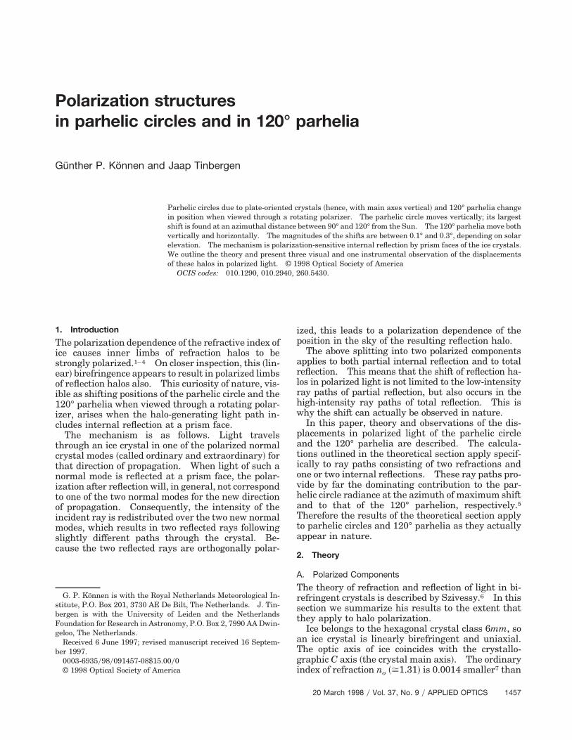
• The horizontal shift depends weakly on solar ele-vation and is visible to the eye for sharply defined120° parhelia.• The light of the limbs of a parhelic circle and a 120°parhelion should have a bluish coloring; the coloringwill be strongest where the limb polarization is larg-est. For sharply defined edges the coloring may bevisible to the naked eye.• No displacements or coloring occur for parhelic cir-cles generated by crystal orientations with the mainaxis horizontal. This applies to parhelic circles dueto column orientation and Parry orientation.
This research was supported by National ScienceFoundation grant DPP-8816515 and partly by theAntarctic Program of the Netherlands Organizationfor Scientific Research.
References and Notes1. G. P. Konnen, “Polarization of haloes and double refraction,”
Weather 32, 467–468 ~1977!.2. G. P. Konnen and J. Tinbergen, “Polarimetry of a 22° halo,”
Appl. Opt. 30, 3382–3400 ~1992!.
1464 APPLIED OPTICS y Vol. 37, No. 9 y 20 March 1998
3. G. P. Konnen, S. H. Muller, and J. Tinbergen, “Halo polariza-tion profiles and the interfacial angles of ice crystals,” Appl.Opt. 33, 4569–4579 ~1994!.
4. G. P. Konnen, “Identification of odd-radius halo arcs and of44°y46° parhelia by their inner-edge polarization,” Appl. Opt.37, 1450–1456 ~1998!.
5. W. Tape, Atmospheric Halos, Vol. 64 of Antarctic ResearchSeries ~American Geophysical Union, Washington, D.C., 1994!.
6. G. Szivessy, “Kristaloptik,” in Handbuch der Physik, H. Konen,ed. ~Springer, Berlin 1928!, Vol. 20, p. 702 and pp. 715–718.
7. H. E. Merwin, “Refractivity of birefringent crystals,” in Inter-national Critical Tables, E. W. Washburn, ed. ~McGraw-Hill,New York, 1930!, Vol. 7, pp. 16–33.
8. W. Snel van Royen ~Leiden, Netherlands 1580–1626!, lati-nized name Snellius, is often incorrectly retranslated as Snell.See also Ref. 9.
9. W. D. Bruton and G. W. Kattawar, “Unique temperature profilesfor the atmosphere below an observer from sunset images,”Appl. Opt. 36, 6957–6961 ~1997!; see authors’ note in Ref. 5.
10. E. Collett, Polarized Light: Fundamentals and Applications~Marcel Dekker, New York, 1993!.
11. P. Drude, “Rotationspolarisation,” in Handbuch der Physik, A.Winkelman, ed. ~Barth, Leipzig, 1906!, Vol. 4, pp. 1347 and1353.