Embed Size (px)
Citation preview

Polarization or phase insensitive fiber parametric amplifier with clamped output phase
Kyo Inoue* Division of Electrical, Electronic and Information Engineering, Osaka University, Osaka 565-0871, Japan
Abstract: This paper proposes a low polarization- or phase-dependent fiber parametric amplifier system with a clamped output phase, which consists of an orthogonally pumped nonlinear fiber and a fiber loop with a polarization beam splitter. Numerical calculations show that the proposed system exhibits a constant output phase, low insensitive to the signal input phase or polarization state.
©2015 Optical Society of America
OCIS codes: (190.4970) Parametric oscillators and amplifiers; (230.2285) Fiber devices and optical amplifiers.
References and links 1. Z. Tong, C. Lundström, P. A. Andrekson, M. Karlsson, and A. Bogris, “Ultralow noise, broadband phase-
sensitive optical amplifiers, and their applications,” IEEE J. Sel. Top. Quantum Electron. 18(2), 1016–1032 (2012).
2. K. Croussore and G. Li, “Phase and amplitude regeneration of differential phase-shift keyed signals using phase-sensitive amplification,” IEEE J. Sel. Top. Quantum Electron. 14(3), 648–658 (2008).
3. R. Slavík, A. Bogris, F. Paramigiani, J. Kakande, M. Westlund, M. Sköld, L. Grüner-Nielsen, R. Phelan, D. Syvridis, P. Petropulos, and D. J. Richardson, “Coherent all-optical phase and amplitude regenerator of binary phase-encoded signals,” IEEE J. Sel. Top. Quantum Electron. 18(2), 859–869 (2012).
4. Z. Zheng, L. An, X. Zhao, and X. Liu, “All-optical regeneration of DQPSK/QPSK signals based on phase-sensitive amplification,” Opt. Commun. 281(10), 2755–2759 (2008).
5. K. Inoue and S. Okazaki, “Phase-sensitive amplification in loop configuration for QPSK signal regeneration,” Opt. Commun. 298-299, 202–206 (2013).
6. A. Lorences-Riesgo, C. Lundström, F. Chiarello, M. Karisson, and P. A. Andrekson, “Phase-sensitive amplification and regeneration of dual-polarization BPSK without polarization diversity,” ECOC 2014, Tu.1.4.3 (2014).
7. F. Parmigiani, R. Slavík, G. Hesketh, and D. J. Richardson, “Quadrature decomposition of optical fields using two orthogonal phase sensitive amplifiers,” ECOC 2014, Tu.4.6.2 (2014).
8. A. Lorences-Riesgo, F. Chiarello, C. Lundström, M. Karlsson, and P. A. Andrekson, “Experimental analysis of degenerate vector phase-sensitive amplification,” Opt. Express 22(18), 21889–21902 (2014).
9. F. Parmigiani, G. D. Hesketh, R. Slavík, P. Horak, P. Petropoulos, and D. J. Richardson, “Optical phase quantizer based on phase sensitive four wave mixing at low nonlinear phase shift,” IEEE Photon. Technol. Lett. 26(21), 2146–2149 (2014).
10. K. Y. Wong, M. E. Marhic, K. Uesaka, and L. G. Kazovsky, “Polarization-independent two-pump fiber optical parametric amplifier,” IEEE Photon. Technol. Lett. 14(7), 911–913 (2002).
11. C. McKinstrie and S. Radic, “Phase-sensitive amplification in a fiber,” Opt. Express 12(20), 4973–4979 (2004). 12. K. Inoue, “Spectral inversion with no wavelength shift based on four-wave mixing with orthogonal pump
beams,” Opt. Lett. 22(23), 1772–1774 (1997). 13. K. Inoue, “Optical level equalization based on gain saturation in fiber optical parametric amplifier,” Electron.
Lett. 36(12), 1016 (2000).
1. Introduction
Phase-sensitive amplifiers (PSAs) based on a parametric interaction between pump and signal lights have unique properties such that only phase-synchronized signal is amplified and the output phase is clamped irrespective of the signal input phase [1]. These properties can be used to suppress phase noise in phase-modulated signals. Various studies have been reported on signal phase regeneration using PSAs [2–9]. However, polarization and phase synchronizations are issues for practical implementation. For obtaining a phase-clamped signal light, the polarization states of the pump and the signal lights should be aligned, and the mean signal light phase should be synchronized to the pump light phase.
#226627 - $15.00 USD Received 10 Nov 2014; revised 21 Jan 2015; accepted 21 Jan 2015; published 4 Feb 2015 © 2015 OSA 9 Feb 2015 | Vol. 23, No. 3 | DOI:10.1364/OE.23.003440 | OPTICS EXPRESS 3440
With this background, this paper proposes a parametric amplifier system that outputs a phase-clamped signal light, with low polarization or phase dependency. Two orthogonal pump lights are launched into a nonlinear fiber, following which the amplified signal light passes through a fiber loop with a polarization beam splitter (PBS). The operation of the proposed system is analyzed using nonlinear-coupled equations and is numerically calculated.
2. Configuration and operation
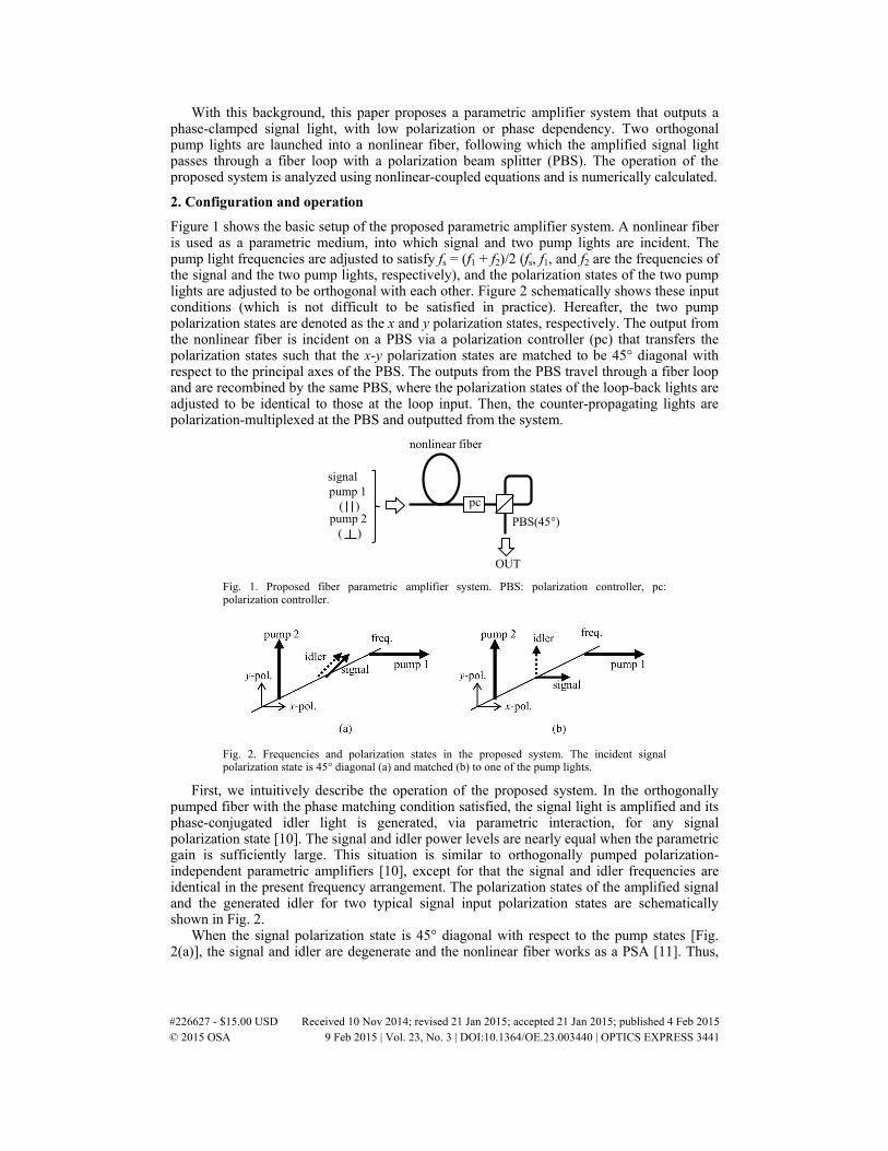
Figure 1 shows the basic setup of the proposed parametric amplifier system. A nonlinear fiber is used as a parametric medium, into which signal and two pump lights are incident. The pump light frequencies are adjusted to satisfy fs = (f1 + f2)/2 (fs, f1, and f2 are the frequencies of the signal and the two pump lights, respectively), and the polarization states of the two pump lights are adjusted to be orthogonal with each other. Figure 2 schematically shows these input conditions (which is not difficult to be satisfied in practice). Hereafter, the two pump polarization states are denoted as the x and y polarization states, respectively. The output from the nonlinear fiber is incident on a PBS via a polarization controller (pc) that transfers the polarization states such that the x-y polarization states are matched to be 45° diagonal with respect to the principal axes of the PBS. The outputs from the PBS travel through a fiber loop and are recombined by the same PBS, where the polarization states of the loop-back lights are adjusted to be identical to those at the loop input. Then, the counter-propagating lights are polarization-multiplexed at the PBS and outputted from the system.
nonlinear fiber
signal
pump 1
( )pump 2
( )PBS(45°)
OUT
pc
Fig. 1. Proposed fiber parametric amplifier system. PBS: polarization controller, pc: polarization controller.
Fig. 2. Frequencies and polarization states in the proposed system. The incident signal polarization state is 45° diagonal (a) and matched (b) to one of the pump lights.
First, we intuitively describe the operation of the proposed system. In the orthogonally pumped fiber with the phase matching condition satisfied, the signal light is amplified and its phase-conjugated idler light is generated, via parametric interaction, for any signal polarization state [10]. The signal and idler power levels are nearly equal when the parametric gain is sufficiently large. This situation is similar to orthogonally pumped polarization-independent parametric amplifiers [10], except for that the signal and idler frequencies are identical in the present frequency arrangement. The polarization states of the amplified signal and the generated idler for two typical signal input polarization states are schematically shown in Fig. 2.
When the signal polarization state is 45° diagonal with respect to the pump states [Fig. 2(a)], the signal and idler are degenerate and the nonlinear fiber works as a PSA [11]. Thus,
#226627 - $15.00 USD Received 10 Nov 2014; revised 21 Jan 2015; accepted 21 Jan 2015; published 4 Feb 2015 © 2015 OSA 9 Feb 2015 | Vol. 23, No. 3 | DOI:10.1364/OE.23.003440 | OPTICS EXPRESS 3441
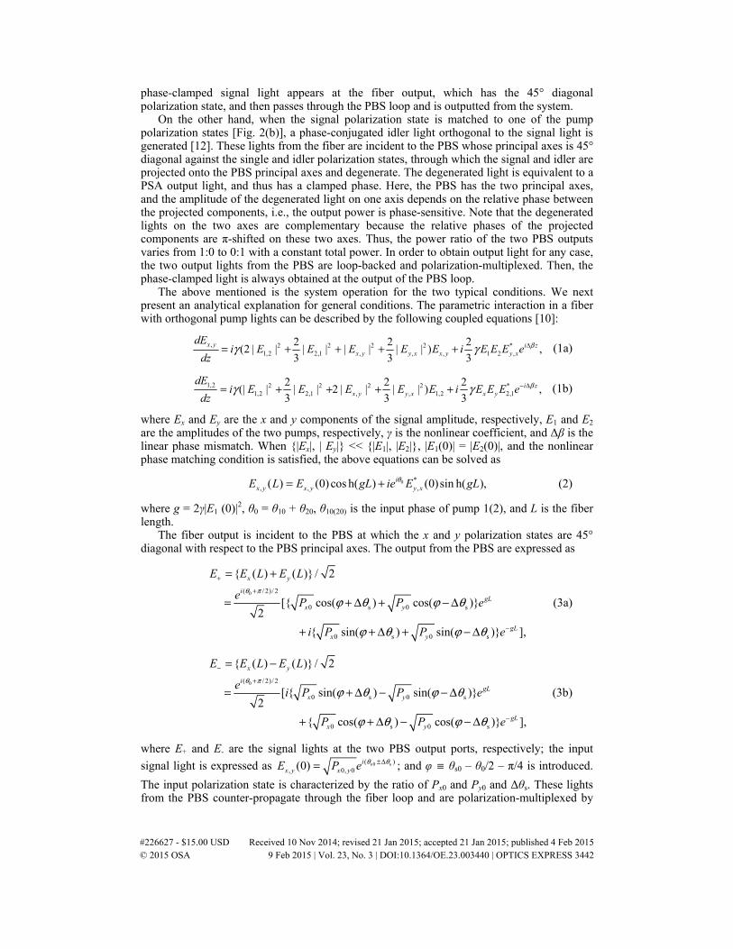
phase-clamped signal light appears at the fiber output, which has the 45° diagonal polarization state, and then passes through the PBS loop and is outputted from the system.
On the other hand, when the signal polarization state is matched to one of the pump polarization states [Fig. 2(b)], a phase-conjugated idler light orthogonal to the signal light is generated [12]. These lights from the fiber are incident to the PBS whose principal axes is 45° diagonal against the single and idler polarization states, through which the signal and idler are projected onto the PBS principal axes and degenerate. The degenerated light is equivalent to a PSA output light, and thus has a clamped phase. Here, the PBS has the two principal axes, and the amplitude of the degenerated light on one axis depends on the relative phase between the projected components, i.e., the output power is phase-sensitive. Note that the degenerated lights on the two axes are complementary because the relative phases of the projected components are π-shifted on these two axes. Thus, the power ratio of the two PBS outputs varies from 1:0 to 0:1 with a constant total power. In order to obtain output light for any case, the two output lights from the PBS are loop-backed and polarization-multiplexed. Then, the phase-clamped light is always obtained at the output of the PBS loop.
The above mentioned is the system operation for the two typical conditions. We next present an analytical explanation for general conditions. The parametric interaction in a fiber with orthogonal pump lights can be described by the following coupled equations [10]:
, 2 2 2 2 *1,2 2,1 , , , 1 2 ,
2 2 2(2 | | | | | | | | ) ,
3 3 3x y i z
x y y x x y y x
dEi E E E E E i E E E e
dzβγ γ Δ= + + + + (1a)
1,2 2 2 2 2 *1,2 2,1 , , 1,2 2,1
2 2 2(| | | | 2 | | | | ) ,
3 3 3i z
x y y x x y
dEi E E E E E i E E E e
dzβγ γ − Δ= + + + + (1b)
where Ex and Ey are the x and y components of the signal amplitude, respectively, E1 and E2 are the amplitudes of the two pumps, respectively, γ is the nonlinear coefficient, and Δβ is the linear phase mismatch. When {|Ex|, | Ey|} << {|E1|, |E2|}, |E1(0)| = |E2(0)|, and the nonlinear phase matching condition is satisfied, the above equations can be solved as
0 *, , ,( ) (0) cos h( ) (0)sin h( ),i
x y x y y xE L E gL ie E gLθ= + (2)
where g = 2γ|E1 (0)|2, θ0 = θ10 + θ20, θ10(20) is the input phase of pump 1(2), and L is the fiber length.
The fiber output is incident to the PBS at which the x and y polarization states are 45° diagonal with respect to the PBS principal axes. The output from the PBS are expressed as
0( / 2)/ 2
0 s 0 s
0 s 0 s
{ ( ) ( )} / 2
[{ cos( ) cos( )}2
{ sin( ) sin( )} ],
x y
igL
x y
gLx y
E E L E L
e P P e
i P P e
θ π
ϕ θ ϕ θ
ϕ θ ϕ θ
+
+
−
= +
= + Δ + − Δ
+ + Δ + − Δ
(3a)
0( / 2)/ 2
0 s 0 s
0 s 0 s
{ ( ) ( )} / 2
[ { sin( ) sin( )}2
{ cos( ) cos( )} ],
x y
igL
x y
gLx y
E E L E L
e i P P e
P P e
θ π
ϕ θ ϕ θ
ϕ θ ϕ θ
−
+
−
= −
= + Δ − − Δ
+ + Δ − − Δ
(3b)
where E+ and E- are the signal lights at the two PBS output ports, respectively; the input
signal light is expressed as s 0 s( ), 0, 0(0) i
x y x yE P e θ θ±Δ= ; and φ ≡ θs0 – θ0/2 – π/4 is introduced.
The input polarization state is characterized by the ratio of Px0 and Py0 and Δθs. These lights from the PBS counter-propagate through the fiber loop and are polarization-multiplexed by
#226627 - $15.00 USD Received 10 Nov 2014; revised 21 Jan 2015; accepted 21 Jan 2015; published 4 Feb 2015 © 2015 OSA 9 Feb 2015 | Vol. 23, No. 3 | DOI:10.1364/OE.23.003440 | OPTICS EXPRESS 3442

the same PBS. The output from the PBS loop is expressed as Eout = (E+, E-)T, which is the
output from our system. The signal output power is expressed as
2 2out 0 0 0 0| | | | ( ) cos h(2 ) 2 cos( )sin h(2 ).x y x yP E E P P gL P P gLϕ+ −= + = + + (4)
Provided that the pump and signal phases satisfy φ = 0, i.e., the phase synchronization is made, Eq. (4) is written as
2 2out 0 0 0 0( ) / 2 ( ) / 2.gL gL
x y x yP P P e P P e−= + + − (5)
This equation shows that the signal output is always obtained irrespective of the polarization state of the input signal. When the parametric gain is sufficiently large as egL >> 1, Eq. (5) is rewritten as
2 2out 0 0( ) / 2.gL
x yP P P e= + (6)
This equation sows that the output power is at between P0e2gL and P0e2gL /2 with P0 being the total signal input power, depending on the input polarization state. This property of the output power is identical to a conventional orthogonally-pumped degenerate parametric amplifier with no PBS loop [9].
The uniqueness of the present system different from the conventional orthogonally-pumped amplifier [9] is the output phase property. For a large parametric gain, Eq. (3) is rewritten as
0( / 2 / 4)0 s 0 s{ cos( ) cos( )} / 2,gL i
x yE e P Pθ π ϕ θ ϕ θ+ ++ = + Δ + − Δ (7a)
0( / 2 3 /4)0 s 0 s{ sin( ) sin( )} / 2.gL i
x yE e P Pθ π ϕ θ ϕ θ+ +− = + Δ − − Δ (7b)
These equations show that the phases of each output component E+ and E- are constant irrespective of the signal input phase and polarization state. Thus, the phase clamping effect with low polarization dependency is obtained in the present system. On the other hand, the output phase of the conventional orthogonally-pumped amplifier is dependent on the signal input phase, as indicated in Eq. (2), and no phase clamping effect is accompanied.
The present system also has the property of low dependency on the input phase, provided that the signal input polarization state is almost matched to either one of the pump light waves, Under this polarization condition, { 0 0xP P≈ , 0 0yP ≈ } or { 0 0xP ≈ , 0 0yP P≈ }, and thus
out 0 cos h(2 )P P gL≈ in Eq. (5), which indicates that the signal output power is almost independent on the input phase. The light amplitude under this condition is obtained from Eq. (3) as
0( /2 /4)
0 [cos( / 4) sin( / 4) ],2
igL gLeE P e i e
θ π
ϕ π ϕ π+
−+ ≈ + + + (8a)
0( / 2 / 4)
0 [ sin( / 4) cos( / 4) ].2
igL gLeE P i e e
θ π
ϕ π ϕ π+
−− ≈ + + + (8b)
For a high parametric gain,
0( / 2 / 4)
0 cos( / 4) ,2
igLeE P e
θ π
ϕ π+
+ ≈ + (9a)
#226627 - $15.00 USD Received 10 Nov 2014; revised 21 Jan 2015; accepted 21 Jan 2015; published 4 Feb 2015 © 2015 OSA 9 Feb 2015 | Vol. 23, No. 3 | DOI:10.1364/OE.23.003440 | OPTICS EXPRESS 3443

0( /2 3 / 4)
0 sin( / 4)2
igLeE P e
θ π
ϕ π+
− ≈ + (9b)
These equations show that the property of the constant output phase is still obtained in a high-gain amplifier system, while the output power is insensitive to the input phase. When egL >> 1 is not satisfied, however, E+, - simultaneously includes the in-phase and the quadrature phase components whose ratio is dependent on the input phase, meaning that the output phase depends on the input phase.
In the last of this section, we mention previous works similar to the present one. References [6–9] study orthogonally-pumped parametric amplification systems with the signal and idler frequencies degenerated. However, a PBS is not equipped after the amplifying fiber in Refs [6–8], and the phase-clamping effect is obtainable only when the input signal polarization state is 45° diagonal with respect to the pump polarization states. One work presents an orthogonally-pumped amplifier followed by a polarizer [9], where the signal phase is clamped at the polarizer output. However, the signal input phase and polarization state should be adjusted to obtain the signal output.
3. Calculations
In this section, we present numerical calculations using Eq. (1) for quantitatively examining the characteristics of the proposed parametric amplifier system.
3.1 Output phase
The main concern in this paper is the phase of the output signal light. Our system has two output components, i.e., E+ and E-, and their power ratio |E+|2:|E-|
2 varies between 1:0 and 0:1, depending on the signal input conditions. In such a situation, it may be questionable how to define the output phase. In this subsection, we discuss the output phase of our system, before presenting calculation results.
When considering the phase-clamping effect in a PSA, we usually are interested in the phase of the output signal around gain peak conditions. Similarly, we concern the output phase for the input phase around a value maximizing the signal gain in the present system. In order to evaluate such an output phase, we translate the polarization coordinate so that the output light at a gain peak condition turns to have just one polarization component, and we regard the phase of this component in the translated coordinate as the output phase of the system. To be specific, an output state (E+, E-)
T is transformed as
(0)* (0)*
(0) (0)(0) 2 (0) 2
1
| | | |
p
q
E EE EE EE EE E
++ −
−− ++ −
= −+
(10)
where (E+(0), E-
(0))T is the output state at a gain peak condition. With this transformation, the
state transformed from (E+(0), E-
(0))T becomes ( (0) 2 (0) 2| | | |E E+ −+ , 0)T; that is, the translated
light has only Ep component. Then, the phase of Ep is regarded as the output phase of our system, which is calculated in the following.
3.2 Unsaturated condition
First, the unsaturated conditions are evaluated. The results are shown in Fig. 3, where the signal gain and the output phase as a function of the signal input phase are plotted for various input polarization states. The signal gain is maximum at input phases of 0.5π± , and the output phase is constant around the gain maximum conditions and jumps at the middle between the gain peaks. This output phase property is identical to that of conventional PSAs. Further, Fig. 3 shows a unique property of the proposed system in that signal gain is obtained for any polarization state at the gain peak conditions, i.e., low polarization dependency
#226627 - $15.00 USD Received 10 Nov 2014; revised 21 Jan 2015; accepted 21 Jan 2015; published 4 Feb 2015 © 2015 OSA 9 Feb 2015 | Vol. 23, No. 3 | DOI:10.1364/OE.23.003440 | OPTICS EXPRESS 3444

compared with conventional PSAs. The variation in the peak gain is within 3 dB; this result is consistent with the result of the analysis presented in the previous section
(a) Px0:Py0 = 1:1, Δφ = π
ou
tpu
t ph
ase (rad/ π
)
sign
al g
ain
(d
B)
20
15
10
5
0-1 -0.5 0 0.5 1
input phase (rad/π)
4.0
3.5
3.0
2.5
2.0
1.5
(b) Px0:Py0 = 1:1, Δφ = 04.0
3.5
3.0
2.5
2.0
1.5ou
tpu
t ph
ase (rad/π
)
20
15
10
5
0
sign
al g
ain
(d
B)
-1 -0.5 0 0.5 1input phase (rad/π)
(c) Px0:Py0 = 1:9, Δφ = π
ou
tpu
t ph
ase (rad/π
)sign
al g
ain
(d
B)
20
15
10
5
0-1 -0.5 0 0.5 1
input phase (rad/π)
4.0
3.5
3.0
2.5
2.0
1.5
(d) Px0:Py0 = 1:9, Δφ = 03.5
3.0
2.5
2.0
1.5
1.0
ou
tpu
t ph
ase (rad/ π
)
20
15
10
5
0
sign
al g
ain
(d
B)
-1 -0.5 0 0.5 1input phase (rad/π)
(e) Px0:Py0 = 1:99, Δφ = πou
tpu
t ph
ase (rad/π
)sign
al g
ain
(d
B)
20
15
10
5
0-1 -0.5 0 0.5 1
input phase (rad/π)
3.0
2.5
2.0
1.5
1.0
0.5
(f) Px0:Py0 = 1:99, Δφ = 03.5
3.0
2.5
2.0
1.5
1.0
ou
tpu
t ph
ase (rad/π
)
20
15
10
5
0
sign
al g
ain
(d
B)
-1 -0.5 0 0.5 1input phase (rad/π)
-1 -0.5 0 0.5 1input phase (rad/π)
sign
al g
ain
(d
B)
20
15
10
5
0
3.5
3.0
2.5
2.0
1.5
ou
tpu
t ph
ase (rad/π
)
(g) Px0:Py0 = 0:1
Fig. 3. Amplificatiion characteristics under unsaturated conditions. Solid line: signal gain, broken line: output phase. The assumed parameters are γ = 12 /(W-km), fiber length = 400 m, pump input power = 0.6 W/ch, pump input phase θ0 = 0.5π, and signal input power = −10 dBm. Nonlinear phase matching is assumed to be satisfied.
The figures also show that the gain dependence on the input phase becomes low as the input polarization state approaches to one of the pump polarization states, and is completely flat when the polarization state is perfectly matched [Fig. 3(g)]. The difference between the maximum and minimum gains is consistent with the result of the analysis presented in the previous section. This is another unique property of the proposed parametric amplifier system, i.e., low phase dependency.
#226627 - $15.00 USD Received 10 Nov 2014; revised 21 Jan 2015; accepted 21 Jan 2015; published 4 Feb 2015 © 2015 OSA 9 Feb 2015 | Vol. 23, No. 3 | DOI:10.1364/OE.23.003440 | OPTICS EXPRESS 3445

3.3 Gain-saturated condition
When a high-power signal is incident to an amplifier, the signal gain is saturated and the signal output power is clamped. Under such gain-saturated conditions, the gain variation observed in Fig. 3 is expected to be reduced. In order to confirm the gain saturation effect, the amplification characteristics for a large signal input were calculated.
First, the signal gain was calculated as a function of the input power for different polarization states at the gain peak condition, i.e., at an input phase of 0.5π. The results are shown in Fig. 4. The gain difference at a small input power decreases with an increase in the input power, and the signal gain for different polarization states becomes identical at a large input level of 16 dBm. This result suggests that the polarization dependence of the signal gain is completely suppressed.
-5 0 5 10 15 20
input power (dBm)
Px0:Py0 = 1:1
sign
al g
ain
(d
B)
20
15
10
5
1:9
1:99
Fig. 4. Signal gain as a function of signal input power. The input phase is 0.5π givng the maximum gain. The other conditions are the same as those in Fig. 3.
Next, the signal gain and the output phase were calculated as a function of the input phase under a gain-saturated condition. The results are shown in Fig. 5, where the input power is 16 dBm. The gain variation shown in these figures is less than that shown in Fig. 3 while preserving the phase-clamping properties.
ou
tpu
t ph
ase (rad/π
)
sign
al g
ain
(d
B)
15
10
5
0-1 -0.5 0 0.5 1
input phase (rad/π)
4.0
3.5
3.0
2.5
2.0
1.5-1 -0.5 0 0.5 1
input phase (rad/π)
15
10
5
0
sign
al g
ain
(d
B)
4.0
3.5
3.0
2.5
2.0
1.5
ou
tpu
t ph
ase (rad/π
)
-1 -0.5 0 0.5 1input phase (rad/π)
sign
al g
ain
(d
B)
15
10
5
0
ou
tpu
t ph
ase (rad/π
)
4.0
3.5
3.0
2.5
2.0
1.5
(a) Px0:Py0 = 1:1, Δφs = π/2 (b) Px0:Py0 = 1:9, Δφs = π/2 (c) Px0:Py0 = 1:99, Δφs = π/2
Fig. 5. Amplification characteristics under gain-saturated condition. The input phase is 0.5π givng the maximum gain in (a). Solid and broken lines denote the gain and the output phase, respectively, and the signal input power is 16 dBm. The other conditions are the same as those in Fig. 3.
In the above calculations, the output phase is defined based on the output state at a gain peak condition. However, when the input phase dependency is low, as shown in Fig. 5(c), amplification properties around an input phase other than that condition may be interest as well. Calculations employing another definition of the output phase were carried out in order to observe the amplification characteristics for such cases. The results of these calculations are shown in Fig. 6, where the output states at input phases of −0.4π and 0.1π are chosen for defining the output phase in (a) and (b), respectively. The center of the clamped phase region is positioned at the chosen input phase. This result suggests that the proposed system is applicable to BPSK signals even when the system operates insensitive to the input phase.
#226627 - $15.00 USD Received 10 Nov 2014; revised 21 Jan 2015; accepted 21 Jan 2015; published 4 Feb 2015 © 2015 OSA 9 Feb 2015 | Vol. 23, No. 3 | DOI:10.1364/OE.23.003440 | OPTICS EXPRESS 3446

-1 -0.5 0 0.5 1sig. input phase (rad/π)
sign
al g
ain
(d
B)
ou
tpu
t ph
ase (rad/π
)
3.0
2.5
2.0
1.5
1.0
0.5-1 -0.5 0 0.5 1sig. input phase (rad/π)
ou
tpu
t ph
ase (rad/ π
)
3.5
3.0
2.5
2.0
1.5
1.0
15
10
5
0
sign
al g
ain
(d
B)
15
10
5
0
(a) For θs0 = -0.4π (b) For θs0 = 0.1π
Fig. 6. Amplification characteristics under gain-saturated condition. Solid line: signal gain, broken line: output phase. The other conditions are the same as those in Fig. 5(c).
3.4 Optical limiting property
The gain saturation in parametric amplifiers can be utilized to suppress amplitude fluctuations [2,3,13]. In order to confirm whether the present system operates as such an optical limiter, the output power as a function of the input power was calculated. The results are shown in Fig. 7. A limiting property is observed for any polarization state [Fig. 7(a)] or any input phase [Fig. 7(b)].
ou
tpu
t p
ow
er (
W)
0.6
0.4
0.2
00 2 4 6 8 10
input power (10-2W)
0 2 4 6 8 10input power (10-2W)
ou
tpu
t p
ow
er (
W)
0.6
0.4
0.2
0
Px0 : Py01 : 1
1 : 9
1 : 99
θ s0 = 0.5π
θ s0 = 0
θ s0 = 0.5π Px0:Py0 = 1:99
(a) Phase-synchronized condition. (b) Polarization-aligned condition.
Fig. 7. Output power as a function of input power. (a) The input phase is fixed at a gain peak condition of 0.5π and the polarization state is assumed to be different. (b) The polarization state is aligned as Px0:Py0 = 1:99 and the input phase is at a gain maximum condition (θs0 = 0.5π) or a gain minimum condition (θs0 = 0).
4. Summary
A polarization or phase insensitive parametric amplifier system with a clamped output phase was proposed, which consists of a nonlinear fiber with orthogonal pump lights and a fiber loop with a polarization beam splitter. An analysis and numerical calculations based on nonlinear coupled equations demonstrate that the proposed system exhibits a constant output phase insensitive to the signal input phase or polarization state.
#226627 - $15.00 USD Received 10 Nov 2014; revised 21 Jan 2015; accepted 21 Jan 2015; published 4 Feb 2015 © 2015 OSA 9 Feb 2015 | Vol. 23, No. 3 | DOI:10.1364/OE.23.003440 | OPTICS EXPRESS 3447