Embed Size (px)
Citation preview
Polarization of Light
Introduction
Light, viewed classically, is a transverse electromagnetic wave. Namely, the underlying os-
cillation (in this case oscillating electric and magnetic fields) is along directions perpendicular
to the direction of propagation. This is in contrast to longitudinal waves, such as sound waves,
in which the oscillation is confined to the direction of propagation. Light is said to be linearly
polarized if its oscillation is confined to one direction (the direction of the oscillation of the
electric field is defined as the direction of polarization). Most light sources in nature emit unpo-
larized light i.e., light consists of many wave trains whose directions of oscillation are completely
random.
Light may be polarized by passing it through a sheet of commercial material called Polaroid,
invented by E.H. Land in 1938. A sheet of Polaroid transmits only the component of light
polarized along a particular direction and absorbs the component perpendicular to that direction.
Consider a light beam in the z direction incident on a Polaroid which has its transmission
axis in the y direction. On the average, half of the incident light has its polarization axis in the y
direction and half in the x direction. Thus half the intensity is transmitted, and the transmitted
light is linearly polarized in the y direction.
Malus’ law
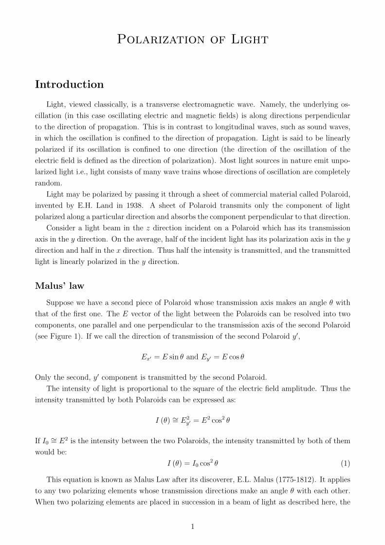
Suppose we have a second piece of Polaroid whose transmission axis makes an angle θ with
that of the first one. The E vector of the light between the Polaroids can be resolved into two
components, one parallel and one perpendicular to the transmission axis of the second Polaroid
(see Figure 1). If we call the direction of transmission of the second Polaroid y′,
Ex′ = E sin θ and Ey′ = E cos θ
Only the second, y′ component is transmitted by the second Polaroid.
The intensity of light is proportional to the square of the electric field amplitude. Thus the
intensity transmitted by both Polaroids can be expressed as:
I (θ) ∼= E2y′ = E2 cos2 θ
If I0 ∼= E2 is the intensity between the two Polaroids, the intensity transmitted by both of them
would be:
I (θ) = I0 cos2 θ (1)
This equation is known as Malus Law after its discoverer, E.L. Malus (1775-1812). It applies
to any two polarizing elements whose transmission directions make an angle θ with each other.
When two polarizing elements are placed in succession in a beam of light as described here, the
1
first is called polarizer and the second is called analyzer. As you will see, no light reaches the
photocell when the polarizer and analyzer are crossed (θ = 90◦).
ht
Figure 1: Two Polaroids whose transmission directions make an angle θ with each other.
Theory for three polarizers
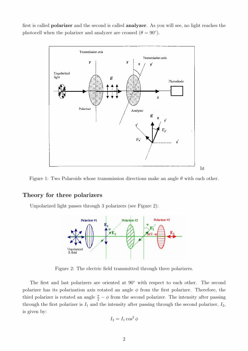
Unpolarized light passes through 3 polarizers (see Figure 2):
Figure 2: The electric field transmitted through three polarizers.
The first and last polarizers are oriented at 90◦ with respect to each other. The second
polarizer has its polarization axis rotated an angle φ from the first polarizer. Therefore, the
third polarizer is rotated an angle π2− φ from the second polarizer. The intensity after passing
through the first polarizer is I1 and the intensity after passing through the second polarizer, I2,
is given by:
I2 = I1 cos2 φ
2
The intensity after the third polarizer, I3, is given by:
I3 = I2 cos2(π
2− φ
)= I1 cos2 φ cos2
(π2− φ
)(2)
Rearranging Equation 2, we obtain:
I3 =I14
sin2(2φ) (3)
Because the data acquisition begins when the transmitted intensity through Polarizer 3 is a
maximum, the angle Θ measured in the experiment is zero when the second polarizer is 45◦
from the angle φ. Thus the angle φ is related to the measured angle Θ by:
φ = 45◦ + Θ (4)
Reflectance/Brewster’s Angle
Consider unpolarized light incident on a surface separating air and glass or air and water.
Define the plane of incidence, containing the incident, reflected and refracted rays as well as the
normal to the surface.
When light is reflected from a flat surface, the reflected light is partially polarized. This
is due to the fact that the reflectance of light R = (Reflected Intensity)/(Incident Intensity)
depends on the polarization itself. The degree of polarization depends on the angle of incidence
and the indices of refraction of the two media.
For reflection at an air-glass interface (indices of refraction n1 for air and n2 for glass), Fresnel
equations give the reflection coefficients r‖, r⊥:
r⊥ =n1 cos θ1 − n2 cos θ2n1 cos θ1 + n2 cos θ2
(5a)
r‖ =n1 cos θ2 − n2 cos θ1n1 cos θ2 + n2 cos θ1
(5b)
where θ1 is the angle of incidence, and θ2 is the angle of refraction.
Above r‖ and r⊥ refer to the reflection coefficients for polarized light whose direction of
polarization lie in the plane of incidence and perpendicular to the plane of incidence, respectively.
Reflectance R (parallel or perpendicular) is defined as the square of the corresponding re-
flection coefficient: R‖ = r2‖, R⊥ = r2⊥Note that θ2 is not measured in this experiment and must be inferred from Snells law of
refraction:sin θ2sin θ1
=n1
n2
(6)
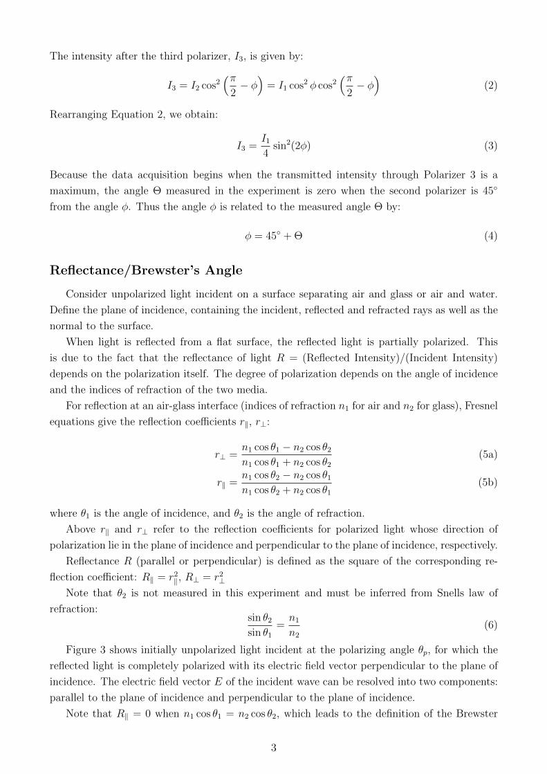
Figure 3 shows initially unpolarized light incident at the polarizing angle θp, for which the
reflected light is completely polarized with its electric field vector perpendicular to the plane of
incidence. The electric field vector E of the incident wave can be resolved into two components:
parallel to the plane of incidence and perpendicular to the plane of incidence.
Note that R‖ = 0 when n1 cos θ1 = n2 cos θ2, which leads to the definition of the Brewster
3
angle (or polarizing angle):
tan θp =n2
n1
(7)
Here θp is the angle of incidence of unpolarized light which makes the reflected light completely
polarized in the perpendicular direction to the plane of incidence (Sir David Brewster, 1812).
When the angle of incidence of the initially unpolarized light is θp, the reflected and refracted
rays are perpendicular to each other.
Figure 3: Unpolarized light incident at the polarizing angle.
Note: If the incident light has no component of E perpendicular to the plane of incidence,
there is no reflected light.
Apparatus, Experiment and Procedure
Malus’ Law: Apparatus Notes
Be careful not to leave your fingerprints on optical surfaces.
- Rotate the aperture disk so the translucent mask covers the opening to the light sensor.
- Verify that the Rotary motion sensor is mounted on the polarizer bracket and connected to
the polarizer pulley with the plastic belt.
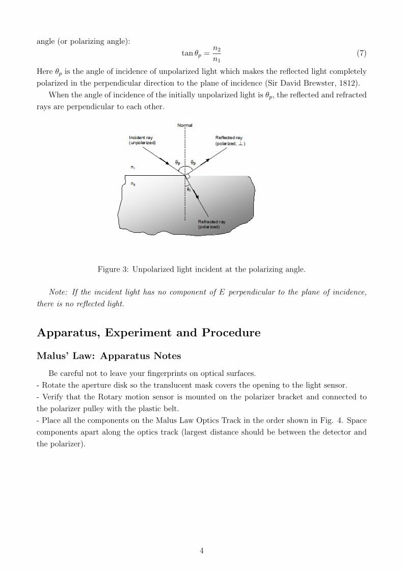
- Place all the components on the Malus Law Optics Track in the order shown in Fig. 4. Space
components apart along the optics track (largest distance should be between the detector and
the polarizer).
4
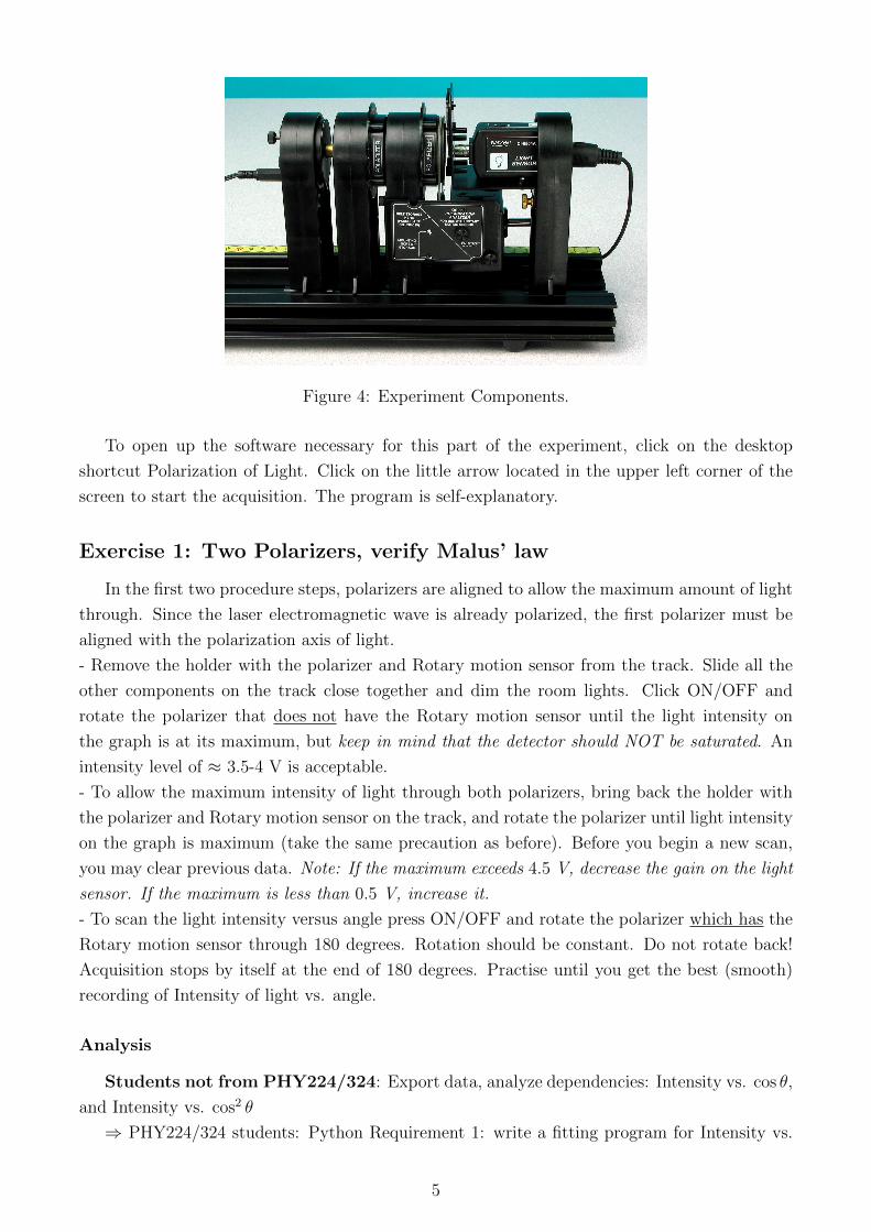
Figure 4: Experiment Components.
To open up the software necessary for this part of the experiment, click on the desktop
shortcut Polarization of Light. Click on the little arrow located in the upper left corner of the
screen to start the acquisition. The program is self-explanatory.
Exercise 1: Two Polarizers, verify Malus’ law
In the first two procedure steps, polarizers are aligned to allow the maximum amount of light
through. Since the laser electromagnetic wave is already polarized, the first polarizer must be
aligned with the polarization axis of light.
- Remove the holder with the polarizer and Rotary motion sensor from the track. Slide all the
other components on the track close together and dim the room lights. Click ON/OFF and
rotate the polarizer that does not have the Rotary motion sensor until the light intensity on
the graph is at its maximum, but keep in mind that the detector should NOT be saturated. An
intensity level of ≈ 3.5-4 V is acceptable.
- To allow the maximum intensity of light through both polarizers, bring back the holder with
the polarizer and Rotary motion sensor on the track, and rotate the polarizer until light intensity
on the graph is maximum (take the same precaution as before). Before you begin a new scan,
you may clear previous data. Note: If the maximum exceeds 4.5 V, decrease the gain on the light
sensor. If the maximum is less than 0.5 V, increase it.
- To scan the light intensity versus angle press ON/OFF and rotate the polarizer which has the
Rotary motion sensor through 180 degrees. Rotation should be constant. Do not rotate back!
Acquisition stops by itself at the end of 180 degrees. Practise until you get the best (smooth)
recording of Intensity of light vs. angle.
Analysis
Students not from PHY224/324: Export data, analyze dependencies: Intensity vs. cos θ,
and Intensity vs. cos2 θ
⇒ PHY224/324 students: Python Requirement 1: write a fitting program for Intensity vs.
5
cos2 θ. You have to include experimental errors for both light intensity and angle readings. The
data set includes about 300 values (Intensity, θ). Compare with Malus Law prediction, Eq. 1.
Exercise 2: Three Polarizers
Repeat the experiment with 3 polarizers (see setup in Figure 5). Remove the rotary motion
sensor from the track, insert Polarizer 1 and rotate it until the transmitted light is a maximum.
Insert Polarizer 2 and rotate it until the transmitted light is a minimum.
Place the rotary motion sensor between the two polarizers and collect data through 360o. Try
the qualitative fitter from the LabView application.
Figure 5: Experiment components for the three polarizer part of the experiment.
Select your data from 2 polarizers and from 3 polarizers. What two things are different for
the Intensity vs. Angle graph for 3 polarizers compared to 2 polarizers?
Export data and find the best fit matching Equation (3). Include experimental errors.
⇒ Python Requirement 2 (PHY224/324 students only): write a fitting program using your
data and the intensity function from Equation 3.
Questions
- For 3 polarizers, what is the angle between the middle polarizer and the first polarizer to get
the maximum transmission through all 3 polarizers? Remember: in the experiment, the angle
of the middle polarizer automatically reads zero when you start taking data but that doesn’t
mean the middle polarizer is aligned with the first polarizer
- For 3 polarizers, what is the angle between the middle polarizer and the first polarizer to get
the minimum transmission through all 3 polarizers?
Brewster’s Angle: Apparatus Notes
Light from a diode laser is reflected off the flat side of an acrylic semi-circular lens. The
reflected light passes through a square polarizer and is detected by a light sensor. The angle of
reflection is measured by a rotary motion sensor mounted on the spectrophotometer table. The
intensity of the reflected polarized light versus reflected angle is graphed to determine the angle
6
at which the light intensity is a minimum. This is Brewster’s Angle, which is used to calculate
the index of refraction of acrylic (Eq. 7).
You will use this apparatus to measure the intensity of parallel and perpendicular polarization
components of refrected light at a range of incident angles. The preliminary setup include:
- Move the diode laser to the optics bench marked Brewsters angle,
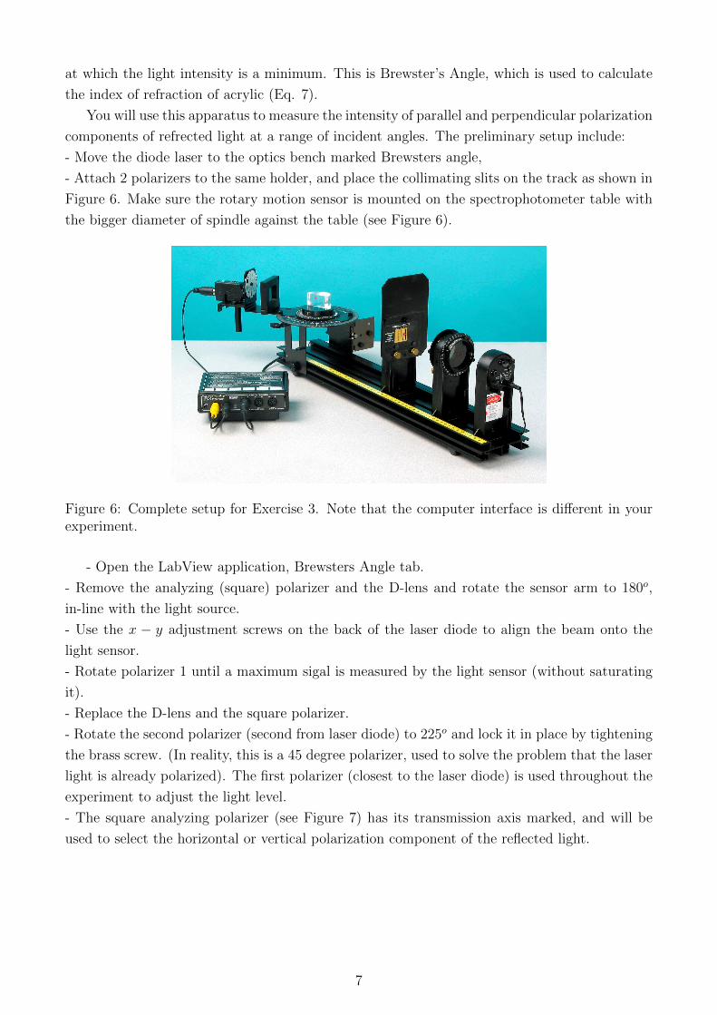
- Attach 2 polarizers to the same holder, and place the collimating slits on the track as shown in
Figure 6. Make sure the rotary motion sensor is mounted on the spectrophotometer table with
the bigger diameter of spindle against the table (see Figure 6).
Figure 6: Complete setup for Exercise 3. Note that the computer interface is different in yourexperiment.
- Open the LabView application, Brewsters Angle tab.
- Remove the analyzing (square) polarizer and the D-lens and rotate the sensor arm to 180o,
in-line with the light source.
- Use the x − y adjustment screws on the back of the laser diode to align the beam onto the
light sensor.
- Rotate polarizer 1 until a maximum sigal is measured by the light sensor (without saturating
it).
- Replace the D-lens and the square polarizer.
- Rotate the second polarizer (second from laser diode) to 225o and lock it in place by tightening
the brass screw. (In reality, this is a 45 degree polarizer, used to solve the problem that the laser
light is already polarized). The first polarizer (closest to the laser diode) is used throughout the
experiment to adjust the light level.
- The square analyzing polarizer (see Figure 7) has its transmission axis marked, and will be
used to select the horizontal or vertical polarization component of the reflected light.
7
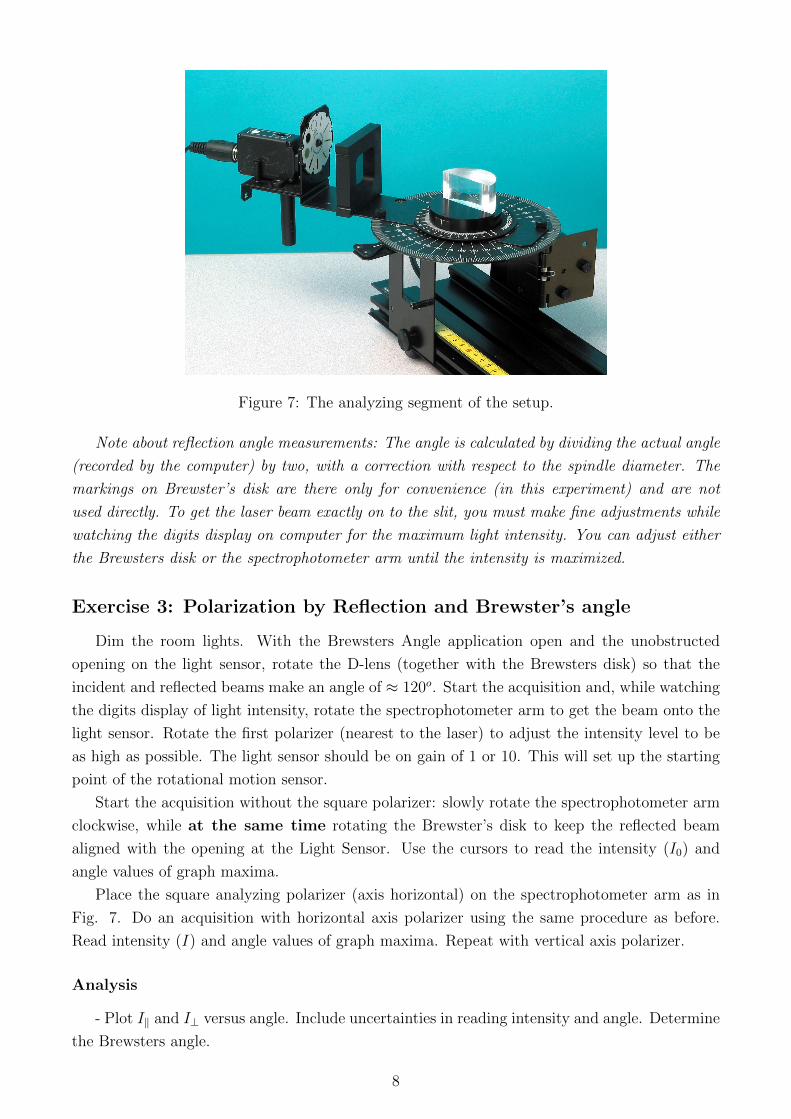
Figure 7: The analyzing segment of the setup.
Note about reflection angle measurements: The angle is calculated by dividing the actual angle
(recorded by the computer) by two, with a correction with respect to the spindle diameter. The
markings on Brewster’s disk are there only for convenience (in this experiment) and are not
used directly. To get the laser beam exactly on to the slit, you must make fine adjustments while
watching the digits display on computer for the maximum light intensity. You can adjust either
the Brewsters disk or the spectrophotometer arm until the intensity is maximized.
Exercise 3: Polarization by Reflection and Brewster’s angle
Dim the room lights. With the Brewsters Angle application open and the unobstructed
opening on the light sensor, rotate the D-lens (together with the Brewsters disk) so that the
incident and reflected beams make an angle of ≈ 120o. Start the acquisition and, while watching
the digits display of light intensity, rotate the spectrophotometer arm to get the beam onto the
light sensor. Rotate the first polarizer (nearest to the laser) to adjust the intensity level to be
as high as possible. The light sensor should be on gain of 1 or 10. This will set up the starting
point of the rotational motion sensor.
Start the acquisition without the square polarizer: slowly rotate the spectrophotometer arm
clockwise, while at the same time rotating the Brewster’s disk to keep the reflected beam
aligned with the opening at the Light Sensor. Use the cursors to read the intensity (I0) and
angle values of graph maxima.
Place the square analyzing polarizer (axis horizontal) on the spectrophotometer arm as in
Fig. 7. Do an acquisition with horizontal axis polarizer using the same procedure as before.
Read intensity (I) and angle values of graph maxima. Repeat with vertical axis polarizer.
Analysis
- Plot I‖ and I⊥ versus angle. Include uncertainties in reading intensity and angle. Determine
the Brewsters angle.
8
- Use Brewster’s angle to calculate the index of refraction of acrylic using Equation 7. Use
n1 = 1.
- Calculate the parallel and perpendicular reflectances using Fresnel equations (5a and 5b).
⇒ Python Requirement 3 (PHY224/324 students only): do the three analysis steps above by
writing a program to fit the data and to output Brewsters angle, index of refraction of acrylic
and the two reflectances from (5a) and (5b).
Questions
1. Would Brewster’s angle be more or less for light in air reflecting off water?
2. How would data look like for an arrangement with vertical square polarizer?
3. How do polarized sunglasses reduce glare? Which direction is the axis of polarization in a
pair of polarized sunglasses? How could you check this?
References
1. Halliday/Resnick/Walker Fundamentals of Physics, Chapter 33, 7th ed. Wiley 2005
2. PASCO EX9917A and EX9919 guide sheets (written by Ann Hanks)
Revised by Ruxandra Serbanescu in 2017 with notes from Kyle Manchee. The acquisition
DAQ board was built and programmed by Larry Avramidis.
9