Embed Size (px)
Citation preview
POLARIMETRY
SHUBHENDU JOARDARB.Tech. (Electronics, NIT Calicut)M.S. (Microwaves, IIT Madras)
F.I.E.T.E. (IETE, India)Ph.D. (Physics, University of Kalyani)

License
This presentation is copyrighted to the author. All are free to use and distribute this presentation for non-commertial purposes like teaching, learning, science and education provided the contents are not modified. Figures and equations or any part of it may be copied for any similar usage provided the author is acknowledged. One should not aim to use this for destructive, non-scientific or non-educational purposes. – AUTHOR –
Introduction
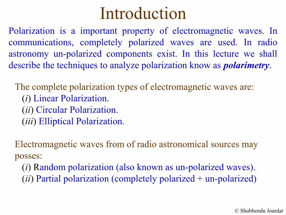
The complete polarization types of electromagnetic waves are: (i) Linear Polarization. (ii) Circular Polarization. (iii) Elliptical Polarization.
Electromagnetic waves from of radio astronomical sources may posses: (i) Random polarization (also known as un-polarized waves). (ii) Partial polarization (completely polarized + un-polarized)
© Shubhendu Joardar
Polarization is a important property of electromagnetic waves. In communications, completely polarized waves are used. In radio astronomy un-polarized components exist. In this lecture we shall describe the techniques to analyze polarization know as polarimetry.
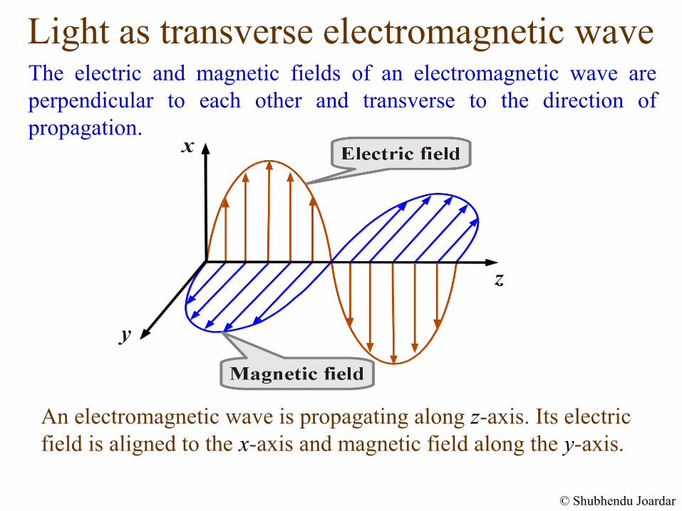
Light as transverse electromagnetic waveThe electric and magnetic fields of an electromagnetic wave are perpendicular to each other and transverse to the direction of propagation.
An electromagnetic wave is propagating along z-axis. Its electric field is aligned to the x-axis and magnetic field along the y-axis.
© Shubhendu Joardar
Linear Polarization
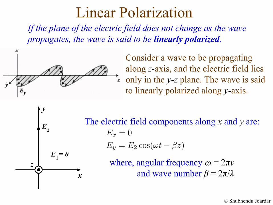
where, angular frequency ω = 2πν and wave number β = 2π/λ
If the plane of the electric field does not change as the wave propagates, the wave is said to be linearly polarized.
The electric field components along x and y are:
© Shubhendu Joardar
Consider a wave to be propagating along z-axis, and the electric field lies only in the y-z plane. The wave is said to linearly polarized along y-axis.
Components of a Linearly Polarized Wave
© Shubhendu Joardar
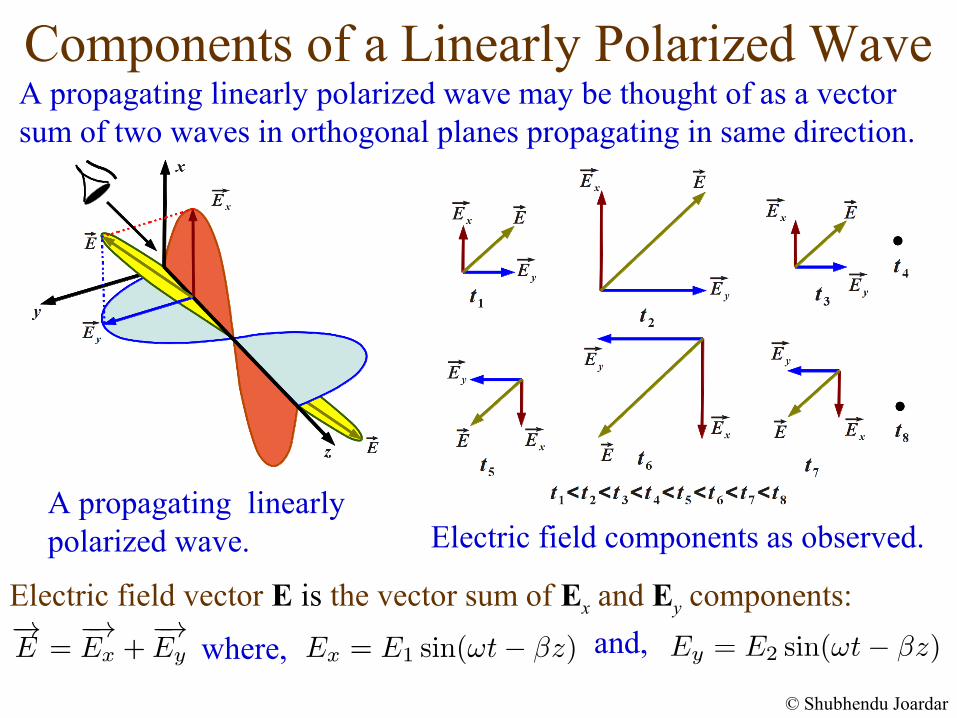
A propagating linearly polarized wave may be thought of as a vector sum of two waves in orthogonal planes propagating in same direction.
Electric field vector E is the vector sum of Ex and Ey components:
where,
A propagating linearly polarized wave. Electric field components as observed.
and,
Components of a Linearly Polarized Wave
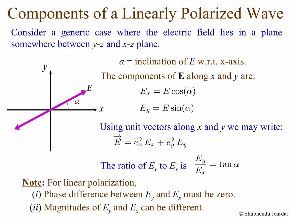
Note: For linear polarization, (i) Phase difference between Ey and Ex must be zero. (ii) Magnitudes of Ey and Ex can be different.
Using unit vectors along x and y we may write:
The ratio of Ey to Ex is
Consider a generic case where the electric field lies in a plane somewhere between y-z and x-z plane.
α = inclination of E w.r.t. x-axis.
The components of E along x and y are:
© Shubhendu Joardar
Linear Polarization: Field Component Ratio
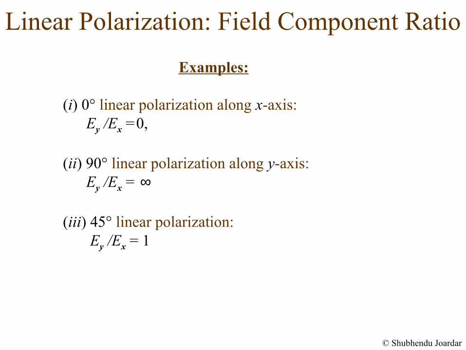
Examples:
(i) 0° linear polarization along x-axis: Ey /Ex =0,
(ii) 90° linear polarization along y-axis: Ey /Ex = ∞
(iii) 45° linear polarization: Ey /Ex = 1
© Shubhendu Joardar
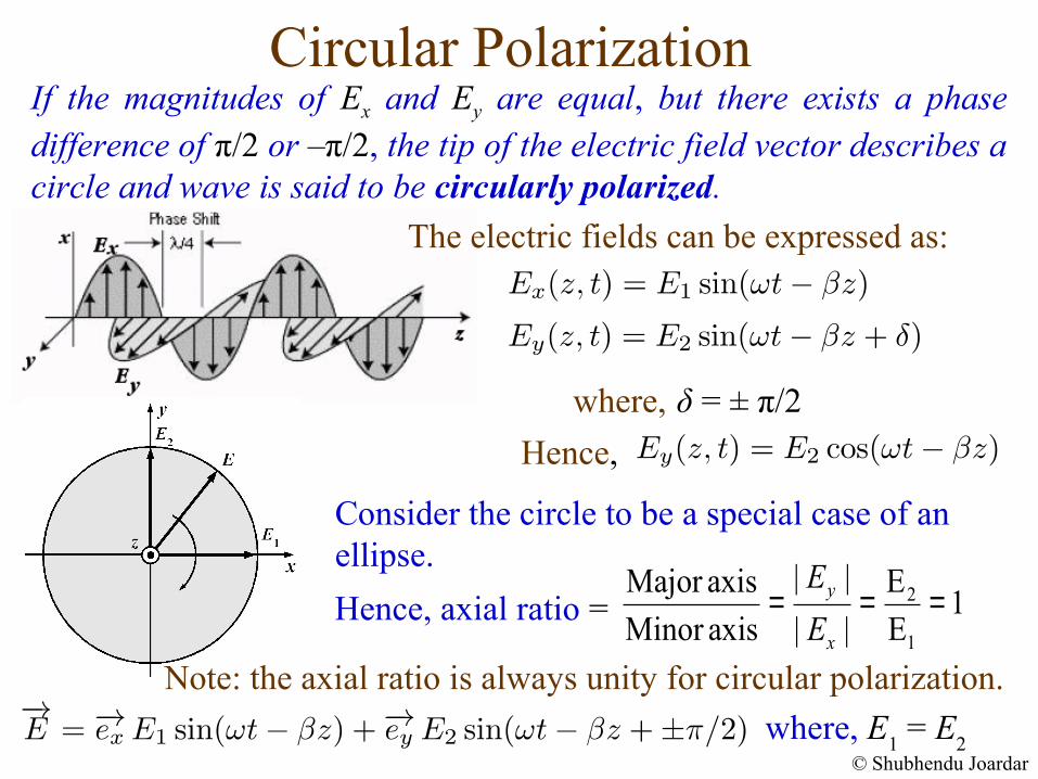
Circular PolarizationIf the magnitudes of Ex and Ey are equal, but there exists a phase difference of π/2 or –π/2, the tip of the electric field vector describes a circle and wave is said to be circularly polarized.
δ = ± π/2where,
Hence,
2
1
| | EMajor axis1
Minor axis | | Ey
x
E
E= = =Hence, axial ratio =
Consider the circle to be a special case of an ellipse.
where, E1 = E
2© Shubhendu Joardar
Note: the axial ratio is always unity for circular polarization.
The electric fields can be expressed as:
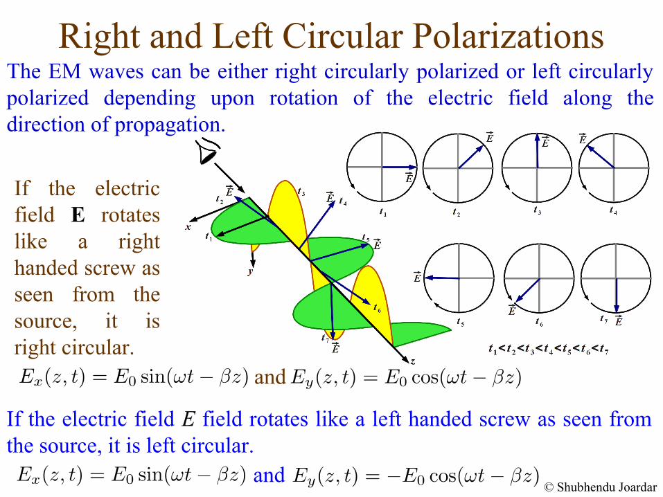
Right and Left Circular PolarizationsThe EM waves can be either right circularly polarized or left circularly polarized depending upon rotation of the electric field along the direction of propagation.
If the electric field E rotates like a right handed screw as seen from the source, it is right circular.
If the electric field E field rotates like a left handed screw as seen from the source, it is left circular.
© Shubhendu Joardar
and
and
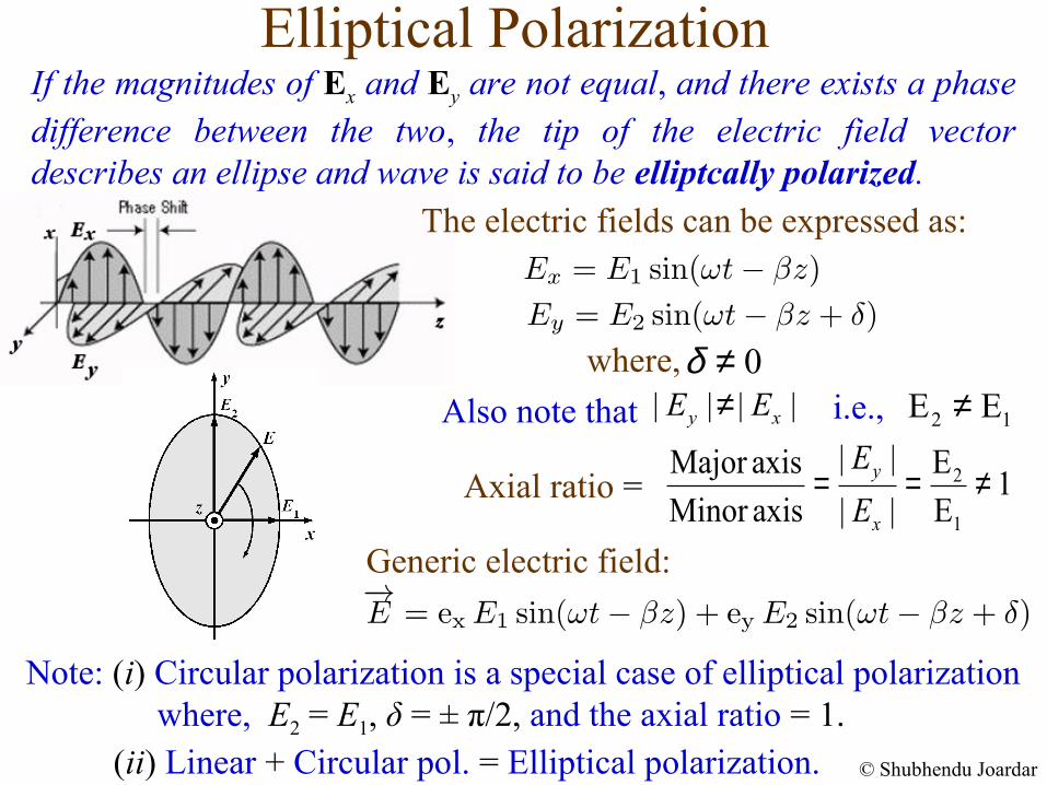
Elliptical Polarization
where,
2
1
| | EMajor axis1
Minor axis | | Ey
x
E
E= = ≠Axial ratio =
Also note that | | | |y xE E≠ 2 1E E≠i.e.,
Note: (i) Circular polarization is a special case of elliptical polarization where, E2 = E1, δ = ± π/2, and the axial ratio = 1. (ii) Linear + Circular pol. = Elliptical polarization.
0δ ≠
Generic electric field:
© Shubhendu Joardar
The electric fields can be expressed as:
If the magnitudes of Ex and Ey are not equal, and there exists a phase difference between the two, the tip of the electric field vector describes an ellipse and wave is said to be elliptcally polarized.
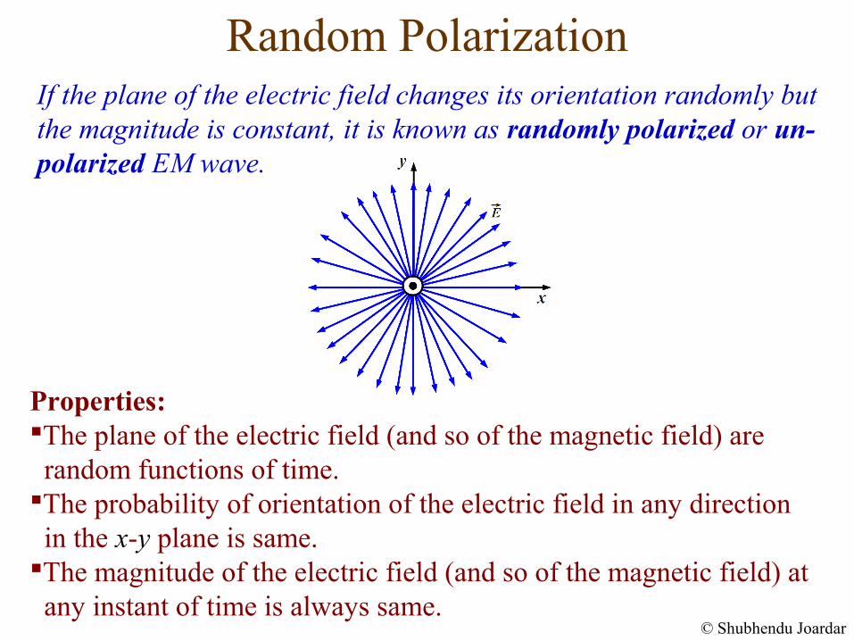
Random Polarization
Properties:The plane of the electric field (and so of the magnetic field) are random functions of time. The probability of orientation of the electric field in any direction in the x-y plane is same. The magnitude of the electric field (and so of the magnetic field) at any instant of time is always same.
If the plane of the electric field changes its orientation randomly but the magnitude is constant, it is known as randomly polarized or un-polarized EM wave.
© Shubhendu Joardar
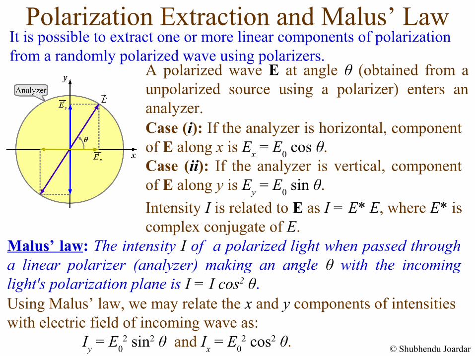
Polarization Extraction and Malus’ LawIt is possible to extract one or more linear components of polarization from a randomly polarized wave using polarizers.
Malus’ law: The intensity I of a polarized light when passed through a linear polarizer (analyzer) making an angle θ with the incoming light's polarization plane is I = I cos2 θ.Using Malus’ law, we may relate the x and y components of intensities with electric field of incoming wave as: I
y = E
02 sin2 θ and I
x = E
02 cos2 θ.
© Shubhendu Joardar
A polarized wave E at angle θ (obtained from a unpolarized source using a polarizer) enters an analyzer. Case (i): If the analyzer is horizontal, component of E along x is E
x = E
0 cos θ.
Case (ii): If the analyzer is vertical, component of E along y is E
y = E
0 sin θ.
Intensity I is related to E as I = E* E, where E* is complex conjugate of E.
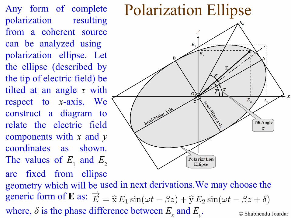
Polarization Ellipse
© Shubhendu Joardar
Any form of complete polarization resulting from a coherent source can be analyzed using polarization ellipse. Let the ellipse (described by the tip of electric field) be tilted at an angle τ with respect to x-axis. We construct a diagram to relate the electric field components with x and y coordinates as shown. The values of E
1 and E
2
are fixed from ellipse geometry which will be
where, δ is the phase difference between Ex and E
y.
used in next derivations.We may choose the generic form of E as:
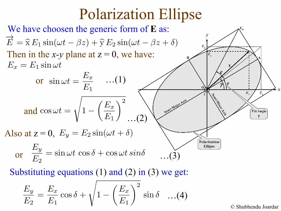
Polarization EllipseWe have choosen the generic form of E as:
Then in the x-y plane at z = 0, we have:
or
or
and
…(1)
…(2)
…(3)
Substituting equations (1) and (2) in (3) we get:
…(4)© Shubhendu Joardar
Also at z = 0,
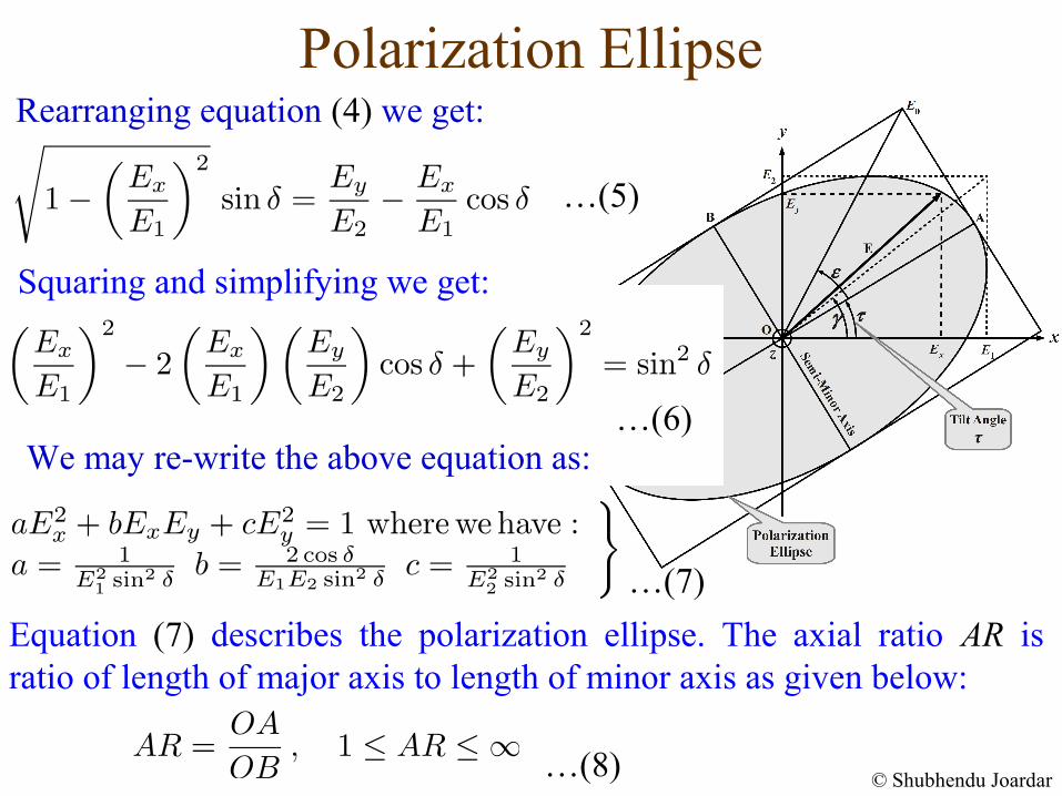
…(5)
Rearranging equation (4) we get:
Polarization Ellipse
…(6)
…(7)
We may re-write the above equation as:
…(8) © Shubhendu Joardar
Equation (7) describes the polarization ellipse. The axial ratio AR is ratio of length of major axis to length of minor axis as given below:
Squaring and simplifying we get:
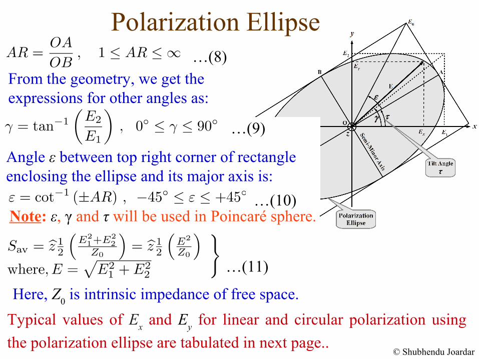
From the geometry, we get the expressions for other angles as:
Polarization Ellipse
…(9)
…(10)
…(11)
…(8)
© Shubhendu Joardar
Typical values of Ex and E
y for linear and circular polarization using
the polarization ellipse are tabulated in next page..
Here, Z0 is intrinsic impedance of free space.
Angle ε between top right corner of rectangle enclosing the ellipse and its major axis is:
Note: ε, γ and τ will be used in Poincaré sphere.
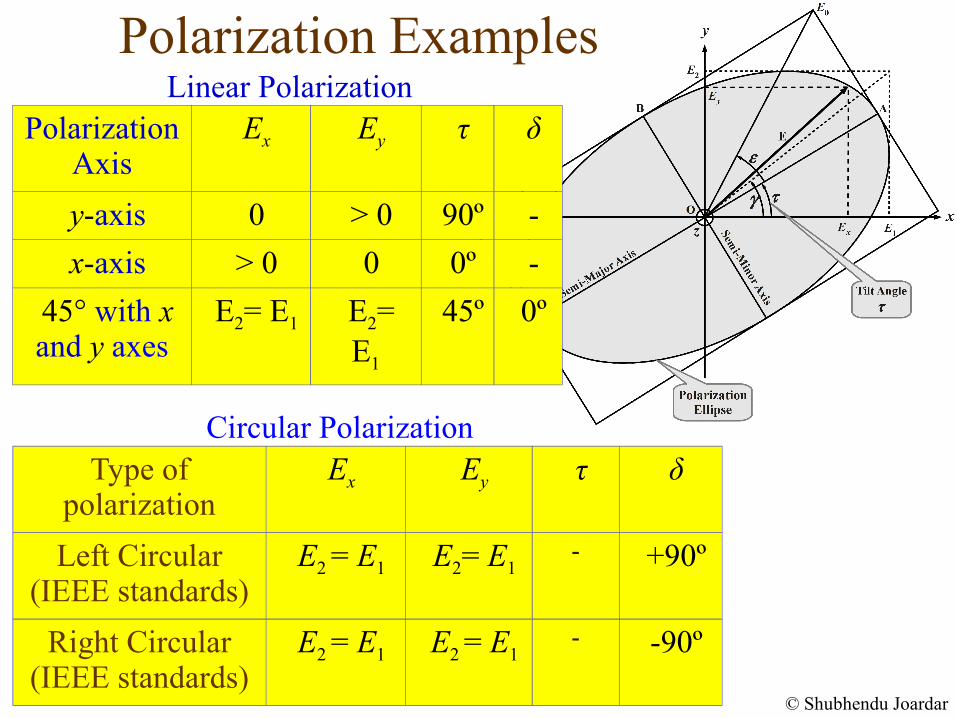
Polarization ExamplesLinear Polarization
Circular Polarization
© Shubhendu Joardar
Type of polarization
Ex Ey τ δ
Left Circular (IEEE standards)
E2 = E1 E2= E1- +90º
Right Circular (IEEE standards)
E2 = E1 E2 = E1- -90º
Polarization Axis
Ex Ey τ δ
y-axis 0 > 0 90º -
x-axis > 0 0 0º -
45° with x and y axes
E2= E1 E2= E1
45º 0º
Poincaré Sphere and Polarization Ellipse
© Shubhendu Joardar
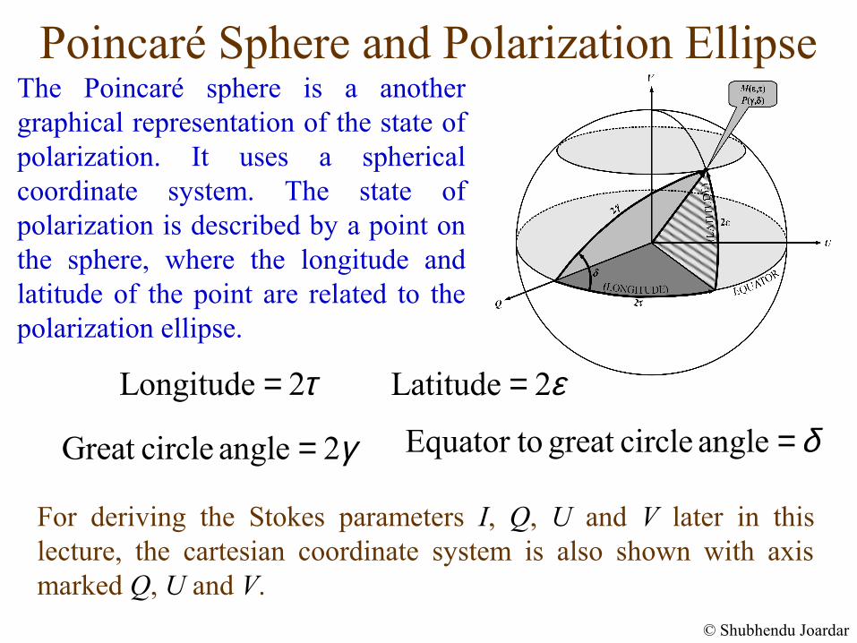
The Poincaré sphere is a another graphical representation of the state of polarization. It uses a spherical coordinate system. The state of polarization is described by a point on the sphere, where the longitude and latitude of the point are related to the polarization ellipse.
Longitude 2τ= Latitude 2ε=
Great circle angle 2γ= Equator to great circle angle δ=
For deriving the Stokes parameters I, Q, U and V later in this lecture, the cartesian coordinate system is also shown with axis marked Q, U and V.
Poincaré Sphere and Polarization Ellipse
© Shubhendu Joardar
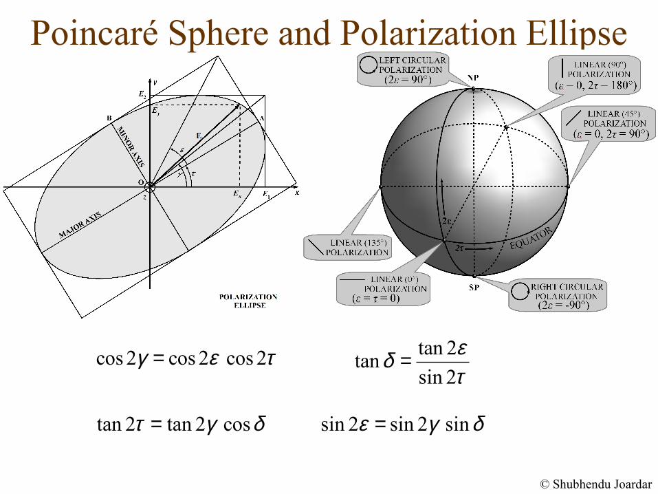
cos 2 cos 2 cos 2γ ε τ= tan 2tan
sin 2
εδτ
=
tan 2 tan 2 cosτ γ δ= sin 2 sin 2 sinε γ δ=
Poincaré Sphere and Polarization Ellipse
© Shubhendu Joardar
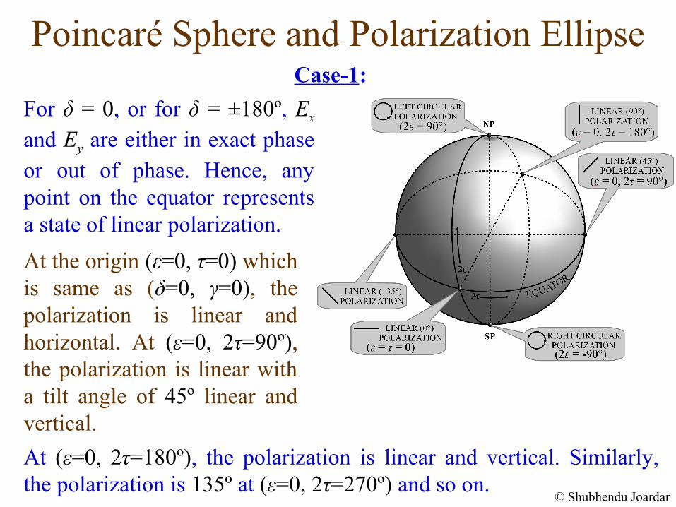
For δ = 0, or for δ = ±180º, Ex and Ey are either in exact phase or out of phase. Hence, any point on the equator represents a state of linear polarization.
At (ε=0, 2τ=180º), the polarization is linear and vertical. Similarly, the polarization is 135º at (ε=0, 2τ=270º) and so on.
Case-1:
At the origin (ε=0, τ=0) which is same as (δ=0, γ=0), the polarization is linear and horizontal. At (ε=0, 2τ=90º), the polarization is linear with a tilt angle of 45º linear and vertical.
Poincaré Sphere and Polarization Ellipse
© Shubhendu Joardar
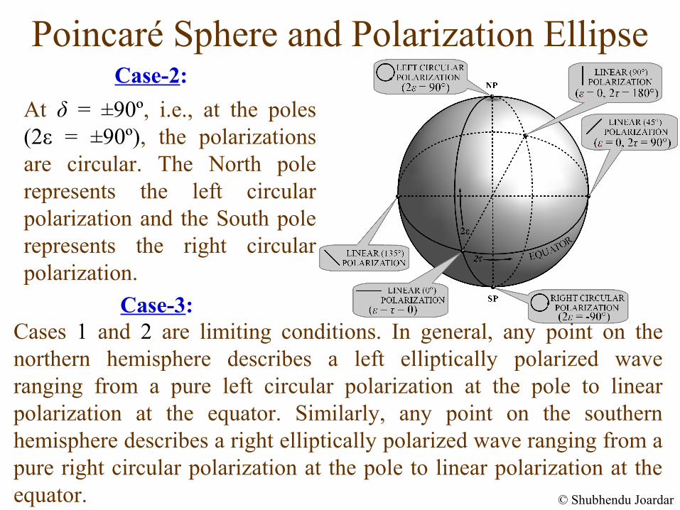
At δ = ±90º, i.e., at the poles (2ε = ±90º), the polarizations are circular. The North pole represents the left circular polarization and the South pole represents the right circular polarization.
Case-2:
Cases 1 and 2 are limiting conditions. In general, any point on the northern hemisphere describes a left elliptically polarized wave ranging from a pure left circular polarization at the pole to linear polarization at the equator. Similarly, any point on the southern hemisphere describes a right elliptically polarized wave ranging from a pure right circular polarization at the pole to linear polarization at the equator.
Case-3:
Partial Polarization & Stokes ParametersSo far we have analyzed only monochromatic waves (single frequency) where, E1, E2 and δ were assumed to be constants or slowly varying. We have also introduced random polarization and Malus’ law. We shall now use these concepts and tools for analyzing the celestial radio sources.
The celestial radio sources emit over a wide frequency range. Within a finite bandwidth Δν, the signal consists of a superposition of numerous statistically independent waves possessing variety of polarizations (randomly polarized). In most general situations, the wave is partially polarized which may be regarded as the sum of two components: (i) a completely polarized component, and (ii) a randomly polarized component. Such waves can be analyzed using Stokes parameters which we introduce next.
© Shubhendu Joardar
Stokes Parameters
Since Ex and Ey are instantaneous time functions, the polarization ellipse is valid only for a given instant of time. For an un-polarized wave, it is not possible to obtain the instantaneous tilt angle τ or the axial ratio.
© Shubhendu Joardar
To overcome these limitations Stokes parameters are used, which is a set of four time averaged components (I, Q, U, V) obtained from the wave and can be related to the polarization ellipse. From its properties, (i) if two waves have identical Stokes parameters, the waves are identical, and (ii) if several independent waves propagating in the same direction are superimposed, the Stokes parameters of the resultant wave is the sum of Stokes parameters of individual waves.
Limitations of Polarization ellipse
We shall first investigate them for the following three cases: (i) Completely polarized waves. (ii) Completely un-polarized waves. (iii) Partially polarized waves.
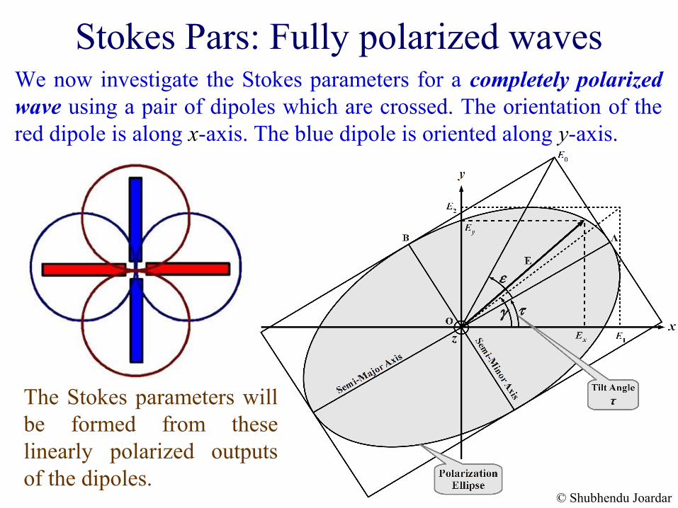
Stokes Pars: Fully polarized wavesWe now investigate the Stokes parameters for a completely polarized wave using a pair of dipoles which are crossed. The orientation of the red dipole is along x-axis. The blue dipole is oriented along y-axis.
The Stokes parameters will be formed from these linearly polarized outputs of the dipoles.
© Shubhendu Joardar
Stokes Pars: Fully polarized waves
© Shubhendu Joardar
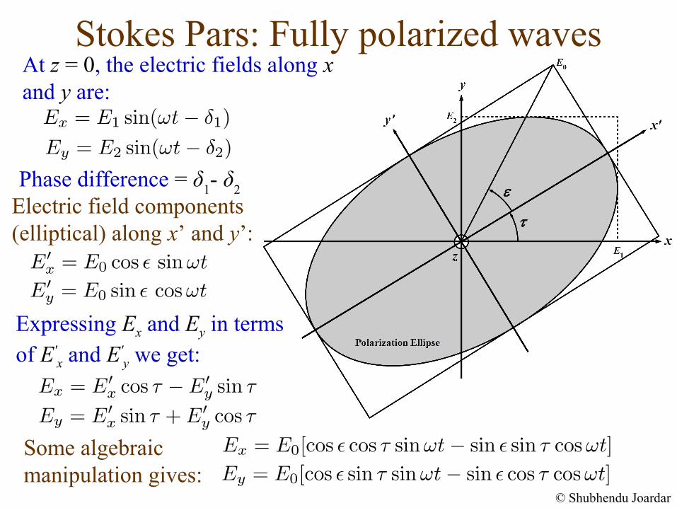
At z = 0, the electric fields along x and y are:
Electric field components (elliptical) along x’ and y’:
Expressing Ex and Ey in terms of E'
x and E'y we get:
Some algebraic manipulation gives:
Phase difference = δ1- δ
2
Stokes Pars: Fully polarized waves
© Shubhendu Joardar
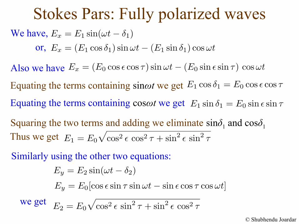
We have,
Also we have
Equating the terms containing sinωt we get
Equating the terms containing cosωt we get
Squaring the two terms and adding we eliminate sinδ1 and cosδ1
Thus we get
Similarly using the other two equations:
we get
or,
Stokes Pars: Fully polarized waves
© Shubhendu Joardar
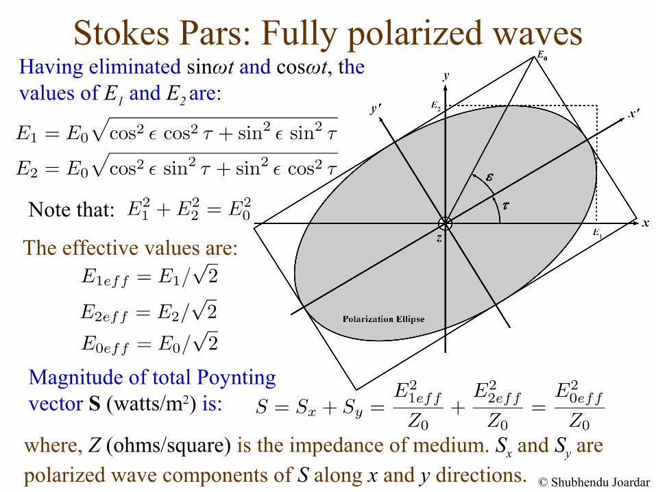
Having eliminated sinωt and cosωt, the values of E1 and E2 are:
Magnitude of total Poynting vector S (watts/m2) is:
The effective values are:
where, Z (ohms/square) is the impedance of medium. Sx and Sy are polarized wave components of S along x and y directions.
Note that:
© Shubhendu Joardar
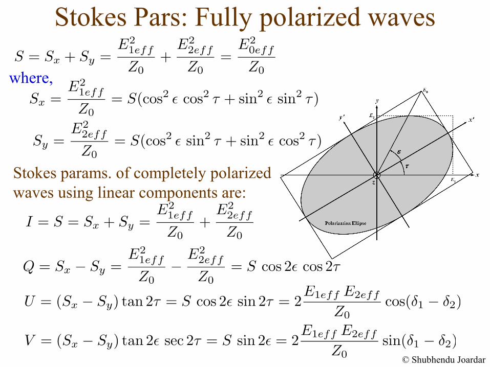
where,
Stokes params. of completely polarized waves using linear components are:
Stokes Pars: Fully polarized waves
Stokes Pars: Fully polarized waves
© Shubhendu Joardar
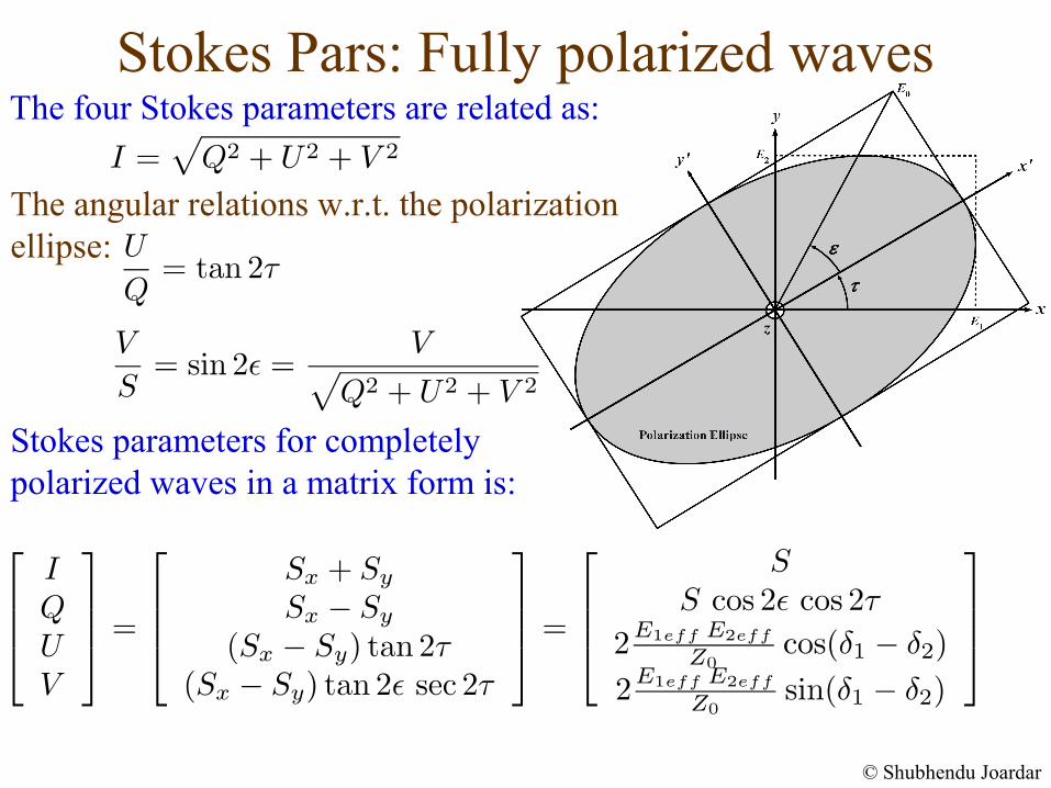
The four Stokes parameters are related as:
The angular relations w.r.t. the polarization ellipse:
Stokes parameters for completely polarized waves in a matrix form is:
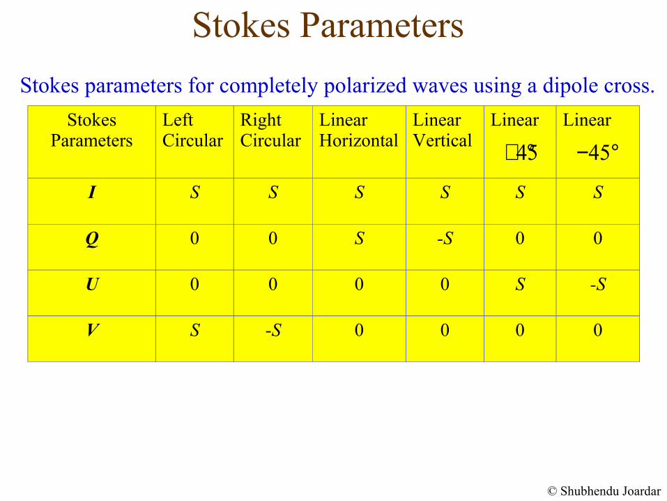
Stokes Parameters
© Shubhendu Joardar
StokesParameters
Left Circular
RightCircular
Linear Horizontal
Linear Vertical
Linear Linear
I S S S S S S
Q 0 0 S -S 0 0
U 0 0 0 0 S -S
V S -S 0 0 0 0
Stokes parameters for completely polarized waves using a dipole cross.
45+ ° 45− °
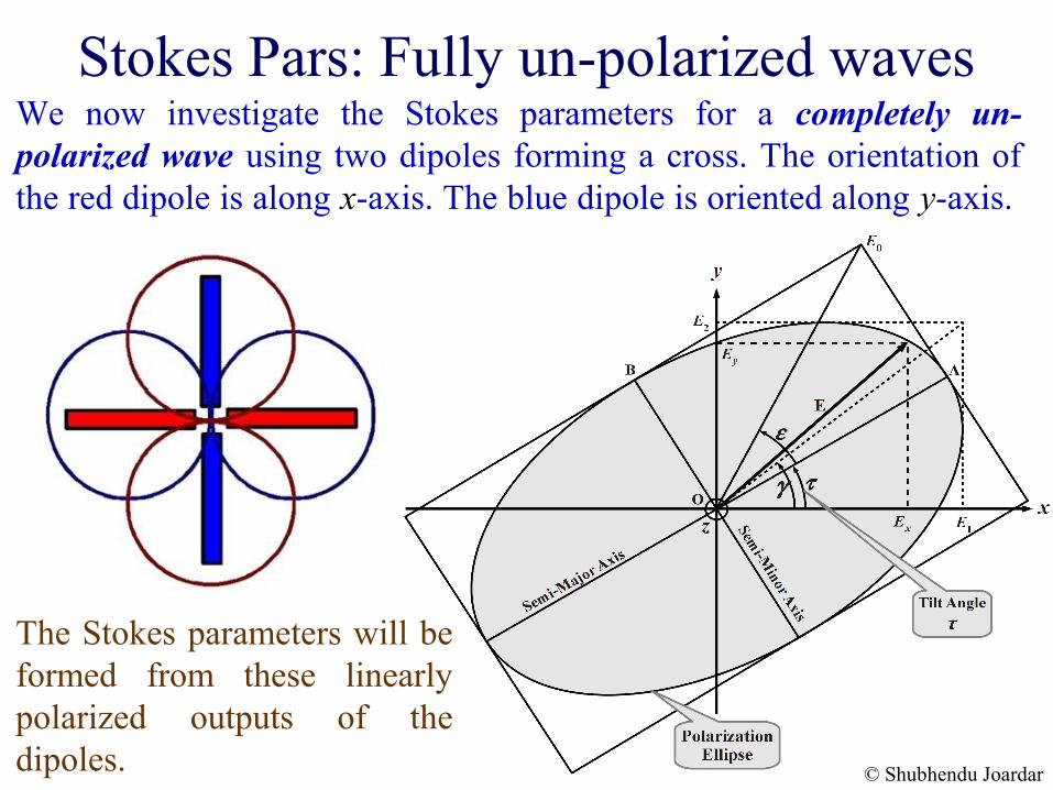
Stokes Pars: Fully un-polarized wavesWe now investigate the Stokes parameters for a completely un-polarized wave using two dipoles forming a cross. The orientation of the red dipole is along x-axis. The blue dipole is oriented along y-axis.
The Stokes parameters will be formed from these linearly polarized outputs of the dipoles. © Shubhendu Joardar
© Shubhendu Joardar
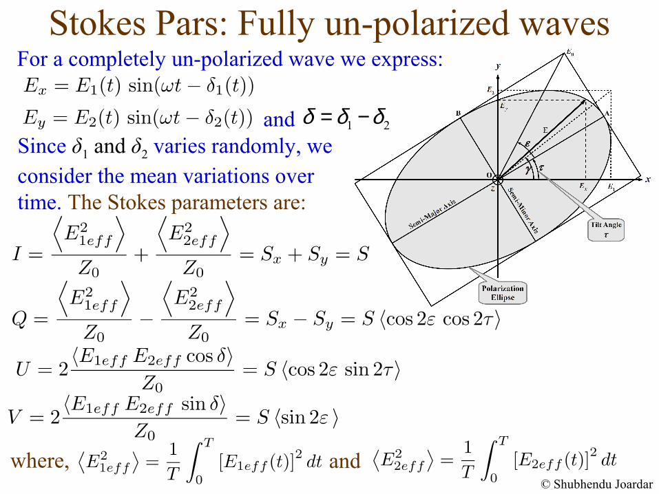
1 2δ δ δ= −
For a completely un-polarized wave we express:
Since δ1 and δ2 varies randomly, we consider the mean variations over time. The Stokes parameters are:
Stokes Pars: Fully un-polarized waves
where,
and
and
© Shubhendu Joardar
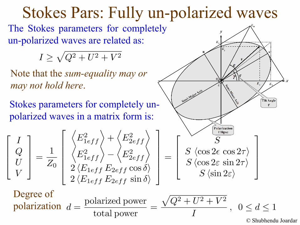
The Stokes parameters for completely un-polarized waves are related as:
Stokes Pars: Fully un-polarized waves
Stokes parameters for completely un-polarized waves in a matrix form is:
Note that the sum-equality may or may not hold here.
Degree of polarization
Stokes Pars: Fully un-polarized waves
© Shubhendu Joardar
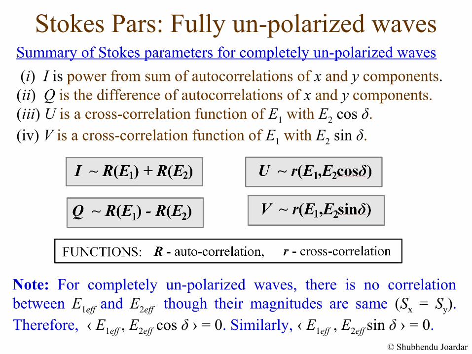
(i) I is power from sum of autocorrelations of x and y components. (ii) Q is the difference of autocorrelations of x and y components. (iii) U is a cross-correlation function of E1 with E2 cos δ. (iv) V is a cross-correlation function of E1 with E2 sin δ.
Summary of Stokes parameters for completely un-polarized waves
Note: For completely un-polarized waves, there is no correlation between E1eff and E2eff though their magnitudes are same (Sx = Sy). Therefore, ‹ E1eff , E2eff cos δ › = 0. Similarly, ‹ E1eff , E2eff sin δ › = 0.
Stokes Parameters
© Shubhendu Joardar
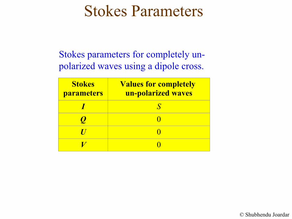
Stokes parameters for completely un-polarized waves using a dipole cross.
Stokes parameters
Values for completely un-polarized waves
I S
Q 0
U 0
V 0
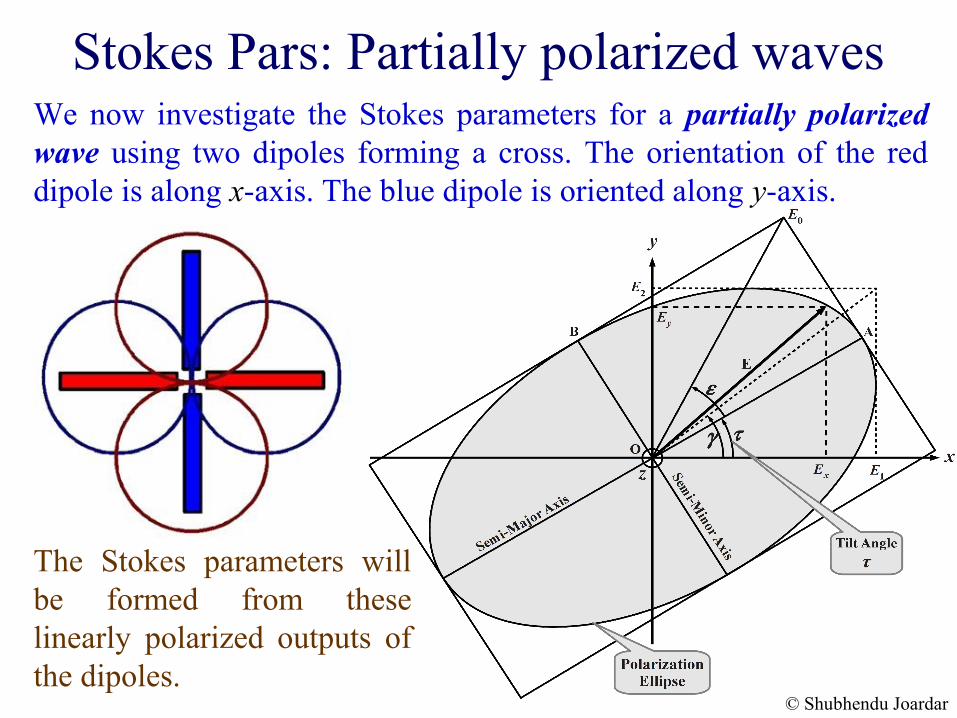
Stokes Pars: Partially polarized wavesWe now investigate the Stokes parameters for a partially polarized wave using two dipoles forming a cross. The orientation of the red dipole is along x-axis. The blue dipole is oriented along y-axis.
The Stokes parameters will be formed from these linearly polarized outputs of the dipoles.
© Shubhendu Joardar
© Shubhendu Joardar
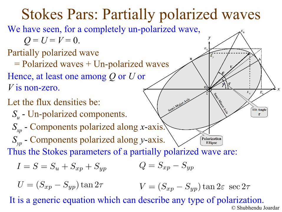
Partially polarized wave = Polarized waves + Un-polarized wavesHence, at least one among Q or U or V is non-zero.
We have seen, for a completely un-polarized wave, Q = U = V = 0.
Su - Un-polarized components. Sxp - Components polarized along x-axis.Syp - Components polarized along y-axis.
Let the flux densities be:
Thus the Stokes parameters of a partially polarized wave are:
It is a generic equation which can describe any type of polarization.
Stokes Pars: Partially polarized waves
© Shubhendu Joardar
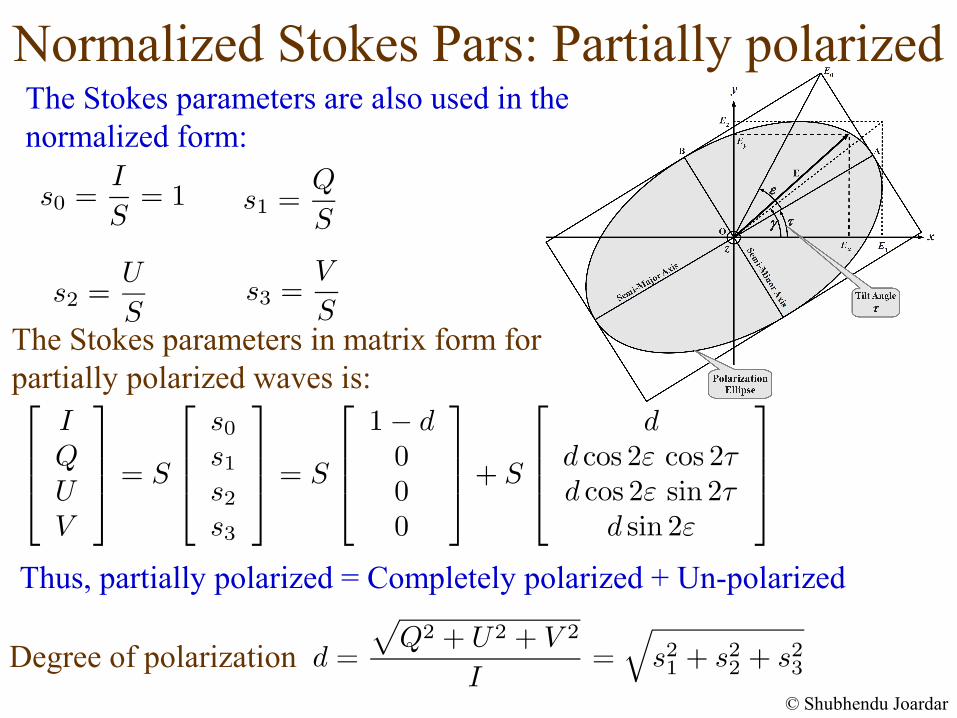
The Stokes parameters are also used in the normalized form:
Normalized Stokes Pars: Partially polarized
Thus, partially polarized = Completely polarized + Un-polarized
Degree of polarization
The Stokes parameters in matrix form for partially polarized waves is:
Stokes Pars: Alternative Approach
© Shubhendu Joardar
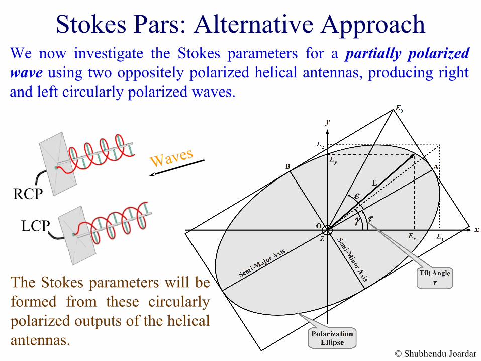
We now investigate the Stokes parameters for a partially polarized wave using two oppositely polarized helical antennas, producing right and left circularly polarized waves.
Waves
RCP
LCP
The Stokes parameters will be formed from these circularly polarized outputs of the helical antennas.
© Shubhendu Joardar
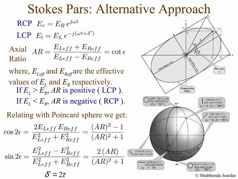
RCP
LCP
AxialRatio
If EL > ER, AR is positive ( LCP ).If EL < ER, AR is negative ( RCP ).
Relating with Poincaré sphere we get:
2δ τ′ =
Stokes Pars: Alternative Approach
where, ELeff and EReff are the effective values of EL and ER respectively.
© Shubhendu Joardar
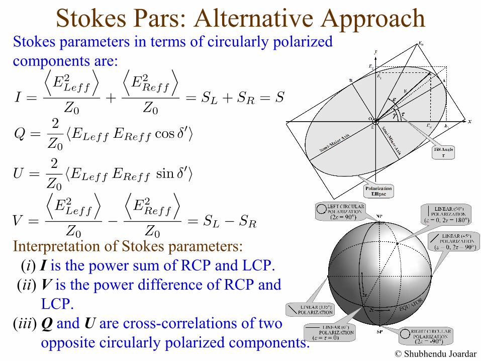
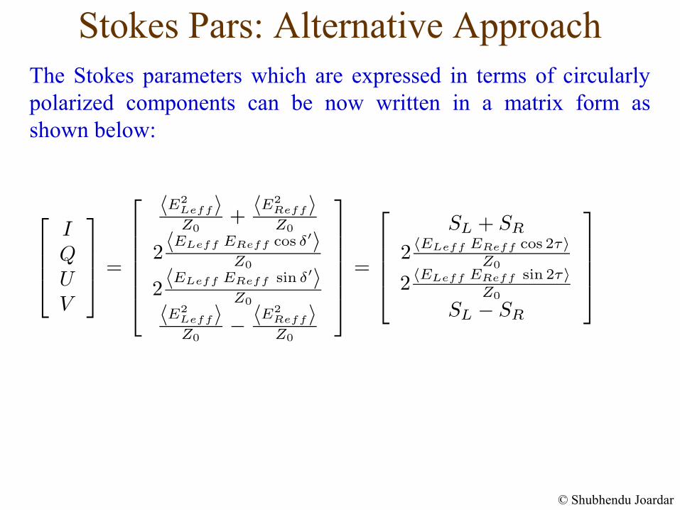
Stokes Pars: Alternative ApproachStokes parameters in terms of circularly polarized components are:
Interpretation of Stokes parameters: (i) I is the power sum of RCP and LCP. (ii) V is the power difference of RCP and LCP. (iii) Q and U are cross-correlations of two opposite circularly polarized components.
© Shubhendu Joardar
The Stokes parameters which are expressed in terms of circularly polarized components can be now written in a matrix form as shown below:
Stokes Pars: Alternative Approach
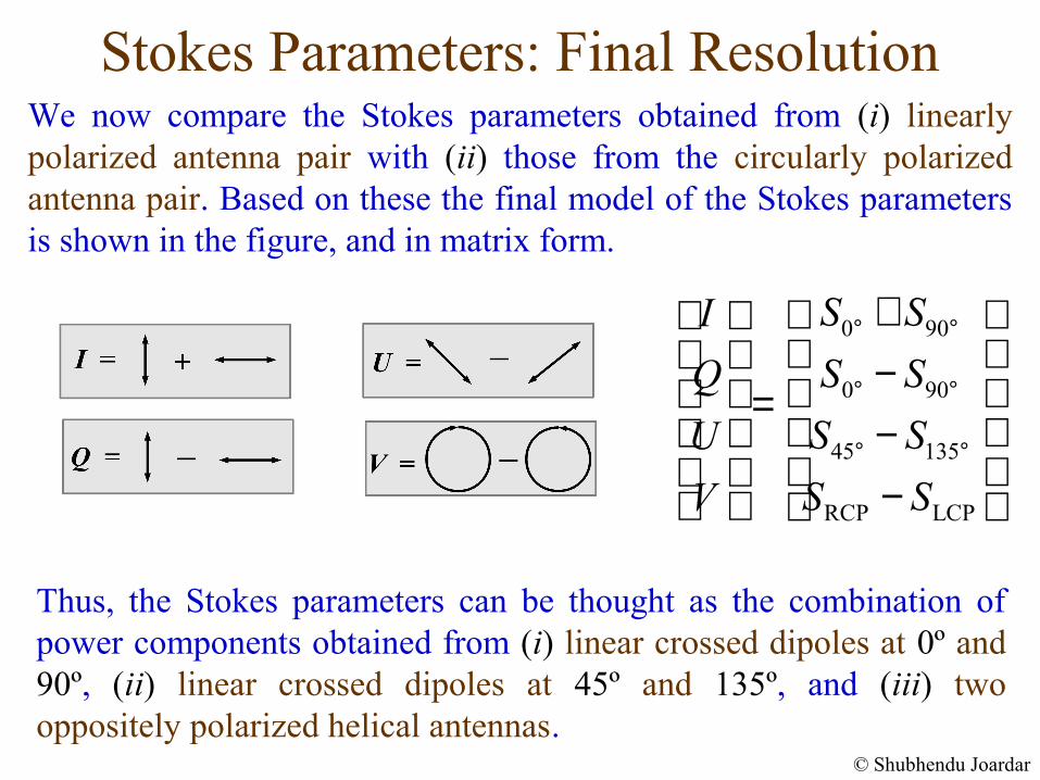
Stokes Parameters: Final ResolutionWe now compare the Stokes parameters obtained from (i) linearly polarized antenna pair with (ii) those from the circularly polarized antenna pair. Based on these the final model of the Stokes parameters is shown in the figure, and in matrix form.
© Shubhendu Joardar
Thus, the Stokes parameters can be thought as the combination of power components obtained from (i) linear crossed dipoles at 0º and 90º, (ii) linear crossed dipoles at 45º and 135º, and (iii) two oppositely polarized helical antennas.
0 90
0 90
45 135
RCP LCP
S SI
S SQ
S SU
S SV
° °
° °
° °
+ − = − −
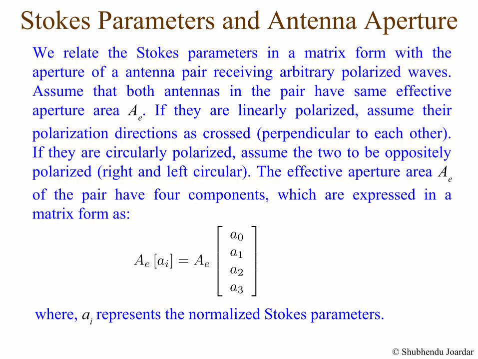
Stokes Parameters and Antenna ApertureWe relate the Stokes parameters in a matrix form with the aperture of a antenna pair receiving arbitrary polarized waves. Assume that both antennas in the pair have same effective aperture area A
e. If they are linearly polarized, assume their
polarization directions as crossed (perpendicular to each other). If they are circularly polarized, assume the two to be oppositely polarized (right and left circular). The effective aperture area A
e
of the pair have four components, which are expressed in a matrix form as:
where, ai represents the normalized Stokes parameters.
© Shubhendu Joardar
Stokes Pars: Antenna in Tranmitting Mode
© Shubhendu Joardar
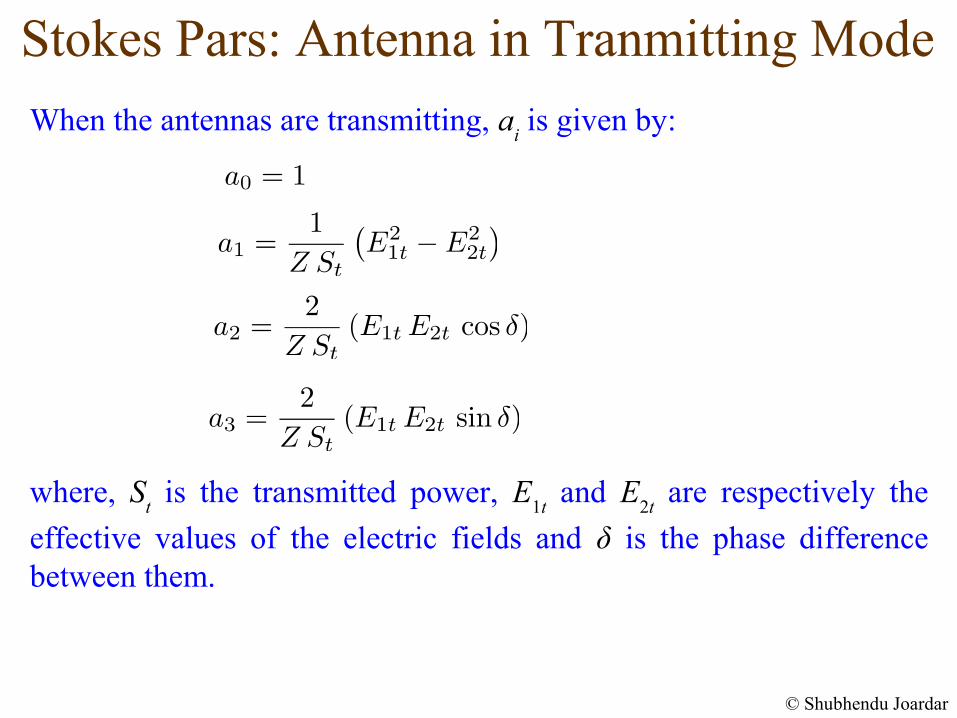
When the antennas are transmitting, ai is given by:
where, St is the transmitted power, E
1t and E
2t are respectively the
effective values of the electric fields and δ is the phase difference between them.
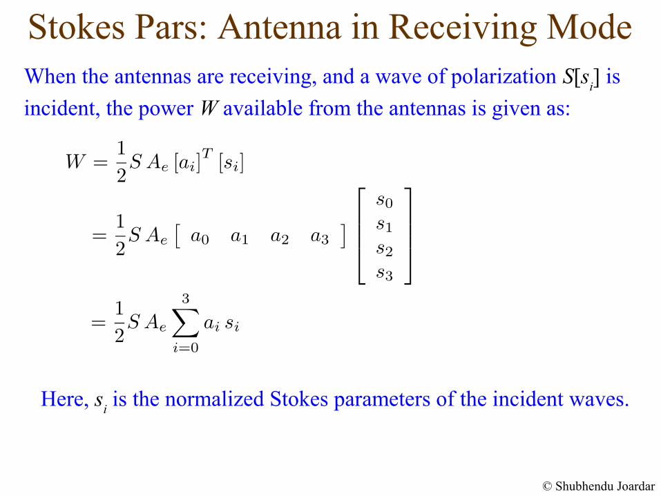
Stokes Pars: Antenna in Receiving ModeWhen the antennas are receiving, and a wave of polarization S[s
i] is
incident, the power W available from the antennas is given as:
© Shubhendu Joardar
Here, si is the normalized Stokes parameters of the incident waves.
Stokes Parameters for Interferometers
© Shubhendu Joardar
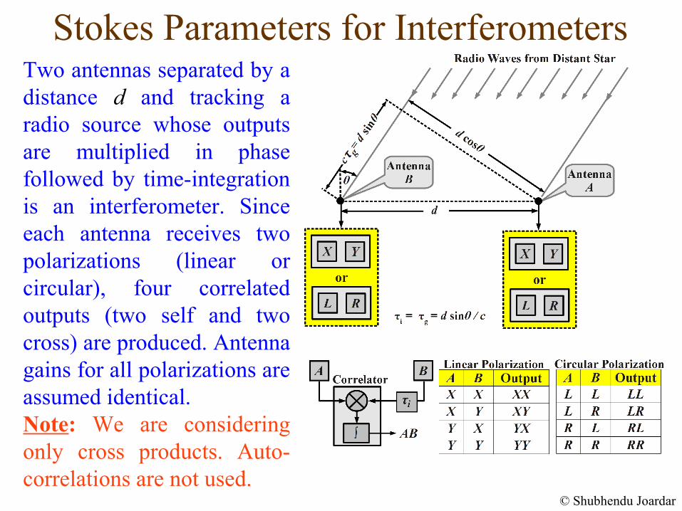
Two antennas separated by a distance d and tracking a radio source whose outputs are multiplied in phase followed by time-integration is an interferometer. Since each antenna receives two polarizations (linear or circular), four correlated outputs (two self and two cross) are produced. Antenna gains for all polarizations are assumed identical. Note: We are considering only cross products. Auto-correlations are not used.
Stokes Parameters: Linearly Polarized Interferometers
© Shubhendu Joardar
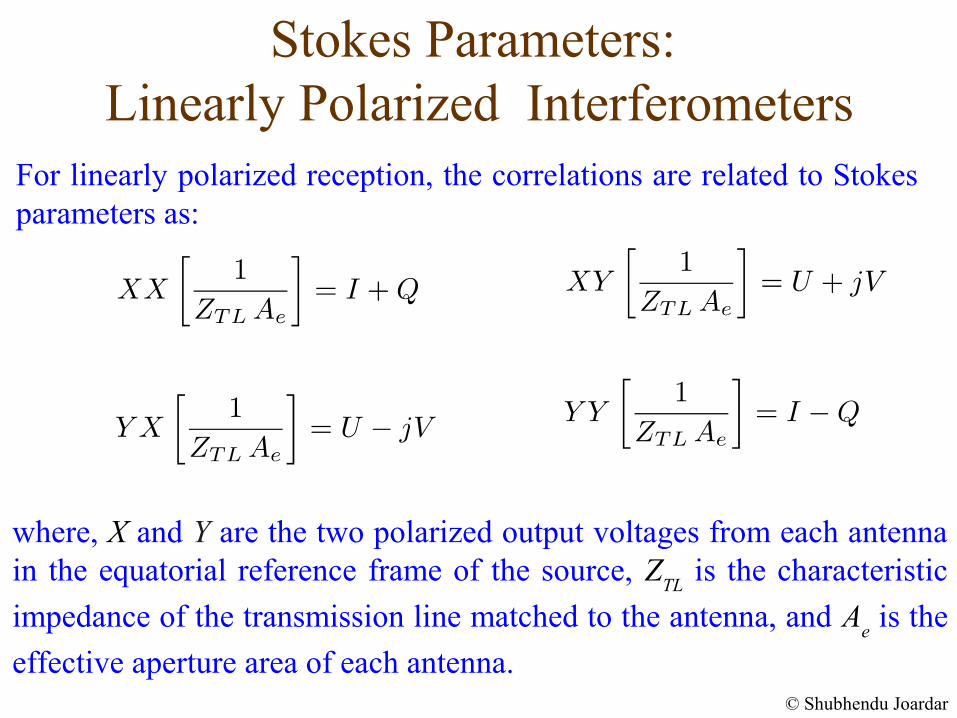
where, X and Y are the two polarized output voltages from each antenna in the equatorial reference frame of the source, Z
TL is the characteristic
impedance of the transmission line matched to the antenna, and Ae is the
effective aperture area of each antenna.
For linearly polarized reception, the correlations are related to Stokes parameters as:
Stokes Parameters: Circularly Polarized Interferometers
© Shubhendu Joardar
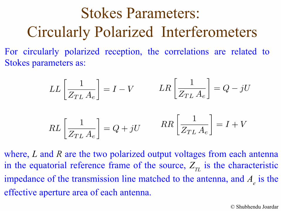
For circularly polarized reception, the correlations are related to Stokes parameters as:
where, L and R are the two polarized output voltages from each antenna in the equatorial reference frame of the source, Z
TL is the characteristic
impedance of the transmission line matched to the antenna, and Ae is the
effective aperture area of each antenna.
Important NoteIn the equations we have shown for interferometer, we have assumed the antennas as ideal. Practically, antenna-feeds are not perfectly polarized. Hence an unpolarized source appears as polarized when observed using them. Furthermore, while tracking the source, the antenna-feeds rotate relative to the equatorial frame of the source. Thus, the above equations have to be modified accordingly before usage. A polarization calibration is generally done to remove both these effects. After calibration, only the source polarization information remains in the data.
Stokes Parameters for Interferometers...
© Shubhendu Joardar
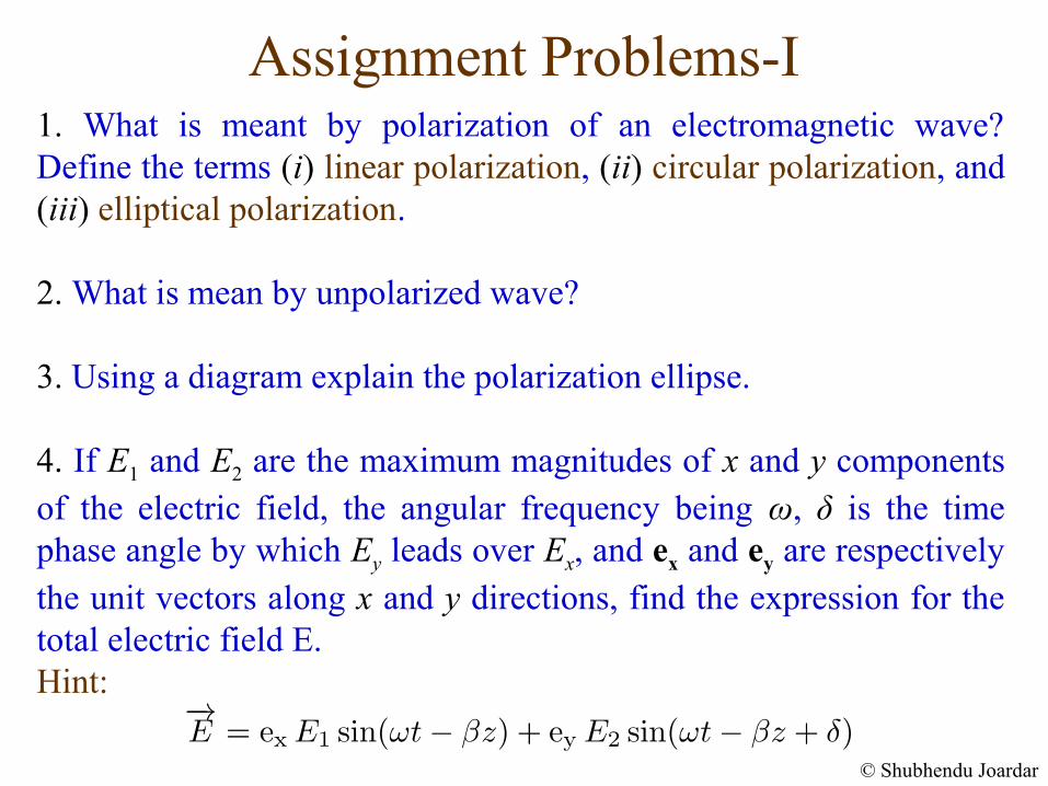
Assignment Problems-I1. What is meant by polarization of an electromagnetic wave? Define the terms (i) linear polarization, (ii) circular polarization, and (iii) elliptical polarization.
2. What is mean by unpolarized wave?
3. Using a diagram explain the polarization ellipse.
4. If E1 and E2 are the maximum magnitudes of x and y components of the electric field, the angular frequency being ω, δ is the time phase angle by which Ey leads over Ex, and ex and ey are respectively the unit vectors along x and y directions, find the expression for the total electric field E. Hint:
© Shubhendu Joardar
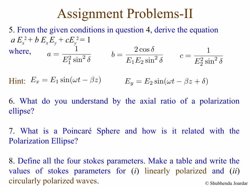
Assignment Problems-II5. From the given conditions in question 4, derive the equation a Ex
2 + b Ex Ey + cEy2 = 1
where,
Hint:
6. What do you understand by the axial ratio of a polarization ellipse?
7. What is a Poincaré Sphere and how is it related with the Polarization Ellipse?
8. Define all the four stokes parameters. Make a table and write the values of stokes parameters for (i) linearly polarized and (ii) circularly polarized waves. © Shubhendu Joardar
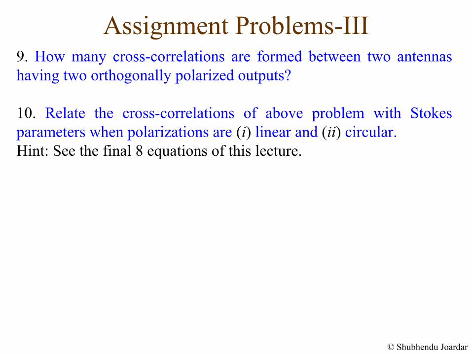
Assignment Problems-III9. How many cross-correlations are formed between two antennas having two orthogonally polarized outputs?
10. Relate the cross-correlations of above problem with Stokes parameters when polarizations are (i) linear and (ii) circular. Hint: See the final 8 equations of this lecture.
© Shubhendu Joardar

THANK YOU