Embed Size (px)
Citation preview
Polarity Montages
Localization
Bassel Abou-Khalil, M.D.

I have no financial relationships to disclose that are relative to the
content of my presentation
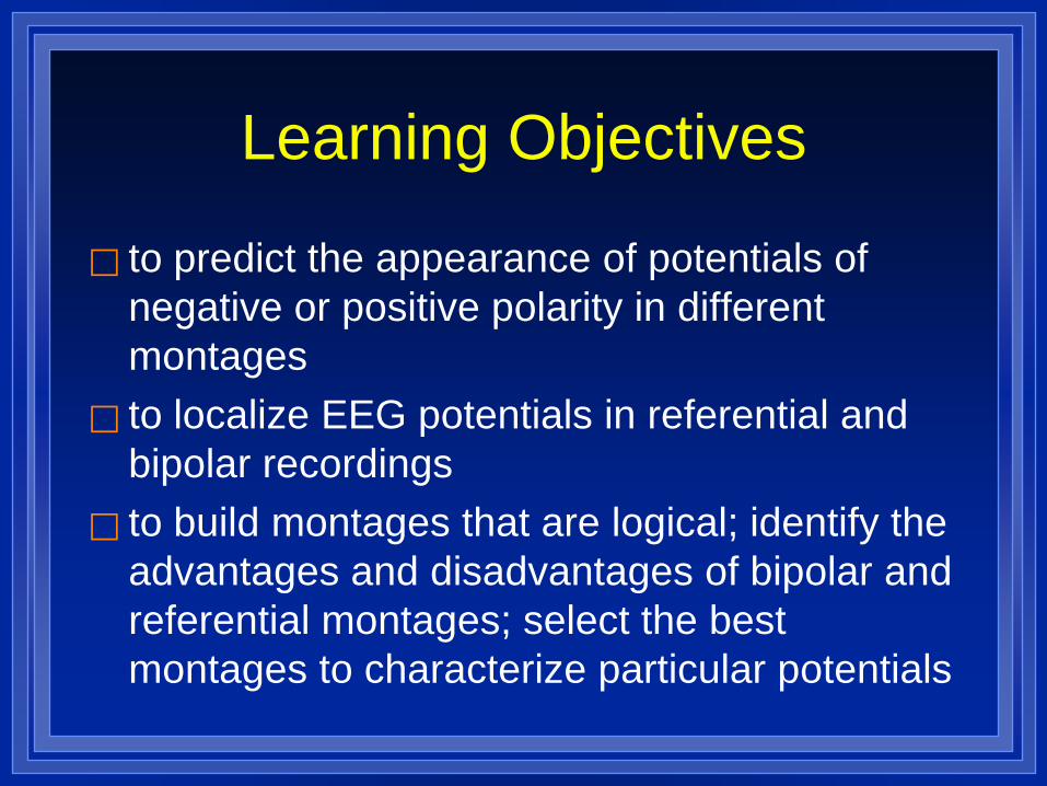
Learning Objectives
to predict the appearance of potentials of negative or positive polarity in different montages
to localize EEG potentials in referential and bipolar recordings
to build montages that are logical; identify the advantages and disadvantages of bipolar and referential montages; select the best montages to characterize particular potentials

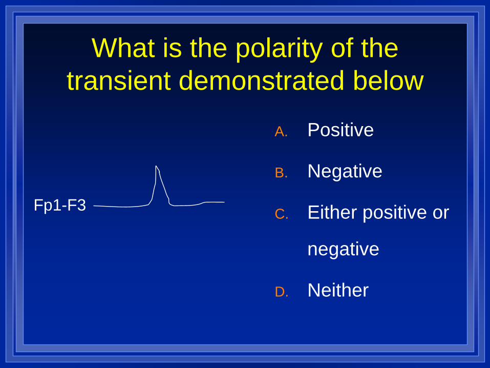
What is the polarity of the transient demonstrated below
A. Positive
B. Negative
C. Either positive or
negative
D. Neither
Fp1-F3
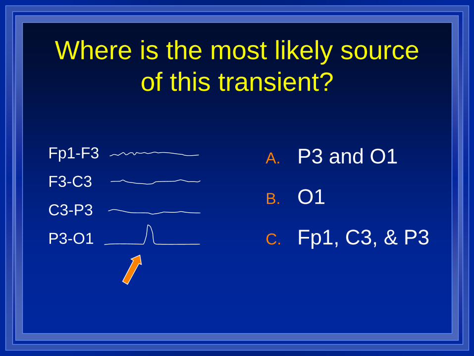
Where is the most likely source of this transient?
A. P3 and O1
B. O1
C. Fp1, C3, & P3
Fp1-F3
F3-C3
C3-P3
P3-O1
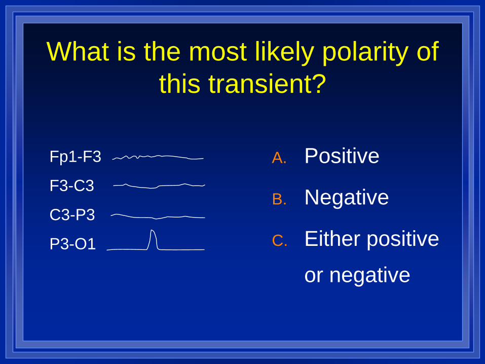
What is the most likely polarity of this transient?
A. Positive
B. Negative
C. Either positive
or negative
Fp1-F3
F3-C3
C3-P3
P3-O1
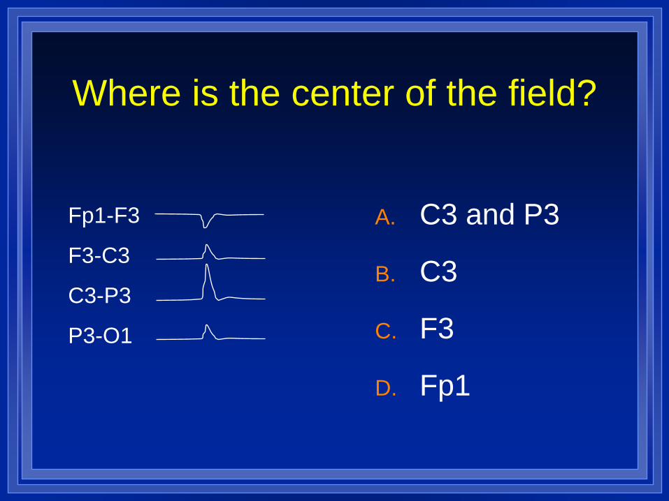
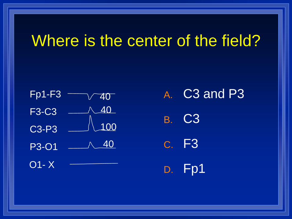
Where is the center of the field?
A. C3 and P3
B. C3
C. F3
D. Fp1
Fp1-F3
F3-C3
C3-P3
P3-O1
The EEG
The EEG measures potential differences between electrode positions on the scalp.
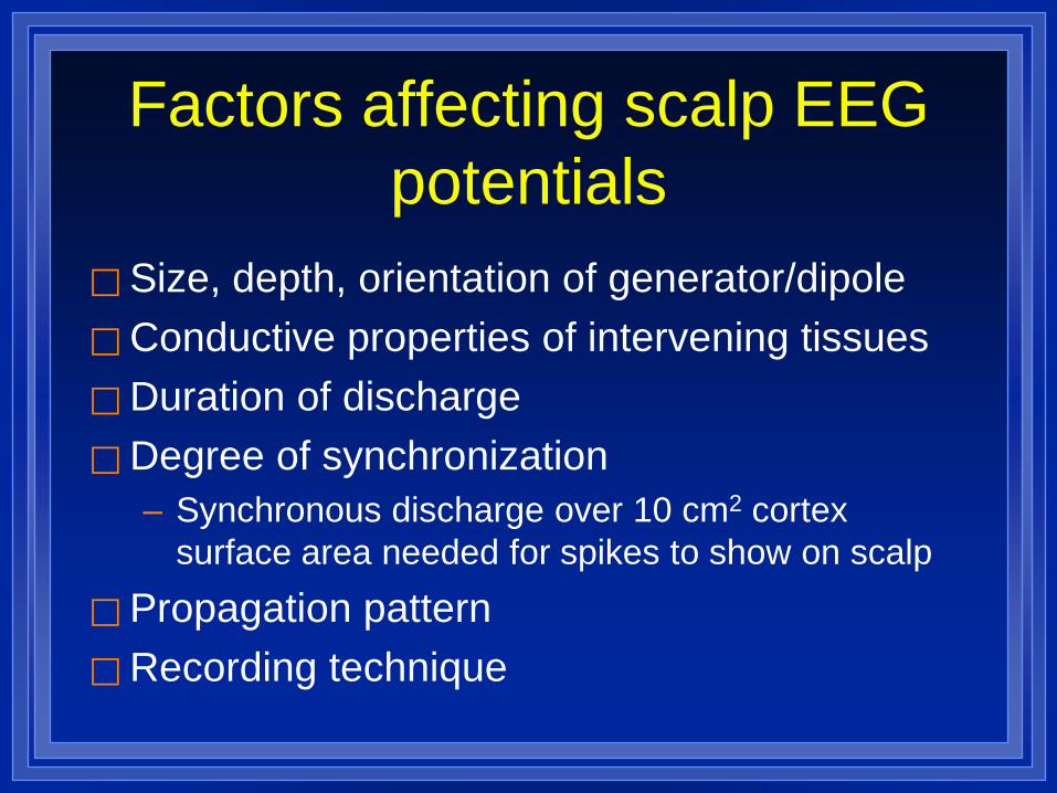
Factors affecting scalp EEG potentials
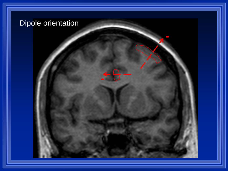
Size, depth, orientation of generator/dipole Conductive properties of intervening tissues Duration of discharge Degree of synchronization
– Synchronous discharge over 10 cm2 cortex surface area needed for spikes to show on scalp
Propagation pattern Recording technique
-
-
Dipole orientation
EEG at scalp Amplitude depends on:
– intensity of electrical potential – distance of potential – spatial orientation of dipole – resistance and capacitance of structures between
source and electrodes Amplitude may decrease with:
– increased impedance – decreased impedance resulting in current shunt
EEG at scalp
Potential changes are favored if they: – occur near the recording electrodes – are generated in a large area of tissue – rise and fall at a slow speed
Potentials generated at a distant site are rarely recorded, but those of high amplitude and low frequency may be transmitted through volume conduction
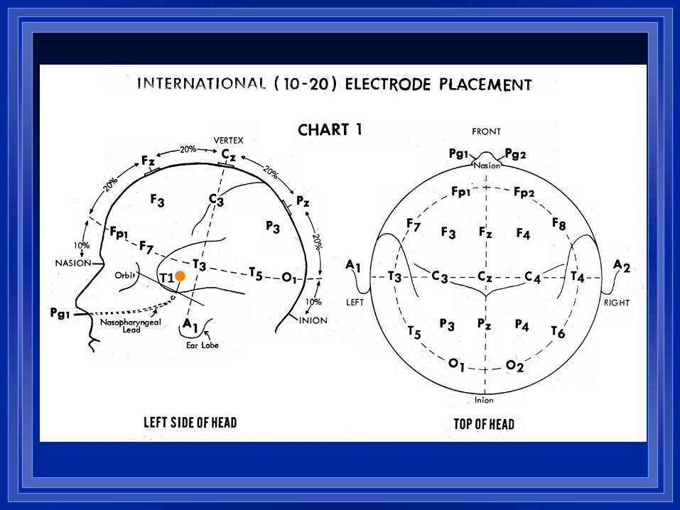
T1
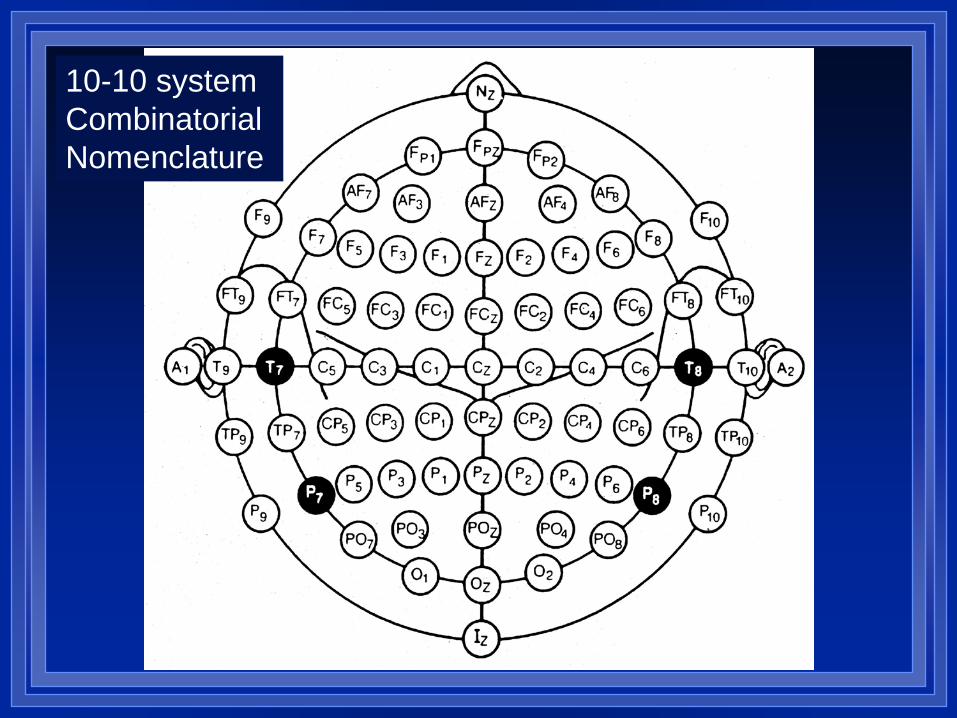
10-10 system Combinatorial Nomenclature
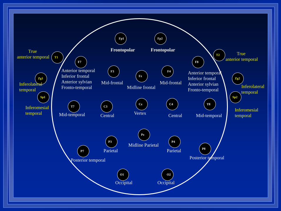
Frontopolar Frontopolar
Mid-frontal Mid-frontal Midline frontal
Vertex Central Central
Parietal Parietal Midline Parietal
Occipital Occipital
Mid-temporal Mid-temporal
Anterior temporal Inferior frontal Anterior sylvian Fronto-temporal
Posterior temporal Posterior temporal
Anterior temporal Inferior frontal Anterior sylvian Fronto-temporal
Fp1
F7
F3 F4
F8
O1 O2
T7
Fp2
C3 Cz C4
Fz
T8
P4
P8
P3
Pz
P7
Zg1
Sp1
Zg2
Sp2
Inferolateral temporal
Inferomesial temporal
Inferolateral temporal
Inferomesial temporal
T1 T2
True anterior temporal
True anterior temporal
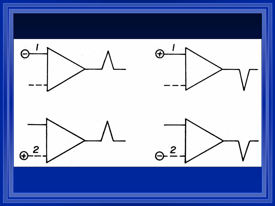
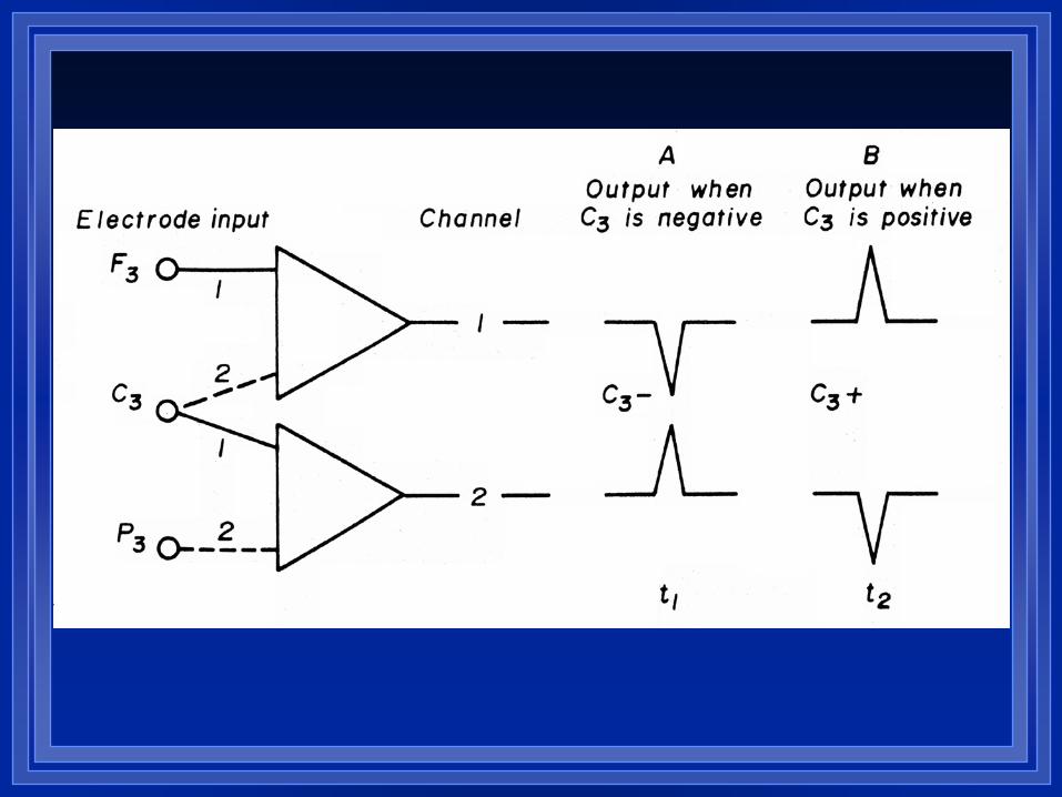
POLARITY- LOCALIZATION
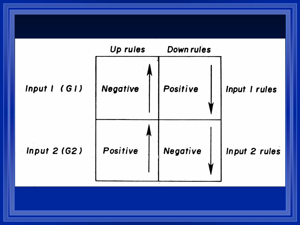
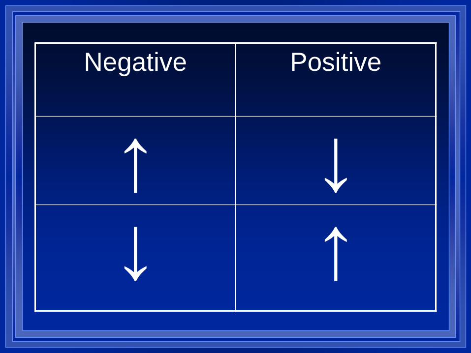
Negative Positive
↑ ↓ ↓ ↑
B
C
-
+
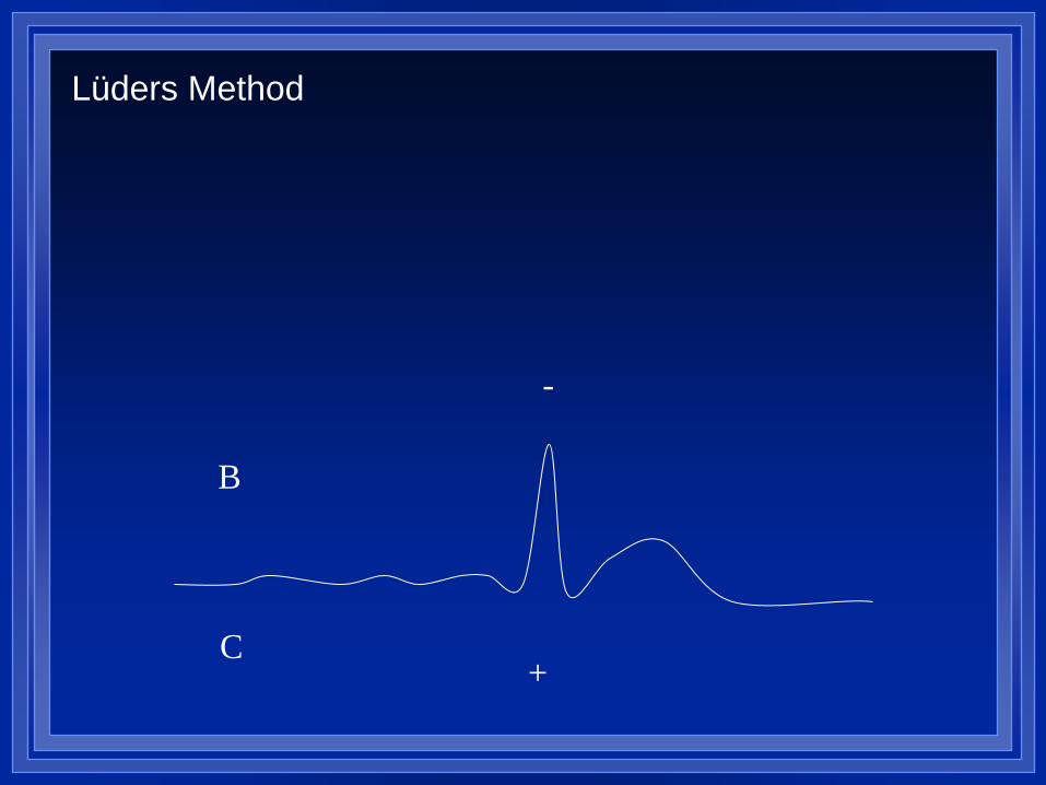
Lüders Method
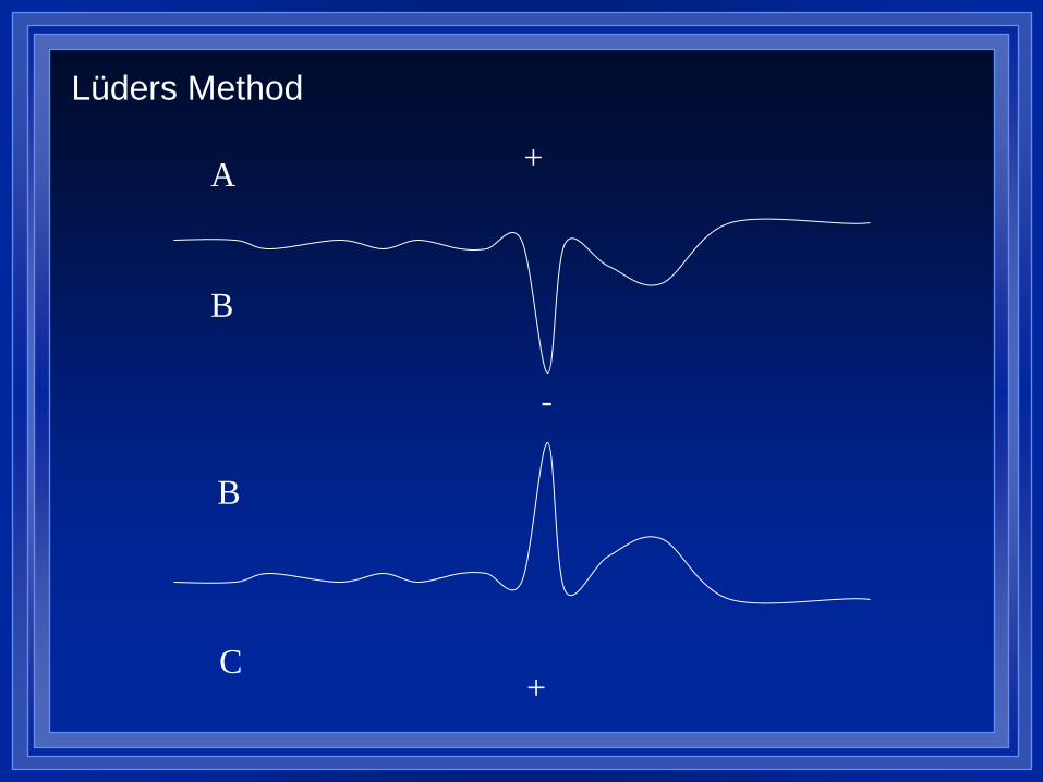
B
C
-
+
A
B
+
Lüders Method
MONTAGES- BIPOLAR
or midline
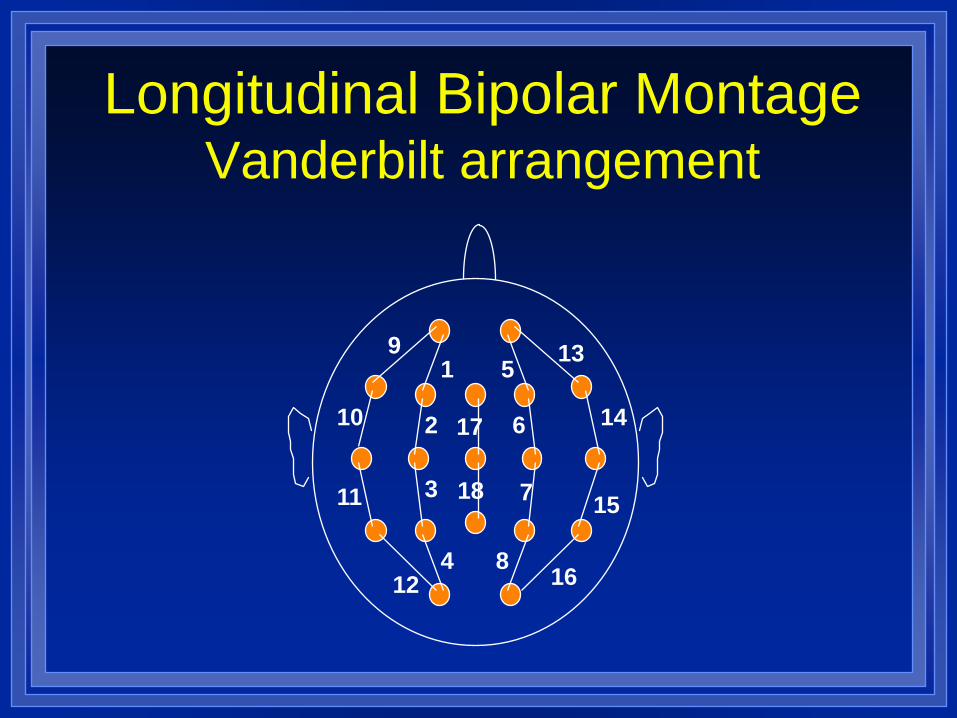
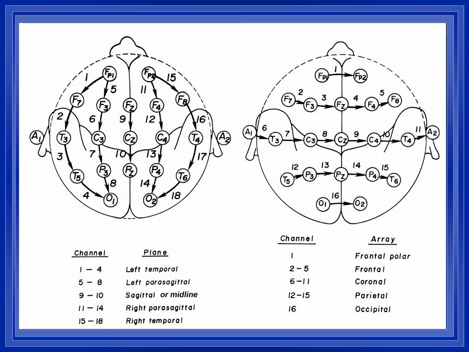
Longitudinal Bipolar Montage Vanderbilt arrangement
9
10
11
12
1
2
3
4
5
6
7
8
13
14
15
16
17
18
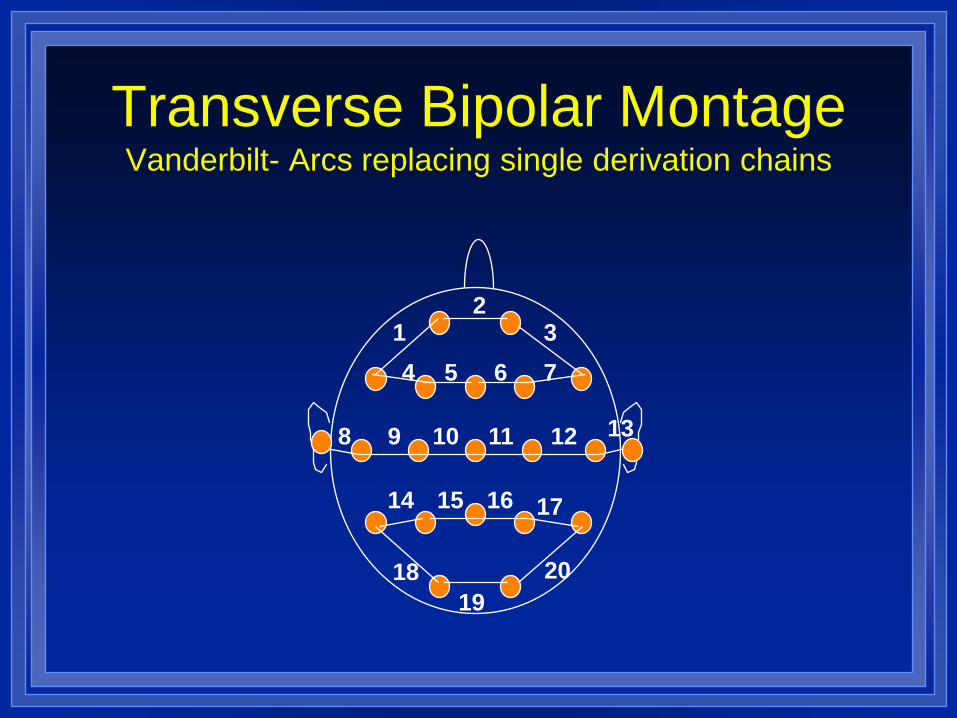
Transverse Bipolar Montage Vanderbilt- Arcs replacing single derivation chains
2
4 5 6 7
8 9 10 11 12 13
14 15 16 17
19
1 3
20 18
END OF CHAIN POTENTIALS
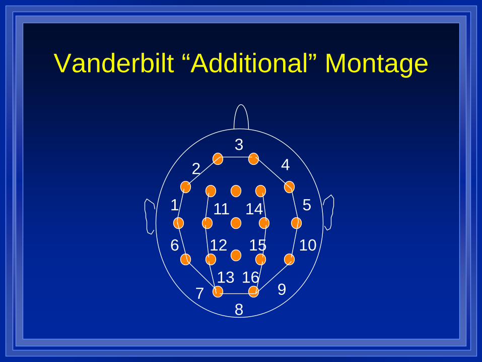
Vanderbilt “Additional” Montage
1
2 3
4
5
6
7 8
9
10
11
12
13
14
15
16
MONTAGES- REFERENTIAL
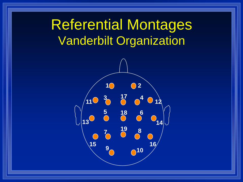
Referential Montages Vanderbilt Organization
1 2
3 4
5 6
7 8
9 10
11 12
13 14
15 16
17
18
19
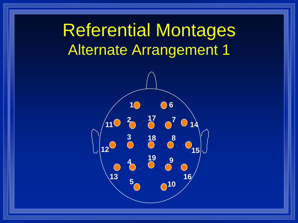
Referential Montages Alternate Arrangement 1
1 6
2 7
3 8
4 9
5 10
11 14
12 15
13 16
17
18
19
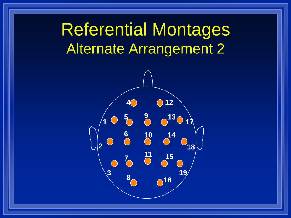
Referential Montages Alternate Arrangement 2
4 12
5 13
6 14
7 15
8 16
1 17
2 18
3 19
9
10
11
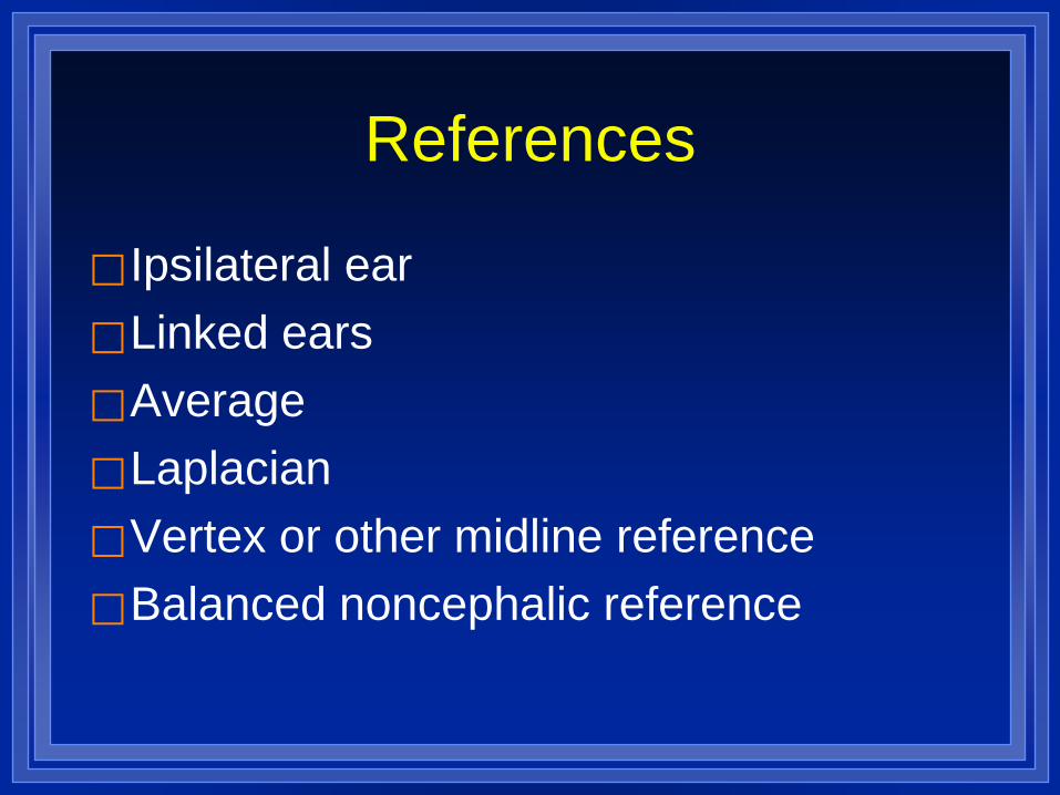
References
Ipsilateral ear Linked ears Average Laplacian Vertex or other midline reference Balanced noncephalic reference
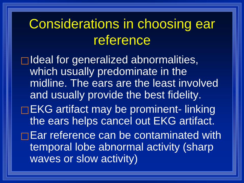
Considerations in choosing ear reference
Ideal for generalized abnormalities, which usually predominate in the midline. The ears are the least involved and usually provide the best fidelity.
EKG artifact may be prominent- linking the ears helps cancel out EKG artifact.
Ear reference can be contaminated with temporal lobe abnormal activity (sharp waves or slow activity)
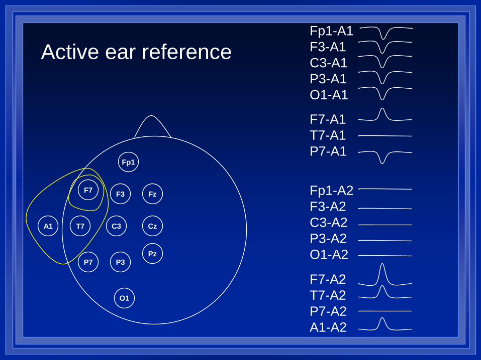
Fp1
F3
C3
F7
T7 A1
P3
O1
Cz
Pz
Fz
P7
Fp1-A1 F3-A1 C3-A1 P3-A1 O1-A1
F7-A1 T7-A1 P7-A1
Fp1-A2 F3-A2 C3-A2 P3-A2 O1-A2
F7-A2 T7-A2 P7-A2 A1-A2
Active ear reference
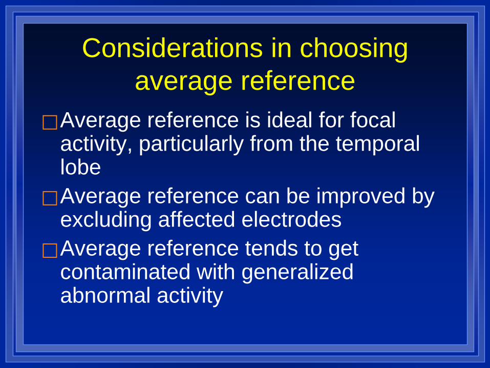
Considerations in choosing average reference
Average reference is ideal for focal activity, particularly from the temporal lobe
Average reference can be improved by excluding affected electrodes
Average reference tends to get contaminated with generalized abnormal activity
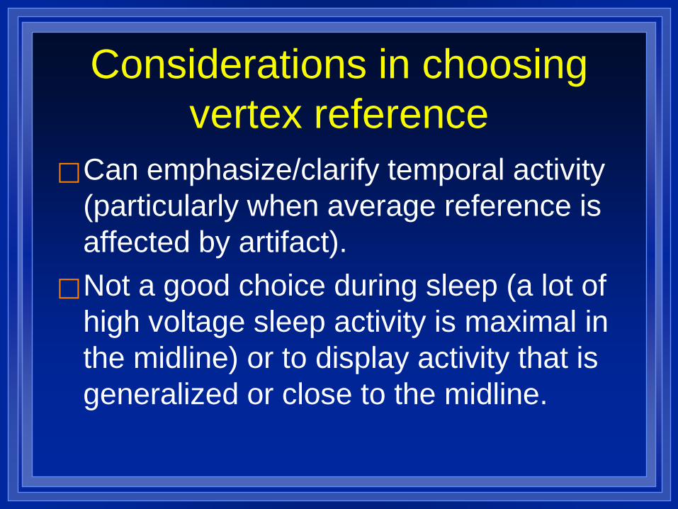
Considerations in choosing vertex reference
Can emphasize/clarify temporal activity (particularly when average reference is affected by artifact).
Not a good choice during sleep (a lot of high voltage sleep activity is maximal in the midline) or to display activity that is generalized or close to the midline.
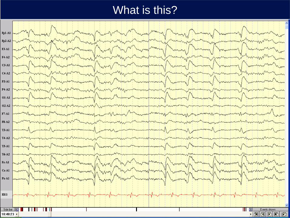
What is this?
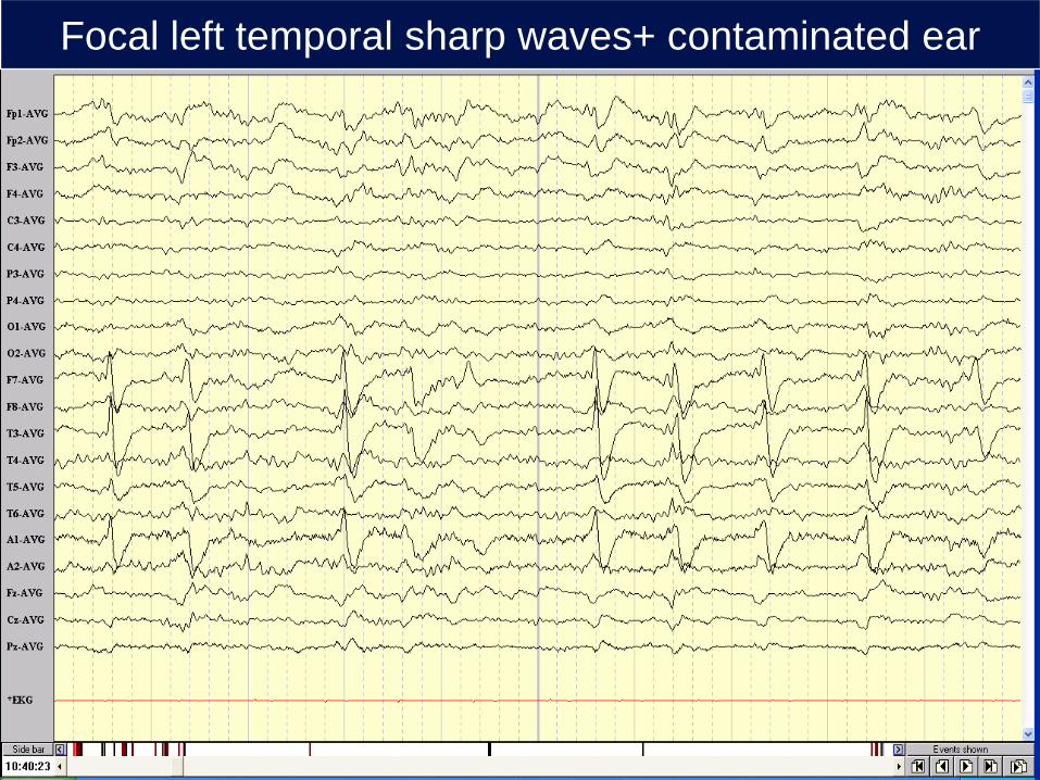
Focal left temporal sharp waves+ contaminated ear

Focal right temporal sharp waves- Average Ref
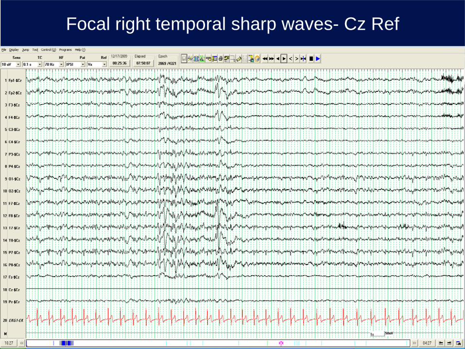
Focal right temporal sharp waves- Cz Ref
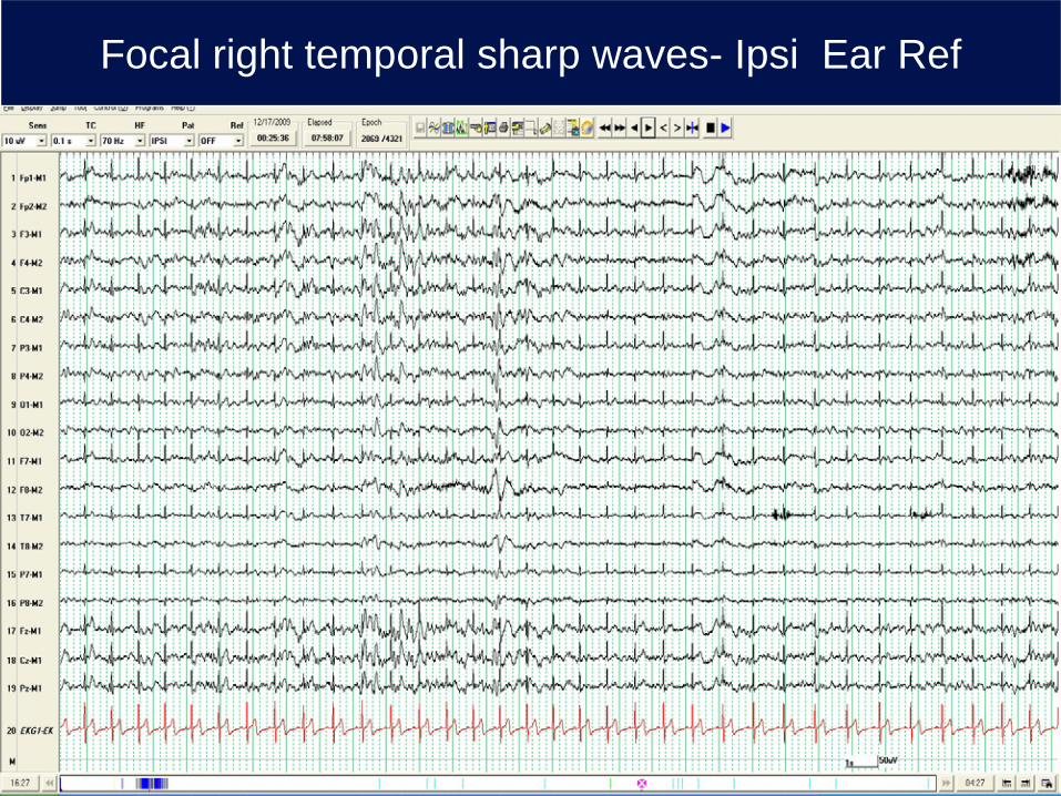
Focal right temporal sharp waves- Ipsi Ear Ref
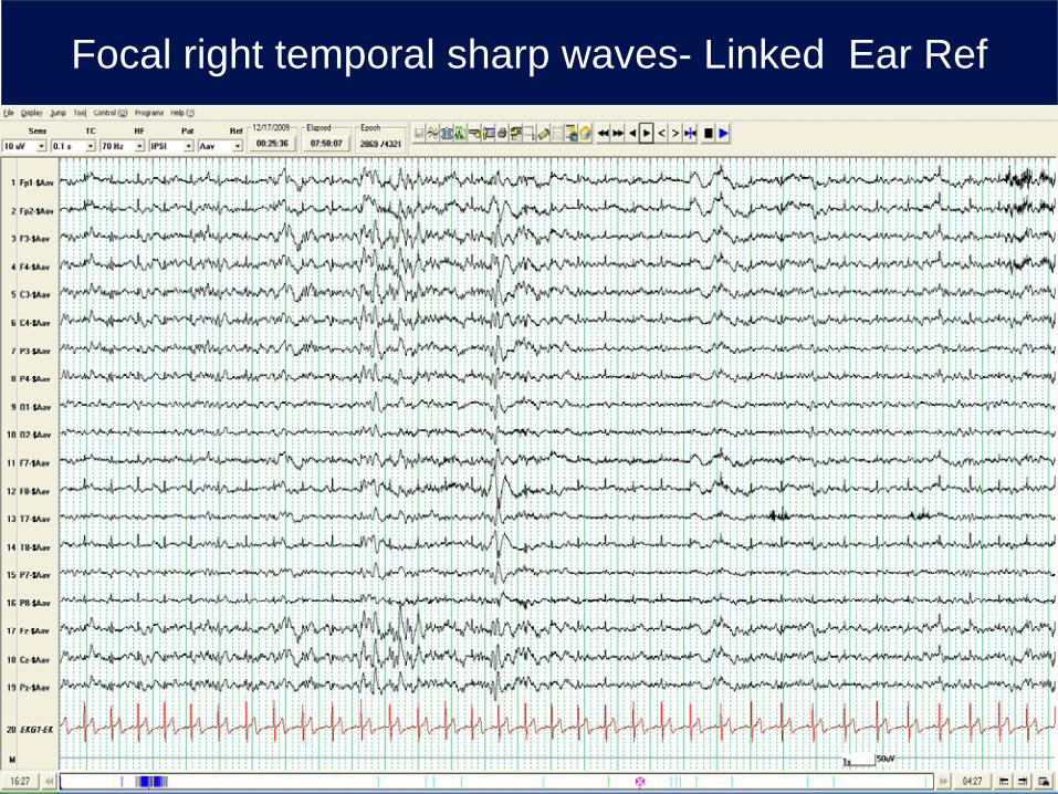
Focal right temporal sharp waves- Linked Ear Ref
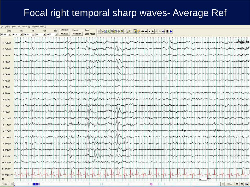
Focal right temporal sharp waves- Average Ref
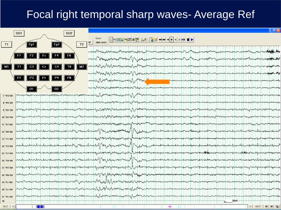
Average reference Focal right temporal sharp waves- Average Ref
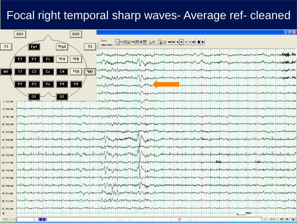
Average reference- ave cleaned Focal right temporal sharp waves- Average ref- cleaned
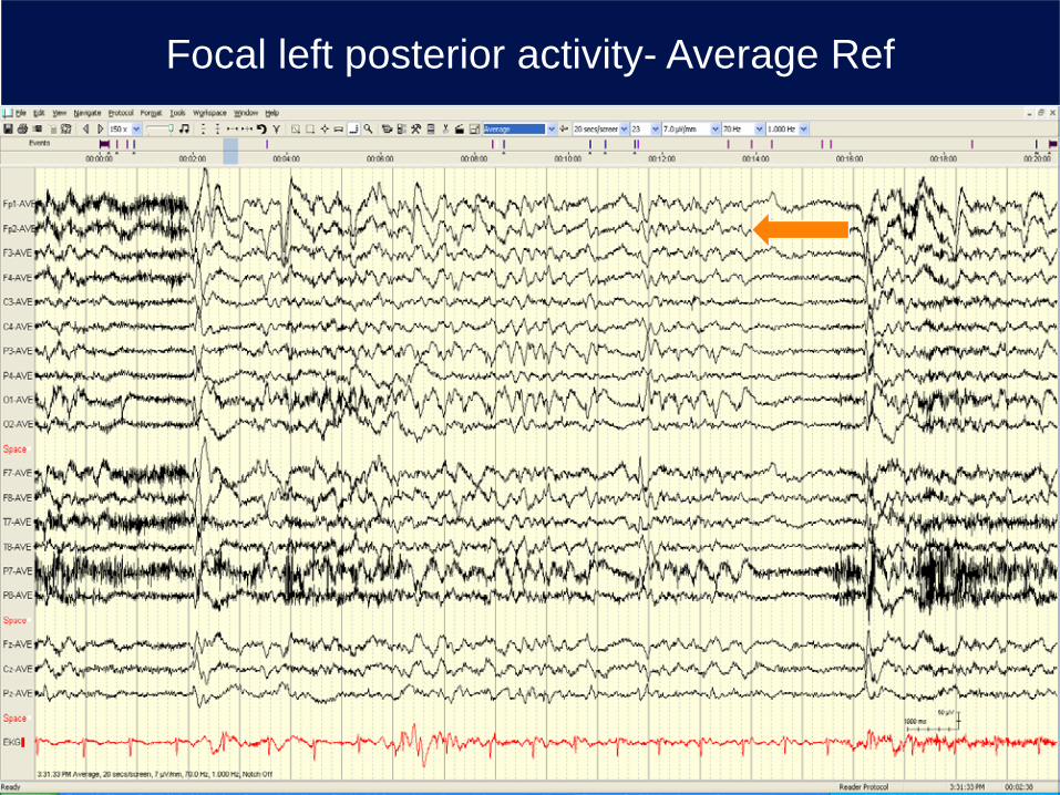
Focal left posterior activity- Average Ref
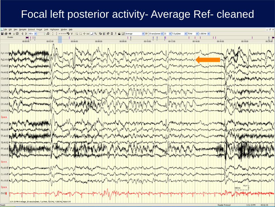
Focal left posterior activity- Average Ref- cleaned
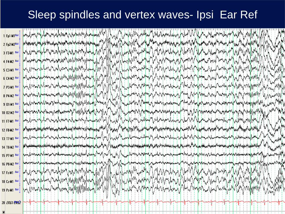
Sleep spindles and vertex waves- Ipsi Ear Ref
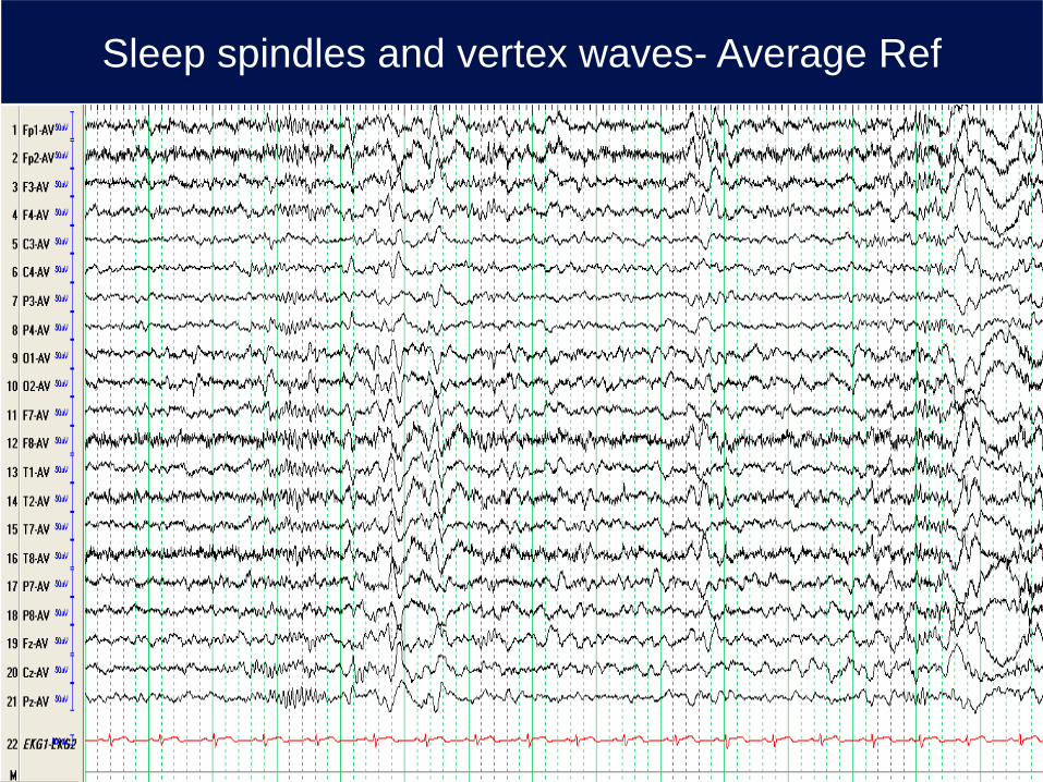
Sleep spindles and vertex waves- Average Ref
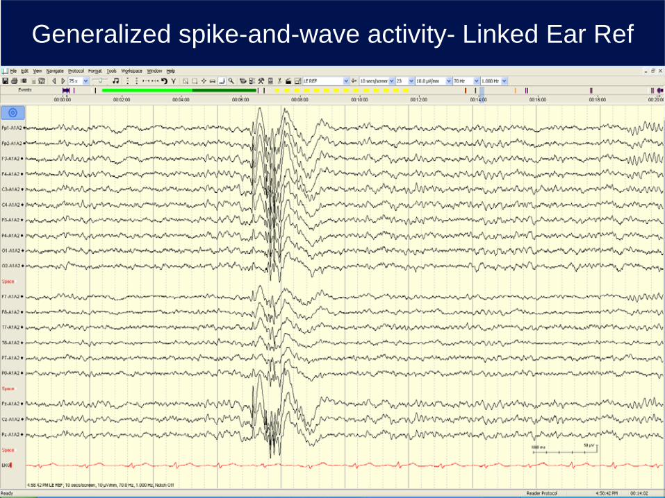
Generalized spike-and-wave activity- Linked Ear Ref
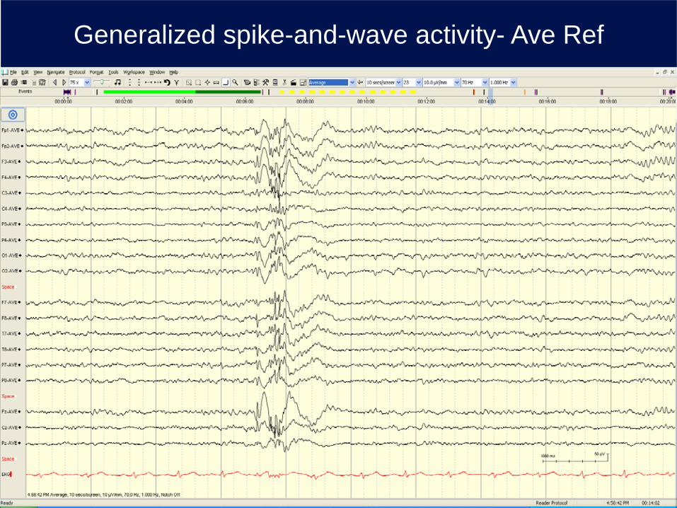
Generalized spike-and-wave activity- Ave Ref
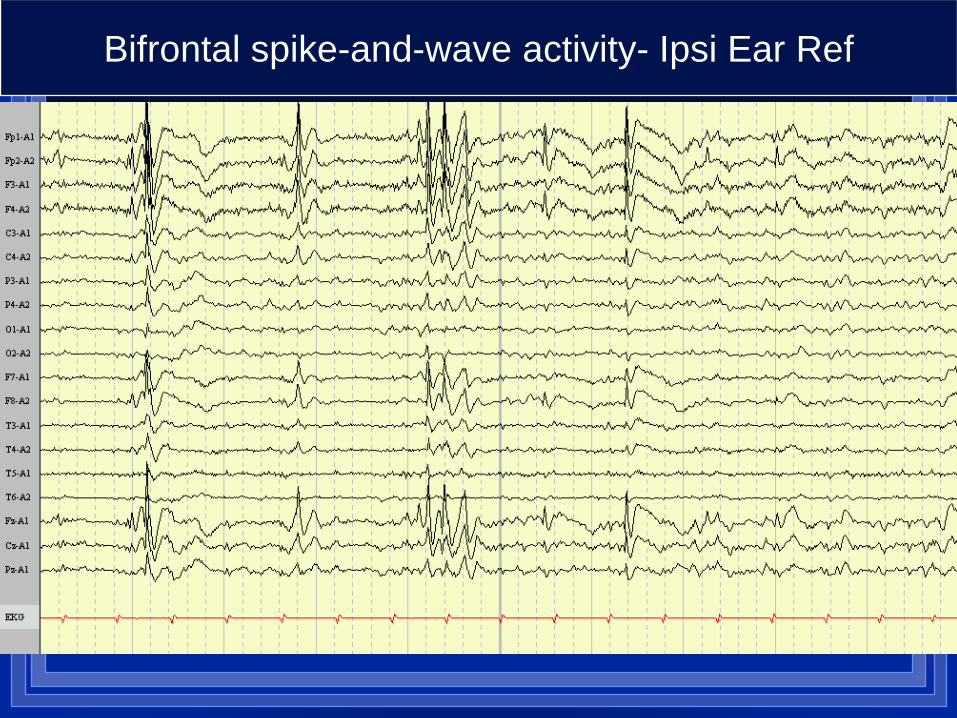
Bifrontal spike-and-wave activity- Ipsi Ear Ref
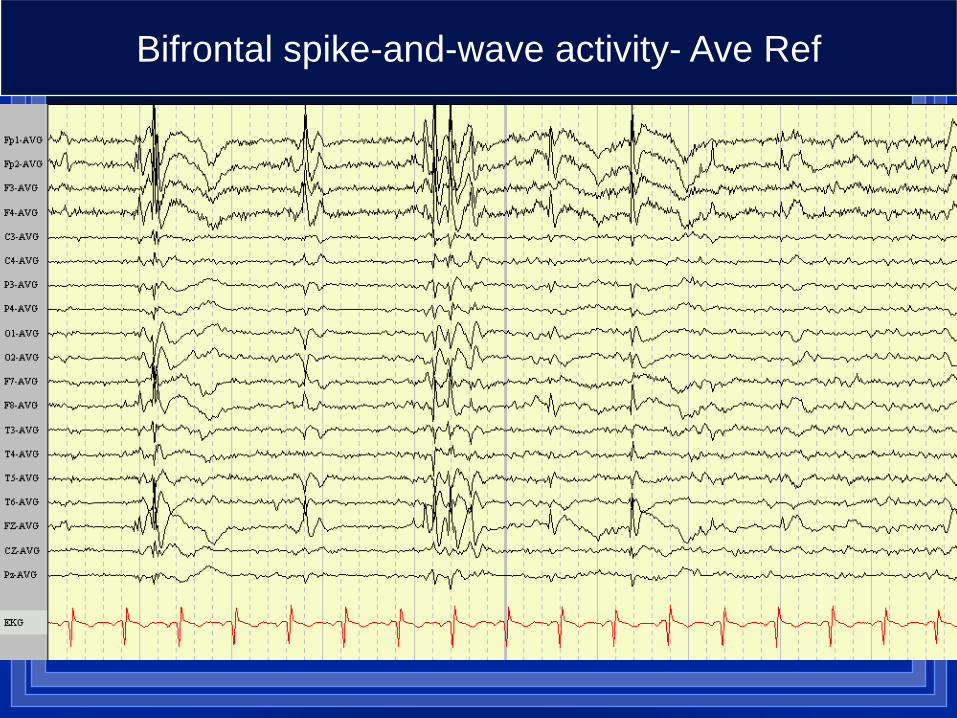
Bifrontal spike-and-wave activity- Ave Ref
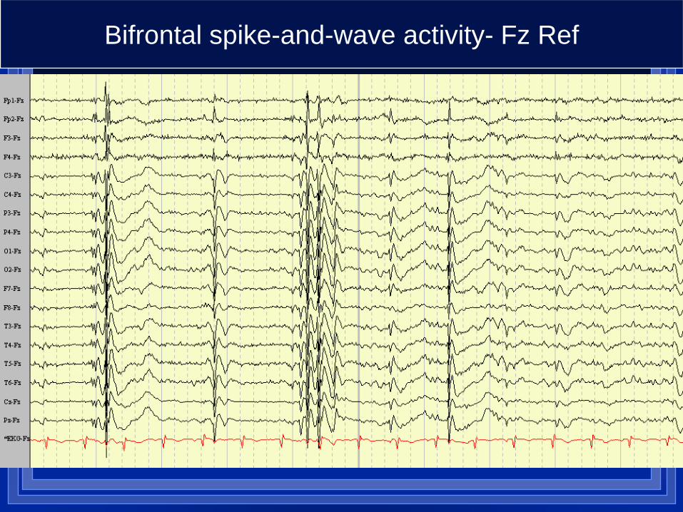
Bifrontal spike-and-wave activity- Fz Ref
Laplacian reference
Each channel in a Laplacian montage is referenced to an average of the electrodes surrounding it
Filters out coherent widespread activity and emphasizes localized waveforms
The Laplacian reference performs well in environments where low-to-moderate artifact can be expected (e.g., any in-lab or inpatient scalp EEG recording)
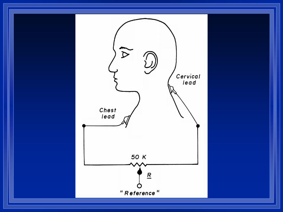
Balanced Non-Cephalic Reference
Can be considered when it is not possible to find a cephalic reference that is not contaminated by the EEG signal of interest.
Commonly used for evoked potential recordings, where signal averaging effectively removes EKG artifact.
EKG contamination is problematic, but can be diminished by deriving the reference from a combination of two electrodes. – If the electrodes are placed to present R-waves of
opposite polarity they can be summed to cancel each other, removing the EKG artifact from the non-cephalic reference.
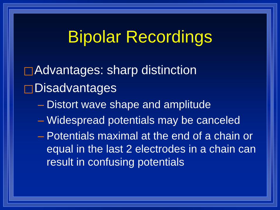
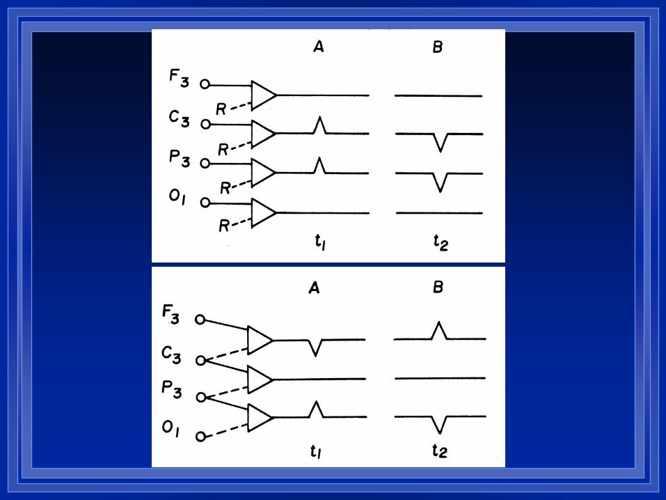
Bipolar Recordings
Advantages: sharp distinction Disadvantages
– Distort wave shape and amplitude – Widespread potentials may be canceled – Potentials maximal at the end of a chain or
equal in the last 2 electrodes in a chain can result in confusing potentials
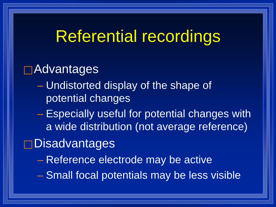
Referential recordings
Advantages – Undistorted display of the shape of
potential changes – Especially useful for potential changes with
a wide distribution (not average reference) Disadvantages
– Reference electrode may be active – Small focal potentials may be less visible
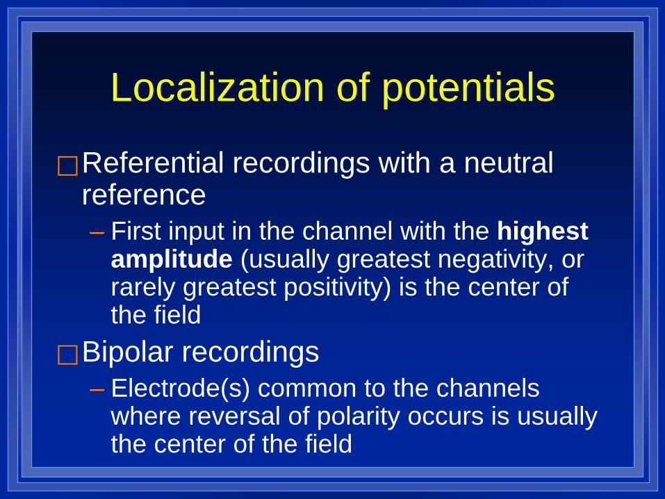
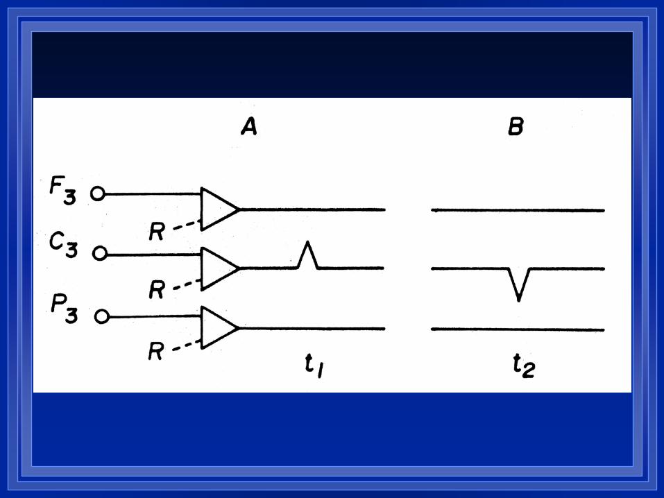
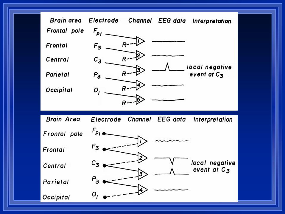
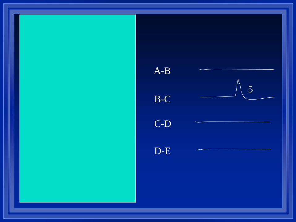
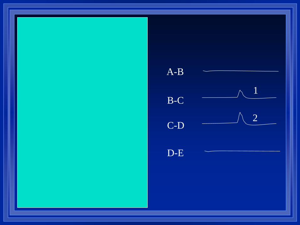
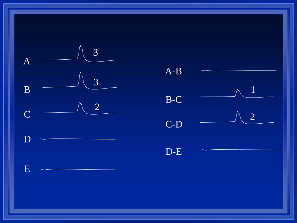
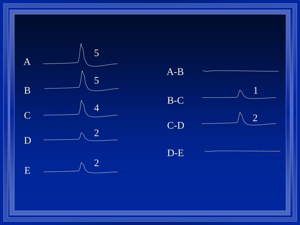
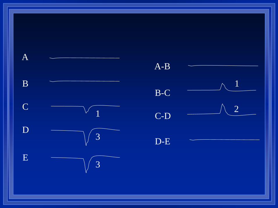
Localization of potentials
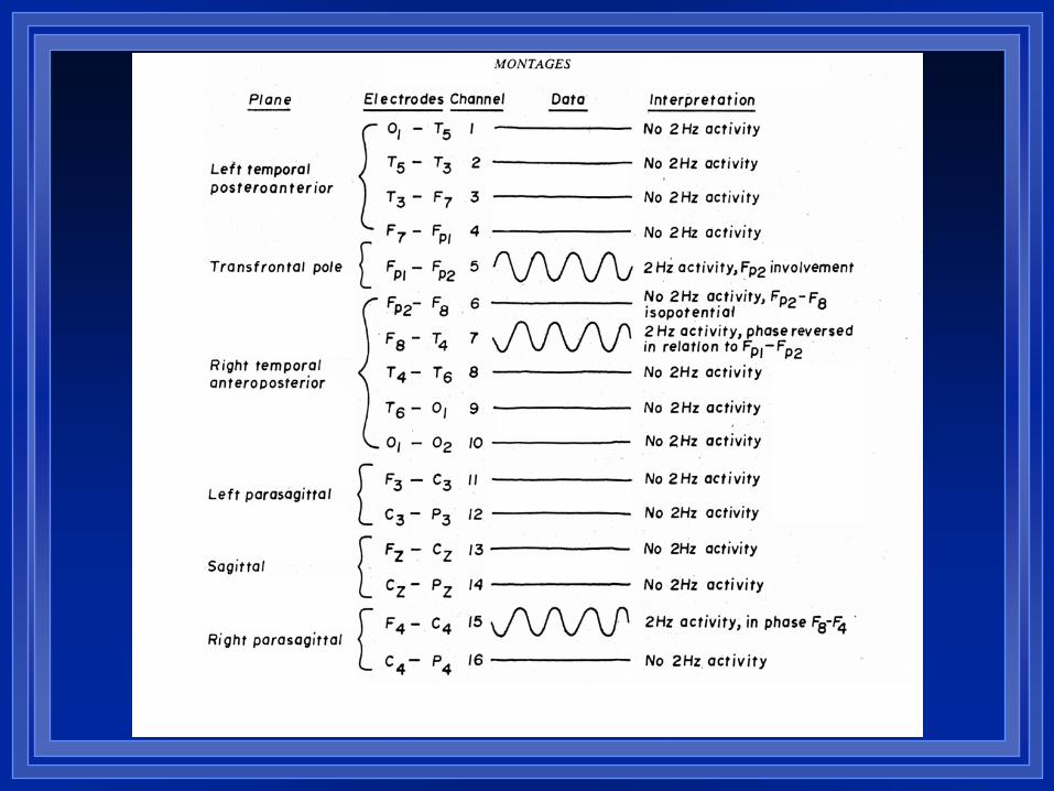
Referential recordings with a neutral reference – First input in the channel with the highest
amplitude (usually greatest negativity, or rarely greatest positivity) is the center of the field
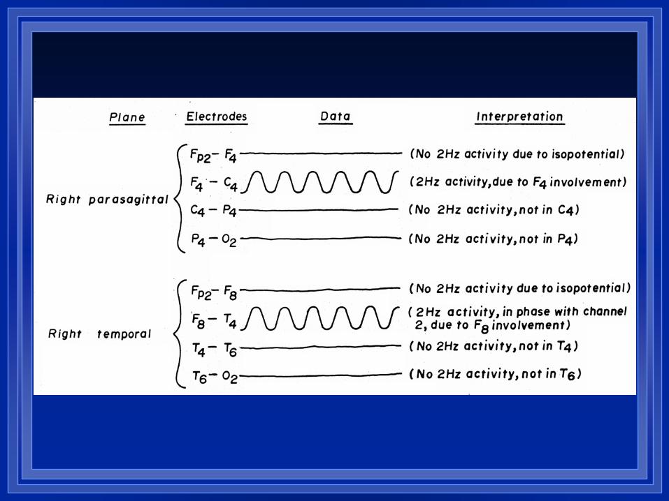
Bipolar recordings – Electrode(s) common to the channels
where reversal of polarity occurs is usually the center of the field
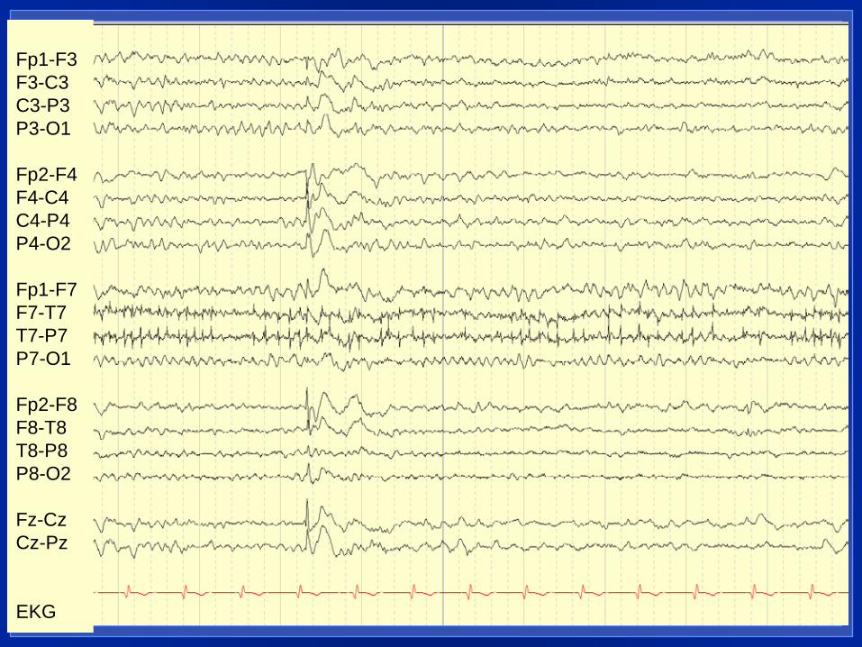
Fp1-F3 F3-C3 C3-P3 P3-O1 Fp2-F4 F4-C4 C4-P4 P4-O2 Fp1-F7 F7-T7 T7-P7 P7-O1 Fp2-F8 F8-T8 T8-P8 P8-O2 Fz-Cz Cz-Pz EKG
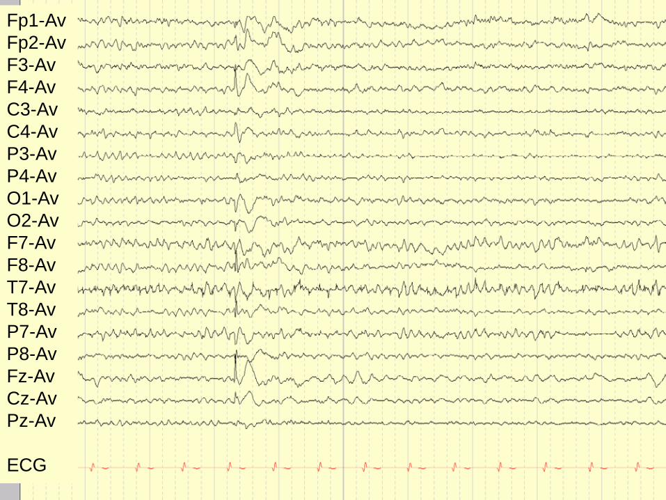
Fp1-Av Fp2-Av F3-Av F4-Av C3-Av C4-Av P3-Av P4-Av O1-Av O2-Av F7-Av F8-Av T7-Av T8-Av P7-Av P8-Av Fz-Av Cz-Av Pz-Av ECG
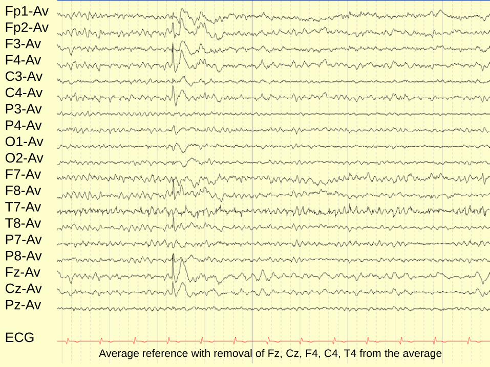
Fp1-Av Fp2-Av F3-Av F4-Av C3-Av C4-Av P3-Av P4-Av O1-Av O2-Av F7-Av F8-Av T7-Av T8-Av P7-Av P8-Av Fz-Av Cz-Av Pz-Av ECG Average reference with removal of Fz, Cz, F4, C4, T4 from the average
What is the polarity of the transient demonstrated below
A. Positive
B. Negative
C. Either positive or
negative
D. Neither
Fp1-F3

Where is the most likely source of this transient?
A. P3 and O1
B. O1
C. Fp1, C3, & P3
Fp1-F3
F3-C3
C3-P3
P3-O1

What is the most likely polarity of this transient?
A. Positive
B. Negative
C. Either positive
or negative
Fp1-F3
F3-C3
C3-P3
P3-O1
Where is the center of the field?
A. C3 and P3
B. C3
C. F3
D. Fp1
Fp1-F3
F3-C3
C3-P3
P3-O1
40 40
100
40
O1- X
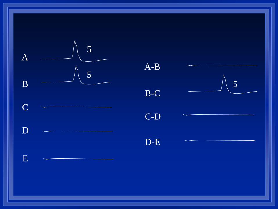
EEG LOCALIZATION PROBLEMS
Most likely solutions
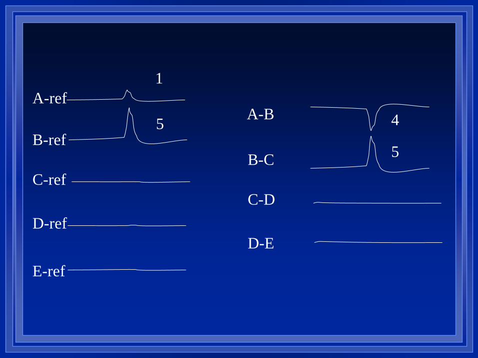
A-ref
B-ref
C-ref
D-ref
E-ref
A-B
B-C
C-D
D-E
1
5
5
4
A
B
C
D
E
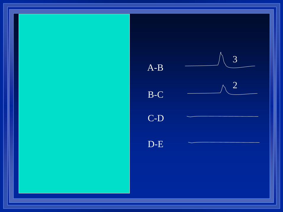
A-B
B-C
C-D
D-E
5
2
3
2
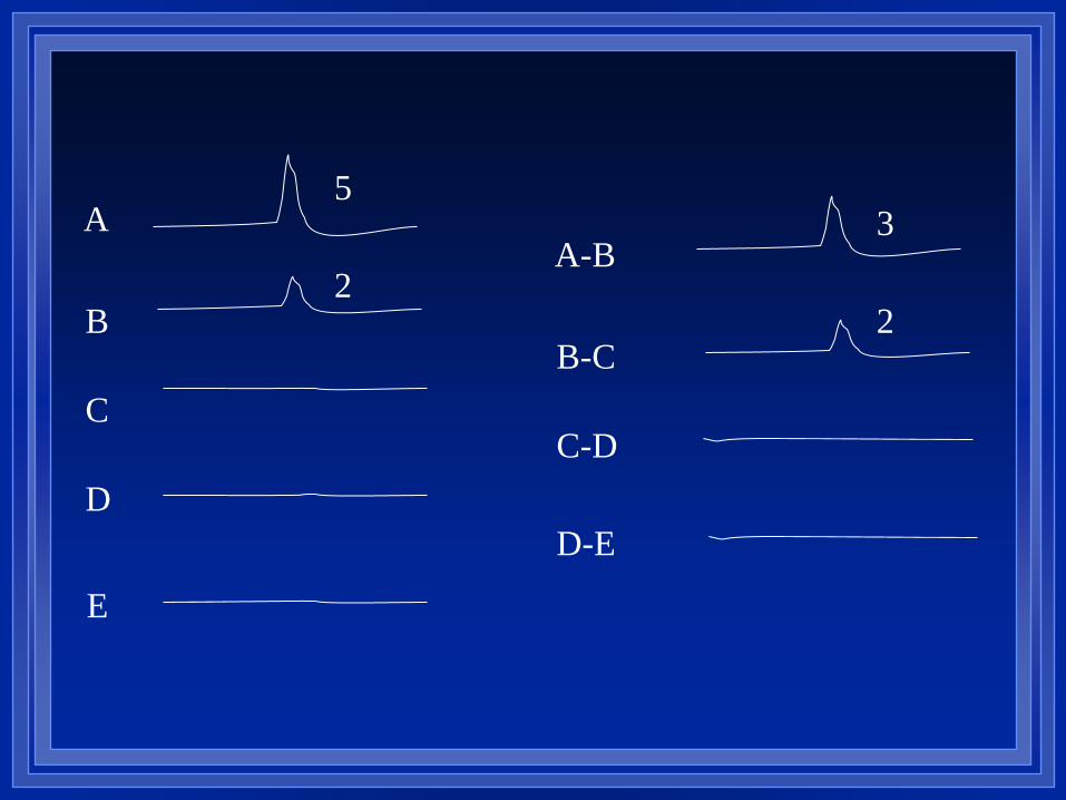
A
B
C
D
E
A-B
B-C
C-D
D-E
5
2
3
2
A
B
C
D
E
A-B
B-C
C-D
D-E
5
5 5
A
B
C
D
E
A-B
B-C
C-D
D-E
5
5 5
A
B
C
D
E
A-B
B-C
C-D
D-E
5
5
5
5
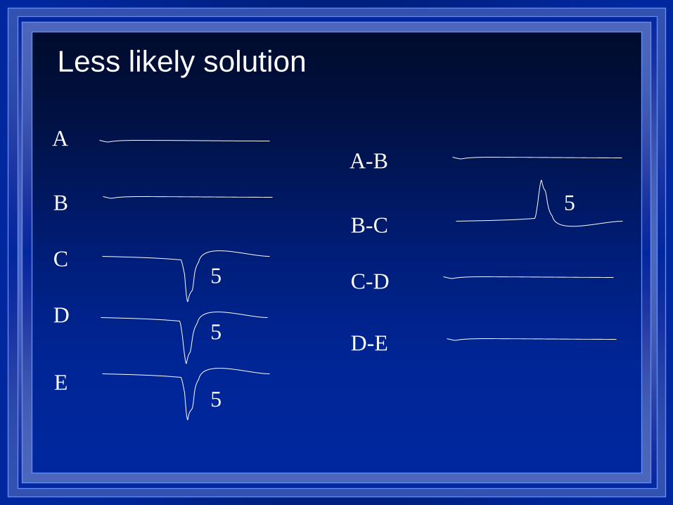
Less likely solution
A
B
C
D
E
5
5
4
2
2
A-B
B-C
C-D
D-E
2
1
A
B
C
D
E
3
A-B
B-C
C-D
D-E
2
1 3
2
A
B
C
D
E
5
5
4
2
2
A-B
B-C
C-D
D-E
2
1
A
B
C
D
E
A-B
B-C
C-D
D-E
2
1
1
3
3

![Montages - cvillecameraclub.orgcvillecameraclub.org/sites/default/files/Montages... · Montages: Interpreting Reality by Matthew G. Schmidt. Montage [mɒnˈtɑːʒ (French) mɔ̃taʒ]](https://img.pdfslide.us/doc/110x75/5f3b21e0bdc6647f560a123b/montages-montages-interpreting-reality-by-matthew-g-schmidt-montage-mnt.jpg)