Embed Size (px)
Citation preview
I
NS
TALL
AT
ION
& O
WN
ER
’S M
AN
UA
L p. 1 of 13
The contents of this envelope are the property of the owner. Be sure to leave with the owner when installation is complete.
Polaris Ranger 400-EV PathPro SS Cab (fits 2010 - current)
(p/n: 1PRG400FS)
APPROXIMATE INSTALLATION TIME: 3 HOURS (excluding accessories)
Rev. C, 7/6/2017 p/n: IM-1PRG400FS
Shown with optional Windshield Wiper (p/n: 1POLRLCWPR)
Additional options available (not shown): Interior Rear View Mirror (p/n: 9PM3)
Work lights (p/n: 9LW1) Heater (p/n: 9PH20S42) Strobe Light (p/n: 9LS1)
GENERAL INFORMATION BEFORE YOU START HELPFUL HINTS: A. Refer to parts diagram toward the back of this manual to help identify
parts during the assembly process. B. To assist with the cab installation, leave all bolts loose for later adjust-
ment unless otherwise specified. C. Read and understand all instructions before beginning. D. Plastic washers have been supplied to provide a weather seal under
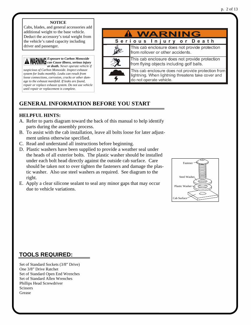
the heads of all exterior bolts. The plastic washer should be installed under each bolt head directly against the outside cab surface. Care should be taken not to over tighten the fasteners and damage the plas-tic washer. Also use steel washers as required. See diagram to the right.
E. Apply a clear silicone sealant to seal any minor gaps that may occur due to vehicle variations.
TOOLS REQUIRED:
p. 2 of 13
Fastener
Cab Surface
Steel Washer
Plastic Washer
Set of Standard Sockets (3/8” Drive) One 3/8” Drive Ratchet Set of Standard Open End Wrenches Set of Standard Allen Wrenches Phillips Head Screwdriver Scissors Grease
NOTICE Cabs, blades, and general accessories add additional weight to the base vehicle. Deduct the accessory’s total weight from the vehicle’s rated capacity including driver and passenger.
Exposure to Carbon Monoxide can Cause illness, serious injury or death. Never operate vehicle if
suspicious of Carbon Monoxide. Inspect exhaust system for leaks monthly. Leaks can result from loose connections, corrosion, cracks or other dam-age to the exhaust manifold. If leaks are found, repair or replace exhaust system. Do not use vehicle until repair or replacement is complete.
p. 3 of 13
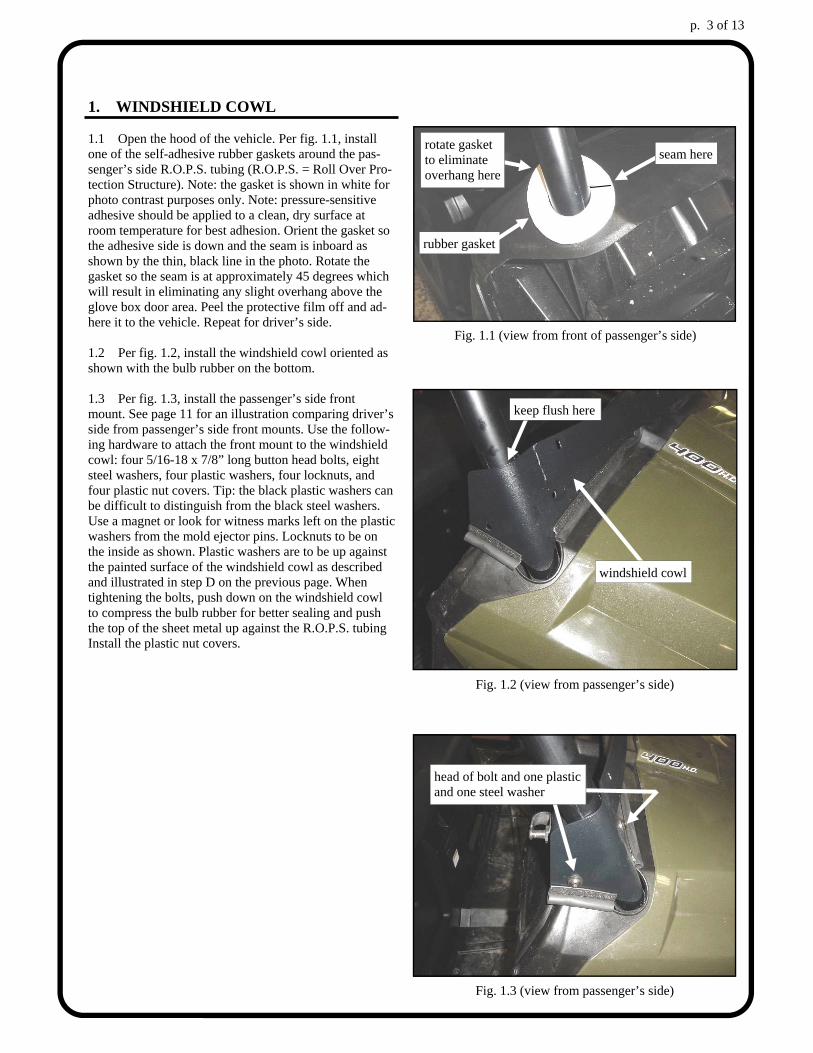
1. WINDSHIELD COWL 1.1 Open the hood of the vehicle. Per fig. 1.1, install one of the self-adhesive rubber gaskets around the pas-senger’s side R.O.P.S. tubing (R.O.P.S. = Roll Over Pro-tection Structure). Note: the gasket is shown in white for photo contrast purposes only. Note: pressure-sensitive adhesive should be applied to a clean, dry surface at room temperature for best adhesion. Orient the gasket so the adhesive side is down and the seam is inboard as shown by the thin, black line in the photo. Rotate the gasket so the seam is at approximately 45 degrees which will result in eliminating any slight overhang above the glove box door area. Peel the protective film off and ad-here it to the vehicle. Repeat for driver’s side. 1.2 Per fig. 1.2, install the windshield cowl oriented as shown with the bulb rubber on the bottom. 1.3 Per fig. 1.3, install the passenger’s side front mount. See page 11 for an illustration comparing driver’s side from passenger’s side front mounts. Use the follow-ing hardware to attach the front mount to the windshield cowl: four 5/16-18 x 7/8” long button head bolts, eight steel washers, four plastic washers, four locknuts, and four plastic nut covers. Tip: the black plastic washers can be difficult to distinguish from the black steel washers. Use a magnet or look for witness marks left on the plastic washers from the mold ejector pins. Locknuts to be on the inside as shown. Plastic washers are to be up against the painted surface of the windshield cowl as described and illustrated in step D on the previous page. When tightening the bolts, push down on the windshield cowl to compress the bulb rubber for better sealing and push the top of the sheet metal up against the R.O.P.S. tubing Install the plastic nut covers.
Fig. 1.3 (view from passenger’s side)
head of bolt and one plastic and one steel washer
Fig. 1.1 (view from front of passenger’s side)
rotate gasket to eliminate overhang here
seam here
Fig. 1.2 (view from passenger’s side)
windshield cowl
keep flush here
rubber gasket
p. 4 of 13
2. ROOF 2.1 With assistance, place the roof (headliner side up) on a cloth protected work bench or floor to prevent scratches during the following pre-assembly steps. Use a Phillips head screwdriver to punch a hole through the headliner at any of the covered bolt hole locations (12 places). Punch holes from the inside out to avoid having the headliner pull away from its glued surface. 2.2 For orientation purposes, the front corner of the roof has the 1-3/4” high side as shown in fig. 2.2. Loosely assemble the windshield support to the roof using five 5/16-18 x 7/8” long button head bolts, five plastic washers, ten 5/16” small, standard, steel wash-ers, and five locknuts. The nuts should just be finger tight at this time. 2.3 Per fig. 2.3, loosely assemble the rear panel sup-port to the roof using five 5/16-18 x 7/8” long button head bolts, five plastic washers, ten 5/16” small, stand-ard, steel washers, and five locknuts. The nuts should just be finger tight at this time. 2.4 Per fig. 2.4, install the bolt for the door stop cable (one per side of roof) as shown. Use the following hard-ware per side: one 5/16-18 x 1 1/4” long button head bolt, two steel washers, one plastic washer, and two locknuts. With the roof still oriented as shown (with the headliner up), install one steel washer and one plastic washer on to the bolt. Feed the bolt up from the bottom side, through the sheet metal and through the foam headliner. Install the second steel washer and one lock-nut. Tighten the locknut (locknut #1 in figure 2.4). In-stall one end of the door stop cable onto the bolt. Install the second locknut, but do not tighten it up against the door stop cable. There should be a small intentional gap so the cable can rotate freely. Repeat in the last remain-ing roof hole.
Fig. 2.2 (installation order)
Fastener
Cab Surface
Steel Washer
Plastic Washer
Fig. 2.2 (view of windshield support on top of headliner)
windshield support
ref.: front corner of roof
Fig. 2.3 (view of rear roof support on top of headliner)
rear roof support
ref.: rear corner of roof
Fig. 2.4 (view of door stop cable bolt)
locknut #2
ref.: headliner
locknut #1
install the door stop cable bet- ween the locknuts
p. 5 of 13
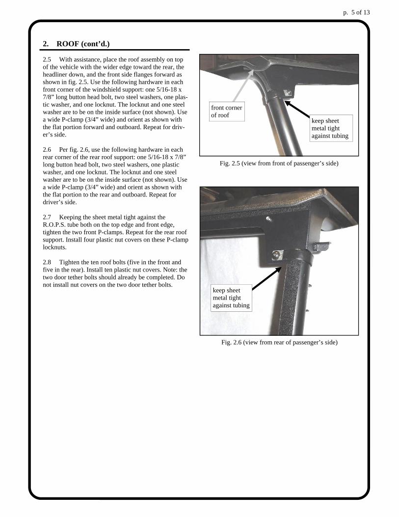
2. ROOF (cont’d.) 2.5 With assistance, place the roof assembly on top of the vehicle with the wider edge toward the rear, the headliner down, and the front side flanges forward as shown in fig. 2.5. Use the following hardware in each front corner of the windshield support: one 5/16-18 x 7/8” long button head bolt, two steel washers, one plas-tic washer, and one locknut. The locknut and one steel washer are to be on the inside surface (not shown). Use a wide P-clamp (3/4” wide) and orient as shown with the flat portion forward and outboard. Repeat for driv-er’s side. 2.6 Per fig. 2.6, use the following hardware in each rear corner of the rear roof support: one 5/16-18 x 7/8” long button head bolt, two steel washers, one plastic washer, and one locknut. The locknut and one steel washer are to be on the inside surface (not shown). Use a wide P-clamp (3/4” wide) and orient as shown with the flat portion to the rear and outboard. Repeat for driver’s side. 2.7 Keeping the sheet metal tight against the R.O.P.S. tube both on the top edge and front edge, tighten the two front P-clamps. Repeat for the rear roof support. Install four plastic nut covers on these P-clamp locknuts. 2.8 Tighten the ten roof bolts (five in the front and five in the rear). Install ten plastic nut covers. Note: the two door tether bolts should already be completed. Do not install nut covers on the two door tether bolts.
Fig. 2.5 (view from front of passenger’s side)
keep sheet metal tight against tubing
Fig. 2.6 (view from rear of passenger’s side)
keep sheet metal tight against tubing
front corner of roof
p. 6 of 13
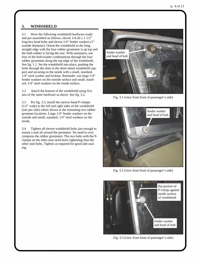
3. WINDSHIELD 3.1 Have the following windshield hardware ready and pre-assembled as follows: eleven 1/4-20 x 1 1/2” long hex head bolts and eleven 1/4” fender washers (1” outside diameter). Orient the windshield so the long, straight edge with the four rubber grommets is up top and the bulb rubber is facing the rear. With assistance, use four of the bolt/washer combinations through the four rubber grommets along the top edge of the windshield. See fig. 1.1. Set the windshield into place, pushing the bolts through the slots in the sheet metal windshield sup-port and securing on the inside with a small, standard, 1/4” steel washer and locknut. Reminder: use large 1/4” fender washers on the outside surface and small, stand-ard, 1/4” steel washers on the inside surface. 3.2 Attach the bottom of the windshield using five sets of the same hardware as above. See fig. 3.2. 3.3 Per fig. 3.3, install the narrow band P-clamps (1/2” wide) to the left and right sides of the windshield (one per side) where shown at the remaining two rubber grommet locations. Large 1/4” fender washers on the outside and small, standard, 1/4” steel washers on the inside. 3.4 Tighten all eleven windshield bolts just enough to ensure a seal all around the perimeter. No need to over compress the rubber grommets. The two bolts with the P-clamps on the sides may need more tightening than the other nine bolts. Tighten as required for good side seal-ing.
Fig. 3.1 (view from front of passenger’s side)
fender washer and head of bolt
Fig. 3.2 (view from front of passenger’s side)
fender washer and head of bolt
Fig. 3.3 (view from front of passenger’s side)
fender washer and head of bolt
flat portion of P-clamp against inside surface of windshield
p. 7 of 13
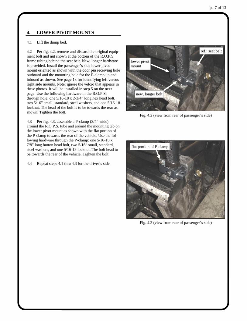
4. LOWER PIVOT MOUNTS 4.1 Lift the dump bed. 4.2 Per fig. 4.2, remove and discard the original equip-ment bolt and nut shown at the bottom of the R.O.P.S. frame tubing behind the seat belt. New, longer hardware is provided. Install the passenger’s side lower pivot mount oriented as shown with the door pin receiving hole outboard and the mounting hole for the P-clamp up and inboard as shown. See page 13 for identifying left versus right side mounts. Note: ignore the velcro that appears in these photos. It will be installed in step 5 on the next page. Use the following hardware in the R.O.P.S. through hole: one 5/16-18 x 2-3/4” long hex head bolt, two 5/16” small, standard, steel washers, and one 5/16-18 locknut. The head of the bolt is to be towards the rear as shown. Tighten the bolt. 4.3 Per fig. 4.3, assemble a P-clamp (3/4” wide) around the R.O.P.S. tube and around the mounting tab on the lower pivot mount as shown with the flat portion of the P-clamp towards the rear of the vehicle. Use the fol-lowing hardware through the P-clamp: one 5/16-18 x 7/8” long button head bolt, two 5/16” small, standard, steel washers, and one 5/16-18 locknut. The bolt head to be towards the rear of the vehicle. Tighten the bolt. 4.4 Repeat steps 4.1 thru 4.3 for the driver’s side.
Fig. 4.2 (view from rear of passenger’s side)
new, longer bolt
Fig. 4.3 (view from rear of passenger’s side)
ref.: seat belt
lower pivot mount
flat portion of P-clamp
p. 8 of 13
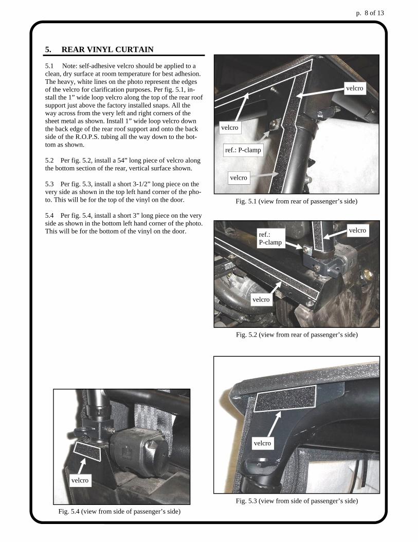
5. REAR VINYL CURTAIN 5.1 Note: self-adhesive velcro should be applied to a clean, dry surface at room temperature for best adhesion. The heavy, white lines on the photo represent the edges of the velcro for clarification purposes. Per fig. 5.1, in-stall the 1” wide loop velcro along the top of the rear roof support just above the factory installed snaps. All the way across from the very left and right corners of the sheet metal as shown. Install 1” wide loop velcro down the back edge of the rear roof support and onto the back side of the R.O.P.S. tubing all the way down to the bot-tom as shown. 5.2 Per fig. 5.2, install a 54” long piece of velcro along the bottom section of the rear, vertical surface shown. 5.3 Per fig. 5.3, install a short 3-1/2” long piece on the very side as shown in the top left hand corner of the pho-to. This will be for the top of the vinyl on the door. 5.4 Per fig. 5.4, install a short 3” long piece on the very side as shown in the bottom left hand corner of the photo. This will be for the bottom of the vinyl on the door.
Fig. 5.1 (view from rear of passenger’s side)
ref.: P-clamp
velcro
velcro
velcro
Fig. 5.2 (view from rear of passenger’s side)
ref.: P-clamp
velcro
velcro
Fig. 5.3 (view from side of passenger’s side)
velcro
Fig. 5.4 (view from side of passenger’s side)
velcro
p. 9 of 13
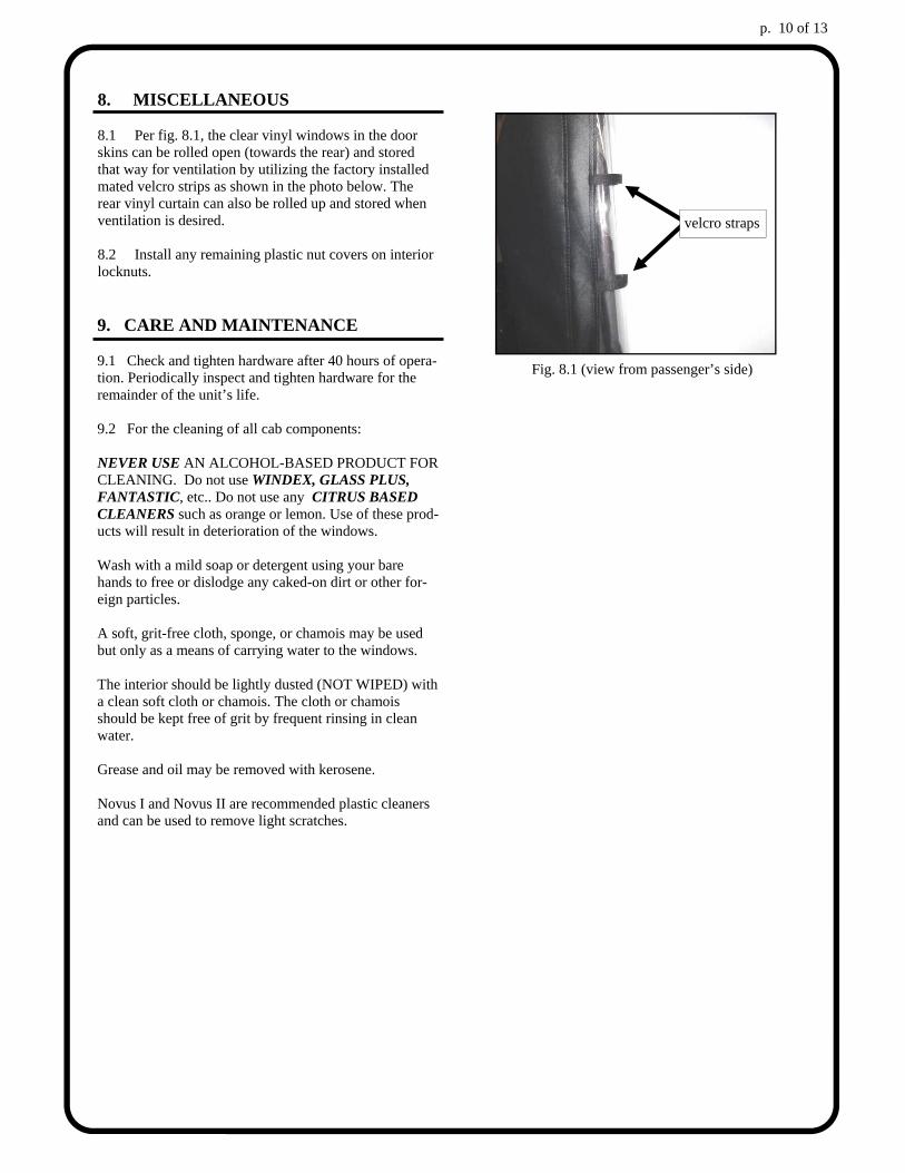
6. DOORS 6.1 Prior to installing the doors, apply grease or other lubricant to the bottom side of the washers welded on to the door pin or to the top surface of the tabs with the re-ceiving holes where indicated in fig. 6.1. 6.2 Per fig. 6.1, engage the two door pins (hinges) into their respective receiving holes. 6.3 If necessary, adjust the latch on the door front to back and/or the pin on the front mount up and down until a “double click” is achieved. Continue to adjust the en-gagement as necessary until you get the door to close with “two” clicks which is confirmation that the door is fully closed and secure enough to drive. 6.4 Per fig. 6.1, the loose vinyl door flap can now be attached to the mating velcro on the back side of the rear vinyl curtain.
Condition: Explanation/Solution
Door latch and striker pin does not line up (up and down) Move striker pin on front mount up or down. Rotate lower pivot mount forward or back.
Door latch and striker pin does not line up (front to back) Move latch on door forwards or backwards.
Troubleshooting the door Fig. 6.1 (view from side of passenger’s side)
door pin thru hole
lubricate here
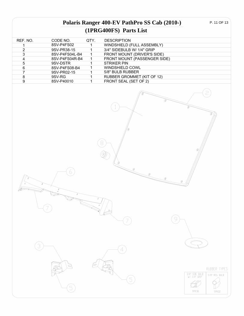
7. DOOR TETHER 7.1 Per fig. 7.1, connect the free end of the door stop cable to the door. Leave it slightly loose so that the cable may rotate freely.
Fig. 7.1 (view of passenger’s door from inside the cab)
door stop cable
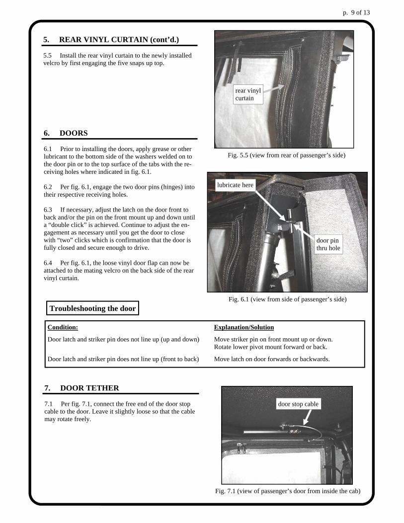
5. REAR VINYL CURTAIN (cont’d.) 5.5 Install the rear vinyl curtain to the newly installed velcro by first engaging the five snaps up top.
Fig. 5.5 (view from rear of passenger’s side)
rear vinyl curtain
p. 10 of 13
9. CARE AND MAINTENANCE
9.1 Check and tighten hardware after 40 hours of opera-tion. Periodically inspect and tighten hardware for the remainder of the unit’s life. 9.2 For the cleaning of all cab components: NEVER USE AN ALCOHOL-BASED PRODUCT FOR CLEANING. Do not use WINDEX, GLASS PLUS, FANTASTIC, etc.. Do not use any CITRUS BASED CLEANERS such as orange or lemon. Use of these prod-ucts will result in deterioration of the windows. Wash with a mild soap or detergent using your bare hands to free or dislodge any caked-on dirt or other for-eign particles. A soft, grit-free cloth, sponge, or chamois may be used but only as a means of carrying water to the windows. The interior should be lightly dusted (NOT WIPED) with a clean soft cloth or chamois. The cloth or chamois should be kept free of grit by frequent rinsing in clean water. Grease and oil may be removed with kerosene. Novus I and Novus II are recommended plastic cleaners and can be used to remove light scratches.
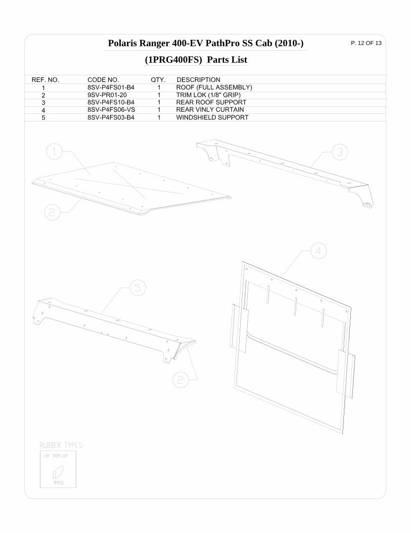
Fig. 8.1 (view from passenger’s side)
velcro straps
8. MISCELLANEOUS 8.1 Per fig. 8.1, the clear vinyl windows in the door skins can be rolled open (towards the rear) and stored that way for ventilation by utilizing the factory installed mated velcro strips as shown in the photo below. The rear vinyl curtain can also be rolled up and stored when ventilation is desired. 8.2 Install any remaining plastic nut covers on interior locknuts.
Polaris Ranger 400-EV PathPro SS Cab (2010-) P. 11 OF 13
(1PRG400FS) Parts List
P. 12 OF 13Polaris Ranger 400-EV PathPro SS Cab (2010-)
(1PRG400FS) Parts List
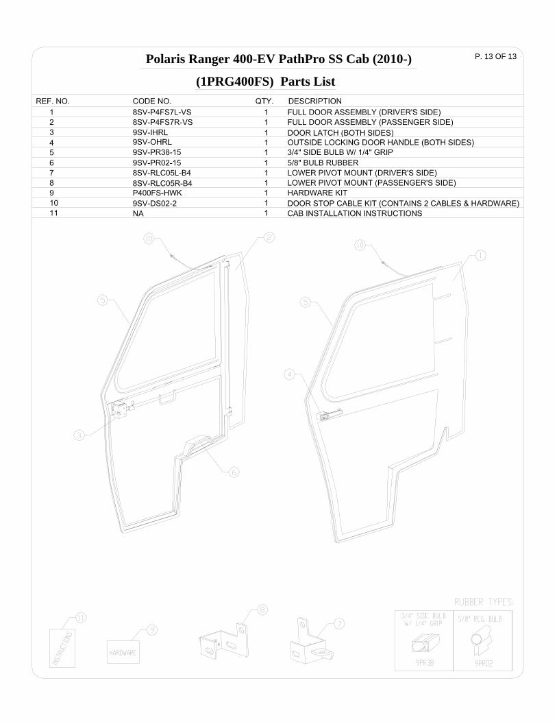
P. 13 OF 13
(1PRG400FS) Parts List
Polaris Ranger 400-EV PathPro SS Cab (2010-)


![GUTSY TEXTURED COWL | CROCHET - Amazon S3...Say goodbye to crocheter's block GUTSY TEXTURES COWL | CROCHET 1 of 1GUTSY TEXTURED COWL | CROCHETMEASUREMENTS Approx 14" [35.5 cm] deep](https://img.pdfslide.us/doc/110x75/5f8a3d4788656b1f68681f45/gutsy-textured-cowl-crochet-amazon-s3-say-goodbye-to-crocheters-block-gutsy.jpg)