Embed Size (px)
Citation preview
BoonDocker Liquid Nitrous – 1589 Hollipark Dr. Idaho Falls, ID 83401 – (208) 542-4411 website: www.boondockers.com - email: [email protected]
Revised 01-21-05 Page 1 of 11
1
BoonDocker Nitrous System Installation Instructions for Polaris 900 EFI Snowmobile
Important information. REGISTER THIS PRODUCT ONLINE AS SOON AS POSSIBLE As part of our on going dedication to customer satisfaction, product updates may become available for the Control Box as more testing and development is completed. It is required that you register this product so you can receive technical support and warranty claims. We then can keep you up to date with product updates. Go to www.boondockers.com (select Support, then Product Registration) or call 208-542-4411 to register. Before you begin, please read all the instructions below and check kit contents. 35 individual pieces
Nitrous Kit Contents: Quality check by:___2 – EFI Nitrous Manifolds with fittings
installed, 3 hole nozzle in each ___2 – 4-hole nozzles ___1 – Nitrous Bottle with valve ___1 – 4AN x 1/8” NPT fitting for bottle ___1 – 4 AN cap for bottle ___10 – Zip ties ___1 – mounting bracket for bottle ___4 – carriage bolts, nuts, washers for bracket ___1 – bottle clamp w/ wing nut ___1 – high pressure braided hose (54”) ___2 –20” length of 1/8” black nylon hose ___1 – solenoid/transducer assembly
___1 – solenoid holding bracket and self-tapping screw ___1 – 1/8” NPT x 1/8” x 1/8” OD push to connect “L”
for solenoid ___1 – 1/8 NPT x 1/8 NPT nitrous filter for solenoid ___1 – 4AN adapter for nitrous filter on solenoid ___1 – pushbutton switch ___2 – Velcro and zip ties for mounting push button
___1 - Nitrous wiring harness ___1 - Boondocker Control Box
___1 –EFI wiring harness ___1- Velcro for control box ___1- Jumper/battery connector
Tools Required: Drill + bits (¾”, ¼”) Side cutters 5/32” and 7/32” allen wrenches Basic wrench set Teflon Tape
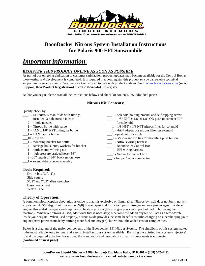
Theory of Operation: A common misconception about nitrous oxide is that it is explosive or flammable. Nitrous by itself does not burn, nor is it explosive. At 565 deg. F, nitrous oxide (N20) breaks apart and forms two parts nitrogen and one part oxygen. Inside an engine, this added oxygen speeds up the combustion process (the nitrogen plays an important part in buffering the reaction). Whenever nitrous is used, additional fuel is necessary; otherwise the added oxygen will act as a blow-torch inside your engine. When used properly, nitrous oxide provides the same benefits as turbo charging or supercharging your engine (extra power is made by burning more fuel and oxygen), but without the added cost or complexities. Below is a diagram of the major components of the Boondocker EFI Nitrous System. The simplicity of this system makes it the most reliable, easy to tune, and easy to install nitrous system available. By using the existing fuel system (injectors) to add the required extra fuel for nitrous, the complexity and unreliability of extra components is eliminated. (continued on next page)
BoonDocker Liquid Nitrous – 1589 Hollipark Dr. Idaho Falls, ID 83401 – (208) 542-4411 website: www.boondockers.com - email: [email protected]
Revised 01-21-05 Page 2 of 11
2
A pressure transducer is used to monitor bottle pressure. Fluctuations in bottle temperature greatly affect nitrous pressure, which affects nitrous delivery. Once the system is tuned, the Control Box will automatically adjust the fuel delivery as nitrous pressure varies, thus making this system safe, reliable, and easy to use.
Part I – Bottle Installation A. Bottle Valve Fittings Insert the 4AN x 1/8” NPT fitting into the bottle valve. Use Teflon tape to seal the threads – be sure not to get tape inside the threads! B. Bottle Mounting Position With nitrous in the bottle, both nitrous liquid and nitrous gas are present under high pressure (760psi at 70 deg F). Due to gravity and acceleration forces, the liquid portion of the nitrous will be at the bottom and rearward parts of the bottle. For this nitrous system to work properly, it is important that nitrous liquid be drawn from the bottle. Nitrous vapor will cause a significant decrease in performance. We prefer not to use a siphon tube inside the bottle since the tube can sometimes come loose and move around inside the bottle. This means the bottle must be mounted so the valve is pointed down and towards the back of the sled as shown.
Front of snowmobile
20 deg to 90 deg Rear of snowmobile
BoonDocker Liquid Nitrous – 1589 Hollipark Dr. Idaho Falls, ID 83401 – (208) 542-4411 website: www.boondockers.com - email: [email protected]
Revised 01-21-05 Page 3 of 11
3
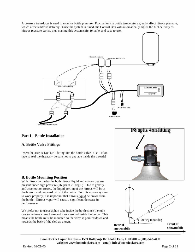
C. Bottle Bracket If the stock exhaust can is used, mount the bracket so it is oriented as shown in fig 2a. Note the following:
1. Mount the saddle bracket to the left foot rest, you will need to relocate factory wiring through the foot rest instead of in front of it.
2. Be very careful that the bottle or the hose does not interfere with the clutch. Refer to fig 3
For machines with after-market exhaust you can also mount the nitrous bottle next to the exhaust can, either in front (refer to fig 2b) and bolt bracket to belly pan or behind exhaust and bolt to foot rest.
The bottle clamp will fit through the D-shaped holes and around the outside of the bracket.
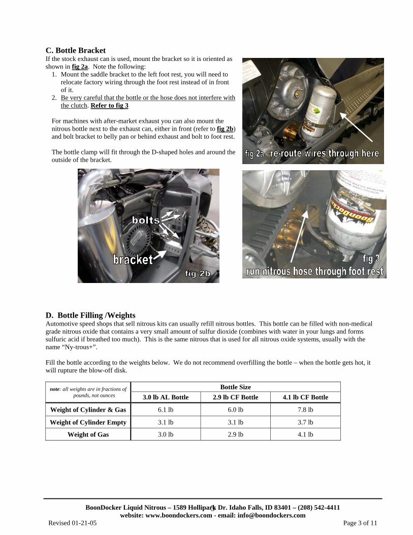
D. Bottle Filling /Weights Automotive speed shops that sell nitrous kits can usually refill nitrous bottles. This bottle can be filled with non-medical grade nitrous oxide that contains a very small amount of sulfur dioxide (combines with water in your lungs and forms sulfuric acid if breathed too much). This is the same nitrous that is used for all nitrous oxide systems, usually with the name “Ny-trous+”. Fill the bottle according to the weights below. We do not recommend overfilling the bottle – when the bottle gets hot, it will rupture the blow-off disk.
note: all weights are in fractions of pounds, not ounces
Bottle Size 3.0 lb AL Bottle 2.9 lb CF Bottle 4.1 lb CF Bottle
Weight of Cylinder & Gas 6.1 lb 6.0 lb 7.8 lb
Weight of Cylinder Empty 3.1 lb 3.1 lb 3.7 lb
Weight of Gas 3.0 lb 2.9 lb 4.1 lb
BoonDocker Liquid Nitrous – 1589 Hollipark Dr. Idaho Falls, ID 83401 – (208) 542-4411 website: www.boondockers.com - email: [email protected]
Revised 01-21-05 Page 4 of 11
4
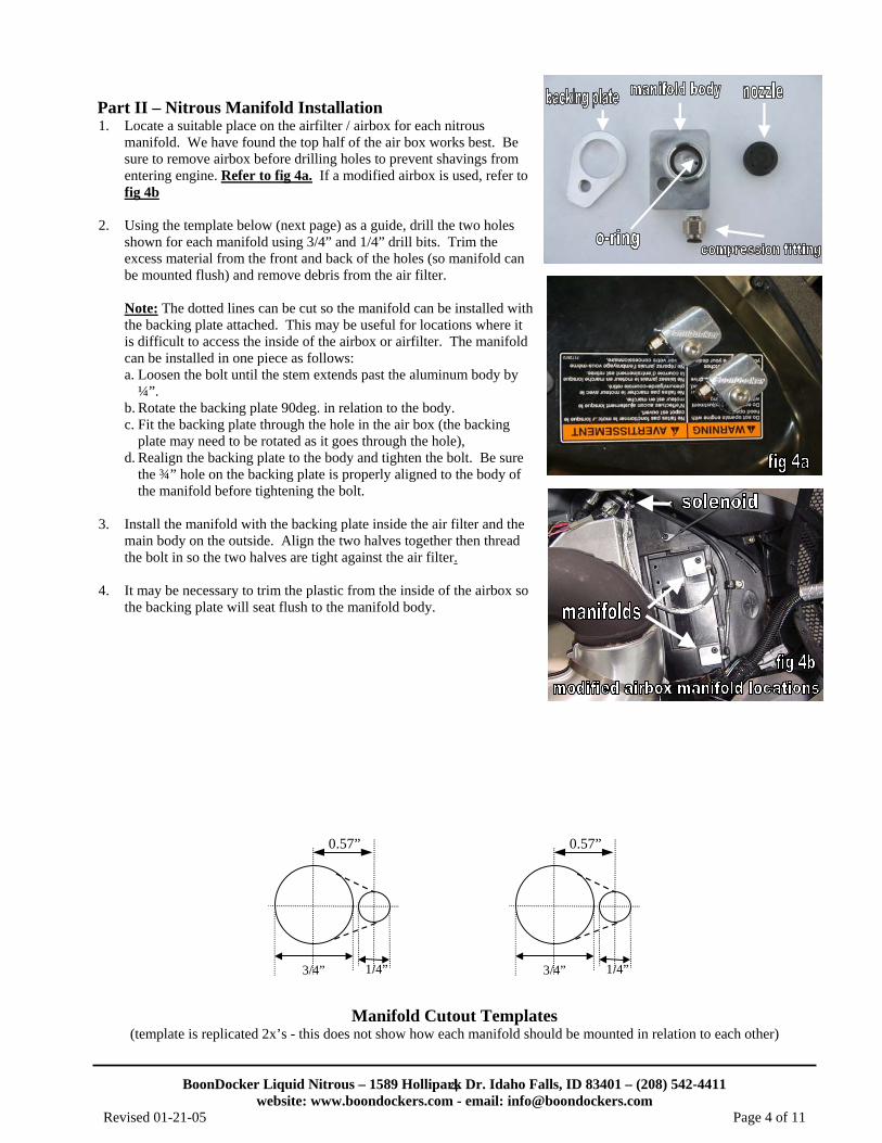
Part II – Nitrous Manifold Installation 1. Locate a suitable place on the airfilter / airbox for each nitrous
manifold. We have found the top half of the air box works best. Be sure to remove airbox before drilling holes to prevent shavings from entering engine. Refer to fig 4a. If a modified airbox is used, refer to fig 4b
2. Using the template below (next page) as a guide, drill the two holes shown for each manifold using 3/4” and 1/4” drill bits. Trim the excess material from the front and back of the holes (so manifold can be mounted flush) and remove debris from the air filter. Note: The dotted lines can be cut so the manifold can be installed with the backing plate attached. This may be useful for locations where it is difficult to access the inside of the airbox or airfilter. The manifold can be installed in one piece as follows: a. Loosen the bolt until the stem extends past the aluminum body by
¼”. b. Rotate the backing plate 90deg. in relation to the body. c. Fit the backing plate through the hole in the air box (the backing
plate may need to be rotated as it goes through the hole), d. Realign the backing plate to the body and tighten the bolt. Be sure
the ¾” hole on the backing plate is properly aligned to the body of the manifold before tightening the bolt.
3. Install the manifold with the backing plate inside the air filter and the
main body on the outside. Align the two halves together then thread the bolt in so the two halves are tight against the air filter.
4. It may be necessary to trim the plastic from the inside of the airbox so
the backing plate will seat flush to the manifold body.
0.57”
3/4” 1/4”
0.57”
3/4” 1/4”
Manifold Cutout Templates
(template is replicated 2x’s - this does not show how each manifold should be mounted in relation to each other)
BoonDocker Liquid Nitrous – 1589 Hollipark Dr. Idaho Falls, ID 83401 – (208) 542-4411 website: www.boondockers.com - email: [email protected]
Revised 01-21-05 Page 5 of 11
5
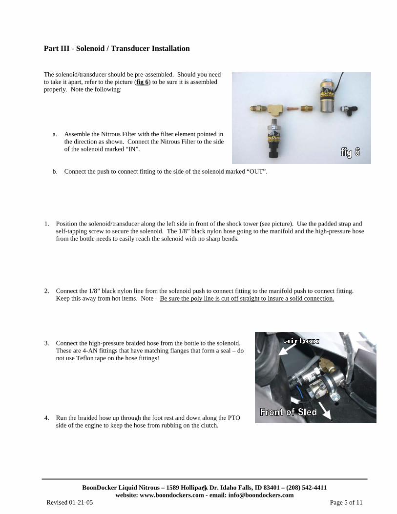
Part III - Solenoid / Transducer Installation The solenoid/transducer should be pre-assembled. Should you need to take it apart, refer to the picture (fig 6) to be sure it is assembled properly. Note the following:
a. Assemble the Nitrous Filter with the filter element pointed in the direction as shown. Connect the Nitrous Filter to the side of the solenoid marked “IN”.
b. Connect the push to connect fitting to the side of the solenoid marked “OUT”. 1. Position the solenoid/transducer along the left side in front of the shock tower (see picture). Use the padded strap and
self-tapping screw to secure the solenoid. The 1/8” black nylon hose going to the manifold and the high-pressure hose from the bottle needs to easily reach the solenoid with no sharp bends.
2. Connect the 1/8” black nylon line from the solenoid push to connect fitting to the manifold push to connect fitting.
Keep this away from hot items. Note – Be sure the poly line is cut off straight to insure a solid connection. 3. Connect the high-pressure braided hose from the bottle to the solenoid.
These are 4-AN fittings that have matching flanges that form a seal – do not use Teflon tape on the hose fittings!
4. Run the braided hose up through the foot rest and down along the PTO
side of the engine to keep the hose from rubbing on the clutch.
BoonDocker Liquid Nitrous – 1589 Hollipark Dr. Idaho Falls, ID 83401 – (208) 542-4411 website: www.boondockers.com - email: [email protected]
Revised 01-21-05 Page 6 of 11
6
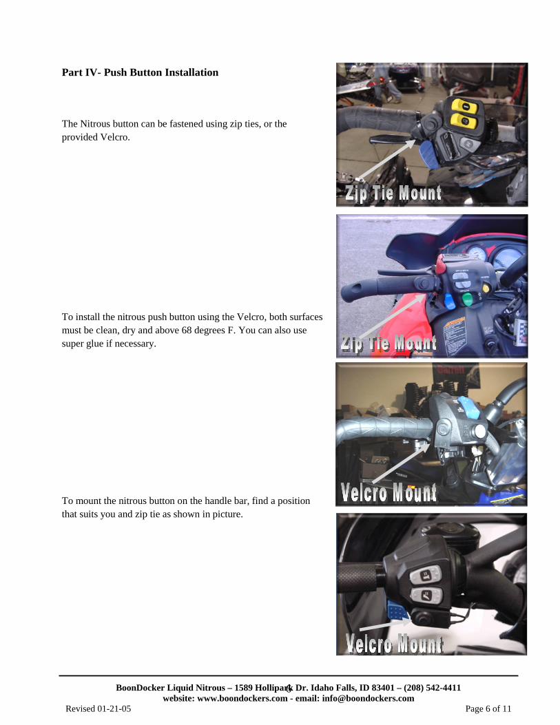
Part IV- Push Button Installation
The Nitrous button can be fastened using zip ties, or the provided Velcro.
To install the nitrous push button using the Velcro, both surfaces must be clean, dry and above 68 degrees F. You can also use super glue if necessary.
To mount the nitrous button on the handle bar, find a position that suits you and zip tie as shown in picture.
BoonDocker Liquid Nitrous – 1589 Hollipark Dr. Idaho Falls, ID 83401 – (208) 542-4411 website: www.boondockers.com - email: [email protected]
Revised 01-21-05 Page 7 of 11
7
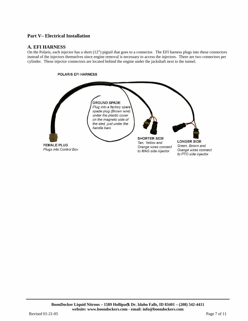
Part V– Electrical Installation A. EFI HARNESS On the Polaris, each injector has a short (12”) pigtail that goes to a connector. The EFI harness plugs into these connectors instead of the injectors themselves since engine removal is necessary to access the injectors. There are two connectors per cylinder. These injector connectors are located behind the engine under the jackshaft next to the tunnel.
BoonDocker Liquid Nitrous – 1589 Hollipark Dr. Idaho Falls, ID 83401 – (208) 542-4411 website: www.boondockers.com - email: [email protected]
Revised 01-21-05 Page 8 of 11
8
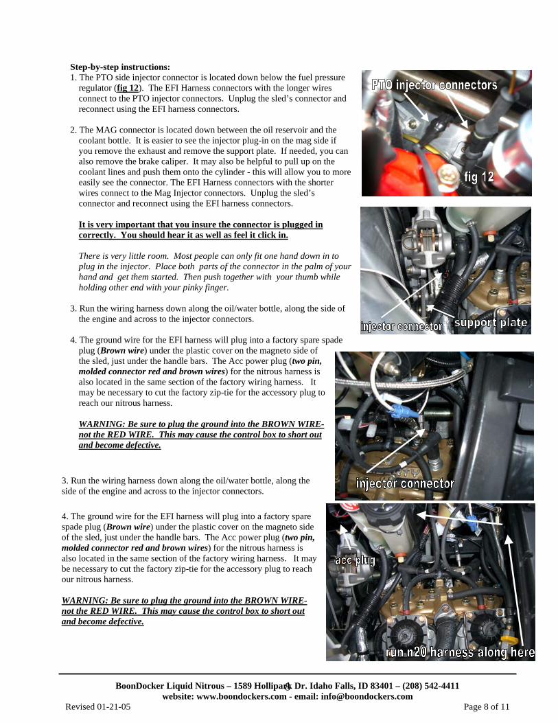
Step-by-step instructions: 1. The PTO side injector connector is located down below the fuel pressure
regulator (fig 12). The EFI Harness connectors with the longer wires connect to the PTO injector connectors. Unplug the sled’s connector and reconnect using the EFI harness connectors.
2. The MAG connector is located down between the oil reservoir and the
coolant bottle. It is easier to see the injector plug-in on the mag side if you remove the exhaust and remove the support plate. If needed, you can also remove the brake caliper. It may also be helpful to pull up on the coolant lines and push them onto the cylinder - this will allow you to more easily see the connector. The EFI Harness connectors with the shorter wires connect to the Mag Injector connectors. Unplug the sled’s connector and reconnect using the EFI harness connectors.
It is very important that you insure the connector is plugged in correctly. You should hear it as well as feel it click in.
There is very little room. Most people can only fit one hand down in to plug in the injector. Place both parts of the connector in the palm of your hand and get them started. Then push together with your thumb while holding other end with your pinky finger.
3. Run the wiring harness down along the oil/water bottle, along the side of
the engine and across to the injector connectors. 4. The ground wire for the EFI harness will plug into a factory spare spade
plug (Brown wire) under the plastic cover on the magneto side of the sled, just under the handle bars. The Acc power plug (two pin, molded connector red and brown wires) for the nitrous harness is also located in the same section of the factory wiring harness. It may be necessary to cut the factory zip-tie for the accessory plug to reach our nitrous harness.
WARNING: Be sure to plug the ground into the BROWN WIRE-not the RED WIRE. This may cause the control box to short out and become defective.
3. Run the wiring harness down along the oil/water bottle, along the side of the engine and across to the injector connectors. 4. The ground wire for the EFI harness will plug into a factory spare spade plug (Brown wire) under the plastic cover on the magneto side of the sled, just under the handle bars. The Acc power plug (two pin, molded connector red and brown wires) for the nitrous harness is also located in the same section of the factory wiring harness. It may be necessary to cut the factory zip-tie for the accessory plug to reach our nitrous harness. WARNING: Be sure to plug the ground into the BROWN WIRE-not the RED WIRE. This may cause the control box to short out and become defective.
BoonDocker Liquid Nitrous – 1589 Hollipark Dr. Idaho Falls, ID 83401 – (208) 542-4411 website: www.boondockers.com - email: [email protected]
Revised 01-21-05 Page 9 of 11
9
B. NITROUS HARNESS
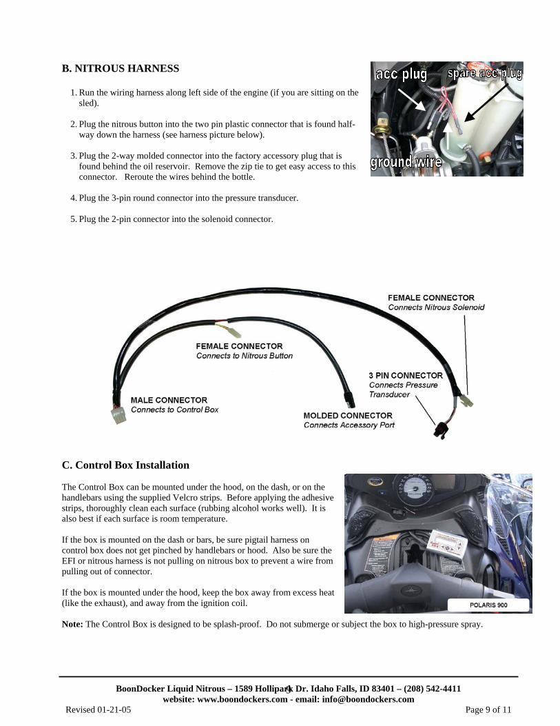
1. Run the wiring harness along left side of the engine (if you are sitting on the sled).
2. Plug the nitrous button into the two pin plastic connector that is found half-
way down the harness (see harness picture below). 3. Plug the 2-way molded connector into the factory accessory plug that is
found behind the oil reservoir. Remove the zip tie to get easy access to this connector. Reroute the wires behind the bottle.
4. Plug the 3-pin round connector into the pressure transducer. 5. Plug the 2-pin connector into the solenoid connector.
C. Control Box Installation The Control Box can be mounted under the hood, on the dash, or on the handlebars using the supplied Velcro strips. Before applying the adhesive strips, thoroughly clean each surface (rubbing alcohol works well). It is also best if each surface is room temperature. If the box is mounted on the dash or bars, be sure pigtail harness on control box does not get pinched by handlebars or hood. Also be sure the EFI or nitrous harness is not pulling on nitrous box to prevent a wire from pulling out of connector. If the box is mounted under the hood, keep the box away from excess heat (like the exhaust), and away from the ignition coil. Note: The Control Box is designed to be splash-proof. Do not submerge or subject the box to high-pressure spray.
BoonDocker Liquid Nitrous – 1589 Hollipark Dr. Idaho Falls, ID 83401 – (208) 542-4411 website: www.boondockers.com - email: [email protected]
Revised 01-21-05 Page 10 of 11
10
Part VI - Startup and Tuning Procedures A. Important Notes before using Nitrous:
1. We strongly recommend using high-octane fuel (at least 94 for most stock motors, more for modified motors). We have found that race fuel or race fuel concentrate (made by Torco or Klotz) mixed with premium gas can provide the necessary octane.
2. We also recommend using one size colder spark plug (higher number = colder). In some cases decreasing the spark plug gap an additional .003”-.005” (around .018-.020”) achieves best results.
3. Be sure to use filtered nitrous – always use a filter when filling your bottle! 4. When tuning the system, do not use nitrous for more than 2 seconds at a time. Once the system is properly tuned
(see steps below), we recommend not using nitrous for more than 8 seconds at a time. If nitrous is used for longer durations, it is critical that the system be carefully tuned and that no detonation problems are occurring.
B. Startup & Leak Test Procedure The rider must do the following steps every time the bottle is turned on and before doing the fuel adjustment procedure.
1. With the engine off, open the bottle valve and check for leaks. Shut the bottle valve off. With the valve shut, the hose will still have pressure in it.
2. With pressure in the hose and the bottle valve closed, start the engine. Check to make sure the solenoid does not discharge hose pressure.
3. With the engine running (be ready to shut down engine if necessary), open the bottle valve. Push the nitrous button for about one second or less. Engine rpm should increase if the nitrous system is functioning properly.
Warning: Only adjust the Control Box settings according to the steps below.
The steps below should be done with a full nitrous bottle that is at the proper operating temperature (70-90deg F) and pressure (700-1000psi). Make sure the engine is at normal operating temperature. Do not exceed 2 seconds of nitrous use until the fuel adjustment is complete and correct.
This adjustment process should only be performed by an experienced tuner. If you are not an experienced tuner, find someone who is. Remember, safety first!
1. Increase the nitrous fuel adjustment setting on the Control Box until you notice a drop in the power increase when using nitrous. When this occurs, you are rich. Be sure you have reached this point before proceeding. Note this adjustment setting.
2. Only after step 1 is complete, start reducing the fuel setting. Continue reducing the fuel setting until a maximum
power increase is obtained. This can be determined by noticing your maximum RPM.
3. If the fuel is reduced but no power increase is noticed from the previous setting, this means you are lean. Note this adjustment setting.
4. Increase the fuel setting back to where it was before no additional power increase was noted in step 3. This
setting should be somewhere between the rich and lean settings. It is best to stay on the rich side.
5. After this adjustment is made, if the engine does not run perfectly smooth when using nitrous, do not use it! If the exhaust note does not sound clean, the cause is likely detonation, which can quickly destroy the engine. Use higher octane fuel, add more ignition retard, reduce the engine’s compression, or reduce the amount of nitrous (see next section for changing nozzles) before using nitrous again.
BoonDocker Liquid Nitrous – 1589 Hollipark Dr. Idaho Falls, ID 83401 – (208) 542-4411 website: www.boondockers.com - email: [email protected]
Revised 01-21-05 Page 11 of 11
11
Part VII – Changing Nitrous Manifold Nozzles It is possible to increase/decrease the amount of nitrous the nitrous manifold sprays by replacing the ¾” nozzles with nozzles with more/less orifice holes. In general, each orifice hole that is sprayed is equivalent to a 4-5hp increase. Read this before you increase nitrous! Be sure your engine is working good before you decide to increase the amount of nitrous. If you are not getting the power increase you are expecting with the original setup, something is likely wrong. Review the nitrous tuning procedure and verify that you can add fuel so you know there is too much fuel. From there, if leaning the nitrous fuel adjustment setting does not produce an increase in power, one of the following problems may exist: 1. Be sure your bottle is full, at the correct temperature (70-90 deg), and positioned correctly so the valve picks up liquid
nitrous. The system will not work properly if nitrous vapor is being picked up or if the bottle is too cold. 2. Your engine could be detonating. Detonation can occur if your compression ratio is high, your timing has been
advanced, or you are not using good octane fuel. Listen carefully to the motor - if it does not sound clean and you are not too rich, you are likely detonating.
3. A bad power source or faulty electrical connection may cause the nitrous system to malfunction intermittently.
Carefully check all connections. If necessary, solder all connections. Important Note: A known problem exists on some snowmobiles when the lighting system has been disconnected (often when the hood has been removed). The voltage will be fine at an idle, but when revved up, the voltage regulator will become overloaded and the voltage will drop, causing the nitrous solenoid to no longer work. Either reconnect the headlight so there is enough load on it, or remove the old voltage regulator and replace it with two new regulators wired in parallel (connect both yellow wires together). Both regulators must in good working order and be the exact same type so they both regulate to the same voltage.
4. Dirty nitrous can quickly plug the nitrous filter and obstruct the nitrous delivery. Remove and clean the sintered bronze
filter element by blowing compressed air through it backwards. Always fill your bottle from a filtered source. Installing / Removing Nozzles 1. Remove the nitrous manifold from the air box. 2. Use a 7/32” hex wrench to carefully remove/install a nozzle. Be sure the o-ring is still in place before threading in a
new nozzle. Be very careful not to over tighten the plastic nozzle – it needs to be just snug. 3. If you want to increase nitrous delivery, increase the number of nozzle holes by one per manifold! 4. Retune the control box according to the instructions above any time nitrous delivery amount is changed Part VIII – Warranty, Terms & Conditions Returned Goods – No merchandise will be accepted without prior approval. A RMA number (Return Merchandise Authorization) provided by Boondocker is required before a return will be accepted. A 20% handling and restocking charge will be applied to returned merchandise. No unauthorized returns will be accepted. Limited Warranty – Boondocker warrants its product to the original purchaser against workmanship defects for a period of 90 days, commencing from the date of product delivery to the Consumer. Maximum Liability – The maximum liability of Boondocker in connection with this warranty shall not under any circumstances exceed the price of the product claimed to be defective.


![Technical Bulletin - Polaris - Polaris 9300 Sport & Polaris 9300xi Sport[1]](https://img.pdfslide.us/doc/110x75/553b235d4a7959d8258b463f/technical-bulletin-polaris-polaris-9300-sport-polaris-9300xi-sport1.jpg)