Embed Size (px)
Citation preview

Pointing Accuracy and Stability Analysis of
CMG Control for Nano-satellite “TSUBAME”
Shota Kawajiri1, Hao Ting1, Masanori Matsushita1,
Kyosuke Tawara1 and Saburo Matunaga1,2
1. Department of Mechanical and Aerospace Engineering,
Tokyo Institute of Technology, Japan
2. Institute of Space and Astronautical Science, JAXA, Japan
2015/4/23 110th IAA Symposium on Small Satellites for Earth Observation

2
Outline
Mission
Analysis
Intro.TSUBAME Missions
Mission Requirements
On-Orbit Experimental PlanExperiment
Hardware ConfigurationADCS
OverviewDataflow in the Missions
Earth
Observation Mission
Astronomical
Observation Mission
Analysis Environment
Results and ProblemConclusion
Characteristics of TSUBAME
TSUBAME Overview
3
Outline
Mission
Analysis
Intro.TSUBAME Missions
Mission Requirements
On-Orbit Experimental PlanExperiment
Hardware ConfigurationADCS
OverviewDataflow in the Missions
Earth
Observation Mission
Astronomical
Observation Mission
Analysis Environment
Results and ProblemConclusion
Characteristics of TSUBAME
TSUBAME Overview

Micro Satellite “TSUBAME”
Contents of the Presentation
Verification of the mission performance conducted
before the launch
On-orbit experimental plan
4
TSUBAME Overview
Developed by Matunaga Lab.
at Tokyo Institute of Technology
50 kg & 50 cm cubed
Launched on 6 Nov., 2014
Released into a 500 km
sun-synchronous orbit (LTDN:10:58)

5
Outline
Mission
Analysis
Intro.TSUBAME Missions
Mission Requirements
On-Orbit Experimental PlanExperiment
Hardware ConfigurationADCS
OverviewDataflow in the Missions
Earth
Observation Mission
Astronomical
Observation Mission
Analysis Environment
Results and ProblemConclusion
Characteristics of TSUBAME
TSUBAME Overview

6
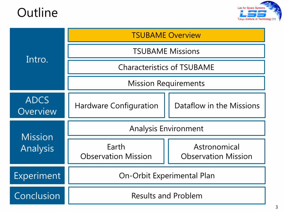
TSUBAME Missions
Micro CMG Demonstration
Earth
Observation
Astronomical
Observation

7
TSUBAME Missions
Micro CMG Demonstration
Earth
Observation
Astronomical
Observation

Demonstrate high speed & high accuracy maneuvering
with newly developed micro Control Momentum Gyros
(CMGs)
8
Micro CMG Demonstration Mission
CMGs: high efficiency
Reaction Wheel CMG
Power/Torque 250-2100 W/Nm 170 W/Nm
Weight/Torque 28- 290 kg/Nm 19 kg/Nm
Pyramid configuration
4 CMGs
skew angle: 54.7 deg
Micro CMG
9
TSUBAME Missions
Micro CMG Demonstration
Earth
Observation
Astronomical
Observation

With a small high resolution optical camera
Accurate and agile pointing using micro CMGs
10
Earth Observation Mission
CameraMultiple
point shooting
Continuous fixed
point shooting Resolution: 14 m
Developed by Kimura Lab.
at Tokyo University of Science

11
TSUBAME Missions
Micro CMG Demonstration
Earth
Observation
Astronomical
Observation

12
Astronomical Observation Mission
HXCP
GRB(NASA)
Gamma-Ray Burst (GRB)
Astronomical phenomena
Occurs suddenly at a random location
Lasts from a few seconds to 100 seconds
Observation in 15 seconds is desired
Sensors mounted on TSUBAME
Five Wide-field Burst Monitors (WBMs)
to detect GRBs
One Hard X-ray Compton Polarimeter (HXCP)
to observe GRBs
Developed by Kawai Lab.
at Tokyo Institute of Technology5 WBMs
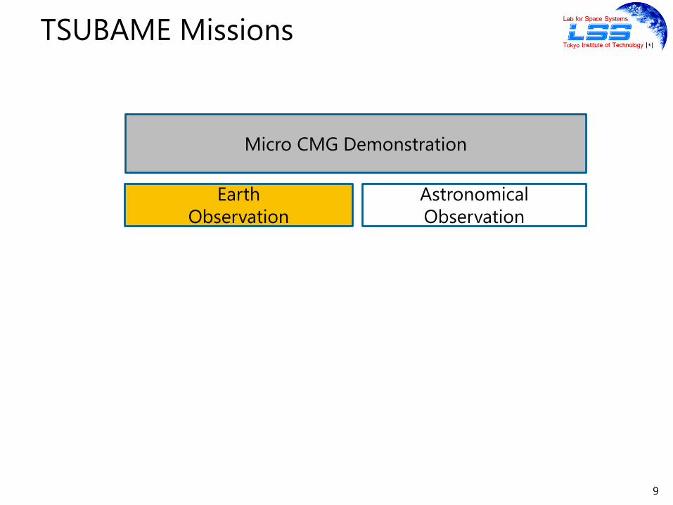
1. A GRB occurs
2. Detects the GRB and determines the direction using
the WBMs
3. Finishes Maneuver in 15 seconds using the micro CMGs
4. Observes a GRB using the HXCP
13
Astronomical Observation Mission
Observation sequence of a GRB

14
Outline
Mission
Analysis
Intro.TSUBAME Missions
Mission Requirements
On-Orbit Experimental PlanExperiment
Hardware ConfigurationADCS
OverviewDataflow in the Missions
Earth
Observation Mission
Astronomical
Observation Mission
Analysis Environment
Results and ProblemConclusion
Characteristics of TSUBAME
TSUBAME Overview

Unfeasible Missions
15
Characteristics of Micro Satellites
Feasibility
of Missions
TSUBAME
Challenging Missions with Low Cost
Development with Research
Requirements
Best effort
Performs missions in the range
of the performance even if the
requirements are not satisfiedNormal Satellites
Feasible Missions with High Cost
Requirements
Guaranteed to be satisfied
Pleiades (ESA)
Cost

16
Outline
Mission
Analysis
Intro.
Mission Requirements
On-Orbit Experimental PlanExperiment
Hardware ConfigurationADCS
OverviewDataflow in the Missions
Earth
Observation Mission
Astronomical
Observation Mission
Analysis Environment
Results and ProblemConclusion
Characteristics of TSUBAME
TSUBAME Missions
TSUBAME Overview

Mission Requirements
17
Earth
Observation
Astronomical
Observation
Accuracy
[deg]
0.72 3.0
Stability
[deg/s]
0.50 N/A
Agility N/A 90 deg maneuver
in 15 seconds
Best Effort Requirements

18
Outline
Mission
Analysis
Intro.TSUBAME Missions
Mission Requirements
On-Orbit Experimental PlanExperiment
Hardware ConfigurationADCS
OverviewDataflow in the Missions
Earth
Observation Mission
Astronomical
Observation Mission
Analysis Environment
Results and ProblemConclusion
Characteristics of TSUBAME
TSUBAME Overview
19
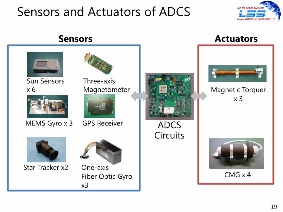
Sensors and Actuators of ADCS
MEMS Gyro x 3
Star Tracker x2
Magnetic Torquer
x 3
CMG x 4
ADCSCircuits
Sensors Actuators
GPS Receiver
Sun Sensors
x 6
Three-axis
Magnetometer
One-axis
Fiber Optic Gyro
x3
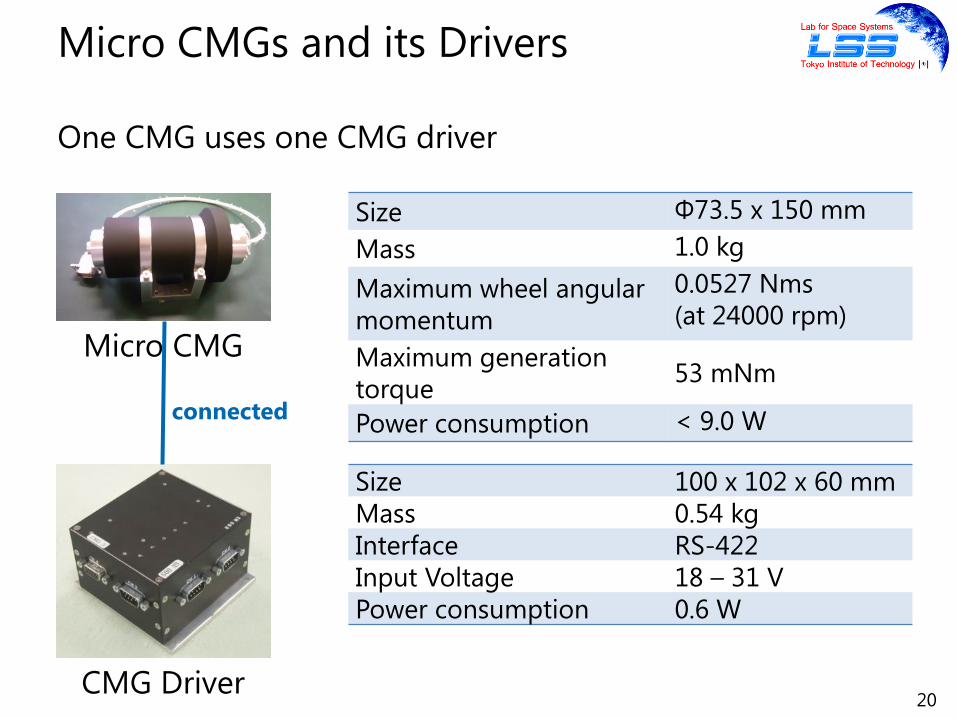
One CMG uses one CMG driver
Size Φ73.5 x 150 mm
Mass 1.0 kg
Maximum wheel angular
momentum
0.0527 Nms
(at 24000 rpm)
Maximum generation
torque53 mNm
Power consumption < 9.0 W
20
Micro CMGs and its Drivers
Size 100 x 102 x 60 mm
Mass 0.54 kg
Interface RS-422
Input Voltage 18 – 31 V
Power consumption 0.6 W
Micro CMG
CMG Driver
connected

21
Two CPUs of ADCS
Obtains sensor data
Receives CAN commands
Saves data to NAND
flash memory
Determines orbit
and attitude
Controls attitude
Drives actuators
Hardware configuration

22
Outline
Mission
Analysis
Intro.
On-Orbit Experimental PlanExperiment
Hardware ConfigurationADCS
OverviewDataflow in the Missions
Earth
Observation Mission
Astronomical
Observation Mission
Analysis Environment
Results and ProblemConclusion
TSUBAME Missions
Mission Requirements
Characteristics of TSUBAME
TSUBAME Overview

GPSR, STTs, FOGs and CMGs are used in the mission
23
ADCS Dataflow in the Missions
GPSR
STTs
FOGs
CMGs
EKF
EKF
UKF
GSR
WSR
QF
t
q
ω ω est
q est
restr
Tref δ ref
.
Ω, δ
Schematic of Implemented Algorithms
and Dataflow for the CMG System of TSUBAME.

24
Outline
Mission
Analysis
Intro.
On-Orbit Experimental PlanExperiment
Hardware ConfigurationADCS
OverviewDataflow in the Missions
Earth
Observation Mission
Astronomical
Observation Mission
Analysis Environment
Results and ProblemConclusion
TSUBAME Missions
Mission Requirements
Characteristics of TSUBAME
TSUBAME Overview

Software in the Loop Simulation (SiLS)
25
Analysis Environment
Control
Value
Sensor
Data
Control
Torque
Space Environment
Attitude Dynamics
Model
Sensor
Models
Actuator
Models
Σ
Disturbance
Torque
Orbit
Attitude
Embedded Software
Determine
Orbit & Attitude
Attitude
Control
Configuration of the SiLS

26
Outline
Mission
Analysis
Intro.
On-Orbit Experimental PlanExperiment
Hardware ConfigurationADCS
OverviewDataflow in the Missions
Earth
Observation Mission
Astronomical
Observation Mission
Analysis Environment
Results and ProblemConclusion
TSUBAME Missions
Mission Requirements
Characteristics of TSUBAME
TSUBAME Overview

Continuous fixed point shooting
Target point: Tokyo Institute of Technology
Pointing control: Starts on 13 Mar., 2015 at 1:50 (UTC)
Shooting duration: 1:53 - 1:58
27
Simulation Scenario
1:55:30
1:58:00
1:53:00
Tokyo Institute
of Technology
Diagram of a simulation of continuous fixed point shooting
28
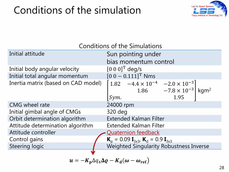
Conditions of the simulation
Initial attitude Sun pointing under
bias momentum controlInitial body angular velocity 0 0 0 T deg/s
Initial total angular momentum 0 0 − 0.111 T Nms
Inertia matrix (based on CAD model) 1.82 −4.4 × 10⁻⁴ −2.0 × 10⁻³
1.86 −7.8 × 10⁻³
𝑆𝑦𝑚. 1.95kgm2
CMG wheel rate 24000 rpm
Initial gimbal angle of CMGs 320 deg
Orbit determination algorithm Extended Kalman Filter
Attitude determination algorithm Extended Kalman Filter
Attitude controller Quaternion feedback
Control gains Kp = 0.09 I3x3, Kd = 0.9 I3x3
Steering logic Weighted Singularity Robustness Inverse
𝒖 = −𝑲𝐩Δ𝑞4𝚫𝝔 − 𝑲𝐝(𝝎 − 𝝎𝐫𝐞𝐟
Conditions of the Simulations
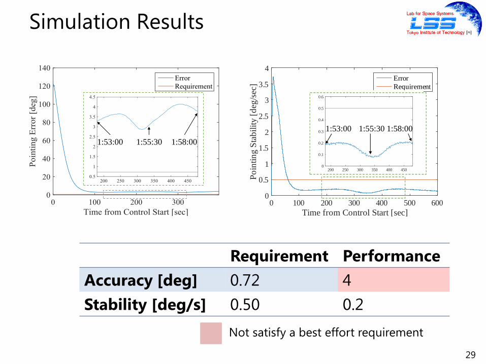
Requirement Performance
Accuracy [deg] 0.72 4
Stability [deg/s] 0.50 0.2
29
Simulation Results
1:53:00 1:55:30 1:58:00
Time from Control Start [sec]0 100 200 300 400 500 600
Po
inti
ng
Sta
bil
ity
[d
eg/s
ec]
0
0.5
1
1.5
2
2.5
3
3.5
4
Error
Requirement
200 250 300 350 400 4500
0.1
0.2
0.3
0.4
0.5
0.6
1:53:00 1:55:30 1:58:00
Not satisfy a best effort requirement

Time from Control Start [sec]0 100 200 300 400 500 600
Po
inti
ng
Err
or
[deg
]
0
20
40
60
80
100
120
140
Error
Requirement
200 250 300 350 400 4500
0.5
1
1.5
2
2.5
3
3.5
4
4.5
Larger Kp yields better accuracy?
30
Discussion
e.g. Gain scheduling
An Improved controller is required
Attitude Oscillation
Kp = 0.12 I3x3, Kd = 0.9 I3x3
31
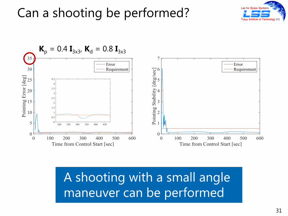
Can a shooting be performed?
Kp = 0.4 I3x3, Kd = 0.8 I3x3
A shooting with a small angle
maneuver can be performed
32
Outline
Mission
Analysis
Intro.
On-Orbit Experimental PlanExperiment
Hardware ConfigurationADCS
OverviewDataflow in the Missions
Earth
Observation Mission
Astronomical
Observation Mission
Analysis Environment
Results and ProblemConclusion
TSUBAME Missions
Mission Requirements
Characteristics of TSUBAME
TSUBAME Overview

GRB Direction
Zenith 𝜃: 90 deg
Azimuth 𝜙: random
33
Simulation Scenario
Zenith 𝜃 and Azimuth 𝜙 of a GRB Direction
GRB Direction
Azimuth
Zenith
90 deg maneuver

Monte Carlo Simulation
Three hundred cases
Azimuth of a GRB is determined by a random number
Initial Conditions
the same as that of the earth observation
34
Conditions of the simulation

Settling Time: time to satisfy the accuracy requirement
Fastest : 30.1 seconds: not satisfy the agility requirement
Slowest: 98.0 seconds (with singularity problem)
35
Simulation Results (Best vs Worst)
Time from Control Start [sec]0 20 40 60 80 100
Po
inti
ng
Err
or
[deg
]
0
20
40
60
80
100
The fastest
The slowest
Requirement
30.1 sec 98.0 sec
An Improved steering logic is required

36
Simulation Results (Statistics)
Requirement Performance
Accuracy [deg] 3 Smaller than 3
Agility [sec] 15 42.5
Not satisfy a best effort requirement

Discussed with a science team
37
Reconsider the Agility Requirement
45 deg maneuver in 15 seconds is sufficient
to observe 3 significant GRBs in a year

GRB Direction
Zenith 𝜃: 45 deg
Azimuth 𝜙: random
38
Simulation Scenario
Zenith 𝜃 and Azimuth 𝜙 of a GRB Direction
GRB Direction
Azimuth
Zenith
45 deg maneuver

39
Simulation Results
Requirement Performance
Accuracy [deg] 3 Smaller than 3
Agility [sec] 15 24.5
Not satisfy a best effort requirement

Increasing the size of solar array paddles
large inertia moment of the flight model
40
Discussion -Reason for slow maneuver-
Inertia Moment
of the Flight model
Assumed value
in the early development stage
1.9 kgm2 > 1.2 kgm2
Larger CMG torque or
smaller inertia moment is required

In this maneuver speed, if size of GRBs are ignored,
TSUBAME can observe about 13 GRBs in a year.
41
How many GRBs can be observed?
Significant GRBs can be observed in a year
Big & significant GRBs Long-lasting and
easy to observe

42
Outline
Mission
Analysis
Intro.
On-Orbit Experimental PlanExperiment
Hardware ConfigurationADCS
OverviewDataflow in the Missions
Earth
Observation Mission
Astronomical
Observation Mission
Analysis Environment
Results and ProblemConclusion
TSUBAME Missions
Mission Requirements
Characteristics of TSUBAME
TSUBAME Overview
Not yet conducted
& maybe will not be conducted
TSUBAME stopped receiving uplink commands
during initial checkout phase
Location of the faults
Peripheral circuit for communication is suspicious
43
On-Orbit Experiment

44
Outline
Mission
Analysis
Intro.
On-Orbit Experimental PlanExperiment
Hardware ConfigurationADCS
OverviewDataflow in the Missions
Earth
Observation Mission
Astronomical
Observation Mission
Analysis Environment
Results and ProblemConclusion
TSUBAME Missions
Mission Requirements
Characteristics of TSUBAME
TSUBAME Overview

Performances in the missions are verified using software
in the loop simulation
Some best effort requirements are not satisfied
TSUBAME can still perform both the earth and
astronomical observation
– Shooting with a small maneuver can be performed
– Significant GRBs can be observed in a year
Future Work
Torque of CMGs, inertia moment, attitude controller and
steering logic should be improved
45
Conclusion
Appendix
46

TSUBAME Overview
Size 450×450×560 mm3
Mass 48.6 kg
Lifetime 1 year
Orbit500 km sun-synchronous
orbit (LTDN:10:58)
Power Supply
Solar cells
(Max. 130 W @ EOL)
Li-Po Battery
(16.2 Ah, 360 Wh)
Max. Power
Consumption68 W
Comm.Amateur Band (1200 bps)
S-Band (Max. 100 kbps)
Launch Date 6 November, 2014
47
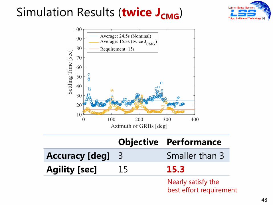
48
Simulation Results (twice JCMG)
Objective Performance
Accuracy [deg] 3 Smaller than 3
Agility [sec] 15 15.3
Nearly satisfy the
best effort requirement