Embed Size (px)
Citation preview
1
Lesson 2: point-to-multipoint wireless planning systems
Advanced Technology in Radiocommunications
POINT‐TO‐MULTIPOINT WIRELESS PLANNING SYSTEMS
Advanced Technology in Radio Communications
Pablo Corral GonzálezCommunications Engineering Department
Signal Theory and Communications Universidad Miguel Hernández
Lesson 2: point-to-multipoint wireless planning systems
Advanced Technology in Radiocommunications
POINT-TO-MULTIPOINT WIRELESS SYSTEMS
2.1. P-T-MP planning system2.2. P-T-MP components2.3. Manufacturers and distributors. 2.4. Market perspectives.2.5. Trials.2.6. Future trends.
2
2
Lesson 2: point-to-multipoint wireless planning systems
Advanced Technology in Radiocommunications
OBJECTIVES To study the different things that affect to the cells sizecalculation in a P-T-MP system millimetric bands
To show the steps in a P-T-MP system design
To report about products and manufacturers and to emphasizeabout the key parameters of the different subsystems
To give a global vision about market trends, such as theforecasts of P-T-MP system developments
3
Lesson 2: point-to-multipoint wireless planning systems
Advanced Technology in Radiocommunications
P-T-MP PLANNING SYSTEM
1. INTRODUCTION.
2. DEGRADATION MECHANISMS
3. THEORETICAL CELLULAR PLANNING3.1. Channeling.3.2. Cell shapes.3.3. Frequency plans.3.4. Cell sizes.
4. STATISTIC MODELING.4.1. Channel modeling.4.2. Hypothesis.
4

3
Lesson 2: point-to-multipoint wireless planning systems
Advanced Technology in Radiocommunications
1. INTRODUCTION
2.1. P-T-MP PLANNING SYSTEM (1):
INTRODUCTION
Probably the hardest part in a wireless network deploymentis the planification
In P-T-MP systems, the location choice and the correct size of cells is a critical point to make sure the network is going tosatisfy QoS ratios and operator costs.
So, a vital question is the calculation of the cell size
5
Lesson 2: point-to-multipoint wireless planning systems
Advanced Technology in Radiocommunications
2. DEGRADATION MECHANISMS
There are different mechanisms to calculate the balance of powers in a radio link
• Attenuation by free-space propagation.• Atmospheric attenuation (gases, clouds and fog).• Attenuation and Scattering in rain and othershydrometeors.• Attenuation by vegetation.• Attenuation caused by buildings: diffraction.
2.1. P-T-MP PLANNING SYSTEM (2):
DEGRADATION MECHANISM (1)
We pretend to characterize the model in the millimetric band
6
4
Lesson 2: point-to-multipoint wireless planning systems
Advanced Technology in Radiocommunications
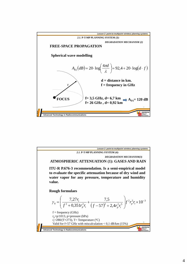
FREE-SPACE PROPAGATION
FOCUS
r
Spherical wave modelling
fdd
dBAEL
log204,92
4log20
d = distance in km.f = frequency in GHz
f= 3,5 GHz, d= 6,7 km f= 26 GHz , d= 0,92 km
AFS= 120 dB
2.1. P-T-MP PLANNING SYSTEM (3):
DEGRADATION MECHANISM (2)
7
Lesson 2: point-to-multipoint wireless planning systems
Advanced Technology in Radiocommunications
ATMOSPHERIC ATTENUATION (1): GASES AND RAIN
ITU-R P.676-3 recommendation. Is a semi-empirical modelto evaluate the specific attenuation because of dry wind andwater vapor for any pressure, temperature and humidityvalue.
Rough formulaes
322
522220 104,257
5,7
351,0
27,7
tp
tptp
t rrfrrfrrf
r
f = frequency (GHz)rp=p/1013, p=pressure (hPa)rt=288/(T+273), T= Temperature (ºC)Valid for f<57 GHz with miscalculation < 0,1 dB/km (15%)
2.1. P-T-MP PLANNING SYSTEM (4):
DEGRADATION MECHANISM(3)
8

5
Lesson 2: point-to-multipoint wireless planning systems
Advanced Technology in Radiocommunications
ATMOSPHERIC ATTENUATION (2): GASES AND RAIN
Att
enu
atio
n(d
B/k
m)
Frequency (GHz)10
0
101
102
103
10-3
10-2
10-1
100
101
102
T = 25º
AATM = 0,0065
AATM = 0,0923
WOATMA
2.1. P-T-MP PLANNING SYSTEM (5):
DEGRADATION MECHANISM (4)
9
Lesson 2: point-to-multipoint wireless planning systems
Advanced Technology in Radiocommunications
ATMOSPHERIC ATTENUATION (3): CLOUDS AND FOG
2.1. P-T-MP PLANNING SYSTEM (6):
DEGRADATION MECHANISM (5)
Composition: tiny raindrops, generally r < 0,01 cm
Rayleigh approximation (f < 200 GHz)
MKkmdBA LN )/(
KL: specific attenuation coefficient (dB/km)/(g/m3)M: liquid water density in clouds or fog (g/ m3)
M=0,05 g/ m3 in moderate fog (visibility 100 m)M=0,5 g/ m3 in thick fog (visibility 50 m)
This type of attenuation begins to be notable under100 GHz
ITU-R P.840-2 RECOMMENDATION
10

6
Lesson 2: point-to-multipoint wireless planning systems
Advanced Technology in Radiocommunications
ATTENUATION AND SCATTERING IN RAIN AND ANOTHER HIDRO-METEORS (1)
2.1. P-T-MP PLANNING SYSTEM (7):
DEGRADATION MECHANISM (6)
There are a huge kind of models to predict attenuationcaused by hidro-meteors. Mathematic formulae is sort ofdifficult and takes into account several things, such asraindrops, snowballs or ice particles.
• Dielectric characteristics (Deybe model).• Shape, speed and behavior over the fallen .• Raindrop size distribution (RSD)
11
Lesson 2: point-to-multipoint wireless planning systems
Advanced Technology in Radiocommunications
ATTENUATION AND SCATTERING IN RAIN AND ANOTHER HIDRO-METEORS (2)
2.1. P-T-MP PLANNING SYSTEM (8):
DEGRADATION MECHANISM (7)
RSD (raindrop size distribution) defines the number of raindrops that fall in a unit volume with a radius betweena-da/2, a+da/2
daeNdaan a 0)(
N0=1.6x10⁴ (m3mm-1)=8,2R-0.21 (mm-1)a: radius in mmR: rain intensity (mm/h)
(Marshall-Palmer)
Subsequently Gamma, Weibull, Joss models ...
10-6
104
R=0,25
R=10
R=100
R=150
10-2
0 2 4Raindrop radius (mm)
n(a
)da
(m3 m
m-1
)
12
7
Lesson 2: point-to-multipoint wireless planning systems
Advanced Technology in Radiocommunications
ATTENUATION AND SCATTERING IN RAIN AND ANOTHER HIDRO-METEORS (3)
2.1. P-T-MP PLANNING SYSTEM (9):
DEGRADATION MECHANISM (8)
Ei
KiKs
x
y
z jkrS erformaKKfE
121 ),,(
Scattering properties
Crossed sections
21,Im4
KKfek
QQQ sat
Absorbed power Diffused power
e
13
Lesson 2: point-to-multipoint wireless planning systems
Advanced Technology in Radiocommunications
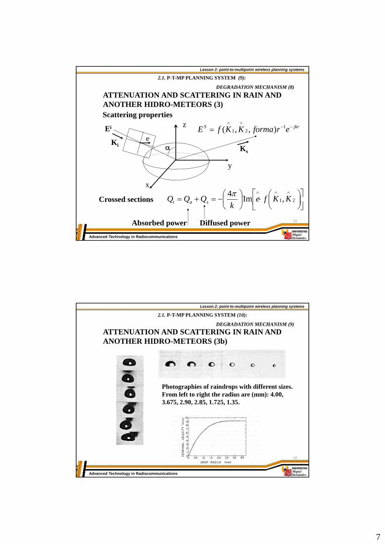
ATTENUATION AND SCATTERING IN RAIN AND ANOTHER HIDRO-METEORS (3b)
2.1. P-T-MP PLANNING SYSTEM (10):
DEGRADATION MECHANISM (9)
Photographies of raindrops with different sizes. From left to right the radius are (mm): 4.00, 3.675, 2.90, 2.85, 1.725, 1.35.
14

8
Lesson 2: point-to-multipoint wireless planning systems
Advanced Technology in Radiocommunications
ATTENUATION AND SCATTERING IN RAIN AND ANOTHER HIDRO-METEORS (4)
2.1. P-T-MP PLANNING SYSTEM (11):
DEGRADATION MECHANISM (10)
Attenuattion calculus
It must be established a relationship between easily measurabledata and rain attenuation
daanaQkmdBA tLL 343.4/
RSD: depends on R
ITU-R P.838 model
kRkmdBALL /
K, : constants tabulated according to the area 15
Lesson 2: point-to-multipoint wireless planning systems
Advanced Technology in Radiocommunications
ATTENUATION AND SCATTERING IN RAIN AND ANOTHER HIDRO-METEORS (5)
2.1. P-T-MP PLANNING SYSTEM (12):
DEGRADATION MECHANISM (11)
0 20 40 60 80 100 120
5
10
15
20
25
30
35
40Rain attenuation ITU-R
Rain intensity R (mm/h)
Att
en
ua
tio
n(d
B/k
m)
V polarization
H polarization
10 GHz
15 GHz
25 GHz
30 GHz50 GHz
16
9
Lesson 2: point-to-multipoint wireless planning systems
Advanced Technology in Radiocommunications
ATTENUATION AND SCATTERING IN RAIN AND ANOTHER HIDRO-METEORS (6)
2.1. P-T-MP PLANNING SYSTEM (13):
DEGRADATION MECHANISM (12)
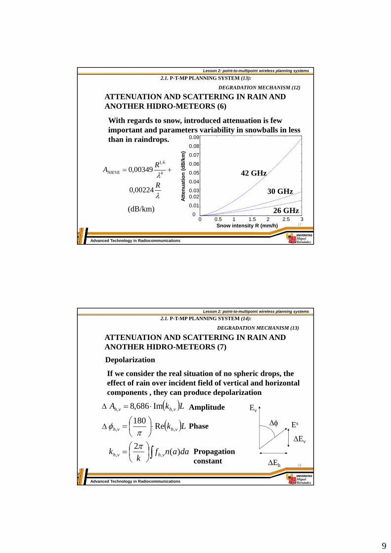
With regards to snow, introduced attenuation is fewimportant and parameters variability in snowballs in lessthan in raindrops.
0 0.5 1 1.5 2 2.5 30
0.01
0.020.03
0.04
0.05
0.06
0.07
0.08
0.09
Snow intensity R (mm/h)
Att
en
ua
tio
n(d
B/k
m)
42 GHz
30 GHz
26 GHz
R
RANIEVE
00224,0
00349,04
6,1
(dB/km)
17
Lesson 2: point-to-multipoint wireless planning systems
Advanced Technology in Radiocommunications
ATTENUATION AND SCATTERING IN RAIN AND ANOTHER HIDRO-METEORS (7)
2.1. P-T-MP PLANNING SYSTEM (14):
DEGRADATION MECHANISM (13)
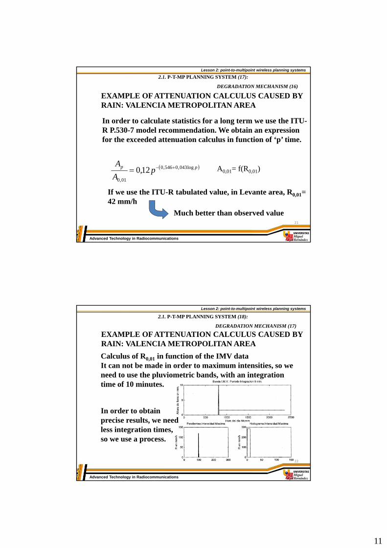
Depolarization
If we consider the real situation of no spheric drops, the effect of rain over incident field of vertical and horizontal components , they can produce depolarization
daanfk
k
Lk
LkA
vhvh
vhvh
vhvh
)(2
Re180
Im686,8
,,
,,
,,
Amplitude
Phase
Propagationconstant
Ev
Es
Ev
Eh
18

10
Lesson 2: point-to-multipoint wireless planning systems
Advanced Technology in Radiocommunications
ATTENUATION AND SCATTERING IN RAIN AND ANOTHER HIDRO-METEORS (8)
2.1. P-T-MP PLANNING SYSTEM (15):
DEGRADATION MECHANISM (14)
Depolarization
h
hh
h
vh
E
EXPI
E
EXPD
log20
log20
v
vv
v
hv
E
EXPI
E
EXPD
log20
log20
f (GHz)100
101
102
-65
-60
-55
-50
-45
-40
-35
-30
-25
-20
-15
XP
D (
dB)
R=12,5 mm/h
R=150 mm/h
19
Lesson 2: point-to-multipoint wireless planning systems
Advanced Technology in Radiocommunications
EXAMPLE OF ATTENUATION CALCULUS CAUSED BY RAIN: VALENCIA METROPOLITAN AREA
2.1. P-T-MP PLANNING SYSTEM (16):
DEGRADATION MECHANISM (15)
The Institute Meteorological of Valencia (IMV) provides the maximum rain fall intensities in a day.
5,42
519.6
2,0)min(
8.124)max(
222,1
2
R
R
R
20
11
Lesson 2: point-to-multipoint wireless planning systems
Advanced Technology in Radiocommunications
EXAMPLE OF ATTENUATION CALCULUS CAUSED BY RAIN: VALENCIA METROPOLITAN AREA
2.1. P-T-MP PLANNING SYSTEM (17):
DEGRADATION MECHANISM (16)
In order to calculate statistics for a long term we use the ITU-R P.530-7 model recommendation. We obtain an expressionfor the exceeded attenuation calculus in function of ‘p’ time.
pp pA
A log043,0546,0
01,0
12,0 A0,01= f(R0,01)
If we use the ITU-R tabulated value, in Levante area, R0,01= 42 mm/h
Much better than observed value21
Lesson 2: point-to-multipoint wireless planning systems
Advanced Technology in Radiocommunications
EXAMPLE OF ATTENUATION CALCULUS CAUSED BY RAIN: VALENCIA METROPOLITAN AREA
2.1. P-T-MP PLANNING SYSTEM (18):
DEGRADATION MECHANISM (17)
Calculus of R0,01 in function of the IMV dataIt can not be made in order to maximum intensities, so weneed to use the pluviometric bands, with an integrationtime of 10 minutes.
In order to obtainprecise results, we needless integration times, so we use a process.
22

12
Lesson 2: point-to-multipoint wireless planning systems
Advanced Technology in Radiocommunications
EXAMPLE OF ATTENUATION CALCULUS CAUSED BY RAIN: VALENCIA METROPOLITAN AREA
2.1. P-T-MP PLANNING SYSTEM (19):
DEGRADATION MECHANISM (18)
Calculus of R0,01 in function of IMV data
25 bands digitizing
R0,01= 6 mm/h
ITU-R isopleth
Pessimist planning
23
Lesson 2: point-to-multipoint wireless planning systems
Advanced Technology in Radiocommunications
2.1. P-T-MP PLANNING SYSTEM (20):
DEGRADATION MECHANISM (19)
ATTENUATION BY VEGETATION (1)
They exist many empiric models of attenuation for a planewave that travels through vegetation in function of thefrequency.This models depend on the type of the tree as well as the typeof the trunk, the thickness of the trunk and the amount of leafs and branchs.
1 2 3 N
h
d
24

13
Lesson 2: point-to-multipoint wireless planning systems
Advanced Technology in Radiocommunications
2.1. P-T-MP PLANNING SYSTEM (21):
DEGRADATION MECHANISM (20)ATTENUATION BY VEGETATION (2)
Models
1. exponential ITU-R. law
CVEG dBfA 3,0 f: frequency (MHz)
d: vegetation depth (m)B, C: tabulated constants.
This model is quite wrong if we compare with experimental measurements. In measurements we can see that exist a penetration depth from which the attenuation do not increasethe value, because the propagation mechanism is thescattering.
25
Lesson 2: point-to-multipoint wireless planning systems
Advanced Technology in Radiocommunications
2.1. P-T-MP PLANNING SYSTEM (22):
DEGRADATION MECHANISM (21)
ATTENUATION BY VEGETATION (3)
mA
dR
mVEG eAA 1Am: Maximum attenuationd: depth vegetation (m)R: initial gradient of the ATT curve.
Am and R can be obtained from the measurements throughregression
2. MAR (Maximum Attenuation Rate)
3. NZG (Non Zero Gradient). MAR improved.
dk
RR
VEG ekdRA0
1R0 : initial rate of attenuationRoo : final rate of attenuationk : final offset
26

14
Lesson 2: point-to-multipoint wireless planning systems
Advanced Technology in Radiocommunications
2.1. P-T-MP PLANNING SYSTEM (23):
DEGRADATION MECHANISM (22)
ATTENUATION BY VEGETATION (4)
0 10 20 30 40 50 60 70 80 90 1000
10
20
30
40
50
60
70
80
Vegetation depth (m)
Att
enu
atio
n(d
B)
20 GHz
11.2 GHz
20 GHz
11.2 GHz
38 GHzPoplargrove
Wood
27
Lesson 2: point-to-multipoint wireless planning systems
Advanced Technology in Radiocommunications
2.1. P-T-MP PLANNING SYSTEM (24):
DEGRADATION MECHANISM (23)
ATTENUATION BY VEGETATION (5)
Real case
Propagation measurements for a LMDS 28 GHz link
Receiver
OLx2
Transmitter
330 m
370 m
20 m
AE
28
15
Lesson 2: point-to-multipoint wireless planning systems
Advanced Technology in Radiocommunications
2.1. P-T-MP PLANNING SYSTEM (25):
DEGRADATION MECHANISM (24)
ATTENUATION BY VEGETATION (6)
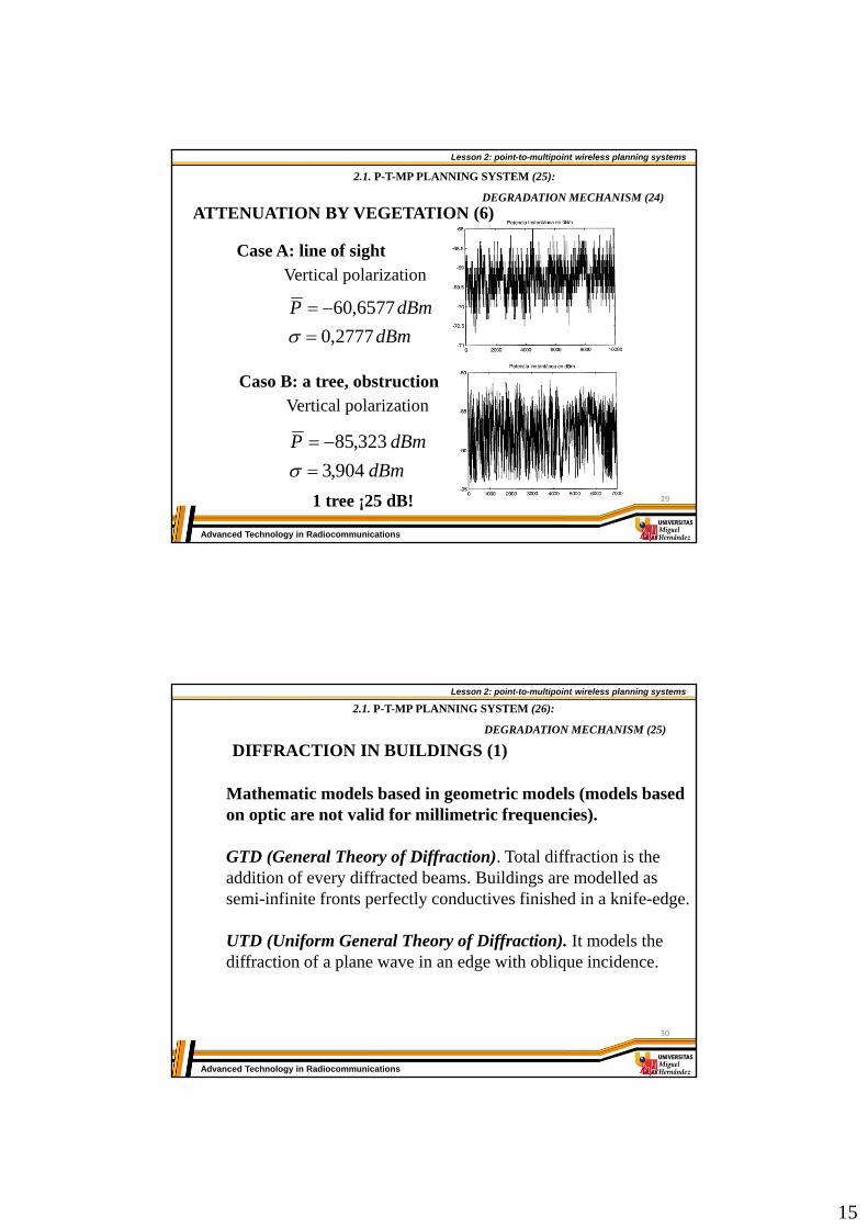
Vertical polarization
dBm
dBmP
2777,0
6577,60
Case A: line of sight
Vertical polarizationCaso B: a tree, obstruction
1 tree ¡25 dB!
dBm
dBmP
904,3
323,85
29
Lesson 2: point-to-multipoint wireless planning systems
Advanced Technology in Radiocommunications
2.1. P-T-MP PLANNING SYSTEM (26):
DEGRADATION MECHANISM (25)
DIFFRACTION IN BUILDINGS (1)
Mathematic models based in geometric models (models basedon optic are not valid for millimetric frequencies).
GTD (General Theory of Diffraction). Total diffraction is theaddition of every diffracted beams. Buildings are modelled as semi-infinite fronts perfectly conductives finished in a knife-edge.
UTD (Uniform General Theory of Diffraction). It models thediffraction of a plane wave in an edge with oblique incidence.
30

16
Lesson 2: point-to-multipoint wireless planning systems
Advanced Technology in Radiocommunications
2.1. P-T-MP PLANNING SYSTEM (27):
DEGRADATION MECHANISM (26)
DIFFRACTION IN BUILDINGS (2)
Tx RxR
21
21
dd
ddR
First Fresnel area R26=3,8 md = 5 km
31
Lesson 2: point-to-multipoint wireless planning systems
Advanced Technology in Radiocommunications
3. THEORETICAL CELLULAR PLANNING
3.1. Channeling.
3.2. Cellular shapes.
3.3. Frequency plan.
3.4. Cellular sizes.
- Power balance: link planning
- Quality if service
- User density
2.1. P-T-MP PLANNING SYSTEM (28):
32

17
Lesson 2: point-to-multipoint wireless planning systems
Advanced Technology in Radiocommunications
CHANNELING
Regulating organization assigns frequency plans to use in every service, defining:
Frequency band.
Division between channels and bandwidth per channel.
Channel assignment for downstream and upstream
This channeling is going to fix the basic work parameters torealize a correct system planning .
2.1. P-T-MP PLANNING SYSTEM (29):
THEORETICAL CELLULAR PLANNING (1)
33
Lesson 2: point-to-multipoint wireless planning systems
Advanced Technology in Radiocommunications
CELL SIZES
There are 3 main factors to establish the correct cell size.
1. LINK CALCULUS- Power balance- Fainting margin
2. QUALITY OF SERVICE- Carrier to noise ratio (C/N)- BER- ATM quality parameters
3. USER DENSITY
2.1. P-T-MP PLANNING SYSTEM (30):
THEORETICAL CELLULAR PLANNING (2)
34
18
Lesson 2: point-to-multipoint wireless planning systems
Advanced Technology in Radiocommunications
POWER BALANCE:LINK CALCULUS (1)
2.1. P-T-MP PLANNING SYSTEM (31):
THEORETICAL CELLULAR PLANNING (3)
Transmission equation:
Pr=Pt+Gt-AFS-A(d)+Gr
where A(d) is the addition of previously calculated attenuations
A(d)=(AATM+ALL+AN+ASNOW)xd
Received power must be bigger than the receiver sensitivity.
1. WE CONSIDER LINE OF SIGHT AVEG = ADIFF =0
2. VERTICAL POLARIZATION
35
Lesson 2: point-to-multipoint wireless planning systems
Advanced Technology in Radiocommunications
POWER BALANCE:LINK CALCULUS (2)
2.1. P-T-MP PLANNING SYSTEM (32):
THEORETICAL CELLULAR PLANNING (4)
Receiver sensitivity depends on the modulation(QPSK, 16QAM, 64QAM)
• QPSK receiver sensitivity (ETSI) 10 GHz 26 GHz
7 MHz -85 dBm -88 dBm14 MHz -82 dBm -85 dBm
Ptx(26)=+19 dBmPtx(10)=+20 dBm
If we suppose this Ptx, GT= 15 dBi, GR=35 dBi, we obtain
• Maximum cell size26 GHz 10 GHz
14 MHz 3.6 km 7,7 km7 MHz 3.2 km 9 km
MD: 6 dB/kmMD: 3 dB/km
36
19
Lesson 2: point-to-multipoint wireless planning systems
Advanced Technology in Radiocommunications
POWER BALANCE:LINK CALCULUS (3)
2.1. P-T-MP PLANNING SYSTEM (33):
THEORETICAL CELLULAR PLANNING (5)
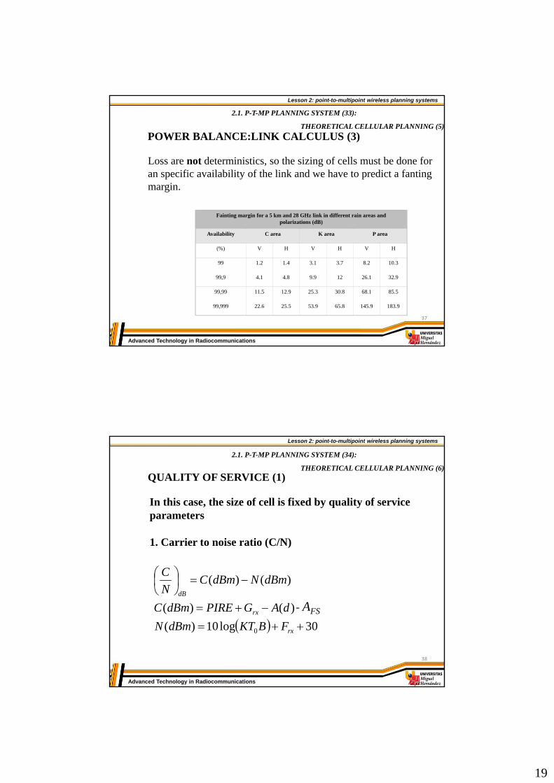
Loss are not deterministics, so the sizing of cells must be done foran specific availability of the link and we have to predict a fantingmargin.
Fainting margin for a 5 km and 28 GHz link in different rain areas and polarizations (dB)
Availability C area K area P area
(%) V H V H V H
99 1.2 1.4 3.1 3.7 8.2 10.3
99,9 4.1 4.8 9.9 12 26.1 32.9
99,99 11.5 12.9 25.3 30.8 68.1 85.5
99,999 22.6 25.5 53.9 65.8 145.9 183.9
37
Lesson 2: point-to-multipoint wireless planning systems
Advanced Technology in Radiocommunications
QUALITY OF SERVICE (1)
2.1. P-T-MP PLANNING SYSTEM (34):
THEORETICAL CELLULAR PLANNING (6)
In this case, the size of cell is fixed by quality of serviceparameters
1. Carrier to noise ratio (C/N)
30log10)(
)()(
)()(
0
rx
rx
dB
FBKTdBmN
dAGPIREdBmC
dBmNdBmCN
C
- AFS
38

20
Lesson 2: point-to-multipoint wireless planning systems
Advanced Technology in Radiocommunications
QUALITY OF SERVICE (1)
2.1. P-T-MP PLANNING SYSTEM (35):
THEORETICAL CELLULAR PLANNING (7)
2. Demoludator output BER
RX, FRXDEMOD
FEC
BER=10-6
ON
S
i
i
N
S
BER known limit0N
Eb
(it depends on the modulation)
Si
(knowing Ni)
ON
S
39
Lesson 2: point-to-multipoint wireless planning systems
Advanced Technology in Radiocommunications
Example: QPSK
o
bb N
EQP
2dB
N
E
o
b 10R
W
N
S
N
E
o
b
where W: bandwidth
R: information ratebs TT
W2
11
bTR
1
So:
2494.11log100
W
R
N
E
N
S b
i =0,75Finally:
KTBFN
SS RX
Oi log10
2.1. P-T-MP PLANNING SYSTEM (36):
THEORETICAL CELLULAR PLANNING (8)
40
21
Lesson 2: point-to-multipoint wireless planning systems
Advanced Technology in Radiocommunications
M-QAM
bbb kM
erfcM
kM
erfcMk
P 12
31
2
11
12
311
2
Where:M=2k, k: number of bits by symbolb= average SNR by bit
In this case, (adapted receiver)bS TkT
the relation between Q(x) and erfc(x) is the next:
22
1)(
22)(
xerfcxQ
xQxerfc
2.1. P-T-MP PLANNING SYSTEM (37):
THEORETICAL CELLULAR PLANNING (9)
41
Lesson 2: point-to-multipoint wireless planning systems
Advanced Technology in Radiocommunications
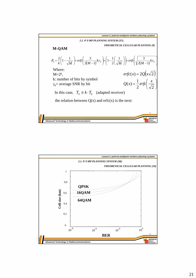
1
0
0,8
0,6
0,4
0,2
10-9
10-6
10-3
100
QPSK
16QAM
64QAM
BER
Cel
lsiz
e(k
m)
2.1. P-T-MP PLANNING SYSTEM (38):
THEORETICAL CELLULAR PLANNING (10)
42

22
Lesson 2: point-to-multipoint wireless planning systems
Advanced Technology in Radiocommunications
ATM QUALITY OF SERVICE PARAMETERS
It is possible to relate BER to own parameters from ATM networks like:
Cell loss ratio (CLR): relationship between cell loss and totalcell transmitted.
Cell error ratio (CER): relationship between cell error receivedand total cell transmitted.
ITU-T I.356 recommendation
2.1. P-T-MP PLANNING SYSTEM (39):
THEORETICAL CELLULAR PLANNING (11)
43
Lesson 2: point-to-multipoint wireless planning systems
Advanced Technology in Radiocommunications
USER DENSITY
If the user density is high, it is possible that you have todefine again the cell size.
- Restriction in avaliable bandwidth.- Restriction in WLL equipment.
- To use a more efficient modulation- To increase the number of used frequencies- To increase the cell sizing
If it is not possible To reduce the cell sizeTo increase the number of base stations
2.1. P-T-MP PLANNING SYSTEM (40):
THEORETICAL CELLULAR PLANNING (12)
44
23
Lesson 2: point-to-multipoint wireless planning systems
Advanced Technology in Radiocommunications
USER DENSITY
Main measurements are:- Number and building density (Na)- Expected penetration (%P).- Expected traffic by user (Tmax).
Number of cells=
max% TPNE a Number of needed channels
celdaofrecidoscanalesdeN
celdanecesarioscanalesdeN
/º
/º
N
n
n
N
BnA
NAP
0!/
!/
2.1. P-T-MP PLANNING SYSTEM (41):
THEORETICAL CELLULAR PLANNING (13)
45
Lesson 2: point-to-multipoint wireless planning systems
Advanced Technology in Radiocommunications
USER DENSITY
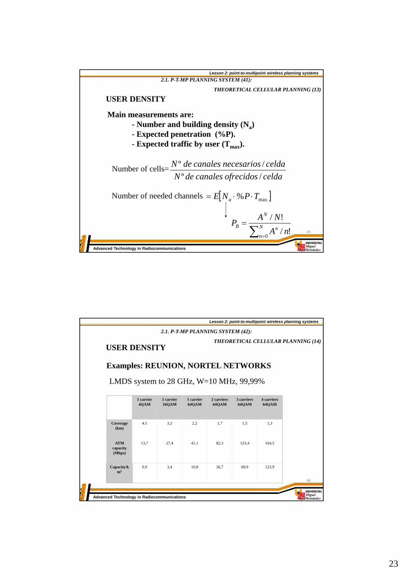
Examples: REUNION, NORTEL NETWORKS
1 carrier4QAM
1 carrier16QAM
1 carrier64QAM
2 carriers64QAM
3 carriers64QAM
4 carriers64QAM
Coverage(km)
4.5 3,2 2,2 1,7 1,5 1,3
ATM capacity(Mbps)
13,7 27,4 41,1 82,3 123,4 164,5
Capacity/km2
0,9 3,4 10,8 36,7 68,9 123,9
LMDS system to 28 GHz, W=10 MHz, 99,99%
2.1. P-T-MP PLANNING SYSTEM (42):
THEORETICAL CELLULAR PLANNING (14)
46

24
Lesson 2: point-to-multipoint wireless planning systems
Advanced Technology in Radiocommunications
4. STATISTIC MODEL
2.1. P-T-MP PLANNING SYSTEM (43):
STATISTIC MODEL (1)
Radio channel properties are changeable, so the descriptionsmust be statistics.
To do this, we must realice a measurement joint that will beprocessed to extract the parameter we need to model thechannel behavior.
From the statistics, we will realize a hypothesis test todeterminate what type of distribution models the channel weare evaluating.
47
Lesson 2: point-to-multipoint wireless planning systems
Advanced Technology in Radiocommunications
PROBABILITY DENSITY EQUATIONS
Long term fainting
We consider as a normal distribution
2
20
30
2
10ln
2
1exp
220
10ln)(
KPf
P
p
N
i i
N
i i
EN
EN
1
22
1
ln1
ln1
2.1. P-T-MP PLANNING SYSTEM (44):
STATISTIC MODEL (2)
48

25
Lesson 2: point-to-multipoint wireless planning systems
Advanced Technology in Radiocommunications
PROBABILITY DENSITY FUNCTIONS
Short term fainting
Several types of distribution: Nakagami-Rice. We use this whenwe have line of sight and exist one or many predominantcontributions.
12
2
0
2
20
30
02
220
30
2
10
30
1
2/
10
2
10exp
20
10ln10)(
i
i
PPP
p
i
xxI
K
CI
K
KC
KPf
2121
22
1
2
1
2
1
1
N
i i
N
i i
N
i i
EN
EN
EN
C
2.1. P-T-MP PLANNING SYSTEM (45):
STATISTIC MODEL (3)
49
Lesson 2: point-to-multipoint wireless planning systems
Advanced Technology in Radiocommunications
HYPOTHESIS TEST
It allows to decide what distribution models more easier thechannel behavior.
Two types:
Parametrics : SMIRNOV-KOLMOGOROV test. It calculatesthe difference between theorical distribution functions and empiric ones.
No parametrics: Pearson 2 test. It realizes the comparisonbetween theorical and empiric distribution functions along thesample space, avoiding punctual situations.
2.1. P-T-MP PLANNING SYSTEM (46):
STATISTIC MODEL (4)
50

26
Lesson 2: point-to-multipoint wireless planning systems
Advanced Technology in Radiocommunications
0 2 4 6 8 10 12 14 160
0.02
0.04
0.06
0.08
0.1
0.12
0.14
0.16
0.18
0.2
Potencia Normalizada (dBm)
Histograma Normalizado versus funciones de probabilidad
0 0.5 1 1.5 20
0.5
1
1.5
2
2.5
Potencia Normalizada (dBm)
Histograma Normalizado versus funciones de probabilidadEXAMPLE: vegetation model
Free space
Vegetation
NORMAL 0,1189 0,0450
RAYLEIGH 0,1382 0,1152
NAKAGAMI-RICE
0,2245 0,1449
NAKAGAMI 0,0915 0,0908
Normal
Rayleigh
Nakagami-Rice
Nakagami
2.1. P-T-MP PLANNING SYSTEM (47):
STATISTIC MODEL (5)
51
Lesson 2: point-to-multipoint wireless planning systems
Advanced Technology in Radiocommunications
WIRELESS POINT-TO-MULTIPOINT SYSTEMS
2.1. P-T-MP planning system2.2. P-T-MP components2.3. Manufacturers and distributors. 2.4. Market perspectives.2.5. Trials.2.6. Future trends.
52

27
Lesson 2: point-to-multipoint wireless planning systems
Advanced Technology in Radiocommunications
P-T-MP components1. INTRODUCTION
2. BASE STATION2.1. Block diagrams2.2. Radio equipment2.3. Interface with the main network
3. RADIO INTERFACE
4. USER EQUIPMENT4.1. Block diagram4.2. State of the art technology4.3. Receiver equipment 53
Lesson 2: point-to-multipoint wireless planning systems
Advanced Technology in Radiocommunications
2.2. P-T-MP COMPONENTS (1): INTRODUCTION
1. INTRODUCTION
Internetserver
Voice Switch Data Switch
ISP
GSM/CDMA/DECTMicro Cells
LAN, PABX
Microcells Feeder
ISDN-BA, POTS
SME and RTTBBS
TS
TS
TS
TS
TS
PMP system architecture
ATM/FRbackbone
54

28
Lesson 2: point-to-multipoint wireless planning systems
Advanced Technology in Radiocommunications
2.2. P-T-MP COMPONENTS (2): BASE STATION (1)
2.BASE STATION: BLOCK DIAGRAMS
Up to: 2 E1s/ BS-BU
Indoor
BS-BU
IF-MUX
LCTModemEthernet
Up to: 8 BS-BU or16 BS-BU/IF-MUX
Up to:3 Interfaces/BS-BU
ODU
V5.2
E1
PRA or
ISP
DataSwitch
VoiceSwitch
Different Interfaces
E1
ATMswitch
Different Interfaces
55
Lesson 2: point-to-multipoint wireless planning systems
Advanced Technology in Radiocommunications
2.2. P-T-MP COMPONENTS (3): BASE STATION (2)
RADIO EQUIPMENT: ODU
X
X
Tx/RxOL
Dip
lexo
r
Ant
LNA
Ref. Clock
CAG
Modem
Control PTXCAG
Dip
lexo
r
PA
56

29
Lesson 2: point-to-multipoint wireless planning systems
Advanced Technology in Radiocommunications
2.2. P-T-MP COMPONENTS (4): BASE STATION (3)
ANTENNAS
Omni-directionalTypical gain: 6-15 dBiBandwidth: 1 GHzPD: 20 dB“mushroom” antenna
Sectorial hornsTypical gain: 15-24 dBiSectors of 30, 45 and 90ºPD: 25 dB 57
Lesson 2: point-to-multipoint wireless planning systems
Advanced Technology in Radiocommunications
2.2. P-T-MP COMPONENTS (5): BASE STATION (4)
ANTENNAS
58

30
Lesson 2: point-to-multipoint wireless planning systems
Advanced Technology in Radiocommunications
2.2. P-T-MP COMPONENTS (6): BASE STATION (5)
STATE OF THE ART TECHNOLOGY: AMPLIFIERS
Power amplifiers (SSPA)
Low noise amplifiers(LNA)
G > 30 dBNF: 8dBP-1dB > 1 W (30 dBm) G > 25 dB
NF: 5 dB (4 GHz)P-1dB > 23 dBm 59
Lesson 2: point-to-multipoint wireless planning systems
Advanced Technology in Radiocommunications
2.2. P-T-MP COMPONENTS (7): BASE STATION (6)
STATE OF THE ART TECHNOLOGY: AMPLIFIERSPA
HPA
SwitchSwitch
P-1dB < 10 W (SSPA)P-1dB < 60 W (TWT)
60
31
Lesson 2: point-to-multipoint wireless planning systems
Advanced Technology in Radiocommunications
2.2. P-T-MP COMPONENTS (8): INTERFACE WITH THE MAIN NETWORK (1)
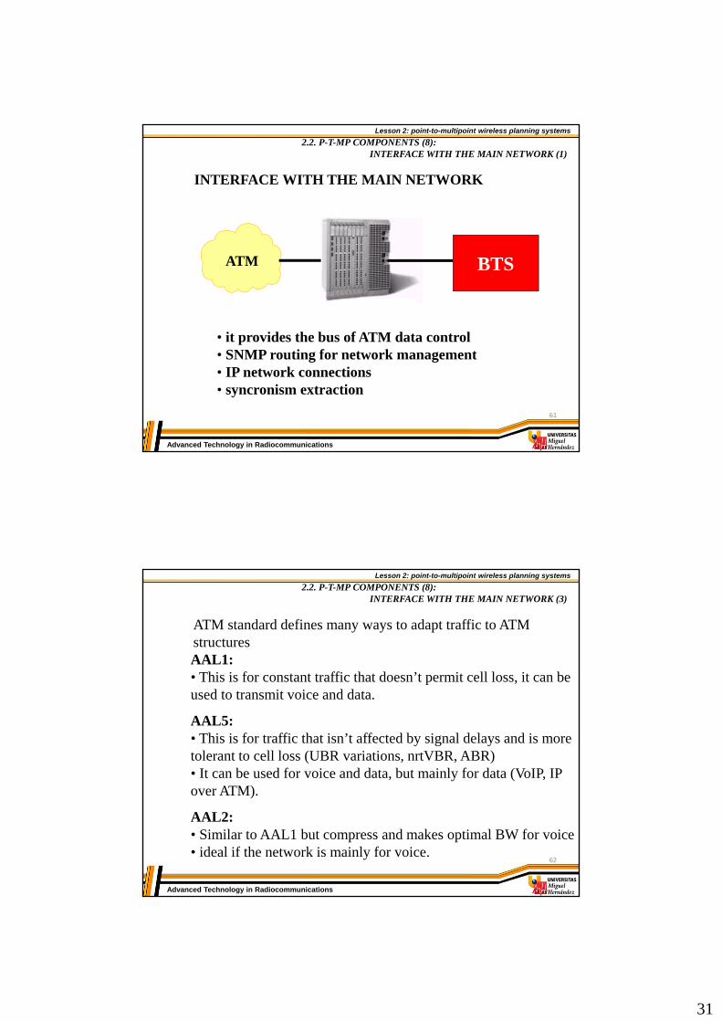
INTERFACE WITH THE MAIN NETWORK
BTSATM
• it provides the bus of ATM data control• SNMP routing for network management• IP network connections• syncronism extraction
61
Lesson 2: point-to-multipoint wireless planning systems
Advanced Technology in Radiocommunications
2.2. P-T-MP COMPONENTS (8): INTERFACE WITH THE MAIN NETWORK (3)
ATM standard defines many ways to adapt traffic to ATM structuresAAL1: • This is for constant traffic that doesn’t permit cell loss, it can beused to transmit voice and data.
AAL5:• This is for traffic that isn’t affected by signal delays and is more tolerant to cell loss (UBR variations, nrtVBR, ABR)• It can be used for voice and data, but mainly for data (VoIP, IP over ATM).
AAL2:• Similar to AAL1 but compress and makes optimal BW for voice• ideal if the network is mainly for voice.
62
32
Lesson 2: point-to-multipoint wireless planning systems
Advanced Technology in Radiocommunications
2.2. P-T-MP COMPONENTS (10): RADIO INTERFACE (1)
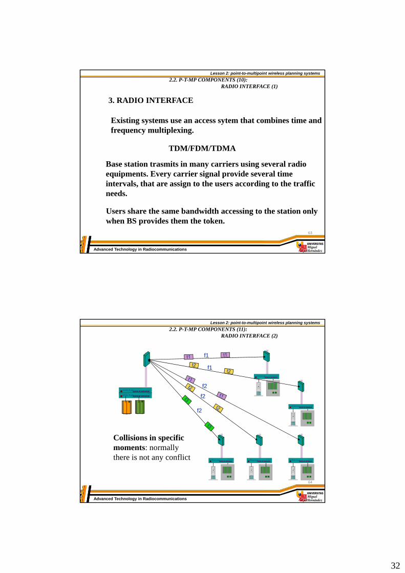
3. RADIO INTERFACE
Existing systems use an access sytem that combines time and frequency multiplexing.
TDM/FDM/TDMA
Base station trasmits in many carriers using several radio equipments. Every carrier signal provide several time intervals, that are assign to the users according to the trafficneeds.
Users share the same bandwidth accessing to the station onlywhen BS provides them the token.
63
Lesson 2: point-to-multipoint wireless planning systems
Advanced Technology in Radiocommunications
2.2. P-T-MP COMPONENTS (11): RADIO INTERFACE (2)
Public Switch
WALKair
WALKairWALKairWALKair
WALKair
f1
f1
f2
f2
f2
WALKair
WALKair
Public Switch
Collisions in specificmoments: normallythere is not any conflict
64

33
Lesson 2: point-to-multipoint wireless planning systems
Advanced Technology in Radiocommunications
2.2. P-T-MP COMPONENTS (12): RADIO INTERFACE (3)
T
F7 MHz
Uplink (10.5 and 26 GHz)
T
7 MHz
Downlink (10.5 and 26 GHz)
8 Mbit/s
FDD Distance:
- 100 MHz for 3.5GHz Band- 350 MHz for 10.5GHz Band- 1,008 MHz for 26GHz Band
Terminal Station 1
Terminal Station 2
Up to Terminal Station 16
~ ~Downlink (3.5 GHz)Uplink (3.5 GHz)
65
Lesson 2: point-to-multipoint wireless planning systems
Advanced Technology in Radiocommunications
2.2. P-T-MP COMPONENTS (13): USER EQUIPEMT (1)
Indoor
TS-BU
Up to: 2 E1s/TS-BU
LCT
Up to: 3 Interfaces/TS-BU
PABX
Frame Relay
ISDN PRI / E1 ISDN BRI
IP
V5.1 / E1 ISDN BRI
POTS
10BaseT
FR / V35/X.21
ONU
Different Interfaces
Router
4. USER EQUIPMENT: BLOCK DIAGRAM
ODU
66
34
Lesson 2: point-to-multipoint wireless planning systems
Advanced Technology in Radiocommunications
2.2. P-T-MP COMPONENTS (14): USER EQUIPMENT (2)
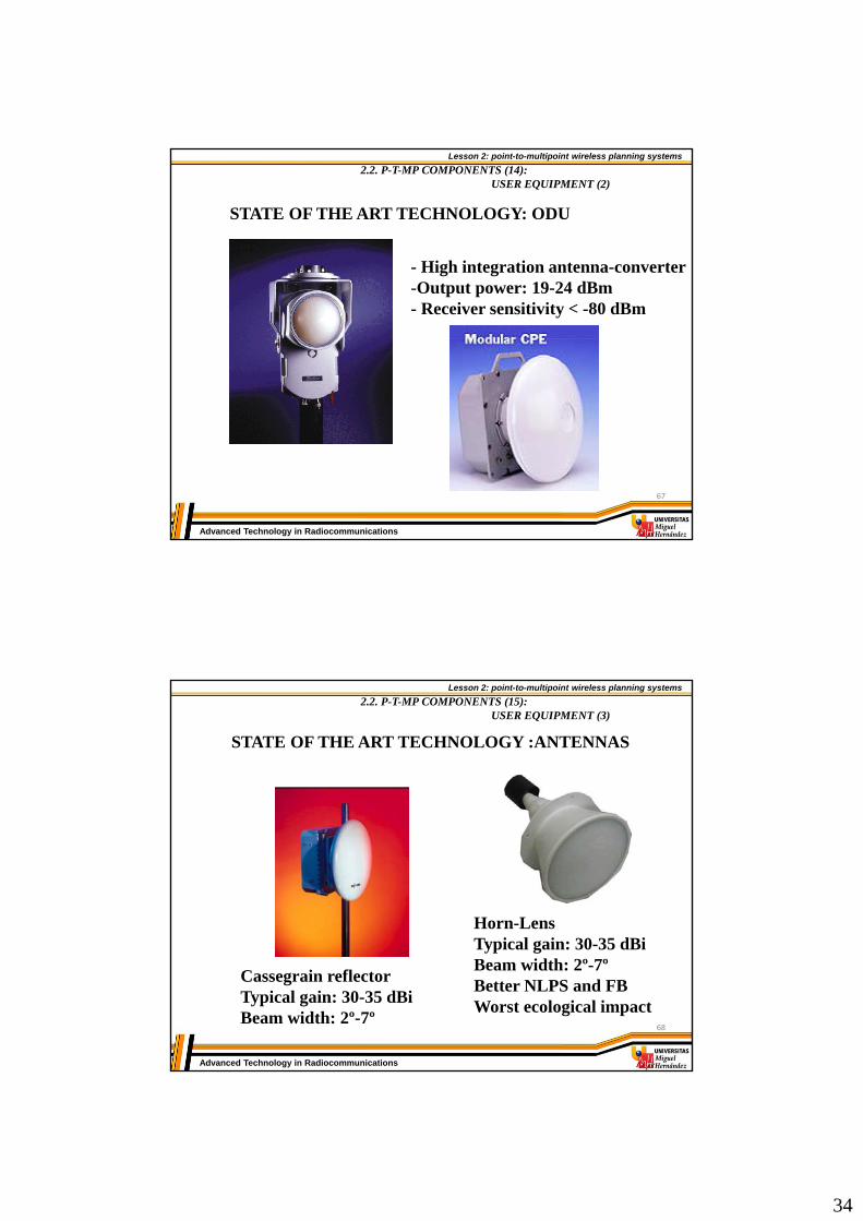
STATE OF THE ART TECHNOLOGY: ODU
- High integration antenna-converter-Output power: 19-24 dBm- Receiver sensitivity < -80 dBm
67
Lesson 2: point-to-multipoint wireless planning systems
Advanced Technology in Radiocommunications
2.2. P-T-MP COMPONENTS (15): USER EQUIPMENT (3)
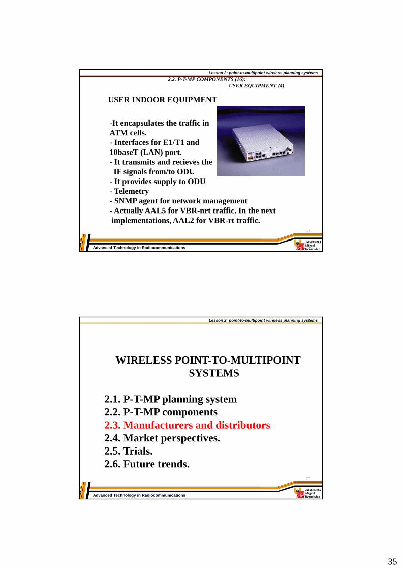
STATE OF THE ART TECHNOLOGY :ANTENNAS
Cassegrain reflectorTypical gain: 30-35 dBiBeam width: 2º-7º
Horn-LensTypical gain: 30-35 dBiBeam width: 2º-7ºBetter NLPS and FBWorst ecological impact
68
35
Lesson 2: point-to-multipoint wireless planning systems
Advanced Technology in Radiocommunications
2.2. P-T-MP COMPONENTS (16): USER EQUIPMENT (4)
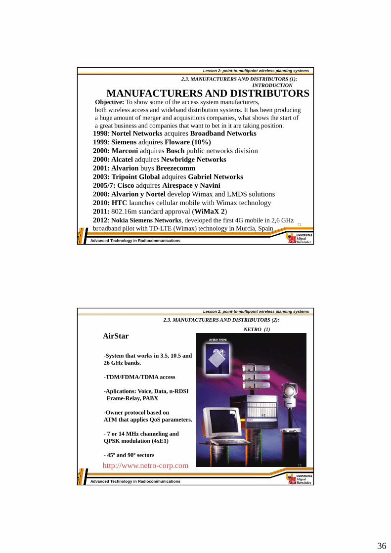
USER INDOOR EQUIPMENT
-It encapsulates the traffic inATM cells.- Interfaces for E1/T1 and 10baseT (LAN) port.- It transmits and recieves theIF signals from/to ODU
- It provides supply to ODU- Telemetry- SNMP agent for network management- Actually AAL5 for VBR-nrt traffic. In the nextimplementations, AAL2 for VBR-rt traffic.
69
Lesson 2: point-to-multipoint wireless planning systems
Advanced Technology in Radiocommunications
WIRELESS POINT-TO-MULTIPOINT SYSTEMS
2.1. P-T-MP planning system2.2. P-T-MP components2.3. Manufacturers and distributors2.4. Market perspectives.2.5. Trials.2.6. Future trends.
70
36
Lesson 2: point-to-multipoint wireless planning systems
Advanced Technology in Radiocommunications
2.3. MANUFACTURERS AND DISTRIBUTORS (1): INTRODUCTION
MANUFACTURERS AND DISTRIBUTORSObjective: To show some of the access system manufacturers,both wireless access and wideband distribution systems. It has been producing a huge amount of merger and acquisitions companies, what shows the start of a great business and companies that want to bet in it are taking position.
1998: Nortel Networks acquires Broadband Networks1999: Siemens adquires Floware (10%)2000: Marconi adquires Bosch public networks division2000: Alcatel adquires Newbridge Networks2001: Alvarion buys Breezecomm2003: Tripoint Global adquires Gabriel Networks2005/7: Cisco adquires Airespace y Navini2008: Alvarion y Nortel develop Wimax and LMDS solutions2010: HTC launches cellular mobile with Wimax technology2011: 802.16m standard approval (WiMaX 2)2012: Nokia Siemens Networks, developed the first 4G mobile in 2,6 GHzbroadband pilot with TD-LTE (Wimax) technology in Murcia, Spain
71
Lesson 2: point-to-multipoint wireless planning systems
Advanced Technology in Radiocommunications
2.3. MANUFACTURERS AND DISTRIBUTORS (2):
NETRO (1)
http://www.netro-corp.com
AirStar
-System that works in 3.5, 10.5 and 26 GHz bands.
-TDM/FDMA/TDMA access
-Aplications: Voice, Data, n-RDSIFrame-Relay, PABX
-Owner protocol based onATM that applies QoS parameters.
- 7 or 14 MHz channeling andQPSK modulation (4xE1)
- 45º and 90º sectors
72

37
Lesson 2: point-to-multipoint wireless planning systems
Advanced Technology in Radiocommunications
2.3. MANUFACTURERS AND DISTRIBUTORS (3):
NETRO (2)
• Coverage: 26 GHz 4 km (99,999%) 7 km (99,99%)10 GHz 16,2 km (99,999%) 27 km (99,99%)
• Huge amount of installed networks tested technology
• Synchronism are fixed by ATM. Base station transmits themodulated clock and users connect to it. It’s essential because of the access protocol (CellMac). System has very stable backupclocks just in case the network losts the connection.
73
Lesson 2: point-to-multipoint wireless planning systems
Advanced Technology in Radiocommunications
2.3. MANUFACTURERS AND DISTRIBUTORS (4):
ALVARION (1)
http://www.alvarion.com
BreezeAccess VL
- Frequencies: 5.725 - 5.850 GHz, 5.47 - 5.725 GHz, 5.15 - 5.35 GHz, 4.9 - 5.1 GHz
- TDD access
- Distance between channels 20 MHz
- Frequency resolution 10 MHz
- Output power: -10 dBm to 21 dBm (BS) -10 dBm to 21 dBm (TU)
-90º, 120º and 360º sectors
-LOS and NLOS
P-T-MP equipment
74

38
Lesson 2: point-to-multipoint wireless planning systems
Advanced Technology in Radiocommunications
2.3. MANUFACTURERS AND DISTRIBUTORS (5):
ALVARION (2)
BreezeAccess VL
Sensitivity
(dBm)
-89 -88 -86 -84 -81 -77 -73 -71
Modulationlevel
1 2 3 4 5 6 7 8
- Modulation:OFDM (BPSK, QPSK, 16QAM, 64 QAM)
- Network management:SNMP agent BreezeAccess owner equipment
- Gains of the antennas:16 dBi (90º), 15 dBi (120º), 8 dBi (360º) 75
Lesson 2: point-to-multipoint wireless planning systems
Advanced Technology in Radiocommunications
2.3. MANUFACTURERS AND DISTRIBUTORS (6):
ALVARION (3)
BreezeAccess LB
- Frequencies: 5.725 - 5.850 GHz, 5.47 - 5.725 GHz, 5.15 - 5.35 GHz, 4.9 - 5.1 GHz
- Power transmission: 20 dBm
- Gain 28 dBi
- 4,5º beam width antennas
- Rate transmission: 36-72 Mbps
- LOS and NLOS P-T-P equipment
76

39
Lesson 2: point-to-multipoint wireless planning systems
Advanced Technology in Radiocommunications
2.3. MANUFACTURERS AND DISTRIBUTORS (7):
P/COM
AirPro• Coverage until 10 km• Work frequencies: all allowedbands from 10 to 38 GHz• Several modulation types: QPSK, 16 y 64QAM• Capacity until 85E1/sector, 24 sectors/BS, multi-service• TDM/FDMA/TDMA access• SNMP over HP Openview
77
Lesson 2: point-to-multipoint wireless planning systems
Advanced Technology in Radiocommunications
2.3. MANUFACTURERS AND DISTRIBUTORS (8):
NORTEL NETWORKS
NORTEL NETWORKS: REUNION
• Coverage until 35 km• Work frequencies: all allowed bands from 2 to 42 GHz• Several modulation types: QPSK, 16 y 64QAM• Capacity: STM-1/sector, 16 sectors/BS• TDM/FDMA/TDMA access• SNMP over owner platform• User equipments allow until 4E1+1 10Base-T
78
40
Lesson 2: point-to-multipoint wireless planning systems
Advanced Technology in Radiocommunications
2.3. MANUFACTURERS AND DISTRIBUTORS (6):
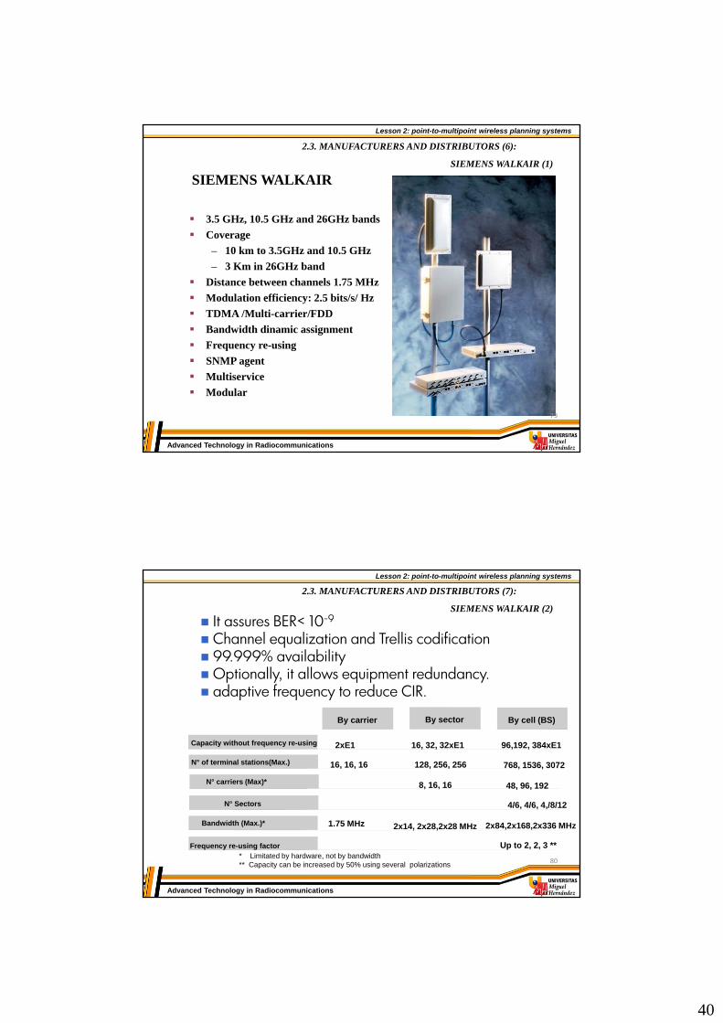
SIEMENS WALKAIR (1)
3.5 GHz, 10.5 GHz and 26GHz bands
Coverage
– 10 km to 3.5GHz and 10.5 GHz
– 3 Km in 26GHz band
Distance between channels 1.75 MHz
Modulation efficiency: 2.5 bits/s/ Hz
TDMA /Multi-carrier/FDD
Bandwidth dinamic assignment
Frequency re-using
SNMP agent
Multiservice
Modular
SIEMENS WALKAIR
79
Lesson 2: point-to-multipoint wireless planning systems
Advanced Technology in Radiocommunications
2.3. MANUFACTURERS AND DISTRIBUTORS (7):
SIEMENS WALKAIR (2)
It assures BER< 10-9
Channel equalization and Trellis codification 99.999% availability Optionally, it allows equipment redundancy. adaptive frequency to reduce CIR.
N° Sectors 4/6, 4/6, 4,/8/12
N° of terminal stations(Max.) 16, 16, 16
1.75 MHz 2x14, 2x28,2x28 MHz 2x84,2x168,2x336 MHzBandwidth (Max.)*
8, 16, 16N° carriers (Max)*
Up to 2, 2, 3 **Frequency re-using factor
By cell (BS)By sectorBy carrier
2xE1 16, 32, 32xE1 96,192, 384xE1Capacity without frequency re-using
128, 256, 256 768, 1536, 3072
48, 96, 192
* Limitated by hardware, not by bandwidth ** Capacity can be increased by 50% using several polarizations 80

41
Lesson 2: point-to-multipoint wireless planning systems
Advanced Technology in Radiocommunications
2.3. MANUFACTURERS AND DISTRIBUTORS (8):
MOTOROLA(1)
P-T-MP equipment
- Frequencies:5.47 - 5.725 GHz
- Gain 7 dBi
- Rate transmission: 20 Mbps
- LOS and NLOS
-Allowed protocols: IPV4, UDP, TCP, ICMP, Telnet, HTTP, FTP, SNMP
-Network management: HTTP, FTP, SNMP version 2c
Advantage SMPIRE: Adjustable
Advantage APPIRE: 30 dBm
Base station
User
81
Lesson 2: point-to-multipoint wireless planning systems
Advanced Technology in Radiocommunications
2.3. MANUFACTURERS AND DISTRIBUTORS (9):
MOTOROLA(2)
P-T-P equipment
PTP 58300 & PTP 54300
- Frequencies: 5.725 GHz–5.875 GHz5.470 GHz–5.725 GHz
-Channel bandwidth: 15 MHz
- Channel selection: Dynamic Frequency Selection (i-DFS) or manual selection
- Antenna: 9º beam width and 23 dBi of gain
- Dynamic modulation, between BPSK and 64QAM
- Security and encryption: owner model and optional 128 and 256 AES
82
42
Lesson 2: point-to-multipoint wireless planning systems
Advanced Technology in Radiocommunications
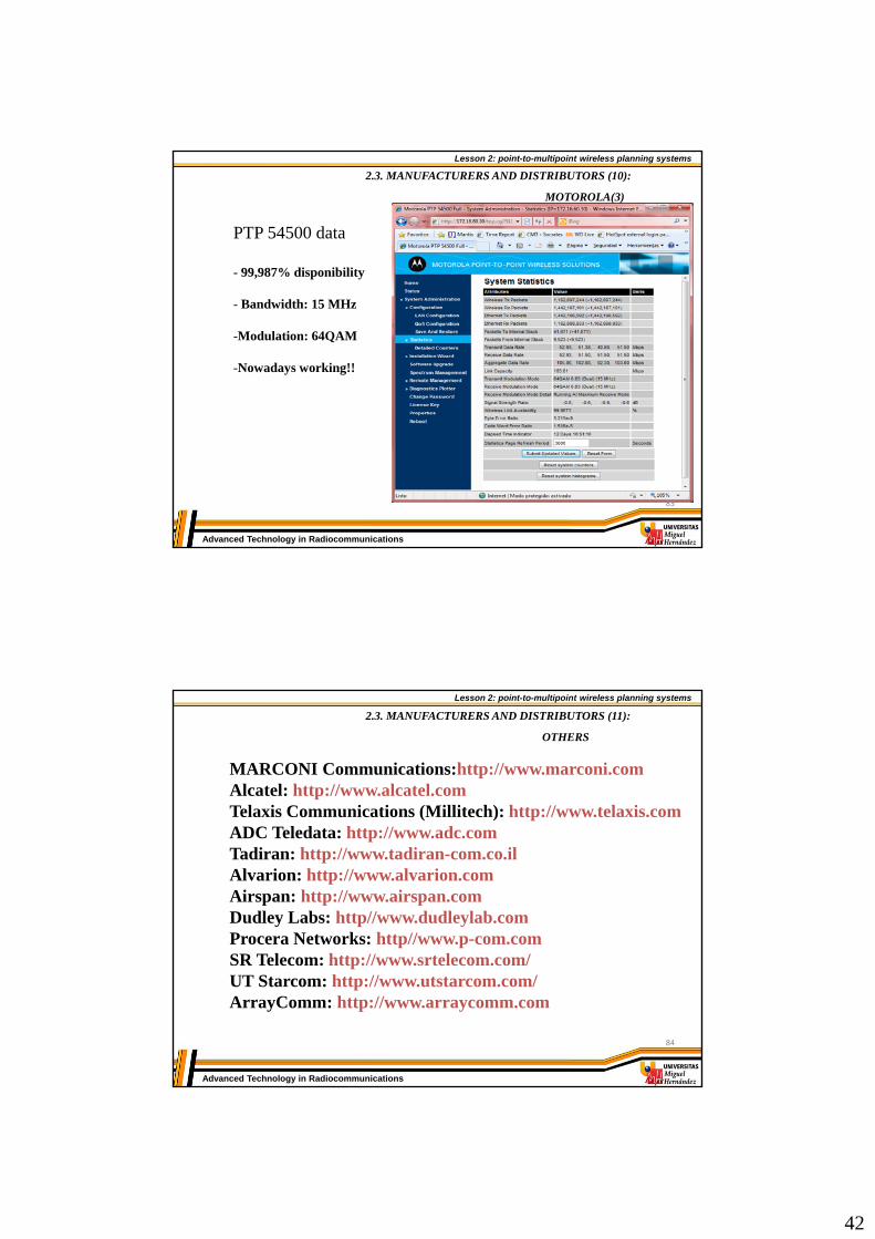
PTP 54500 data
- 99,987% disponibility
- Bandwidth: 15 MHz
-Modulation: 64QAM
-Nowadays working!!
2.3. MANUFACTURERS AND DISTRIBUTORS (10):
MOTOROLA(3)
83
Lesson 2: point-to-multipoint wireless planning systems
Advanced Technology in Radiocommunications
2.3. MANUFACTURERS AND DISTRIBUTORS (11):
OTHERS
MARCONI Communications:http://www.marconi.comAlcatel: http://www.alcatel.comTelaxis Communications (Millitech): http://www.telaxis.comADC Teledata: http://www.adc.comTadiran: http://www.tadiran-com.co.ilAlvarion: http://www.alvarion.comAirspan: http://www.airspan.comDudley Labs: http//www.dudleylab.comProcera Networks: http//www.p-com.comSR Telecom: http://www.srtelecom.com/UT Starcom: http://www.utstarcom.com/ArrayComm: http://www.arraycomm.com
84

43
Lesson 2: point-to-multipoint wireless planning systems
Advanced Technology in Radiocommunications
2.3. MANUFACTURERS AND DISTRIBUTORS (12):
INTEGRATION SYSTEMS (1)
The problem of WLL turn-key system manufacturers is thefact that the technologies are mostly owner technologies, so the operator is related to manufacturers.
INTEGRATION SYSTEMS
Sometimes, it can be interesting to break this chains and touse an integration system. Manufacturers produce and assemble sub-systems(amplifiers, oscillators, filters,….) thatcreate radio unities of WLL systems: ODU’s.
For example: repeaters85
Lesson 2: point-to-multipoint wireless planning systems
Advanced Technology in Radiocommunications
2.3. MANUFACTURERS AND DISTRIBUTORS (13):
INTEGRATION SYSTEMS (2)
MMCOMM Inc: http://www.mmcom-inc.comM/ACOM: http://www.macom.comREMEC: http://www.remec.comDBS NARDA: http://www.nardamicrowave.comMITEQ: http://www.miteq.comQUINSTAR: http://www.quinstar.comSPACEK LABS: http://www.spaceklabs.comFARRAN: http://www.farran.comANDREW: http://www.andrew.comTRIPOINT GLOBAL: http://www.tripointglobal.comDORADO: http://www.dorado-intl.comFLANN: http://www.flann.com/
86

44
Lesson 2: point-to-multipoint wireless planning systems
Advanced Technology in Radiocommunications
WIRELESS POINT-TO-MULTIPOINT SYSTEMS
2.1. P-T-MP planning system2.2. P-T-MP components2.3. Manufacturers and distributors. 2.4. Market perspectives.2.5. Trials.2.6. Future trends.
87
Lesson 2: point-to-multipoint wireless planning systems
Advanced Technology in Radiocommunications
MARKET ISSUES
1. INTRODUCTION
2. EVOLUTION OF THE NUMBER OF USERS
3. COMPARATIVE CABLE-WLL
88

45
Lesson 2: point-to-multipoint wireless planning systems
Advanced Technology in Radiocommunications
2.4. MARKET ISSUES (1):
INTRODUCTION (1)
INTRODUCTION
According to analysts, WLL system development has juststarting
In markets where is allowed, new operators offer, basically, twotypes of services.
• Internet connections (Wireless ISP)• Distribution of video, voice and data systems (LMDS)On other hand, cellular mobile operators have found in wirelessaccess systems (FWA) an opportunity to access to fixed segment.
89
Lesson 2: point-to-multipoint wireless planning systems
Advanced Technology in Radiocommunications
2.4. MARKET ISSUES (2):
EVOLUTION OF NUMBER OF USERS
EVOLUTION OF THE NUMBER OF USERS
According to analyst, the demand growth in WLL systems willbe dominated by data services (medium and high capacity and the video distribution ones).
90

46
Lesson 2: point-to-multipoint wireless planning systems
Advanced Technology in Radiocommunications
2.4. MARKET ISSUES (3):
COMPARATIVE CABLE-WLL
COMPARATIVE CABLE-WLL
10000
8000
6000
4000
2000
0
5% 10% 15% 20% 25%
Cos
t/co
stu
mer
(US
$)
% of penetration
High densityMedium densityLow density
¡¡M
AIN
TE
NA
NC
E C
OS
TS
!!
91
Lesson 2: point-to-multipoint wireless planning systems
Advanced Technology in Radiocommunications
WIRELESS POINT-TO-MULTIPOINT SYSTEMS
2.1. P-T-MP planning system2.2. P-T-MP components2.3. Manufacturers and distributors. 2.4. Market perspectives.2.5. Trials2.6. Future trends.
92

47
Lesson 2: point-to-multipoint wireless planning systems
Advanced Technology in Radiocommunications
2.5. TRIALS (1):
TRIALSCOLLSEROLA
High capacity internet connection (2 Mbps)digital TV broadcasting
Objetives:
•To save trips to central assistances : tele-rehabilitation•Distance learning networks: tele-education
Stage 2: 34 Mbps links (working) 93
Lesson 2: point-to-multipoint wireless planning systems
Advanced Technology in Radiocommunications
UPV-FRG
75/50LO
HI A6 75/50
VCO
A1650/75
A3650/75
S/C
FPB UPC
UPCDC
DCUpstream
Downstream
CATV backbone
S/C
700 MHz
20 MHz
20 MHz
800 MHz
Upstream
Downstream
20 MHz
800MHz
NMAPS
S/C
FTPClient
FTPClient
CM1
CM2
FTPServer
NMAPS
VLAN-2Ethernet HUB
800 MHz
28 GHz
• bidirectional transmissions using Com21 cable-modems• 2 Mbps, 64 QAM
2.5. TRIALS (2):
94

48
Lesson 2: point-to-multipoint wireless planning systems
Advanced Technology in Radiocommunications
CRABS
ACTS Project 215Cellular Radio Access for Broadband Services
• They propose architecture and LMDS service systems for 40 GHz besides of planification and medium access (ReportD2P1B).
• trials in Norway, Greece, Italy and UK. DVB video distributionand Internet access (Report D4P4).
• Deliverable D1P2: level interest and user satisfaction tests.
2.5. TRIALS (3):
95
Lesson 2: point-to-multipoint wireless planning systems
Advanced Technology in Radiocommunications
WIRELESS POINT-TO-MULTIPOINT SYSTEMS
2.1. P-T-MP planning system2.2. P-T-MP components2.3. Manufacturers and distributors. 2.4. Market perspectives.2.5. Trials.2.6. Future trends
96
49
Lesson 2: point-to-multipoint wireless planning systems
Advanced Technology in Radiocommunications
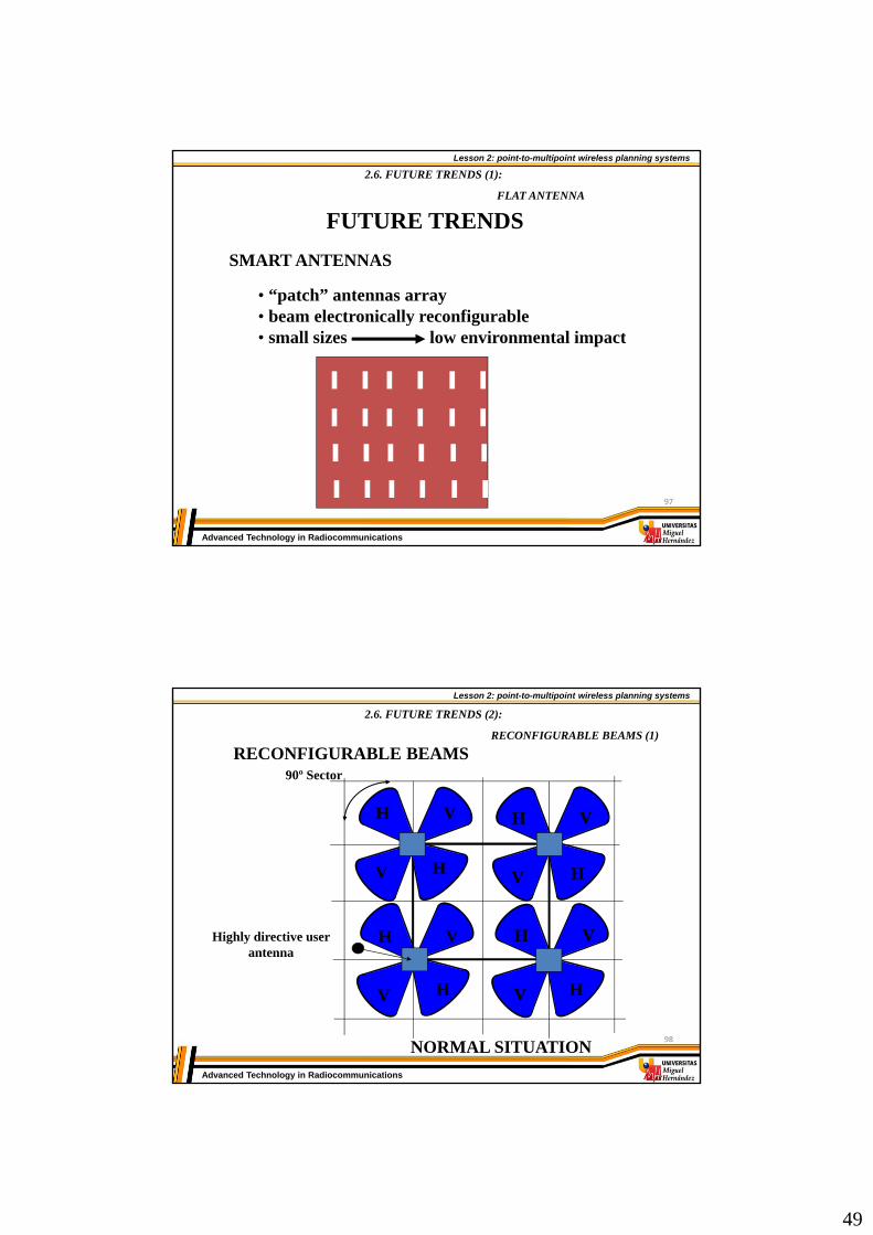
2.6. FUTURE TRENDS (1):
FLAT ANTENNA
SMART ANTENNAS
• “patch” antennas array• beam electronically reconfigurable• small sizes low environmental impact
FUTURE TRENDS
97
Lesson 2: point-to-multipoint wireless planning systems
Advanced Technology in Radiocommunications
2.6. FUTURE TRENDS (2):
RECONFIGURABLE BEAMS (1)
RECONFIGURABLE BEAMS
H
H
V
V
H
H
V
V
H
H
V
V
H
H
V
V
NORMAL SITUATION
90º Sector
Highly directive userantenna
98

50
Lesson 2: point-to-multipoint wireless planning systems
Advanced Technology in Radiocommunications
2.6. FUTURE TRENDS (3):
RECONFIGURABLE BEAMS (2)RECONFIGURABLE BEAMS
H H
V
V
H
H
VV
H
V
V
H
H
V
V
V
H
HDedicated beamV
Polarizationdiversity
Interferences source
ANOMALOUS SITUATION
BEAM STEERING
99
Lesson 2: point-to-multipoint wireless planning systems
Advanced Technology in Radiocommunications
2.6. FUTURE TRENDS (4):
RECONFIGURABLE BEAMS (3)
OPTIC SHAPED OF BEAMS
MZ-EOM
1
2
N
WDM
N
1
2
RF
Con
trol
del
d
iagr
ama
1
2
N
Variable delay according towavelength
Wide band diffraction
network
100

51
Lesson 2: point-to-multipoint wireless planning systems
Advanced Technology in Radiocommunications
2.6. FUTURE TRENDS (5):
OPTICAL FIBER PASIVE DISTRIBUTION NETWORK
OPTICAL FIBER PASIVE DISTRIBUTION NETWORK
se t -t o p bo x
se t -t o p bo x
se t -t o p bo xs e t - to p b o x
s e t - to p b o x
se t -to p b o x
S P L IT TE R
S P L IT TE R
S P L IT TE R
C A B L E
LMDS receiver
Satellitereceiver
TX/RXBidirectional
To set distribution coaxial networks “in-building”
101
Lesson 2: point-to-multipoint wireless planning systems
Advanced Technology in Radiocommunications
2.6. FUTURE TRENDS (6):
OPTICAL FIBER PASIVE DISTRIBUTION NETWORK
opticRX
opticTX
Optic coupler
Optic coupler
Optical fiber
LASER1300 nmdownlink
LED1300 nmuplink
radio TX/RX
OpticRX
OpticTX
WDM techniques, low cost return channel
102


![Point-to-Multipoint and Multipoint-to-Multipoint · PDF filedefined by IEEE 802.1Qay [2] is representative carrier Ethernet . Abstract — We have implemented point-to-multipoint (PtMP)](https://img.pdfslide.us/doc/110x75/5a75c0147f8b9a4b538cb6cd/point-to-multipoint-and-multipoint-to-multipoint-defined-by-ieee-8021qay.jpg)