Embed Size (px)
Citation preview
Ceramics International 30 (2004) 2251–2257
Point load-induced fracture behavior in zirconiaplasma spray coating
Yoshio Akimunea,∗, Kazuo Matsuoa, Satoshi Sodeokaa,Tatsuo Sugiyamaa, Satoshi Shimizub
a National Institute of Advanced Industrial Science and Technology, 1-1-1 Umezono, Tsukuba, Ibaraki-Prefecture 305-8568, Japanb Nissan Arc, Ltd, 1, Natsushima-cho, Yokosuka, Kanagawa-Prefecture 237-0061, Japan
Received 30 May 2003; received in revised form 3 November 2003; accepted 30 December 2003Available online 17 April 2004
Abstract
Heat-resistant coatings prepared by two different spraying methods: atmospheric pressure plasma spraying (APS) and high-pressure plasmaspraying (HPPS), were tested using tungsten carbide indenters of different diameters, for the purpose of proposing the best suited methodof indentation testing. It was found that with the APS method, the indentation load–depth curve gave the indentation depth and the residualdepth smaller than and the yield stress greater than those with the HPPS. On the basis of fracture morphology in the cross-section, it has beenconjectured that the APS coating has greater elastic modulus than the HPPS coating, and exhibits high strength exceeding debonding forcebetween bond coat and top coat.© 2004 Elsevier Ltd and Techna S.r.l. All rights reserved.
Keywords: Indentation; Plasma spray coating; Hertz cone crack; Elastic–plastic response debonding
1. Objective
The heat-resistant coating technology is used for the pro-tective surface coating of the metal blades in the generatorgas turbine, which is the mainstay equipment of the ther-mal power generation. As the fuel species shift to heavy oiland coal in the days ahead, it is of concern that problems ofcombustion residuals and utilization under corrosive atmo-sphere may arise. The use of turbine blades with protectivecoating involves debonding of coating triggered by pointload-induced fractures through bombardments with combus-tion residuals. This may lead to substrate damages and mustbe resolved immediately.
For the evaluation of mechanical properties of ceramicprotective coating for the turbine blade, a number of reportsare available in regard to damage morphology evaluationbased on the load–stress curves of coating induced by pointload impact, such as Pajares et al.[1,2], Wuttiphan et al.[3], Swain and Mencık [4], Lee et al.[5]. These studies arederived from the theoretical analysis works by Hertz[6],
∗ Corresponding author.E-mail address: [email protected] (Y. Akimune).
Timoshenko and Goodier[7], and Johnson[8]. Papers onceramics damage are reviewed by Lawn[9].
The present study aims at proposing an optimum methodfor indentation tests to detect damages in heat-resistant coat-ing prepared by either of two spray techniques: atmosphericplasma spraying (APS) and high-pressure plasma spraying(HPPS). In the experiment, specimens were prepared by cov-ering Inconel 600 substrate with a bond coat and either oftwo zirconia spray coats, and indented with spherical inden-ters through a quasi-static method, subsequently examiningthe fracture and debond behaviors of the coats.
2. Experimental methods
2.1. Sprayed specimen
The specimen consisted of a substrate of Inconel 600, aspray coat of zirconia stabilized with 8 mass% (METECO204NS-G) and an intermediate bond coat of NiCoCrAlY(AMDRY-1). The substrate surface was polished with #70alumina to make the roughness to Ra= 5�m, and cleanedby reverse sputtering at 1073 K immediately before adding
0272-8842/$30.00 © 2004 Elsevier Ltd and Techna S.r.l. All rights reserved.doi:10.1016/j.ceramint.2003.12.008
2252 Y. Akimune et al. / Ceramics International 30 (2004) 2251–2257
Nomenclature
a indent impression radiusEs Young’s modulus of substrateEi Young’s modulus of indenterh indentation depthhy impression depthKe composite Young’s modulusP pressurePm indentation pressurep0 contact pressurePy yield stressR indenter diameterνs Young’s modulus of substrateνi Young’s modulus of indenter
bond coat. The substrate temperature was not measured af-ter that. The top coat was provided either by APS or byHPPS using 200 kPa Argon to make up a zirconia coat of200�m thickness. Spray parameters are listed inTable 1.The construction of plasma spray system is described in theliterature[10].
2.2. Testing methods
2.2.1. Microindentation test [11]The coated film was indented with a spherical indenter of
tungsten carbide (WC) at a specified speed (v = 1.67�m/s),with load (P) and impression depth (h) measured after hav-ing unloaded. With an indenting equipment consisting ofan indenter mounted on a strength testing machine (Instron#5867) the impression depth and the load–depth curve wererecorded at the room temperature, 0.05 mm/min crossheadspeed and 1 kN load (Fig. 1). Then, the data were con-
Table 1Plasma spraying condition
Bond coat Top coat
Atmospheric plasma spraying High-pressure plasma spraying
Materials NiCoCrAlY (AMDRY365-1) 8 mass% Y2O3 stabilizedZrO2 (METCO204NS-G)
8 mass% Y2O3 stabilizedZrO2 (METCO204NS-G)
Particle size 45–53�m 11–106�m 11–106�mSubstrate roughness Ra: 5�mCoating temperature 1073 K pre-heating 1073 K pre-heating 1073 K pre-heatingType of plasma torch Sulzer Meteco F4VB Sulzer Meteco F4VB Sulzer Meteco F4VBAtmosphere and flow rate Ar: 50 l/min Air Ar: 50 l/minAnode nozzle internal diameter 7 mm 7 mm 7 mmType of injection Internal Internal InternalInjector internal diameter 3.0 mm 1.5 mm 1.5 mmPressure 10 kPa Air 200 kPaSpray distance 300 mm 100 mm 10 mmGas flow Ar: 50 l/min; H2: 9 l/min Ar: 42 l/min; H2: 10 l/min Ar: 50 l/min; H2: 5 l/min;
He: 10 l/minPowder feed 0.025 kg/min 0.0048 kg/min 0.0052 kg/min
verted into the load–stress curve by using a theoretical equa-tion shown in the later part,Pm∝(h/R)0.5 to calculate theyield stress. Loading and unloading were carried out at thesame speed, and the depth–unload curve was measured threetimes. The maximum load was set to 1 kN. At the peakload, the crosshead of the testing machine was reversed,with the load retained for 1 s or so, owing to the mechanicalplay.
2.2.2. Preparation of specimenThe test-piece was prepared by cutting into approximately
15 mm× 15 mm× 3 mm plate and the sprayed surface waspolished to Ra= 0.2�m with abrasive agent (Buehler, col-loidal silica 0.06�m). The residual thickness of spray layerwas 95 and 85�m for APS and HPPS, respectively, whilethe bond coat was about 115�m in thickness.
2.2.3. Indent impression observationAfter the indentation test, the impression on the surface
was observed by the optical microscopy. The specimen wascut in the vicinity of the indent impression, embedded inepoxy resin with the sectional face upward, and polished tothe center of the impression using abrasive agent (Buehler,colloidal silica 0.06�m), to be observed under an opticalmicroscope in the bright field.
2.2.4. Analysis of static indentation behavior
2.2.4.1. Load calculation [6–8]. The pressure caused bythe indentation of a blunt indenter is given by the equation:
P
πa2=
(3E
4πk
) ( a
R
)= p0 (1)
which was derived from Hertz’s theory of elasticity,a3 =4kPR/3E, wherea is the indent impression radius,R is theindenter diameter, andk = 9/16[(1− ν2
s)+ (1− ν2i )Es/Ei ],
Y. Akimune et al. / Ceramics International 30 (2004) 2251–2257 2253
Fig. 1. An overall view of quasi-static indentation testing system.
where Es and Ei are Young’s modulus, andνs and νiare Poisson’s ratio, of substrate and indenter, respec-tively.
If the impression depthh is used, the relation is writtenasR2 = a2 + (R − h)2, which may be approximated with(a/R)2 = h/R, if R � h. The relationship ofp0 to (h/R)0.5
will be plotted subsequently.
2.2.4.2. Composite Young’s modulus. The compositeYoung’s modulus was calculated from expressions (2) and(3) with slope (Ke) and yielding point (yield stress:Py andimpression depth:hy), using a graph plotting indent loadon the ordinate and 3/2 power of impression depth on theabscissa.
P = Keh3/2 (relation of pressure to impression depth)
Ke = 4
3(RE∗)1/2 (composite Young’s modulus) (2)
1
E∗ = (1 − ν2s)
Es+ (1 − ν2
i )
Ei(3)
Pm = Py
πRh(4)
whereEi andEs are the Young’s modulus of indenter (WC:534 GPa) and substrate (Inconel: 200 GPa),νi and νs arethe Poisson’s ratio of indenter (WC: 0.28) and substrate(Inconel: 0.3),Pm is the indentation pressure, andPy is theyield stress.
3. Results and discussion
3.1. Quasi-static indentation test
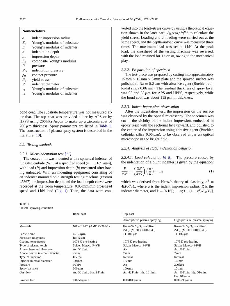
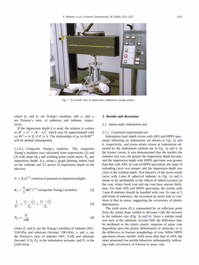
3.1.1. Continued load/unload testIndentation load–depth curves with APS and HPPS spec-
imens following an indentation are shown inFig. 2a andb, respectively, and stress–strain curves at indentation ob-tained by the indentation method are inFig. 3a and b. Inthe former curves, it was demonstrated that the smaller theindenter size was, the greater the impression depth became,and the impression depth with HPPS specimen was greaterthan that with APS. In case of HPPS specimens, the slope ofunloading curve was steeper, and the impression depth wasclose to the residual depth. Non linearity of the stress–straincurve with 1 mm Ø spherical indenter inFig. 2a and bseems to be attributable to the effects of indent location onthe coat, where bond coat and top coat have uneven thick-ness. For both APS and HPPS specimens, the results with1 mm Ø indenter should be handled with care. In case of 2and 4 mm Ø indenters, the increment in strain fails to con-form to that in stress, suggesting the occurrence of plasticdeformation.
The yield stress (Py), represented by an inflection pointfrom the initial slope tended to decrease with the increasein the indenter size (Fig. 3a and b). Since a similar trendwas seen in the substrate, Inconel 600, the difference maybe attributed to the elastic–plastic response of spray coatdepending upon the plastic deformation of substrate, or tothe difference in fracture morphology of coat. While HPPSspecimens shows smaller yield stress than that of APS, thelatter presented low-profile behaviors subsequently, indicat-ing ready occurrence of fracture in spray coat.
2254 Y. Akimune et al. / Ceramics International 30 (2004) 2251–2257
Fig. 2. Indent–unload curve with spherical indenter.
Fig. 3. Stress–strain curve for the indentation testing.
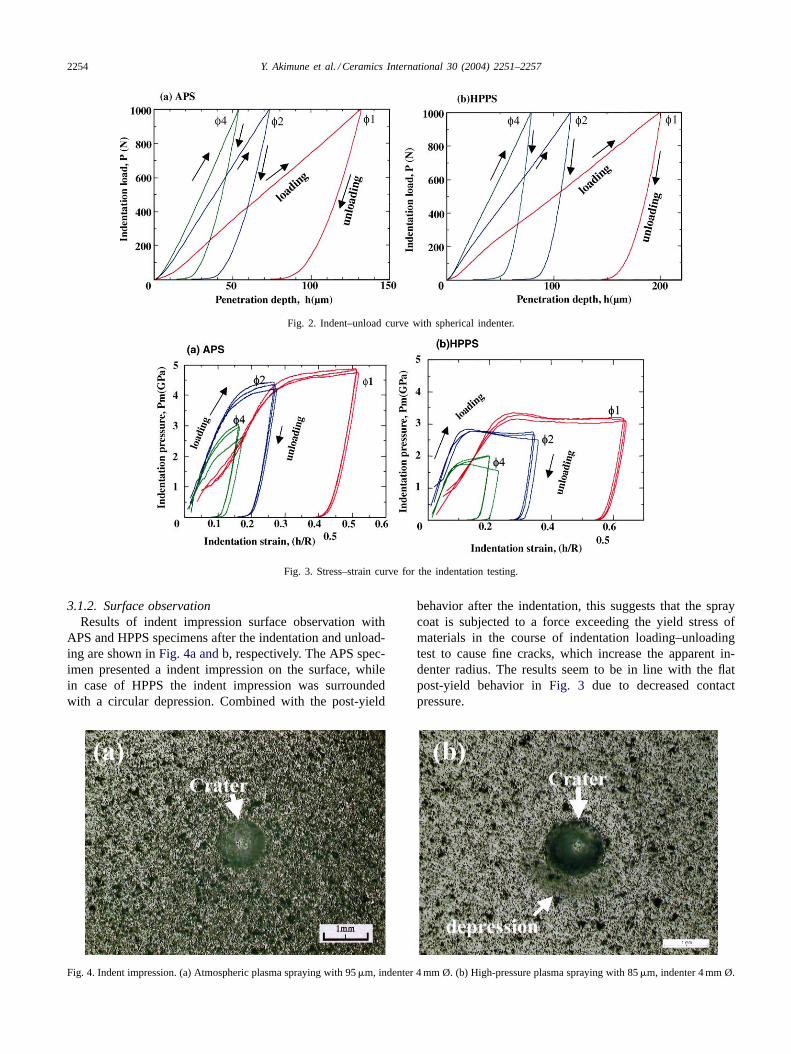
3.1.2. Surface observationResults of indent impression surface observation with
APS and HPPS specimens after the indentation and unload-ing are shown inFig. 4a and b, respectively. The APS spec-imen presented a indent impression on the surface, whilein case of HPPS the indent impression was surroundedwith a circular depression. Combined with the post-yield
Fig. 4. Indent impression. (a) Atmospheric plasma spraying with 95�m, indenter 4 mm Ø. (b) High-pressure plasma spraying with 85�m, indenter 4 mm Ø.
behavior after the indentation, this suggests that the spraycoat is subjected to a force exceeding the yield stress ofmaterials in the course of indentation loading–unloadingtest to cause fine cracks, which increase the apparent in-denter radius. The results seem to be in line with the flatpost-yield behavior inFig. 3 due to decreased contactpressure.
Y. Akimune et al. / Ceramics International 30 (2004) 2251–2257 2255
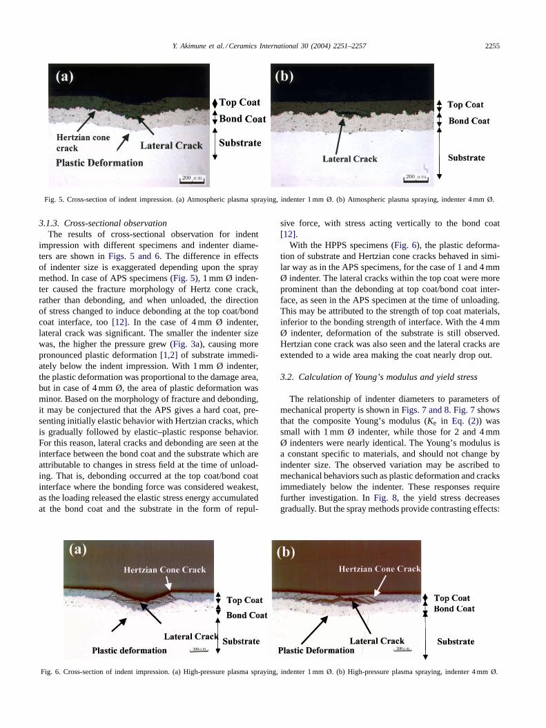
Fig. 5. Cross-section of indent impression. (a) Atmospheric plasma spraying, indenter 1 mm Ø. (b) Atmospheric plasma spraying, indenter 4 mm Ø.
3.1.3. Cross-sectional observationThe results of cross-sectional observation for indent
impression with different specimens and indenter diame-ters are shown inFigs. 5 and 6. The difference in effectsof indenter size is exaggerated depending upon the spraymethod. In case of APS specimens (Fig. 5), 1 mm Ø inden-ter caused the fracture morphology of Hertz cone crack,rather than debonding, and when unloaded, the directionof stress changed to induce debonding at the top coat/bondcoat interface, too[12]. In the case of 4 mm Ø indenter,lateral crack was significant. The smaller the indenter sizewas, the higher the pressure grew (Fig. 3a), causing morepronounced plastic deformation[1,2] of substrate immedi-ately below the indent impression. With 1 mm Ø indenter,the plastic deformation was proportional to the damage area,but in case of 4 mm Ø, the area of plastic deformation wasminor. Based on the morphology of fracture and debonding,it may be conjectured that the APS gives a hard coat, pre-senting initially elastic behavior with Hertzian cracks, whichis gradually followed by elastic–plastic response behavior.For this reason, lateral cracks and debonding are seen at theinterface between the bond coat and the substrate which areattributable to changes in stress field at the time of unload-ing. That is, debonding occurred at the top coat/bond coatinterface where the bonding force was considered weakest,as the loading released the elastic stress energy accumulatedat the bond coat and the substrate in the form of repul-
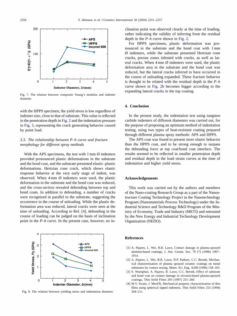
Fig. 6. Cross-section of indent impression. (a) High-pressure plasma spraying, indenter 1 mm Ø. (b) High-pressure plasma spraying, indenter 4 mm Ø.
sive force, with stress acting vertically to the bond coat[12].
With the HPPS specimens (Fig. 6), the plastic deforma-tion of substrate and Hertzian cone cracks behaved in simi-lar way as in the APS specimens, for the case of 1 and 4 mmØ indenter. The lateral cracks within the top coat were moreprominent than the debonding at top coat/bond coat inter-face, as seen in the APS specimen at the time of unloading.This may be attributed to the strength of top coat materials,inferior to the bonding strength of interface. With the 4 mmØ indenter, deformation of the substrate is still observed.Hertzian cone crack was also seen and the lateral cracks areextended to a wide area making the coat nearly drop out.
3.2. Calculation of Young’s modulus and yield stress
The relationship of indenter diameters to parameters ofmechanical property is shown inFigs. 7 and 8. Fig. 7showsthat the composite Young’s modulus (Ke in Eq. (2)) wassmall with 1 mm Ø indenter, while those for 2 and 4 mmØ indenters were nearly identical. The Young’s modulus isa constant specific to materials, and should not change byindenter size. The observed variation may be ascribed tomechanical behaviors such as plastic deformation and cracksimmediately below the indenter. These responses requirefurther investigation. InFig. 8, the yield stress decreasesgradually. But the spray methods provide contrasting effects:
2256 Y. Akimune et al. / Ceramics International 30 (2004) 2251–2257
Fig. 7. The relation between composite Young’s modulus and indenterdiameter.
with the HPPS specimen, the yield stress is low regardless ofindenter size, close to that of substrate. This value is reflectedin the penetration depth inFig. 2and the indentation pressurein Fig. 3, representing the crack generating behavior causedby point load.
3.3. The relationship between P–h curve and fracturemorphology for different spray methods
With the APS specimens, the test with 1 mm Ø indentersprovided pronounced plastic deformations in the substrateand the bond coat, and the substrate presented elastic–plasticdeformations. Hertzian cone crack, which shows elasticresponse behavior at the very early stage of indent, wasobserved. When 4 mm Ø indenters were used, the plasticdeformation in the substrate and the bond coat was reduced,and the cross-section revealed debonding between top andbond coats. In addition to debonding, a number of crackswere recognized in parallel to the substrate, suggesting theoccurrence in the course of unloading. While the plastic de-formation area was reduced, lateral cracks were seen at thetime of unloading. According to Ref.[4], debonding in thecourse of loading can be judged on the basis of inclinationpoint in theP–h curve. In the present case, however, no in-
Fig. 8. The relation between yielding stress and indentation diameter.
clination point was observed clearly at the time of loading,rather indicating the validity of inferring from the residualdepth in theP–h curve shown inFig. 2.
For HPPS specimens, plastic deformation was pro-nounced in the substrate and the bond coat with 1 mmØ indenters, while the substrate presented Hertzian conecracks, porous zones infested with cracks, as well as lat-eral cracks. When 4 mm Ø indenters were used, the plasticdeformation area in the substrate and the bond coat wasreduced, but the lateral cracks inferred to have occurred inthe course of unloading expanded. These fracture behavioris thought to be related with the residual depth in theP–hcurve shown inFig. 2b becomes bigger according to theexpanding lateral cracks in the top coating.
4. Conclusion
In the present study, the indentation test using tungstencarbide indenters of different diameters was carried out, forthe purpose of proposing an optimum method of indentationtesting, using two types of heat-resistant coating preparedthrough different plasma spray methods: APS and HPPS.
The APS coat was found to present more elastic behaviorthan the HPPS coat, and to be strong enough to surpassthe debonding force at top coat/bond coat interface. Theresults seemed to be reflected in smaller penetration depthand residual depth in the load–strain curves at the time ofindentation and higher yield stress.
Acknowledgements
This work was carried out by the authors and membersof the Nano-coating Research Group as a part of the Nanos-tructure Coating Technology Project in the NanotechnologyProgram (Nanomaterials Process Technology) under the In-dustrial Science and Technology R&D Program of the Min-istry of Economy, Trade and Industry (METI) and entrustedby the New Energy and Industrial Technology DevelopmentOrganization (NEDO).
References
[1] A. Pajares, L. Wei, B.R. Lawn, Contact damage in plasma-sprayedalumina-based coatings, J. Am. Ceram. Soc. 79 (7) (1996) 1907–1914.
[2] A. Pajares, L. Wei, B.R. Lawn, N.P. Padture, C.C. Berndt, Mechan-ical characterization of plasma sprayed ceramic coatings on metalsubstrates by contact testing, Mater. Sci. Eng. A208 (1996) 158–165.
[3] S. Wuttiphan, A. Pajares, B. Lawn, C.C. Berndt, Effect of substrateand bond coat on contact damage in zirconia-based plasma-sprayedcoatings, Thin Solid Films 293 (1997) 251–260.
[4] M.V. Swain, J. Mencık, Mechanical property characterization of thinfilms using spherical tipped indenters, Thin Solid Films 253 (1994)204–211.

Y. Akimune et al. / Ceramics International 30 (2004) 2251–2257 2257
[5] K.-S. Lee, S. Wuttiphan, X.-Z. Hu, S.-K. Lee, B.R. Lawn, Contact-induced transverse fractures in brittle layers on soft substrate: astudy on silicon nitride bilayers, J. Am. Ceram. Soc. 81 (3) (1988)571–580.
[6] H.R. Hertz, Hert’s Miscellaneous Papers, Macmillan, London, 1896(Chapters 5 and 6).
[7] S.P. Timoshenko, J.N. Goodier, Theory of Elasticity, 3rd ed.,McGraw-Hill Book Company, pp. 409–415.
[8] K.L. Johnson, Contact Mechanics, Cambridge University Press,pp. 84–106.
[9] B.R. Lawn, Indentation of ceramics with spheres: a century afterHertz, J. Am. Ceram. Soc. 81 (8) (1998) 1977–1994.
[10] S. Sodeoka, M. Suzuki, K. Ueno, Effects of high-pressure plasmaspraying for yttria-stabilized zirconia coating, J. Therm. Spray Tech-nol. 5 (3) (1996) 277–282.
[11] S. Shimizu, Ph.D. Dissertation (in Japanese), Toyoshashi Institute ofTechnology, 2001.
[12] D.B. Marshall, B.R. Lawn, A.G. Evans, Elastic/plastic indentationdamage in ceramics—the lateral crack system, J. Am. Ceram. Soc.65 (11) (1982) 561–566.


![Comparison between the fracture strength and …...Nonetheless, the zirconia core is less translucent than other dental all-ceramic materials such as glass-ceramics [40, 56]. Lithium](https://img.pdfslide.us/doc/110x75/5eafc4297c3ce22ce85b3add/comparison-between-the-fracture-strength-and-nonetheless-the-zirconia-core.jpg)