Embed Size (px)
Citation preview
Installation Instructions
POINT I/O RTD and Isolated Thermocouple Input ModulesCatalog Numbers 1734-IR2 and 1734-IT2I, Series C
Inside…
For This Topic See Page
Important User Information 2
Preventing Electrostatic Discharge 3
Environment and Enclosure 4
Before You Begin 5
Identify Module Components 5
Install the Mounting Base 7
Install the Module 8
Install the Removable Terminal Block (RTB) 10
Remove a Mounting Base 11
Communicate with Your Module 12
Wire the Module 14
Troubleshoot with Indicators 17
North American Hazardous Location Approval 20
European Hazardous Location Approval 21
Specifications 22
Publication 1734-IN011C-EN-E - June 2005

2 POINT I/O RTD and Isolated Thermocouple Input Modules
Important User InformationSolid state equipment has operational characteristics differing from those of electromechanical equipment. Safety Guidelines for the Application, Installation and Maintenance of Solid State Controls (Publication SGI-1.1 available from your local Rockwell Automation sales office or online at http://literature.rockwellautomation.com) describes some important differences between solid state equipment and hard-wired electromechanical devices. Because of this difference, and also because of the wide variety of uses for solid state equipment, all persons responsible for applying this equipment must satisfy themselves that each intended application of this equipment is acceptable.In no event will Rockwell Automation, Inc. be responsible or liable for indirect or consequential damages resulting from the use or application of this equipment.The examples and diagrams in this manual are included solely for illustrative purposes. Because of the many variables and requirements associated with any particular installation, Rockwell Automation, Inc. cannot assume responsibility or liability for actual use based on the examples and diagrams.No patent liability is assumed by Rockwell Automation, Inc. with respect to use of information, circuits, equipment, or software described in this manual.Reproduction of the contents of this manual, in whole or in part, without written permission of Rockwell Automation, Inc., is prohibited.Throughout this manual, when necessary, we use notes to make you aware of safety considerations.
WARNING Identifies information about practices or circumstances that can cause an explosion in a hazardous environment, which may lead to personal injury or death, property damage, or economic loss.
IMPORTANT Identifies information that is critical for successful application and understanding of the product.
ATTENTION Identifies information about practices or circumstances that can lead to personal injury or death, property damage, or economic loss. Attentions help you:
• identify a hazard• avoid a hazard• recognize the consequence
SHOCK HAZARD Labels may be located on or inside the equipment (e.g., drive or motor) to alert people that dangerous voltage may be present.
BURN HAZARD Labels may be located on or inside the equipment (e.g., drive or motor) to alert people that surfaces may be dangerous temperatures.
Publication 1734-IN011C-EN-E - June 2005

POINT I/O RTD and Isolated Thermocouple Input Modules 3
ATTENTION Preventing Electrostatic Discharge
This equipment is sensitive to electrostatic discharge, which can cause internal damage and affect normal operation. Follow these guidelines when you handle this equipment:
• Touch a grounded object to discharge potential static.
• Wear an approved grounding wriststrap.
• Do not touch connectors or pins on component boards.
• Do not touch circuit components inside the equipment.
• If available, use a static-safe workstation.
• When not in use, store the equipment in appropriate static-safe packaging.
Publication 1734-IN011C-EN-E - June 2005
4 POINT I/O RTD and Isolated Thermocouple Input Modules
ATTENTION Environment and Enclosure
This equipment is intended for use in a Pollution Degree 2 industrial environment, in overvoltage Category II applications (as defined in IEC publication 60664-1), at altitudes up to 2000 meters without derating.
This equipment is considered Group 1, Class A industrial equipment according to IEC/CISPR Publication 11. Without appropriate precautions, there may be potential difficulties ensuring electromagnetic compatibility in other environments due to conducted as well as radiated disturbance.
This equipment is supplied as “open type” equipment. It must be mounted within an enclosure that is suitably designed for those specific environmental conditions that will be present and appropriately designed to prevent personal injury resulting from accessibility to live parts. The interior of the enclosure must be accessible only by the use of a tool. Subsequent sections of this publication may contain additional information regarding specific enclosure type ratings that are required to comply with certain product safety certifications.
See NEMA Standards publication 250 and IEC publication 60529, as applicable, for explanations of the degrees of protection provided by different types of enclosure. Also, see the appropriate sections in this publication, as well as the Allen-Bradley publication 1770-4.1 (“Industrial Automation Wiring and Grounding Guidelines”), for additional installation requirements pertaining to this equipment.
Publication 1734-IN011C-EN-E - June 2005

POINT I/O RTD and Isolated Thermocouple Input Modules 5
Before You Begin You can use these Series C modules with the following:
• ControlNet adapters with RSLogix 5000 software version 11 or higher
• DeviceNet adapters
• EtherNet/IP adapters with RSLogix 5000 software version 11 or higher
• PROFIBUS adapters
Identify Module Components Use the figures to identify the external features of the modules.
RTDInput
Module
Status
Network
Status
NODE:
0
1
InterlockingSide Pieces
DIN Rail Locking Screw (orange) Removable Terminal Block (RTB)
Slide-in Writable Label
Insertable I/O Module
Module Wiring Diagram
Mounting Base
RTB Removable Handle
Module LockingMechanism
Mechanical Keying (orange)
1734-IR2 POINT I/O RTD Input Module
41825IR2
The wiring base assembly includes terminal base, 1734-TB or 1734-TBS, which consists of a mounting base, 1734-MB, and removable terminal block, 1734-RTB or 1734-RTBS.
Publication 1734-IN011C-EN-E - June 2005

6 POINT I/O RTD and Isolated Thermocouple Input Modules
Relay
Output
Module
Status
Network
Status
NODE:
0
1
1734OX2
InterlockingSide Pieces
DIN Rail Locking Screw (orange)
Removable Terminal Block (RTB)
Slide-in Writable Label Insertable I/O Module
Module Wiring Diagram
Mounting Base
RTB Removable Handle
Module Locking Mechanism
Mechanical Keying (orange)
1734-IT2I POINT I/O Isolated Thermocouple Input Module
41825IT
The wiring base assembly is terminal base, 1734-TBCJC, which consists of a mounting base, 1734-MB, and removable terminal block, 1734-RTBCJC.
Publication 1734-IN011C-EN-E - June 2005

POINT I/O RTD and Isolated Thermocouple Input Modules 7
Install the Mounting BaseTo install the mounting base on the DIN rail, proceed as follows.
1. Position the mounting base vertically above the installed units (adapter, power supply, or existing module).
2. Slide the mounting base down so that the interlocking side pieces engage the adjacent module or adapter.
3. Press firmly to seat the mounting base on the DIN rail.
The mounting base will snap into place.
ATTENTION POINT I/O is grounded through the DIN rail to chassis ground. Use zinc-plated, yellow-chromated steel DIN rail to assure proper grounding. The use of DIN rail materials (e.g., aluminum, plastic, etc.) that can corrode, oxidize, or are poor conductors can result in improper or intermittent grounding.
Secure DIN rail to mounting surface approximately every 200 mm.
ATTENTION Do not discard the end cap shipped with an adapter or communication interface. Use this end cap to cover the exposed interconnections on the last mounting base on the DIN rail. Failure to do so could result in equipment damage or injury from electric shock.
Publication 1734-IN011C-EN-E - June 2005

8 POINT I/O RTD and Isolated Thermocouple Input Modules
Install the Module
Install the module before or after base installation. Make sure that you:
• correctly keyed the mounting base before installing the module into the mounting base
• positioned the mounting base locking screw horizontal with reference to the base
To install the module, proceed as follows.
1. Using a bladed screwdriver, rotate the keyswitch on the mounting base clockwise until the number required for the type of module you are installing aligns with the notch in the base.
2. Make certain the DIN rail locking screw is in the horizontal position.
WARNING When you insert or remove the module while backplane power is on, an electrical arc can occur. This could cause an explosion in hazardous location installations.
Be sure that power is removed or the area is nonhazardous before proceeding. Repeated electrical arcing causes excessive wear to contacts on both the module and its mating connector. Worn contacts may create electrical resistance that can affect module operation.
Notch (position 3 shown)
Turn the keyswitch to align the number with the notch.
44009
Publication 1734-IN011C-EN-E - June 2005

POINT I/O RTD and Isolated Thermocouple Input Modules 9
You cannot insert the module if you unlocked the locking mechanism.
3. Insert the module straight down into the mounting base and press to secure.
The module locks into place.
Be sure the DIN rail locking screw is in the horizontal position.
44010
24VDC
Source
Output
Module
Status
Network
Status
1734OB4E
NODE:
0
1
2
3
44012
Publication 1734-IN011C-EN-E - June 2005

10 POINT I/O RTD and Isolated Thermocouple Input Modules
Install the Removable Terminal Block (RTB)A removable terminal block comes with your wiring base assembly. To remove, pull up on the RTB handle. You can now remove the mounting base and replace as necessary without removing any of the wiring. To reinsert the removable terminal block, proceed as follows.
1. Insert the end oppOSIte the handle into the base unit.
This end has a curved section that engages with the wiring base.
2. Rotate the terminal block into the wiring base until it locks itself in place.
3. If an I/O module is installed, snap the RTB handle into place
on the module.
WARNING When you connect or disconnect the removable terminal block (RTB) with field-side power applied, an electrical arc can occur. This could cause an explosion in hazardous location installations. Be sure that power is removed or the area is nonhazardous before proceeding.
Hook the RTB end into the mounting base end, and rotate until it locks into place.
44011
Publication 1734-IN011C-EN-E - June 2005
POINT I/O RTD and Isolated Thermocouple Input Modules 11
Remove a Mounting BaseTo remove a mounting base, you must remove any installed module, and the module installed in the base to the right. Remove the removable terminal block (if wired).
1. Unlatch the RTB handle on the I/O module.
2. Pull on the RTB handle to remove the removable terminal block.
3. Press on the module lock on the top of the module.
4. Pull on the I/O module to remove from the base.
5. Repeat steps 1, 2, 3, and 4 for the module to the right.
6. Use a small-bladed screwdriver to rotate the orange, base- locking screw to a vertical position.
This releases the locking mechanism.
7. Lift straight up to remove.
WARNING When you connect or disconnect the removable terminal block (RTB) with field-side power applied, an electrical arc can occur. This could cause an explosion in hazardous location installations.
Be sure that power is removed or the area is nonhazardous before proceeding.
Publication 1734-IN011C-EN-E - June 2005

12 POINT I/O RTD and Isolated Thermocouple Input Modules
Communicate with Your ModulePOINT I/O modules send (consume) and receive (produce) I/O messages. You map these messages into the processor’s memory.
The 1734-RTD module produces 6 bytes of input data (scanner Rx) and fault status data. The 1734-IT2I module produces 8 bytes of input data (scanner Rx) and fault status data.
The modules do not consume I/O data (scanner Tx).
Default Data Map for 1734-IR2 RTD Input Module
Message size: 6 Bytes
Produces (scanner Rx)
Input Channel 0 - High Byte Input Channel 0 - Low Byte
Input Channel 1 - High Byte Input Channel 1 - Low Byte
Status Byte for Channel 1 Status Byte for Channel 0
OR
UR
HHA
LLA
HA
LA
CM
CF
OR
UR
HHA
LLA
HA
LA
CM
CF
Consumes (scanner Tx)
No consumed data
Where: CF = Channel Fault status; 0 = no error, 1 = fault
CM = Calibration Mode; 0 = normal, 1 = calibration modeLA = Low Alarm; 0 = no error, 1 = faultHA = High Alarm; 0 = no error, 1 = faultLLA = Low/Low Alarm; 0 = no error, 1 = faultHHA = High/High Alarm; 0 = no error, 1 = faultUR = Underrange; 0 = no error, 1 = faultOR = Overrange; 0 = no error, 1 = fault
Publication 1734-IN011C-EN-E - June 2005

POINT I/O RTD and Isolated Thermocouple Input Modules 13
Default Data Map for 1734-IT2I Isolated Thermocouple Input Module
Message size: 8 Bytes
Produces (scanner Rx)
Input Channel 0 - High Byte Input Channel 0 - Low Byte
Input Channel 1 - High Byte Input Channel 1 - Low Byte
Status Byte for Channel 1 Status Byte for Channel 0
OR
UR
HHA
LLA
HA
LA
CM
CF
OR
UR
HHA
LLA
HA
LA
CM
OR
UR
Cold Junction Temperature (Selectable: Channel 0, Channel 1, or Average of both Channel 0 and 1)
Consumes (scanner Tx)
No consumed data
Where: CF = Channel Fault status; 0 = no error, 1 = fault
CM = Calibration Mode; 0 = normal, 1 = calibration modeLA = Low Alarm; 0 = no error, 1 = faultHA = High Alarm; 0 = no error, 1 = faultLLA = Low/Low Alarm; 0 = no error, 1 = faultHHA = High/High Alarm; 0 = no error, 1 = faultUR = Underrange; 0 = no error, 1 = faultOR = Overrange; 0 = no error, 1 = fault
Publication 1734-IN011C-EN-E - June 2005
14 POINT I/O RTD and Isolated Thermocouple Input Modules
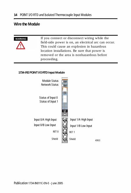
Wire the Module
WARNING If you connect or disconnect wiring while the field-side power is on, an electrical arc can occur. This could cause an explosion in hazardous location installations. Be sure that power is removed or the area is nonhazardous before proceeding.
1734-IR2 POINT I/O RTD Input Module
Module StatusNetwork Status
Status of Input 0Status of Input 1
Input 0/A High Input Input 1/A High Input
RET 1
Input 1/B Low InputInput 0/B Low Input
RET 0
Shield Shield 43922
Publication 1734-IN011C-EN-E - June 2005

POINT I/O RTD and Isolated Thermocouple Input Modules 15
Channel High Signal (+) Low Signal (-) Return Shield
In 0/A 0 4 6
In 0/B 2
In 1/A 1 5 7
In 1/B 3
1734-IR2 POINT I/O RTD Input Module
3-wire RTD
2-wire RTD
When using 2-wire RTDs, jumper In/B to RET.
42017R2
In = Input channelRET = Sensor returnShield = Sensor cable shield
In 0/A
In 1/A
In 1/BIn 0/B
RET 0 RET 1
ShieldShield
3
5
0 1
2
4
6 7
Publication 1734-IN011C-EN-E - June 2005

16 POINT I/O RTD and Isolated Thermocouple Input Modules
Channel Input High Input Low Shield
0+ 4 3
0- 5
1+ 6 3
1- 7
Power is provided by the internal power bus.
43923
Module StatusNetwork Status
Status of Input 0
Status of Input 1
0+
1+
In/A = Chassis groundIn/B = CommonRET = SupplySHLD = Shield
1734-IT2I POINT I/O Isolated Thermocouple Input Module
Shield
0-
1-
1734-IT2I POINT I/O Isolated Thermocouple Input Module
Shield
0+ 0-
1-1+
0+ = Input channel 0 High0- = Input channel 0 Low1+ = Input channel 1 High1- = Input channel 1 Low
42017IR
3
5
7
4
6
Thermocouple 0
Thermocouple 1
Publication 1734-IN011C-EN-E - June 2005

POINT I/O RTD and Isolated Thermocouple Input Modules 17
Troubleshoot with IndicatorsUse the status indicators to troubleshoot your modules. Refer to the following graphics that show status indicators for the modules. Refer to the following table to troubleshoot your modules.
1734-IR2 POINT I/O RTD Input Module
1734-IT2I POINT I/O Isolated Thermocouple Input Module
Module StatusNetwork Status
Status of Input 0
Status of Input 1
43922
Module StatusNetwork Status
43923
Status of Input 0
Status of Input 1
Publication 1734-IN011C-EN-E - June 2005

18 POINT I/O RTD and Isolated Thermocouple Input Modules
Indication Probable Cause
Module Status
Off No power is applied to device.
Green Device is operating normally.
Flashing Green Device needs commissioning due to configuration missing, incomplete, or incorrect.
Flashing Red Recoverable fault is present.
Red Unrecoverable fault may require device replacement.
Flashing Red/Green Device is in self-test.
Indication Probable Cause
Network Status
Off Device is not online.- Device has not completed dup_MAC_id test.- Device not powered. Check module status indicator.
Flashing Green Device is online but has no connections in the established state.
Green Device is online and has connections in the established state.
Flashing Red One or more I/O connections are in timed-out state.
Red Critical link failure is present with failed communication device. Device detected error that prevents it communicating on the network.
Flashing Red/Green
Communication faulted device is present. The device detected a network access error and is in communication faulted state. Device received and accepted an Identify Communication Faulted Request - long protocol message.
Publication 1734-IN011C-EN-E - June 2005

POINT I/O RTD and Isolated Thermocouple Input Modules 19
Indication Probable Cause
Channel Status
Off Module is in CAL mode.
Solid Green Normal operation is present with channel scanning inputs.
Flashing Green Channel is being calibrated.
Solid Red Major channel fault is present.
Flashing Red Channel is at end of range (over or under).
Publication 1734-IN011C-EN-E - June 2005

20 POINT I/O RTD and Isolated Thermocouple Input Modules
North American Hazardous Location Approval
The following information applies when operating this equipment in hazardous locations:
Informations sur l’utilisation de cet équipement en environnements dangereux:
Products marked “CL I, DIV 2, GP A, B, C, D” are suitable for use in Class I Division 2 Groups A, B, C, D, Hazardous Locations and nonhazardous locations only. Each product is supplied with markings on the rating nameplate indicating the hazardous location temperature code. When combining products within a system, the most adverse temperature code (lowest “T” number) may be used to help determine the overall temperature code of the system. Combinations of equipment in your system are subject to investigation by the local Authority Having Jurisdiction at the time of installation.
Les produits marqués “CL I, DIV 2, GP A, B, C, D” ne conviennent qu’à une utilisation en environnements de Classe I Division 2 Groupes A, B, C, D dangereux et non dangereux. Chaque produit est livré avec des marquages sur sa plaque d’identification qui indiquent le code de température pour les environnements dangereux. Lorsque plusieurs produits sont combinés dans un système, le code de température le plus défavorable (code de température le plus faible) peut être utilisé pour déterminer le code de température global du système. Les combinaisons d’équipements dans le système sont sujettes à inspection par les autorités locales qualifiées au moment de l’installation.
EXPLOSION HAZARD -• Do not disconnect equipment unless
power has been removed or the area is known to be nonhazardous.
• Do not disconnect connections to this equipment unless power has been removed or the area is known to be nonhazardous. Secure any external connections that mate to this equipment by using screws, sliding latches, threaded connectors, or other means provided with this product.
• Substitution of components may impair suitability for Class I, Division 2.
• If this product contains batteries, they must only be changed in an area known to be nonhazardous.
RISQUE D’EXPLOSION – • Couper le courant ou s’assurer que
l’environnement est classé non dangereux avant de débrancher l'équipement.
• Couper le courant ou s'assurer que l’environnement est classé non dangereux avant de débrancher les connecteurs. Fixer tous les connecteurs externes reliés à cet équipement à l'aide de vis, loquets coulissants, connecteurs filetés ou autres moyens fournis avec ce produit.
• La substitution de composants peut rendre cet équipement inadapté à une utilisation en environnement de Classe 1, Division 2.
• S’assurer que l’environnement est classé non dangereux avant de changer les piles.
WARNING AVERTISSEMENT
Publication 1734-IN011C-EN-E - June 2005

POINT I/O RTD and Isolated Thermocouple Input Modules 21
European Hazardous Location Approval
European Zone 2 Certification (The following applies when the product bears the EEx marking)This equipment is intended for use in potentially explosive atmospheres as defined by European Union Directive 94/9/EC.DEMKO certifies that this equipment has been found to comply with the Essential Health and Safety Requirements relating to the design and construction of Category 3 equipment intended for use in potentially explosive atmospheres, given in Annex II to this Directive. The examination and test results are recorded in confidential report No 03NK30347.Compliance with the Essential Health and Safety Requirements has been assured by compliance with EN 50021.
IMPORTANT Observe the following additional Zone 2 certification requirements.
This equipment is not resistant to sunlight or other sources of UV radiation.
The secondary of a current transformer shall not be open-circuited when applied in Class I, Zone 2 environments.
Equipment of lesser Enclosure Type Rating must be installed in an enclosure providing at least IP54 protection when applied in Class I, Zone 2 environments.
This equipment shall be used within its specified ratings defined by Allen-Bradley.
Provision shall be made to prevent the rated voltage from being exceeded by transient disturbances of more than 40% when applied in Class I, Zone 2 environments.
Publication 1734-IN011C-EN-E - June 2005

22 POINT I/O RTD and Isolated Thermocouple Input Modules
Specifications
Specifications - 1734-IR2 POINT I/O RTD Input Module
Input Specifications
Number of Inputs 2 single-ended, non-isolated
Resolution 16 bits9.5 mΩ/cnt 0.03 °C/cnt (Pt385 @ 25 °C)
Input Range 0-600Ω
Sensors Supported 100Ω Ptα = 0.00385 Euro(-200…+870 °C)200Ω Ptα = 0.00385 Euro(-200…+630 °C)100Ω Ptα = 0.003916 U.S.(-200…+630 °C)200Ω Ptα = 0.003916 U.S.(-200…+630 °C)10Ω Cuα = 0.00427(-200…+260 °C)100Ω Niα = 0.00618(-60…+250 °C)120Ω Niα = 0.00672(-60…+250 °C)120Ω Niα = 0.00618(-60…+250 °C)
Absolute Accuracy1 0.1% Full Scale @ 25 oC
Accuracy Drift w/Temp. 30ppm/oC
Input Update Rate
(per module)
40 ms @ Notch = 50Hz33 ms @ Notch = 60 Hz (default)20 ms @ Notch = 100 Hz17 ms @ Notch = 120 Hz10 ms @ Notch = 200 Hz8 ms @ Notch = 240 Hz7 ms @ Notch = 300 Hz5 ms @ Notch = 400 Hz4 ms @ Notch = 480 Hz
Publication 1734-IN011C-EN-E - June 2005
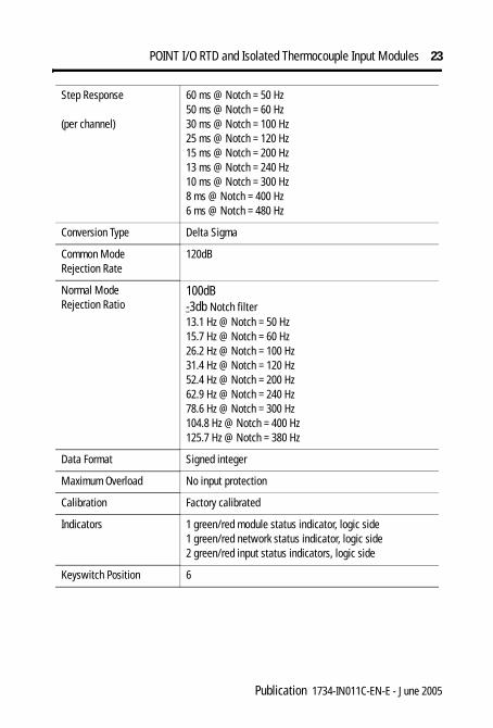
POINT I/O RTD and Isolated Thermocouple Input Modules 23
Step Response
(per channel)
60 ms @ Notch = 50 Hz50 ms @ Notch = 60 Hz30 ms @ Notch = 100 Hz25 ms @ Notch = 120 Hz15 ms @ Notch = 200 Hz13 ms @ Notch = 240 Hz10 ms @ Notch = 300 Hz8 ms @ Notch = 400 Hz6 ms @ Notch = 480 Hz
Conversion Type Delta Sigma
Common ModeRejection Rate
120dB
Normal Mode Rejection Ratio
100dB-3db Notch filter13.1 Hz @ Notch = 50 Hz15.7 Hz @ Notch = 60 Hz26.2 Hz @ Notch = 100 Hz31.4 Hz @ Notch = 120 Hz52.4 Hz @ Notch = 200 Hz62.9 Hz @ Notch = 240 Hz78.6 Hz @ Notch = 300 Hz104.8 Hz @ Notch = 400 Hz125.7 Hz @ Notch = 380 Hz
Data Format Signed integer
Maximum Overload No input protection
Calibration Factory calibrated
Indicators 1 green/red module status indicator, logic side1 green/red network status indicator, logic side2 green/red input status indicators, logic side
Keyswitch Position 6
Publication 1734-IN011C-EN-E - June 2005

24 POINT I/O RTD and Isolated Thermocouple Input Modules
Specifications - 1734-IT2I POINT I/O Isolated Thermocouple Input Module
Input Specifications
Number of Inputs 2 differential, individually isolated
Resolution (also seeThermocouple Type)
15 bits plus sign2.5µV/cnt
Thermocouple Type (and resolution average over span)
Sensor Range Resolution (Average Over Span)Type B 30…1820 °C 3 counts/ °CType C 0…2315 °C 6 counts/ °CType E -270…1000 °C 24 counts/°CType J -210…1200 °C 21 counts/°CType K -270…1372 °C 13 counts/°CType N -270…1300 °C 11 counts/°CType R -50…1768.1 °C 4 counts/°CType S -50…1768.1 °C 4 counts/°CType T -270…400 °C 15 counts/°C
Cold Junction Compensation
Included in 1734-RTBCJC remote termination block
Cold Junction Compensation Range
0…70 °C
Input Voltage +75mV
Absolute Accuracy1 0.1% Full Scale @ 25 oC
Accuracy Drift w/Temp. 30ppm/oC
Input Impedance 100KΩ
Input Resistance 1MΩ
Conversion Type Delta Sigma
Data Format Signed integer
Maximum Overload Input not overvoltage protected
Calibration Factory calibrated
Publication 1734-IN011C-EN-E - June 2005

POINT I/O RTD and Isolated Thermocouple Input Modules 25
Input Update Rate
(per module)
20 ms @ Notch = 50 Hz17 ms @ Notch = 60 Hz (default)10 ms @ Notch = 100 Hz8 ms @ Notch = 120 Hz5 ms @ Notch = 200 Hz4 ms @ Notch = 240 Hz3 ms @ Notch = 300 Hz3 ms @ Notch = 400 Hz2 ms @ Notch = 480 Hz
Step Response per Channel
60 ms @ Notch = 50 Hz50 ms @ Notch = 60 Hz30 ms @ Notch = 100 Hz25 ms @ Notch = 120 Hz15 ms @ Notch = 200 Hz13 ms @ Notch = 240 Hz10 ms @ Notch = 300 Hz8 ms @ Notch = 400 Hz6 ms @ Notch = 480 Hz
Common Mode Rejection Ratio
120dB
Normal Mode Rejection Ratio
-60dB-3db Notch filter13.1 Hz @ Notch = 50 Hz15.7 Hz @ Notch = 60 Hz26.2 Hz @ Notch = 100 Hz31.4 Hz @ Notch = 120 Hz52.4 Hz @ Notch = 200 Hz62.9 Hz @ Notch = 240 Hz78.6 Hz @ Notch = 300 Hz104.8 Hz @ Notch = 400 Hz125.7 Hz @ Notch = 380 Hz
Indicators 1 green/red module status indicator, logic side1 green/red network status indicator, logic side2 green/red input status indicators, logic side
Keyswitch Position 6
Publication 1734-IN011C-EN-E - June 2005

26 POINT I/O RTD and Isolated Thermocouple Input Modules
General Specifications 1734-IR2 1734-IT2I
Module Location 1734-TB or 1734-TBS wiring base assembly
1734-TBCJC wiring base assembly
POINTBus Current 220 mA @ 5V dc 175 mA @ 5V dc
Power Dissipation 1.0W maximum
Thermal Dissipation 3.3 BTU/Hr maximum
Isolation Voltage(Continuous-voltageWithstand Rating)
50V continuousTested to withstand 2200V dc for 60 s
External dc power No external supply required-
Dimensions (HxWXD) 56 x 12 x 75.5 mm (2.21 x 0.47 x 2.97 in)
Operational Temperature IEC 60068-2-1 (Test Ad, Operating Cold),IEC 60068-2-2 (Test Bd, Operating Dry Heat),IEC 60068-2-14 (Test Nb, Operating Thermal Shock):-20…55 °C (-4…131 °F)
Storage Temperature IEC 60068-2-1 (Test Ab, Unpackaged Nonoperating Cold),IEC 60068-2-2 (Test Bb, Unpackaged Nonoperating Dry Heat),IEC 60068-2-14 (Test Na, Unpackaged Nonoperating Thermal Shock):-40…85 °C (-40…185 °F)
Relative Humidity IEC 60068-2-30 (Test Db, Unpackaged Nonoperating Damp Heat):5…95% noncondensing
Shock, Operating Non-operatings
EC 60068-2-27 (Test Ea, Unpackaged Shock)30 g 50 g
Vibration IEC60068-2-6 (Test Fc, Operating)5 g @ 10...500 Hz
ESD Immunity IEC6100-4-26 kV contact discharges8 kV air discharges
Publication 1734-IN011C-EN-E - June 2005
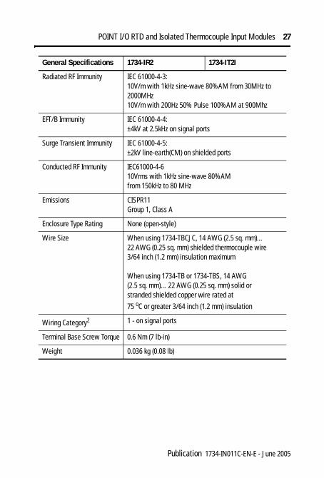
POINT I/O RTD and Isolated Thermocouple Input Modules 27
Radiated RF Immunity IEC 61000-4-3:10V/m with 1kHz sine-wave 80%AM from 30MHz to 2000MHz10V/m with 200Hz 50% Pulse 100%AM at 900Mhz
EFT/B Immunity IEC 61000-4-4:±4kV at 2.5kHz on signal ports
Surge Transient Immunity IEC 61000-4-5:±2kV line-earth(CM) on shielded ports
Conducted RF Immunity IEC61000-4-610Vrms with 1kHz sine-wave 80%AM from 150kHz to 80 MHz
Emissions CISPR11Group 1, Class A
Enclosure Type Rating None (open-style)
Wire Size When using 1734-TBCJC, 14 AWG (2.5 sq. mm)…22 AWG (0.25 sq. mm) shielded thermocouple wire 3/64 inch (1.2 mm) insulation maximum
When using 1734-TB or 1734-TBS, 14 AWG (2.5 sq. mm)…22 AWG (0.25 sq. mm) solid or stranded shielded copper wire rated at
75 oC or greater 3/64 inch (1.2 mm) insulation
Wiring Category2 1 - on signal ports
Terminal Base Screw Torque 0.6 Nm (7 lb-in)
Weight 0.036 kg (0.08 lb)
General Specifications 1734-IR2 1734-IT2I
Publication 1734-IN011C-EN-E - June 2005

Certification3 (When Product Is Marked) 1734-IR2 1734-IT2I
c-UL-us UL Listed for Class I, Division 2 Group A,B,C,D Hazardous Locations, certified for U.S. and Canada
CE European Union 89/336/EEC EMC Directive, compliant with: EN 50082-2; Industrial Immunity EN 61326; Meas./Control/Lab., Industrial Requirements EN 61000-6-2; Industrial Immunity EN 61000-6-4; Industrial Emissions C-Tick Australian Radiocommunications Act, compliant with: AS/NZS CISPR 11, Industrial EmissionsEEX European Union 94/9/EC ATEX Directive,
compliant with: EN 50021; Potentially Explosive Atmospheres, Protection “n” (Zone 2)
X
X
X
X
X
X
X
X
1 Includes offset, gain, non-linearity and repeatability error terms.
2 Use this Category information for planning routing. Refer to Industrial Automation Wiring and Grounding Guidelines, publication 1770-4.1.
3 See the Product Certification link at www.ab.com for Declarations of Conformity, Certificates, and other certification details.
POINT I/O, POINTBus, and RSLogix 5000 are trademarks of Rockwell Automation.ControlNet is a trademark of ControlNet International, Ltd.DeviceNet is a trademark of the Open DeviceNet Vendor Association.EtherNet/IP is a trademark of ControlNet International under license by ODVA.
ö
Publication 1734-IN011C-EN-E - June 2005 PN 957955-54Supersedes Publication 1734-IN011B-EN-P - April 2002
and 1734-IN012B-EN-P - April 2002 Copyright © 2005 Rockwell Automation, Inc. All rights reserved. Printed in the U.S.A.