Embed Size (px)
Citation preview
Planning andImplementation Guide
www.procurve.com
PoE Power over Ethernet( )Devices
PoE
Power over Ethernet Devices

Power over Ethernet (PoE)
Planning and Implementation Guide

© Copyright 2005 - 2008 Hewlett-Packard
Development Company, L.P. The information
contained herein is subject to change without notice.
This document contains proprietary information, which is protected by copyright. No part of this document may be photocopied, reproduced, or translation into another language without the prior written consent of Hewlett-Packard.
Publication Number5991-8574January 2008
Applicable Products
Disclaimer
HEWLETT-PACKARD COMPANY MAKES NO WARRANTY OF ANY KIND WITH REGARD TO THIS MATERIAL, INCLUDING, BUT NOT LIMITED TO, THE IMPLIED WARRANTIES OF MERCHANTABILITY AND FITNESS FOR A PARTICULAR PURPOSE. Hewlett-Packard shall not be liable for errors contained herein or for incidental or consequential damages in connection with the furnishing, performance, or use of this material.
The only warranties for HP products and services are set forth in the express warranty statements accompanying such products and services. Nothing herein should be construed as constituting an additional warranty. HP shall not be liable for technical or editorial errors or omissions contained herein.
Hewlett-Packard assumes no responsibility for the use or reliability of its software on equipment that is not furnished by Hewlett-Packard.
Warranty
See the Customer Support/Warranty booklet included with the product.
A copy of the specific warranty terms applicable to your Hewlett-Packard products and replacement parts can be obtained from your HP Sales and Service Office or authorized dealer.
ProCurve Switch 5406zl (J8697A)ProCurve Switch 5406zl-48G (J8699A)ProCurve Switch 5412zl (J8698A)ProCurve Switch 5412zl-96G (J8700A)ProCurve Switch 3500yl-24G-PWR (J8762A)ProCurve Switch 3500yl-48G-PWR (J8693A)ProCurve 620 Redundant and ExternalPower Supply
(J8696A)
ProCurve Switch zl Power Supply Shelf (J8714A)ProCurve Switch 8212zl (J8715A)ProCurve Switch 2626-PWR (J8164A)ProCurve Switch 2650-PWR (J8165A)ProCurve Switch 2600-8-PWR with Gigabit Uplink (J8762A)ProCurve Switch 2610-24/12PWR (J9086A)ProCurve Switch 2610-24-PWR (J9087A)ProCurve Switch 2610-48-PWR (J9089A)ProCurve Switch xl PoE Module (J8161A)ProCurve 600 Redundant and External Power Supply (J8168A)ProCurve 610 External Power Supply (J8169A)
Contents
1 Introduction
Overview . . . . . . . . . . . . . . . . . . . . . . . . . . . . . . . . . . . . . . . . . . . . . . . . . . . . . . 1-1
Power Through the Cable . . . . . . . . . . . . . . . . . . . . . . . . . . . . . . . . . . . . . . . . 1-3
PoE Capabilities of the Products . . . . . . . . . . . . . . . . . . . . . . . . . . . . . . . . . . 1-4
Switch 2600 Series . . . . . . . . . . . . . . . . . . . . . . . . . . . . . . . . . . . . . . . . . . . 1-5
Switch 2610 Series . . . . . . . . . . . . . . . . . . . . . . . . . . . . . . . . . . . . . . . . . . . 1-6
Switch xl PoE Module . . . . . . . . . . . . . . . . . . . . . . . . . . . . . . . . . . . . . . . 1-7Power Redundancy for the Switch 2600, 2610 Seriesand the Switch xl PoE module (J8161A) . . . . . . . . . . . . . . . . . . . . . 1-7
Switch 3500yl Series . . . . . . . . . . . . . . . . . . . . . . . . . . . . . . . . . . . . . . . . . 1-8Power Redundancy for the Switch 3500yl Series . . . . . . . . . . . . . 1-9
Switch 5400zl/8212zl Series . . . . . . . . . . . . . . . . . . . . . . . . . . . . . . . . . . 1-10Power Redundancy for the 5406zl, 5412zl, and 8212zl . . . . . . . . 1-12Configuring PoE Redundancy . . . . . . . . . . . . . . . . . . . . . . . . . . . . 1-13Quick Reference Table . . . . . . . . . . . . . . . . . . . . . . . . . . . . . . . . . . 1-14
2 Operating Rules
Switch PoE Operation . . . . . . . . . . . . . . . . . . . . . . . . . . . . . . . . . . . . . . . . . . . 2-1
Provisioning Power for PoE . . . . . . . . . . . . . . . . . . . . . . . . . . . . . . . . . . . . . . 2-2
Maximum PoE Power . . . . . . . . . . . . . . . . . . . . . . . . . . . . . . . . . . . . . . . . 2-3Switch 2600-PWR Series . . . . . . . . . . . . . . . . . . . . . . . . . . . . . . . . . . 2-3Switch 2610-PWR Series . . . . . . . . . . . . . . . . . . . . . . . . . . . . . . . . . . 2-5ProCurve Switch xl PoE Module . . . . . . . . . . . . . . . . . . . . . . . . . . . 2-6Switch 3500yl PWR Series . . . . . . . . . . . . . . . . . . . . . . . . . . . . . . . . . 2-7PoE Allocation Using LLDP Information . . . . . . . . . . . . . . . . . . . . 2-7The Switch 5400zl/8212zl Series . . . . . . . . . . . . . . . . . . . . . . . . . . . . 2-8
PoE Power . . . . . . . . . . . . . . . . . . . . . . . . . . . . . . . . . . . . . . . . . . . . . . . . . 2-9Switch 2600-PWR Series . . . . . . . . . . . . . . . . . . . . . . . . . . . . . . . . . . 2-9Switch 2610-PWR Series . . . . . . . . . . . . . . . . . . . . . . . . . . . . . . . . . 2-10Switch 3500yl PWR Series . . . . . . . . . . . . . . . . . . . . . . . . . . . . . . . . 2-11Switch 5400zl/8212zl Series . . . . . . . . . . . . . . . . . . . . . . . . . . . . . . 2-11
iii
Switch Port Priority . . . . . . . . . . . . . . . . . . . . . . . . . . . . . . . . . . . . . . . . 2-12
Switch Priority Class . . . . . . . . . . . . . . . . . . . . . . . . . . . . . . . . . . . . . . . . 2-12
Line Loss . . . . . . . . . . . . . . . . . . . . . . . . . . . . . . . . . . . . . . . . . . . . . . . . . . 2-13
PD Power Classification . . . . . . . . . . . . . . . . . . . . . . . . . . . . . . . . . . . . . 2-13
PD Power Requirements . . . . . . . . . . . . . . . . . . . . . . . . . . . . . . . . . . . . 2-13
3 Planning and Implementation for the
Switch 2600-PWR Series
Planning the PoE Configuration . . . . . . . . . . . . . . . . . . . . . . . . . . . . . . . . . . . 3-1
ProCurve 2600-8-PWR Configurations . . . . . . . . . . . . . . . . . . . . . . . . . . 3-3
ProCurve 2626-PWR Configurations . . . . . . . . . . . . . . . . . . . . . . . . . . . . 3-4
ProCurve 2650-PWR Configurations . . . . . . . . . . . . . . . . . . . . . . . . . . . . 3-6
4 Planning and Implementation for the
Switch 2610-PWR Series
Planning Your PoE Configuration . . . . . . . . . . . . . . . . . . . . . . . . . . . . . . . . . 4-1
ProCurve 2610-24/12PWR Configurations . . . . . . . . . . . . . . . . . . . . . . . 4-3
ProCurve 2610-24-PWR Configurations . . . . . . . . . . . . . . . . . . . . . . . . . 4-4
ProCurve 2610-48-PWR Configurations . . . . . . . . . . . . . . . . . . . . . . . . . 4-6
5 Planning and Implementation for the
Switch xl PoE module
Planning Your PoE Configuration . . . . . . . . . . . . . . . . . . . . . . . . . . . . . . . . . 5-1
ProCurve Switch PoE xl Module Configurations witha 600 RPS/EPS . . . . . . . . . . . . . . . . . . . . . . . . . . . . . . . . . . . . . . . . . . . . . . 5-2
ProCurve Switch PoE xl Module Configurations witha 610 EPS . . . . . . . . . . . . . . . . . . . . . . . . . . . . . . . . . . . . . . . . . . . . . . . . . . 5-4
6 Planning and Implementation for the
Switch 3500yl Series
Planning Your PoE Configuration . . . . . . . . . . . . . . . . . . . . . . . . . . . . . . . . . 6-1
ProCurve 3500yl-24G-PWR Configuration . . . . . . . . . . . . . . . . . . . . . . . 6-2
ProCurve 3500yl-48G-PWR Configuration . . . . . . . . . . . . . . . . . . . . . . . 6-4
iv
7 Planning and Implementation for the
Switch 5400zl/8200zl Series
Planning Your PoE Configuration . . . . . . . . . . . . . . . . . . . . . . . . . . . . . . . . . 7-1
ProCurve 5406zl Configurations . . . . . . . . . . . . . . . . . . . . . . . . . . . . . . . 7-4ProCurve 5406zl Configurations using thePower Supply Shelf . . . . . . . . . . . . . . . . . . . . . . . . . . . . . . . . . . . . . . 7-9
ProCurve 5412zl/8212zl Configurations . . . . . . . . . . . . . . . . . . . . . . . . 7-10Standard J8712A Configurations . . . . . . . . . . . . . . . . . . . . . . . . . . 7-10Standard J8713A Configurations . . . . . . . . . . . . . . . . . . . . . . . . . . 7-14Mixed J8712A and J8713A Configurations . . . . . . . . . . . . . . . . . . 7-17
8 Infrastructure Requirements
Air conditioning . . . . . . . . . . . . . . . . . . . . . . . . . . . . . . . . . . . . . . . . . . . . . . . . 8-1
Power requirements . . . . . . . . . . . . . . . . . . . . . . . . . . . . . . . . . . . . . . . . . . . . . 8-1
Physical Space . . . . . . . . . . . . . . . . . . . . . . . . . . . . . . . . . . . . . . . . . . . . . . . . . 8-2
Racks . . . . . . . . . . . . . . . . . . . . . . . . . . . . . . . . . . . . . . . . . . . . . . . . . . . . . . . . . 8-2
Glossary
A Planning Considerations
General Considerations . . . . . . . . . . . . . . . . . . . . . . . . . . . . . . . . . . . . . . . . . A-1
Specific Considerations for the 3500yl Switches . . . . . . . . . . . . . . . . . . . . A-2
Specific Considerations for the 5400zl/8200zl Switches . . . . . . . . . . . . . . A-3
Index
v

Introduction
1
Introduction
This chapter provides an overview of Power over Ethernet (PoE) and a list of reasons why you might want to implement PoE in your environment. It discusses how PoE transmits power over twisted pair cable and the capabilities of the devices used to provide PoE.
Overview
Power over Ethernet technology allows IP telephones, wireless LAN Access Points and other appliances to receive power as well as data over existing LAN cabling, without needing to modify the existing Ethernet infrastructure.
Power over Ethernet has become a standard feature of ethernet switches, as the cost of adding power supplies to the Ethernet switches is small. IEEE 802.3af is an extension to the existing Ethernet standards. It offers the first truly international standard for power distribution (consider how many different AC power plugs exist worldwide).
Almost all appliances require both data connectivity and a power supply. Just as telephones are powered from the telephone exchange through the same twisted pair that carries the voice, we can now do the same thing with Ethernet devices.
The technology is bound to make a big impact in the world of embedded computing. In the realm of embedded computers, where the systems are increasingly connected to LANs and the internet, the advantages of providing power and data through a single cable should be obvious. Consider a typical application: a system for a multi-level car parking garage that includes security cameras, information signs, call-for-help telephones and vehicle sensors. Such a system is distributed over a significant area, where main power is not easily available. A single link to a PoE Ethernet Switch makes implementing this system less expensive and faster than using a non-PoE switch.
1-1
IntroductionOverview
Intr
oduc
tion
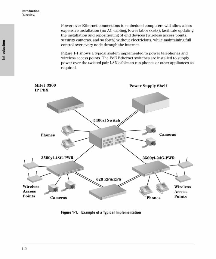
Power over Ethernet connections to embedded computers will allow a less expensive installation (no AC cabling, lower labor costs), facilitate updating the installation and repositioning of end devices (wireless access points, security cameras, and so forth) without electricians, while maintaining full control over every node through the internet.
Figure 1-1 shows a typical system implemented to power telephones and wireless access points. The PoE Ethernet switches are installed to supply power over the twisted pair LAN cables to run phones or other appliances as required.
Figure 1-1. Example of a Typical Implementation
5406zl Switch
3500yl-48G-PWR 3500yl-24G-PWR
Wireless
Access
Points
Cameras
Cameras
Phones
Phones
Mitel 3300
IP PBX
Wireless
Access
Points
620 RPS/EPS
Power Supply Shelf
1-2
IntroductionPower Through the Cable
Introduction
Here are some reasons why you might want to do this:
■ Simplifies installation and saves space - only one set of wires to bring to your appliance.
■ Saves time and money - there is no need to pay for additional electrical power runs or to delay your installation schedule to make them.
■ Minimal disruption to the workplace - the appliance can be easily moved, to wherever you can lay a LAN cable.
■ Safer - no AC voltages need to be added for additional network devices.
■ As well as the data transfer to and from the appliance, you can use SNMP network management infrastructure to monitor and control the appliances.
■ Appliances can be shut down or reset remotely - no need for a reset button or power switch.
■ When implementing wireless LAN systems it simplifies the radio frequency (RF) survey task, as the access point can easily be moved and wired in.
Power Through the Cable
A standard CAT5 Ethernet cable has four twisted pairs, but only two of these pairs are used for 10Base-T and 100Base-TX data and all four are used for 1000Base-T data. The specification allows two options for using these cables for power:
■ The spare pairs are used. The pair on pins 4 and 5 are connected together and form the positive supply, and the pair on pins 7 and 8 are connected and form the negative supply.
■ The data pairs are used. Since Ethernet pairs are transformer coupled at each end, it is possible to apply DC power to the center tap of the isolation transformer without upsetting the data transfer. In this mode of operation the pair on pins 1 and 2 and the pair on pins 3 and 6 can be of either polarity.
The 802.3af standard does not allow both pairs (spare and data) to be used - a choice must be made. The Power Sourcing Equipment (PSE) applies power to either set of wires. ProCurve Networking switches, as a PSE, supply PoE power over the “data pair” or, pins 1 and 2, and the pair on pins 3 and 6. The Powered Device (PD) must be able to accept power from both options because mid-span equipment must (according to the specification) supply power over the “spare pair” or pins 4 and 5, and the pair on pins 7 and 8.
1-3

IntroductionPoE Capabilities of the Products
Intr
oduc
tion
An obvious requirement of the specification is to prevent damage to existing Ethernet equipment. A discovery process, run from the PSE, examines the Ethernet cables, looking for devices that comply with the specification.
It does this by applying a small current-limited voltage to the cable and checks for the presence of a 25k ohm resistor in the remote device. Only if the resistor is present, will the full wattage be applied, but this is still current-limited to prevent damage to cables and equipment in fault conditions.
The PD must continue to draw a minimum current. If it does not (for example, when the device is unplugged) then the PSE removes the power and the discovery process begins again.
PoE Capabilities of the Products
These switch devices are designed to be used primarily in wiring closets directly connected to computers, printers, and servers to provide dedicated bandwidth to those devices. In addition, they support the PoE standard, IEEE 802.3af, and can supply power over a twisted-pair cable to power devices such as telephones and wireless access points.
The ProCurve PoE switch devices are multiport switches that can be used to build high-performance switched workgroup networks with PoE. These switches are store-and-forward devices that offer low latency for high-speed networking. The ProCurve PoE switch devices are designed to support Redundant Power Supply and Power over Ethernet (PoE) technologies.
1-4
IntroductionPoE Capabilities of the Products
Introduction
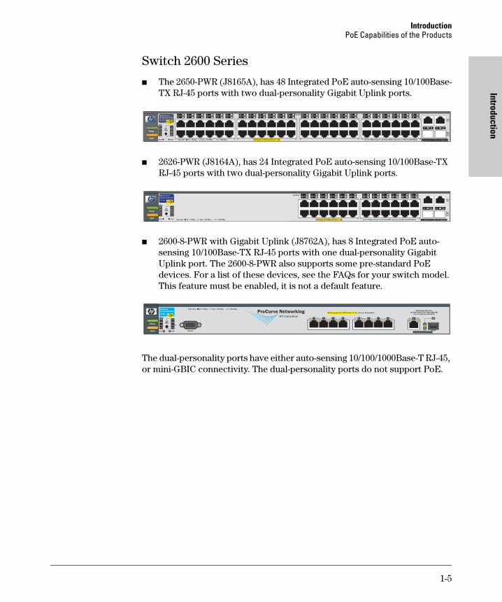
Switch 2600 Series
■ The 2650-PWR (J8165A), has 48 Integrated PoE auto-sensing 10/100Base-TX RJ-45 ports with two dual-personality Gigabit Uplink ports.
■ 2626-PWR (J8164A), has 24 Integrated PoE auto-sensing 10/100Base-TX RJ-45 ports with two dual-personality Gigabit Uplink ports.
■ 2600-8-PWR with Gigabit Uplink (J8762A), has 8 Integrated PoE auto-sensing 10/100Base-TX RJ-45 ports with one dual-personality Gigabit Uplink port. The 2600-8-PWR also supports some pre-standard PoE devices. For a list of these devices, see the FAQs for your switch model. This feature must be enabled, it is not a default feature.
The dual-personality ports have either auto-sensing 10/100/1000Base-T RJ-45, or mini-GBIC connectivity. The dual-personality ports do not support PoE.
���
�����
���
����������������������������������������������������
������ ����������!���� ��� �"�
#���
$���� ����� �������
��������%���&���������"������������'��(�����������)��!���� �"�
�����*�#���+,�-.����/$
0'1.-!
2#3&�4�&�����������55�6�����73�8�����������5��,�6������73�8����������6�������73�
9��:
��&�
9� ��&�
#3&
!+�
� ;
����
��#
��
- < =9��: ��&�� 9��: ��&�> . 1 ' �9��: ��&�
���2
�
� �������� ����������
$�#
1-5
IntroductionPoE Capabilities of the Products
Intr
oduc
tion
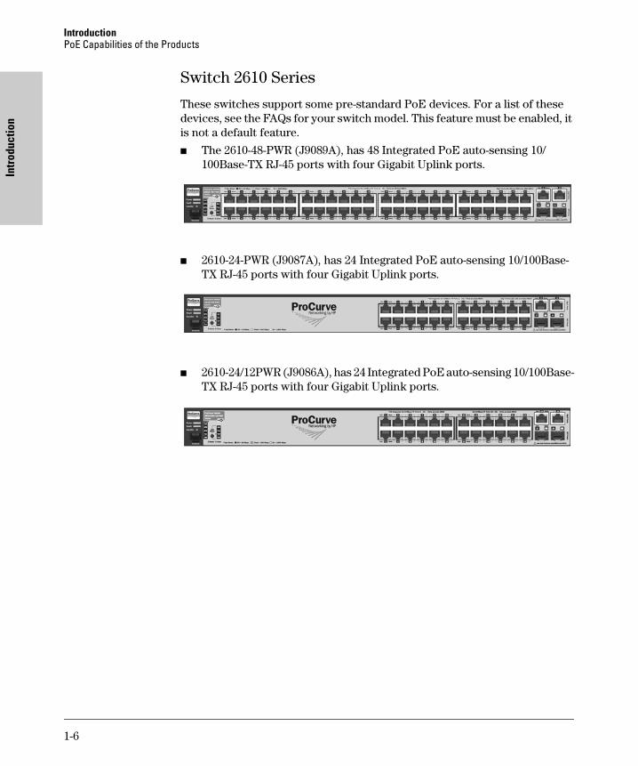
Switch 2610 Series
These switches support some pre-standard PoE devices. For a list of these devices, see the FAQs for your switch model. This feature must be enabled, it is not a default feature.
■ The 2610-48-PWR (J9089A), has 48 Integrated PoE auto-sensing 10/100Base-TX RJ-45 ports with four Gigabit Uplink ports.
■ 2610-24-PWR (J9087A), has 24 Integrated PoE auto-sensing 10/100Base-TX RJ-45 ports with four Gigabit Uplink ports.
■ 2610-24/12PWR (J9086A), has 24 Integrated PoE auto-sensing 10/100Base-TX RJ-45 ports with four Gigabit Uplink ports.
1-6

IntroductionPoE Capabilities of the Products
Introduction
Switch xl PoE Module
■ The ProCurve Switch xl PoE Module (J8161A) is a module for the ProCurve 5300xl Switch and has 24 PoE-Ready auto-sensing 10/100-TX RJ-45 ports.
All 24 ports are capable of supplying PoE power. However, for the module ports to be able to supply PoE power it first must be connected to an EPS port on a ProCurve 600 Redundant and External Power Supply (J8168A), or the ProCurve 610 External Power Supply (J8169A), hereafter referred to as the 600 RPS/EPS or the 610 EPS, respectively.
Power Redundancy for the Switch 2600, 2610 Series and the Switch xl PoE module (J8161A)
The internal power supply in these switches provides both the 12V (RPS) and 50V (EPS) circuits. If either the 12V or 50V fails, the power supply shuts down which will bring down all switch and PoE connections. Therefore it is important to provide a redundant power supply for both the 12V and 50V circuits. Thus when you connect EPS from a 600 RPS/EPS device to one of the 2600-PWR Series or one of the 2610-PWR Series, you should also connect the RPS as well to provide full redundant power.
The Switch 2600-PWR Series and 2610-PWR Series can be connected to a 600 RPS/EPS and receive full redundant power from the RPS part of the unit for switch operation, if the internal power supply in the switch fails. If multiple switches are connected to the RPS ports and several switches lose power at the same time, the switch attached to the lowest RPS port number receives power. The 600 RPS/EPS unit can provide all the power necessary to keep one switch running.
EPS power from the 600 RPS/EPS is the PoE capability of the device. It supplies backup and additional PoE power for the ports of the 2600-PWR and 2610-PWR switches. It also provides PoE power to the ProCurve Switch xl PoE Module.
The 610 EPS can also be used for this purpose, to supply PoE power only. The 610 EPS cannot supply RPS power, it can only supply PoE power. Refer to chapter three, four, and five for more information on capabilities and connectivity of these switches, components and accessories.
��� ���� ���������������
���� ��� ���� ���� � � ! " �� � �! �" �# �$
�������%�������%�$#
��&'�����%(�%%&�)���� �&� �*���+������,�-��&��.)
�
/+���������
�� ������������
0�1����
��
1-7
IntroductionPoE Capabilities of the Products
Intr
oduc
tion
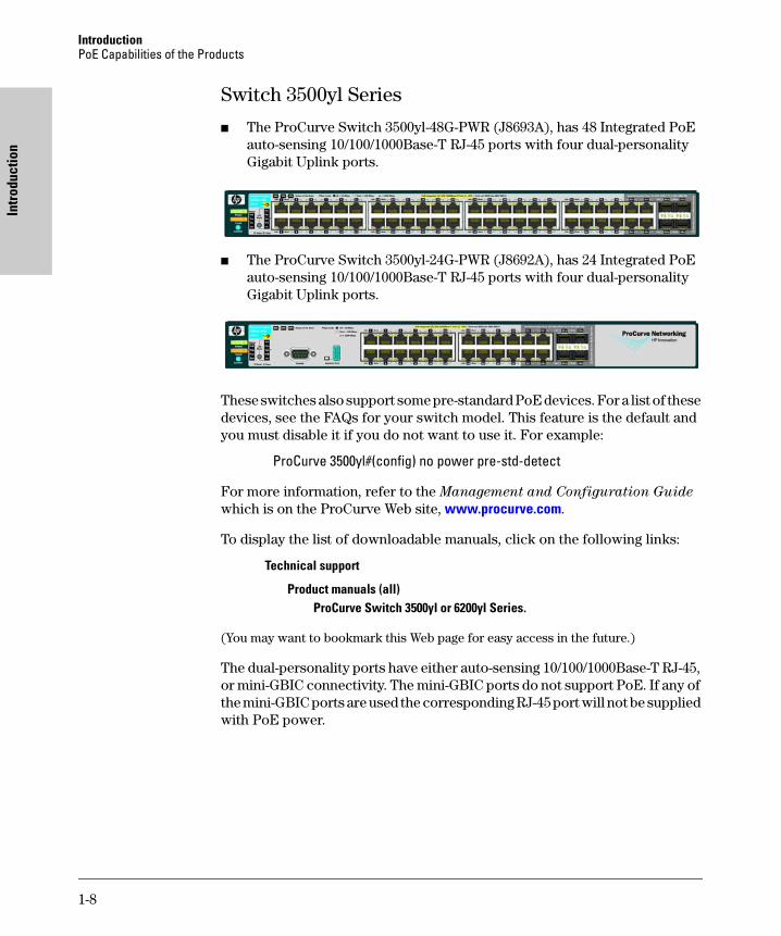
Switch 3500yl Series
■ The ProCurve Switch 3500yl-48G-PWR (J8693A), has 48 Integrated PoE auto-sensing 10/100/1000Base-T RJ-45 ports with four dual-personality Gigabit Uplink ports.
■ The ProCurve Switch 3500yl-24G-PWR (J8692A), has 24 Integrated PoE auto-sensing 10/100/1000Base-T RJ-45 ports with four dual-personality Gigabit Uplink ports.
These switches also support some pre-standard PoE devices. For a list of these devices, see the FAQs for your switch model. This feature is the default and you must disable it if you do not want to use it. For example:
ProCurve 3500yl#(config) no power pre-std-detect
For more information, refer to the Management and Configuration Guide which is on the ProCurve Web site, www.procurve.com.
To display the list of downloadable manuals, click on the following links:
Technical support
Product manuals (all) ProCurve Switch 3500yl or 6200yl Series.
(You may want to bookmark this Web page for easy access in the future.)
The dual-personality ports have either auto-sensing 10/100/1000Base-T RJ-45, or mini-GBIC connectivity. The mini-GBIC ports do not support PoE. If any of the mini-GBIC ports are used the corresponding RJ-45 port will not be supplied with PoE power.
1-8

IntroductionPoE Capabilities of the Products
Introduction
Power Redundancy for the Switch 3500yl Series
The internal power supply in these switches provides both the 12V (RPS) and 50V (EPS) circuits. If the 50V portion of the power supply fails, it will only shut down the PoE connections. However, if the 12V portion of the power supply fails, it will shut down the entire switch. Therefore it is important to provide a redundant power supply for both the 12V and 50V circuits. Therefore it is recommended that both EPS and RPS be connected to provide full redundancy.
The Switch 3500yl-PWR Series can be connected to a 620 RPS/EPS and receive full redundant power from the RPS part of the unit for switch operation, if the internal power supply in the switch fails. If two switches are connected to the RPS ports and both switches lose power at the same time, they both receive redundant power. The 620 RPS/EPS unit can provide all the power necessary to keep two switches running.
If maximum PoE power is to be used on all 48 ports, it becomes necessary to connect a 620 RPS/EPS, since the internal power supply only has enough power to supply 24 ports with maximum wattage. In this case, there is no redundancy.
1-9
IntroductionPoE Capabilities of the Products
Intr
oduc
tion
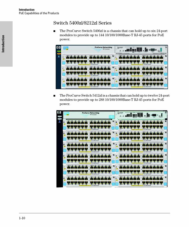
Switch 5400zl/8212zl Series
■ The ProCurve Switch 5406zl is a chassis that can hold up to six 24-port modules to provide up to 144 10/100/1000Base-T RJ-45 ports for PoE power.
■ The ProCurve Switch 5412zl is a chassis that can hold up to twelve 24-port modules to provide up to 288 10/100/1000Base-T RJ-45 ports for PoE power.
1-10
IntroductionPoE Capabilities of the Products
Introduction
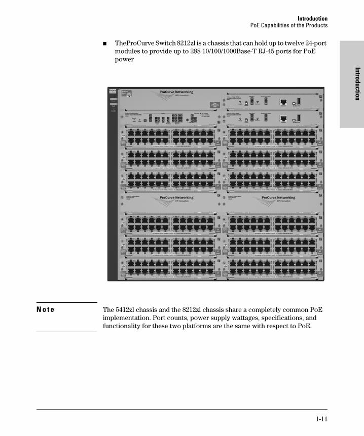
■ TheProCurve Switch 8212zl is a chassis that can hold up to twelve 24-port modules to provide up to 288 10/100/1000Base-T RJ-45 ports for PoE power
N o t e The 5412zl chassis and the 8212zl chassis share a completely common PoE implementation. Port counts, power supply wattages, specifications, and functionality for these two platforms are the same with respect to PoE.
1-11

IntroductionPoE Capabilities of the Products
Intr
oduc
tion
Power Redundancy for the 5406zl, 5412zl, and 8212zl
There are two types of power supplied by the Series 5400zl/8200zl switch power supplies:
■ 12V power or system power
■ 50V power or PoE power
The 12V system power is used to operate the internal components of the switch. The 50V PoE power is used to power the PoE devices connected to the modules.
It is important to provide a secondary power supply for redundancy purposes for both the 12V and 50V circuits. The internal power supply in these switches provides both the 12V (system) and 50V (PoE) circuits. If the 12V (system) power fails the switch will shut down. If the 50V (PoE) fails, all PDs would lose power. Therefore, to keep the switch running should one power supply, or either power source fail, you should install a second power supply.
The 5406zl chassis can hold two internal power supplies and the 5412zl/8212zl chassis can hold four internal power supplies:
■ J8712A, which operates at 100-127 volts drawing a maximum of 11.5 amps, or 200-240 volts drawing a maximum of 5.7 amps, and supplies 273 watts of PoE power
■ J8713A, which operates at 200-220 volts drawing a maximum of 10 amps, and supplies 900 watts of PoE power
Using two J8712As, or two J8713As, or a mix of both is supported (however mixing power supplies is not recommended, see page 7-8 for more information) and necessary to ensure the switch has both 12V (system power) and 50V (PoE power) should one power supply fail. See the ProCurve Switch
zl Internal Power Supplies Installation Guide, for more information and specifications on these power supplies.
When considering redundant power, also consider the power source for the power supplies. Each power supply should be connected to a separate power source circuit in order to supply complete redundancy. Should one circuit fail, it would then be possible for the other circuit to continue supplying power to the second power supply in the switch, keeping the switch running.
There is also an external power supply, the ProCurve Switch zl Power Supply Shelf (J8714A), that can be connected to either the 5400zl switches or the 8200zl switch for the purpose of adding extra or backup 50V (PoE power). The zl Power Supply Shelf will not supply any 12V (system power) to any zl switch, since the switch is provided with 12V redundancy when more than one power supply is installed in the chassis.
1-12
IntroductionPoE Capabilities of the Products
Introduction
Configuring PoE Redundancy
When PoE redundancy is enabled, PoE redundancy occurs automatically. The switch keeps track of power use and won’t supply PoE power to additional PoE devices trying to connect if that results in the switch not having enough power in reserve for redundancy if one of the power supplies should fail. There are three configurable redundancy methods:
■ No PoE redundancy enforcement (default). All available power can be allocated.
■ Full redundancy: half of the totally available PoE power can be allocated and half is held in reserve for redundancy. If power supplies with different ratings are used, the highest-rated power supply is held in reserve to ensure full redundancy.
■ N+1. One of the power supplies is held in reserve for redundancy. If a single power supply fails, no powered devices are shut down. If power supplies with different ratings are used, the highest-rated power supply is held in reserve to ensure full redundancy.
N o t e When changing from one method to another, always check the current level of PoE usage before implementing the change. The change could cause existing connection to loose PoE power.
For more information refer to the Management and Configuration Guide for your switch.
1-13
IntroductionPoE Capabilities of the Products
Intr
oduc
tion
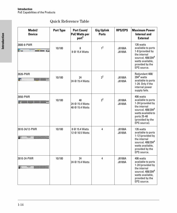
Quick Reference Table
Model/Device
Port Type Port Count/PoE Watts per
port1
Gig Uplink Ports
RPS/EPS Maximum Power Internal and
External
2600-8-PWR10/100 8
8 @ 15.4 Watts12 J8168A
J8169A
126 watts available to ports 1-8 (provided by the internal source). 408/2044 watts available, provided by the EPS source.
2626-PWR10/100 24
24 @ 15.4 Watts22 J8168A
J8169A
Redundant 408/2044 watts available to ports 1-24. Only if the internal power supply fails.
2650-PWR10/100 48
24 @ 15.4 Watts48 @ 15.4 Watts
22 J8168AJ8169A
406 watts available to ports 1-24 (provided by the internal source). 408/2044 watts available to ports 25-48 (provided by the EPS source).
2610-24/12-PWR 10/100 8 @ 15.4 Watts12 @ 10.5 Watts
4 J8168AJ8169A
126 watts available to ports 1-12 (provided by the internal source). 408/2044 watts available, provided by the EPS source.
2610-24-PWR 10/100 2424 @ 15.4 Watts
4 J8168AJ8169A
406 watts available to ports 1-24 (provided by the internal source). 408/2044 watts available, provided by the EPS source.
���
���
��
����������������������������������������������������
������ ����������!���� ��� �"�
#���
$���� ����� �������
��������%���&���������"������������'��(�����������)��!���� �"�
�����*�#���+,�-.����/$
0'1.-!
2#3&�4�&�����������55�6�����73�8�����������5��,�6������73�8����������6�������73�
9��:
��&�
9� ��&�
#3&
!+�
� ;
����
��#
��
- < =9��: ��&�� 9��: ��&�> . 1 ' �9��: ��&�
���2
�
� �������� ����������
$�#
1-14
IntroductionPoE Capabilities of the Products
Introduction
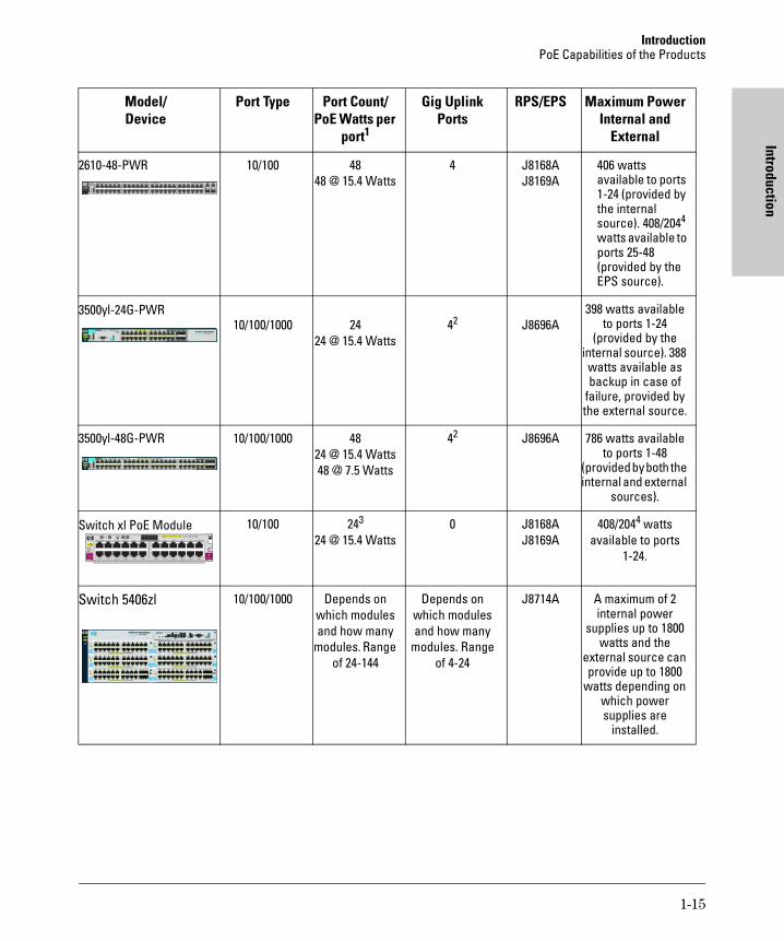
2610-48-PWR 10/100 4848 @ 15.4 Watts
4 J8168AJ8169A
406 watts available to ports 1-24 (provided by the internal source). 408/2044 watts available to ports 25-48 (provided by the EPS source).
3500yl-24G-PWR10/100/1000 24
24 @ 15.4 Watts42 J8696A
398 watts available to ports 1-24
(provided by the internal source). 388 watts available as backup in case of
failure, provided by the external source.
3500yl-48G-PWR 10/100/1000 4824 @ 15.4 Watts48 @ 7.5 Watts
42 J8696A 786 watts available to ports 1-48
(provided by both the internal and external
sources).
Switch xl PoE Module 10/100 243
24 @ 15.4 Watts0 J8168A
J8169A408/2044 watts
available to ports 1-24.
Switch 5406zl 10/100/1000 Depends on which modules and how many
modules. Range of 24-144
Depends on which modules and how many
modules. Range of 4-24
J8714A A maximum of 2 internal power
supplies up to 1800 watts and the
external source can provide up to 1800
watts depending on which power supplies are
installed.
Model/Device
Port Type Port Count/PoE Watts per
port1
Gig Uplink Ports
RPS/EPS Maximum Power Internal and
External
��� ���� ���������������
���� ��� ���� ���� � � ! " �� � �! �" �# �$
�������%�������%�$#
��&'�����%(�%%&�)���� �&� �*���+������,�-��&��.)
�
/+���������
�� ������������
0�1����
��
1-15
IntroductionPoE Capabilities of the Products
Intr
oduc
tion
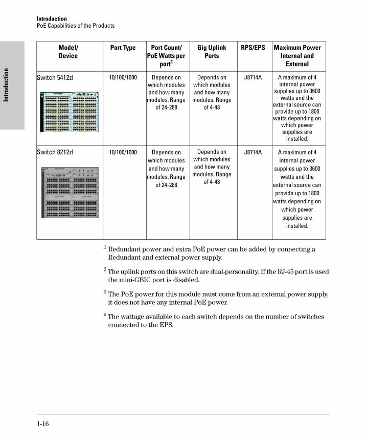
1 Redundant power and extra PoE power can be added by connecting a Redundant and external power supply.
2 The uplink ports on this switch are dual-personality. If the RJ-45 port is used the mini-GBIC port is disabled.
3 The PoE power for this module must come from an external power supply, it does not have any internal PoE power.
4 The wattage available to each switch depends on the number of switches connected to the EPS.
Switch 5412zl 10/100/1000 Depends on which modules and how many
modules. Range of 24-288
Depends on which modules and how many
modules. Range of 4-48
J8714A A maximum of 4 internal power
supplies up to 3600 watts and the
external source can provide up to 1800
watts depending on which power supplies are
installed.
Switch 8212zl 10/100/1000 Depends on which modules and how many
modules. Range of 24-288
Depends on which modules and how many
modules. Range of 4-48
J8714A A maximum of 4 internal power
supplies up to 3600 watts and the
external source can provide up to 1800
watts depending on which power supplies are
installed.
Model/Device
Port Type Port Count/PoE Watts per
port1
Gig Uplink Ports
RPS/EPS Maximum Power Internal and
External
1-16
Operating Rules
2
Operating Rules
This chapter discusses the operating rules and characteristics of the ProCurve product capabilities, switches and external power supplies. The following products are discussed:
■ The ProCurve Switch 2600-PWR Series.
■ The ProCurve Switch 2610-PWR Series.
■ The ProCurve Redundant and External Power Supplies: 600 RPS/EPS and 610 EPS.
■ The ProCurve Switch 3500yl-PWR Series.
■ The ProCurve External and Redundant Power Supply, 620 RPS/EPS.
■ The ProCurve Switch 5400/8212zl Series.
■ The ProCurve Power Supply Shelf.
Switch PoE OperationThe Switch 2626-PWR provisions (allocates power to) ports 1-24 with 406 watts of power for PoE applications compatible with the IEEE 802.3af standard. The Switch 2650-PWR provisions ports 1-48 with 406 watts. This reduces the per port wattage by half as compared to the Switch 2626-PWR.
The Switch 2610-24/12PWR provisions (allocates power to) ports 1-12 with 126 watts of power for PoE applications compatible with the IEEE 802.3af standard. The Switch 2610-24-PWR provisions ports 1-24 with 406 watts and the Switch 2610-48-PWR provisions ports 1-48 with 406 watts. This reduces the per port wattage by half as compared to the Switch 2610-24-PWR.
The Switch 3500yl-24G-PWR can supply up to 398 Watts of PoE power across the 24 ports. The Switch 3500yl-48G-PWR can supply up to 398 Watts of PoE power across the 48 ports.
The Switch 5406zl can supply up to 1800 watts of PoE power and the Switch 5412zl/8212zl can supply up to 3600 watts of PoE power. It depends on which power supply is installed. The J8712A power supply provides up to 273 watts of PoE power. If two J8712As are installed they can supply up to 546 watts of PoE power and if four are installed they can supply up to 1092 watts of PoE power.
2-1
Operating RulesProvisioning Power for PoE
Ope
ratin
g Ru
les
The J8713A power supply provides up to 900 watts of PoE power. If two J8713As are installed they can supply up to 1800 watts of PoE power and if four are installed they can supply up to 3600 watts of PoE power. The two types of power supplies can be mixed (although not recommended), that is, one or two J8712As and one or two J8713As can be installed at the same time depending on which of the Series 5400zl/8200zl Switches are being used.
N o t e ProCurve Networking highly recommends that the two types of power supplies are not mixed in the same 5400zl/8200zl chassis or Power Supply Shelf. See page 7-8 for more information.
Provisioning Power for PoE
All of these PoE switches support an external power supply that can provide either redundant or extra PoE power. It is important to understand how PoE power is provisioned in order to use these external power supplies efficiently. The following chapters will discuss this in detail.
By connecting an external power supply you can optionally provision more PoE wattage per port and or supply the switch with redundant 12V power to operate should an internal power supply fail.
By installing a second power supply in the 5406zl or a third power supply in a 5412zl/8212zl chassis, depending on how many PoE ports are being supplied with power, the switch can have redundant power if one power supply fails. A Power Supply Shelf (external power supply) can also be connected to the 5400zl/8200zl switches to provide extra or redundant PoE power.
For example, if the 5406zl has two 24-port PoE modules (J8702A) installed, and all ports are using 15.4 watts, then the total wattage used is 739.2 watts (48 x 15.4). Therefore to supply the necessary PoE wattage a J8713A power supply is installed in one of the power supply slots. Then to gain redundant power a second J8713A must be installed in the second power supply slot. If the first power supply fails, then the second power supply can supply all necessary power.
2-2

Operating RulesProvisioning Power for PoE
Operating Rules
There is a CLI command available, the THRESHOLD command. It has an informational only result. This command sets a threshold, by percent, to inform you the switch is now using more than a certain percentage of PoE power.
For example if the threshold is set at 50%, the switch will issue an information message informing you the switch has exceeded the threshold when 51% of available PoE power is being used. Also see page 7-7 for an example. For more information on the threshold command, Refer to the Management and
Configuration Guide which is on the ProCurve Web site, www.procurve.com. (See page 1-8 for details.)
Maximum PoE Power
Switch 2600-PWR Series
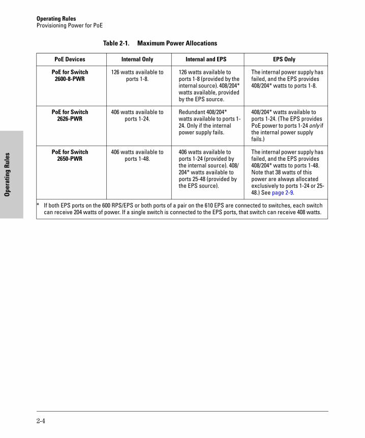
The Switch 2600-8-PWR provisions (allocates power to) 8 ports with its internal PoE power supply of 126 watts for PoE applications compatible with the IEEE 802.3af standard and some pre-standard PoE devices.The Switch 2626-PWR provisions ports 1-24 with 406 watts of power for PoE applications compatible with the IEEE 802.3af standard. The Switch 2650-PWR provisions ports 1-48 with 406 watts for PoE. This reduces the per port wattage by half as compared to the Switch 2626-PWR.
However, by connecting a 600 RPS/EPS or a 610 EPS, you can optionally provision ports 25-48 with 408 watts of external PoE power, thereby bringing the per port wattage up to 15.4 watts per port, unless you have the other EPS port of the 600 RPS/EPS or the other port of a pair on the 610 EPS connected to a ProCurve PoE device. In this case you cannot provision the full 408 watts to the Switch 2650-PWR, only half, or 204 watts.
2-3
Operating RulesProvisioning Power for PoE
Ope
ratin
g Ru
les
Table 2-1. Maximum Power Allocations
PoE Devices Internal Only Internal and EPS EPS Only
PoE for Switch 2600-8-PWR
126 watts available to ports 1-8.
126 watts available to ports 1-8 (provided by the internal source). 408/204* watts available, provided by the EPS source.
The internal power supply has failed, and the EPS provides 408/204* watts to ports 1-8.
PoE for Switch 2626-PWR
406 watts available to ports 1-24.
Redundant 408/204* watts available to ports 1-24. Only if the internal power supply fails.
408/204* watts available to ports 1-24. (The EPS provides PoE power to ports 1-24 only if the internal power supply fails.)
PoE for Switch 2650-PWR
406 watts available to ports 1-48.
406 watts available to ports 1-24 (provided by the internal source). 408/204* watts available to ports 25-48 (provided by the EPS source).
The internal power supply has failed, and the EPS provides 408/204* watts to ports 1-48. Note that 38 watts of this power are always allocated exclusively to ports 1-24 or 25-48.) See page 2-9.
* If both EPS ports on the 600 RPS/EPS or both ports of a pair on the 610 EPS are connected to switches, each switch can receive 204 watts of power. If a single switch is connected to the EPS ports, that switch can receive 408 watts.
2-4
Operating RulesProvisioning Power for PoE
Operating Rules
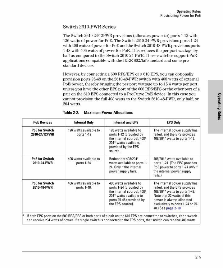
Switch 2610-PWR Series
The Switch 2610-24/12PWR provisions (allocates power to) ports 1-12 with 126 watts of power for PoE. The Switch 2610-24-PWR provisions ports 1-24 with 406 watts of power for PoE and the Switch 2610-48-PWR provisions ports 1-48 with 406 watts of power for PoE. This reduces the per port wattage by half as compared to the Switch 2610-24-PWR. These switches support PoE applications compatible with the IEEE 802.3af standard and some pre-standard devices.
However, by connecting a 600 RPS/EPS or a 610 EPS, you can optionally provision ports 25-48 on the 2610-48-PWR switch with 408 watts of external PoE power, thereby bringing the per port wattage up to 15.4 watts per port, unless you have the other EPS port of the 600 RPS/EPS or the other port of a pair on the 610 EPS connected to a ProCurve PoE device. In this case you cannot provision the full 408 watts to the Switch 2610-48-PWR, only half, or 204 watts.
Table 2-2. Maximum Power Allocations
PoE Devices Internal Only Internal and EPS EPS Only
PoE for Switch 2610-24/12PWR
126 watts available to ports 1-12
126 watts available to ports 1-12 (provided by the internal source). 408/204* watts available, provided by the EPS source.
The internal power supply has failed, and the EPS provides 408/204* watts to ports 1-12.
PoE for Switch 2610-24-PWR
406 watts available to ports 1-24.
Redundant 408/204* watts available to ports 1-24. Only if the internal power supply fails.
408/204* watts available to ports 1-24. (The EPS provides PoE power to ports 1-24 only if the internal power supply fails.)
PoE for Switch 2610-48-PWR
406 watts available to ports 1-48.
406 watts available to ports 1-24 (provided by the internal source). 408/204* watts available to ports 25-48 (provided by the EPS source).
The internal power supply has failed, and the EPS provides 408/204* watts to ports 1-48. Note that 22 watts of this power is always allocated exclusively to ports 1-24 or 25-48.) See page 2-10.
* If both EPS ports on the 600 RPS/EPS or both ports of a pair on the 610 EPS are connected to switches, each switch can receive 204 watts of power. If a single switch is connected to the EPS ports, that switch can receive 408 watts.
2-5
Operating RulesProvisioning Power for PoE
Ope
ratin
g Ru
les
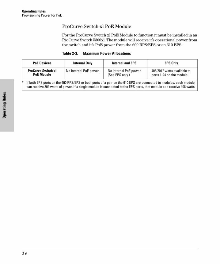
ProCurve Switch xl PoE Module
For the ProCurve Switch xl PoE Module to function it must be installed in an ProCurve Switch 5300xl. The module will receive it’s operational power from the switch and it’s PoE power from the 600 RPS/EPS or an 610 EPS.
Table 2-3. Maximum Power Allocations
PoE Devices Internal Only Internal and EPS EPS Only
ProCurve Switch xl PoE Module
No internal PoE power. No internal PoE power. (See EPS only.)
408/204* watts available to ports 1-24 on the module.
* If both EPS ports on the 600 RPS/EPS or both ports of a pair on the 610 EPS are connected to modules, each module can receive 204 watts of power. If a single module is connected to the EPS ports, that module can receive 408 watts.
2-6
Operating RulesProvisioning Power for PoE
Operating Rules
Switch 3500yl PWR Series
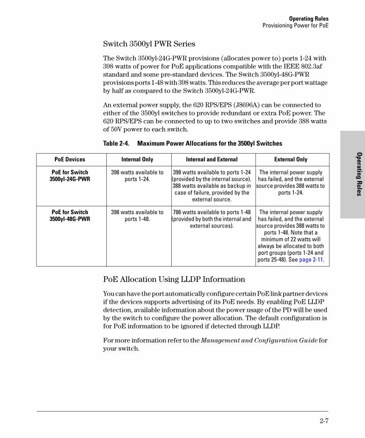
The Switch 3500yl-24G-PWR provisions (allocates power to) ports 1-24 with 398 watts of power for PoE applications compatible with the IEEE 802.3af standard and some pre-standard devices. The Switch 3500yl-48G-PWR provisions ports 1-48 with 398 watts. This reduces the average per port wattage by half as compared to the Switch 3500yl-24G-PWR.
An external power supply, the 620 RPS/EPS (J8696A) can be connected to either of the 3500yl switches to provide redundant or extra PoE power. The 620 RPS/EPS can be connected to up to two switches and provide 388 watts of 50V power to each switch.
Table 2-4. Maximum Power Allocations for the 3500yl Switches
PoE Allocation Using LLDP Information
You can have the port automatically configure certain PoE link partner devices if the devices supports advertising of its PoE needs. By enabling PoE LLDP detection, available information about the power usage of the PD will be used by the switch to configure the power allocation. The default configuration is for PoE information to be ignored if detected through LLDP.
For more information refer to the Management and Configuration Guide for your switch.
PoE Devices Internal Only Internal and External External Only
PoE for Switch 3500yl-24G-PWR
398 watts available to ports 1-24.
398 watts available to ports 1-24 (provided by the internal source). 388 watts available as backup in case of failure, provided by the
external source.
The internal power supply has failed, and the external
source provides 388 watts to ports 1-24.
PoE for Switch 3500yl-48G-PWR
398 watts available to ports 1-48.
786 watts available to ports 1-48 (provided by both the internal and
external sources).
The internal power supply has failed, and the external
source provides 388 watts to ports 1-48. Note that a
minimum of 22 watts will always be allocated to both port groups (ports 1-24 and ports 25-48). See page 2-11.
2-7
Operating RulesProvisioning Power for PoE
Ope
ratin
g Ru
les
The Switch 5400zl/8212zl Series
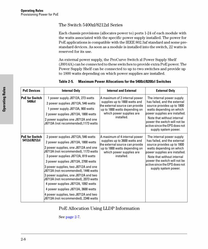
Each chassis provisions (allocates power to) ports 1-24 of each module with the watts associated with the specific power supply installed. The power for PoE applications is compatible with the IEEE 802.3af standard and some pre-standard devices. As soon as a module is installed into the switch, 22 watts is reserved for its use.
An external power supply, the ProCurve Switch zl Power Supply Shelf (J8914A) can be connected to these switches to provide extra PoE power. The Power Supply Shelf can be connected to up to two switches and provide up to 1800 watts depending on which power supplies are installed.
Table 2-5. Maximum Power Allocations for the 5400zl/8200zl Switches
PoE Allocation Using LLDP Information
See page 2-7.
PoE Devices Internal Only Internal and External External Only
PoE for Switch5406zl
1 power supply J8712A, 273 watts2 power supplies J8712A, 546 watts
1 power supply J8713A, 900 watts
2 power supplies J8713A, 1800 watts2 power supplies one J8712A and one J8713A (not recommended),1173 watts
A maximum of 2 internal power supplies up to 1800 watts and
the external source can provide up to 1800 watts depending on
which power supplies are installed.
The internal power supply has failed, and the external source provides up to 1800 watts depending on which
power supplies are installed.Note that without internal
power the switch will not be active since the EPS does not
supply system power.
PoE for Switch5412zl/8212zl
2 power supplies J8712A, 546 watts
2 power supplies J8713A, 1800 watts
2 power supplies, one J8712A and one J8713A (not recommended), 1173 watts
3 power supplies J8712A, 819 watts
3 power supplies J8713A, 2700 watts3 power supplies, two J8712A and one J8713A (not recommended), 1446 watts3 power supplies, one J8712A and two J8713A (not recommended), 2073 watts
4 power supplies J8712A, 1092 watts
4 power supplies J8713A, 3600 watts4 power supplies, two J8712A and two J8713A (not recommended), 2346 watts
A maximum of 4 internal power supplies up to 3600 watts and
the external source can provide up to 1800 watts depending on
which power supplies are installed.
The internal power supply has failed, and the external source provides up to 1800 watts depending on which
power supplies are installed.Note that without internal
power the switch will not be active since the EPS does not
supply system power.
2-8

Operating RulesProvisioning Power for PoE
Operating Rules
PoE Power
It is important to understand the PoE power requirements of these switches because if the PoE power is not planned and implemented correctly, end devices connected to the PoE switch ports may not receive power if a switch PoE power source failure occurs or if the switch is over provisioned.
Switch 2600-PWR Series
The Switch 2600-8-PWR has 8 ports and its internal PoE power supply provides 126 watts across all 8 ports. If a 600 RPS/EPS or a 610 EPS device is connected to the Switch 2600-8-PWR for the purpose of supplying external power to the PoE portion of the switch, there will be either 408 watts or 204 watts of power available should the switch’s internal PoE power supply fail. If a single switch is connected to the EPS ports on the 600 RPS/EPS or a single port of a pair on the 610 EPS, 408 watts are available, providing fully redundant PoE power to the switch. If two switch devices are connected to the EPS ports on the 600 RPS/EPS or to both ports of a pair on the 610 EPS, only 204 watts are provided to the switch if the internal PoE power supply fails. This will still provide enough wattage to be a full PoE backup for the Switch 2600-8-PWR because it only needs 126 watts.
The Switch 2626-PWR has 24 ports and its internal PoE power supply provides 406 watts across all 24 ports. If a 600 RPS/EPS or a 610 EPS device is connected to the Switch 2626-PWR for the purpose of supplying external power to the PoE portion of the switch, there will be either 408 watts or 204 watts of power available should the switch’s internal PoE power supply fail. If a single switch is connected to the EPS ports on the 600 RPS/EPS or a single port of a pair on the 610 EPS, 408 watts are available, providing fully redundant PoE power to the switch. If two switch devices are connected to the EPS ports on the 600 RPS/EPS or to both ports of a pair on the 610 EPS, only 204 watts are provided to the switch if the internal PoE power supply fails.
The Switch 2650-PWR PoE power requirements are different. This switch has 48 ports and the internal PoE power supply supplies 406 watts across all 48 ports. The switch reserves 38 watts for either ports 1-24 or 25-48, so that neither set of ports receives the entire 406 watts.
By connecting a 600 RPS/EPS or a 610 EPS to the Switch 2650-PWR, more PoE power is provided to the switch. With the 600 RPS/EPS or the 610 EPS connected to the Switch 2650-PWR, the internal PoE power supply provides the first 24 ports (1-24) with 406 watts and the 600 RPS/EPS or the 610 EPS supplies the second 24 ports (25-48) with 408 or 204 watts (408 watts if only one switch is connected to the EPS ports; 204 watts if two switches are connected to the EPS ports). If the internal PoE power supply in the 2650-PWR switch fails, 408 watts or 204 watts are provided to ports 1-48. 38 watts of power are always allocated to ports 1-25 or 25-48.
2-9

Operating RulesProvisioning Power for PoE
Ope
ratin
g Ru
les
Switch 2610-PWR Series
The Switch 2610-24/12PWR has 24 ports of which 1-12 can be used for PoE and its internal PoE power supply provides 126 watts across 12 ports. If a 600 RPS/EPS or a 610 EPS device is connected to the Switch 2610-24/12PWR for the purpose of supplying external power to the PoE portion of the switch, there will be either 408 watts or 204 watts of power available should the switch’s internal PoE power supply fail. If a single switch is connected to the EPS ports on the 600 RPS/EPS or a single port of a pair on the 610 EPS, 408 watts are available, providing fully redundant PoE power to the switch. If two switch devices are connected to the EPS ports on the 600 RPS/EPS or to both ports of a pair on the 610 EPS, only 204 watts are provided to the switch if the internal PoE power supply fails. This will still provide enough wattage to be a full PoE backup for the Switch 2610-24/12PWR because it only needs 126 watts.
The Switch 2610-24-PWR has 24 ports and its internal PoE power supply provides 406 watts across all 24 ports. If a 600 RPS/EPS or a 610 EPS device is connected to the Switch 2610-24-PWR for the purpose of supplying external power to the PoE portion of the switch, there will be either 408 or 204 watts of power available should the switch’s internal PoE power supply fail. If a single switch is connected to the EPS ports on the 600 RPS/EPS or a single port of a pair on the 610 EPS, 408 watts are available, providing fully redundant PoE power to the switch. If two switch devices are connected to the EPS ports on the 600 RPS/EPS or to both ports of a pair on the 610 EPS, only 204 watts are provided to the switch if the internal PoE power supply fails.
The Switch 2610-48-PWR PoE power requirements are different. This switch has 48 ports and the internal PoE power supply supplies 406 watts across all 48 ports. The switch reserves 22 watts for either ports 1-24 or 25-48, so that neither set of ports receives the entire 406 watts.
By connecting a 600 RPS/EPS or a 610 EPS to the Switch 2610-48-PWR, more PoE power is provided to the switch. With the 600 RPS/EPS or the 610 EPS connected to the Switch 2610-48-PWR, the internal PoE power supply provides the first 24 ports (1-24) with 406 watts and the 600 RPS/EPS or the 610 EPS supplies the second 24 ports (25-48) with 408 or 204 watts (408 watts if only one switch is connected to the EPS ports; 204 watts if two switches are connected to the EPS ports). If the internal PoE power supply in the 2610-48-PWR switch fails, 408 watts or 204 watts are provided to ports 1-48. 22 watts of power are always allocated to ports 1-25 or 25-48. See page 4-7.
2-10

Operating RulesProvisioning Power for PoE
Operating Rules
Switch 3500yl PWR Series
The Switch 3500yl-24G-PWR has 24 ports with an internal PoE power supply that provides 398 watts of 50V power across all 24 ports. The Switch 3500yl-48G-PWR has 48 ports with 398 watts of 50V power across all 48 ports. There is a special power provision on the Switch 3500yl-48G-PWR, Where the switch reserves 22 watts for each bank of 24 ports, ports 1-24 and 25-48, so that neither set of ports receives the entire 398 watts. This is designed for the integrity and safety of PoE during power balancing to properly detect PDs and bring them online.
Switch 5400zl/8212zl Series
There are two PoE modules (J8702A and J8705A) for the 5400zl/8212zl chassis and they have the same requirement for reserving 22 watts (see above). There are 22 watts per module that is always held in reserve.
Each group of 24 ports is it's own management group and needs to have a minimum allocation associated with it in order to properly detect PDs and bring them online.
Remember that each group of 24 ports will have a PoE power allocation of at least 22 watts. This 22 watts must be subtracted from the total wattage when figuring how many PoE devices to connect to which ports on a switch or module. In order to be able to allocate the reserved 22 watts, either use the ports it is allocated to or the PoE power to all ports on the associated module must be turned off, refer to the Management and Configuration Guide which is on the ProCurve Web site, www.procurve.com, for details. (See page 1-8.)
Allocate PoE Power by Class or User-defined Power Level.
The Switch 3500yl and the 5400zl/8212zl switches provide maximum flexibility by allowing the switch to detect and display 802.3af device class, but does not enforce the power level specified in each device class. In addition to this, the switch can allocate PoE power according to the power level specified in each device class or a level defined by the customer. There are three methods to allocate PoE power:
■ By device usage (default). The switch does not enforce the power limit.
■ By power level specified in 802.3af. The device class will be detected according to the specification and power limits will be enforced.
■ By user-defined. Configurable per port values or a range of ports to power level 1-17 watts. Incorrectly setting the PoE maximum value to be less than the device requires will result in a PoE fault.
For more information refer to the Management and Configuration Guide for your switch.
2-11
Operating RulesProvisioning Power for PoE
Ope
ratin
g Ru
les
Switch Port Priority
The lower the port number the higher the priority given. For example, port number one has a higher priority than port number two. Therefore when both ports need power, port number one is given power priority over port number two and so on throughout the rest of the ports.
A port can be assigned a power priority that alters the assignment of power to it by the switch. See the Management and Configuration Guide which is on the ProCurve Web site, www.procurve.com, for details. (See page 1-8.)
Switch Priority Class
Port priority classification can be used by the switch to allocate power to ports. It is a prioritization scheme by which the user can assign a low (default), high, or critical priority to any given port. This assignment is done through the command line interface (see the Management and Configuration Guide which is on the ProCurve Web site, www.procurve.com (See page 1-8.)), of the switch and alters the hardware port-number priority for power allocation.
■ Low (default) - This priority class receives power only if all other priority classes are receiving power. If there is enough power to provision PDs on only some of the ports with a low priority, then power is allocated to the ports in ascending order, beginning with the lowest-numbered port in the class until all available power is in use.
■ High - This priority class receives power only if all PDs on ports assigned with a critical priority are receiving full power. If there is not enough power to provision PDs on ports assigned with a high priority, then no power goes to the low priority ports. If there is enough power to provision PDs on only some of the high priority ports, then power is allocated to the high priority ports in ascending order, beginning with lowest-numbered high priority port, until all available power is in use.
■ Critical - This priority class is the first to be allocated power. If there is not enough power to provision PDs on all of the ports configured for this class, then no power goes to “High or Low” priority ports. If there is enough power to provision PDs on only some of the critical ports, then power is allocated to the critical ports in ascending order, beginning with the lowest-numbered port in the class.
2-12
Operating RulesProvisioning Power for PoE
Operating Rules
Line Loss
A certain amount of power is consumed by the resistance of the wire in the LAN cable connected from the switch to the powered device (typically less than 16% loss), which can be influenced by cable length, quality, and other factors. The IEEE 802.3af specification has addressed loss of power by providing more power than a powered device requires. As well, depending upon the classification (Class 0-3) of the device, the switch will provide more or less power to address the specific power needs of that end device.
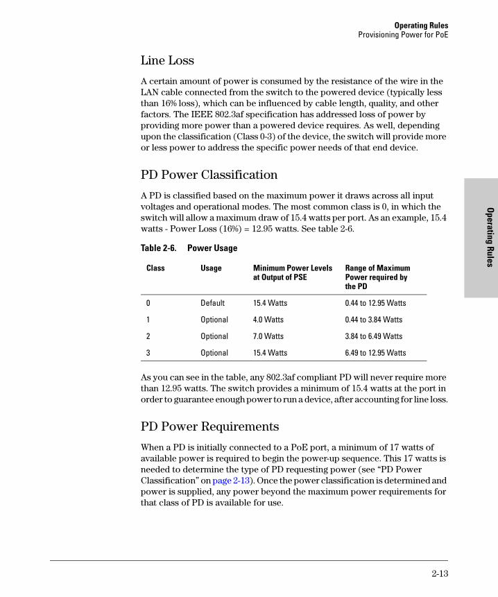
PD Power Classification
A PD is classified based on the maximum power it draws across all input voltages and operational modes. The most common class is 0, in which the switch will allow a maximum draw of 15.4 watts per port. As an example, 15.4 watts - Power Loss (16%) = 12.95 watts. See table 2-6.
Table 2-6. Power Usage
As you can see in the table, any 802.3af compliant PD will never require more than 12.95 watts. The switch provides a minimum of 15.4 watts at the port in order to guarantee enough power to run a device, after accounting for line loss.
PD Power Requirements
When a PD is initially connected to a PoE port, a minimum of 17 watts of available power is required to begin the power-up sequence. This 17 watts is needed to determine the type of PD requesting power (see “PD Power Classification” on page 2-13). Once the power classification is determined and power is supplied, any power beyond the maximum power requirements for that class of PD is available for use.
Class Usage Minimum Power Levels at Output of PSE
Range of Maximum Power required by the PD
0 Default 15.4 Watts 0.44 to 12.95 Watts
1 Optional 4.0 Watts 0.44 to 3.84 Watts
2 Optional 7.0 Watts 3.84 to 6.49 Watts
3 Optional 15.4 Watts 6.49 to 12.95 Watts
2-13

Operating RulesProvisioning Power for PoE
Ope
ratin
g Ru
les
In the default switch configuration all PoE ports have a Low priority. If the switch has less than 17 W of PoE power available, the switch transfers power from lower-priority ports to higher-priority ports.
See “Switch Priority Class” on page 2-12 for information on the use of PoE port priority classifications. Within each priority class, a lower numbered port is supplied power before a higher numbered port.
Disconnecting a PD from a port causes the switch to stop providing power to that port and makes that power available to other ports configured for PoE operation.
2-14
Planning and Im
plementation for the
Switch 2600-PW
R Series
3Planning and Implementation for the Switch 2600-PWR Series
This chapter discusses the planning process a user should follow to successfully implement PoE using a Switch 2600-PWR Series. After understanding what PoE is and its operating rules, the next step to implementation is planning. See “Specific Considerations for the 3500yl Switches” page A-2, for an example list of considerations during the planning phase.
Planning the PoE ConfigurationThis section assists you in building a PoE configuration. Using the following examples you can plan, build, and connect PoE devices quickly and easily.
There are three configurations:
■ ProCurve Switch 2600-8-PWR with Gigabit Uplink
■ ProCurve Switch 2626-PWR
■ ProCurve Switch 2650-PWR
Each example shows a complete configuration including an optional 600 RPS/EPS or 610 EPS unit. A table shows the PoE power available to connected PoE devices when using just the switch or when using the switch and either the 600 RPS/EPS or 610 EPS unit. The tables show the available power when the 600 RPS/EPS or 610 EPS unit is providing PoE power to connected switch devices.
Once you have selected your specific configuration and the PoE power provided, you then add up the maximum amount of power each of your IEEE 802.3af-compliant devices require (use maximum power in watts, usually found on a product’s data sheet). Adjust this total maximum power figure by adding 16% to account for possible line loss. This value must be less than the maximum power available shown in the table for your configuration.
3-1
Planning and Implementation for the Switch 2600-PWR SeriesPlanning the PoE Configuration
Plan
ning
and
Im
plem
enta
tion
for t
he
Switc
h 26
00-P
WR
Seri
es
If you are planning to include redundant power in your configuration you need to determine which PoE devices must receive redundant PoE power, then total their power requirements as explained in the paragraph above. The maximum power figure must be less than the maximum power available when the switch is powered by the 600 RPS/EPS or the 610 EPS unit, taking into consideration the number of switches the 600 RPS/EPS or 610 EPS unit is powering.
N o t e Full redundancy is achieved by connecting both the RPS and EPS ports of the 2600-PWR Switches to the corresponding ports of a 600 RPS/EPS.
The following examples only show the EPS connections, however, remember these switches use a single internal power supply which provides two isolated output voltages for switch and PoE functionality. One supply voltage provides power for the switch functionality while the isolated voltage provides power for the PoE functionality. If either voltage fails, the entire power supply shuts down disconnecting all switch and PoE connections. Therefore it is important to provide redundancy for each isolated voltage.
3-2
Planning and Implementation for the Switch 2600-PWR SeriesPlanning the PoE Configuration
Planning and Im
plementation for the
Switch 2600-PW
R Series
ProCurve 2600-8-PWR Configurations
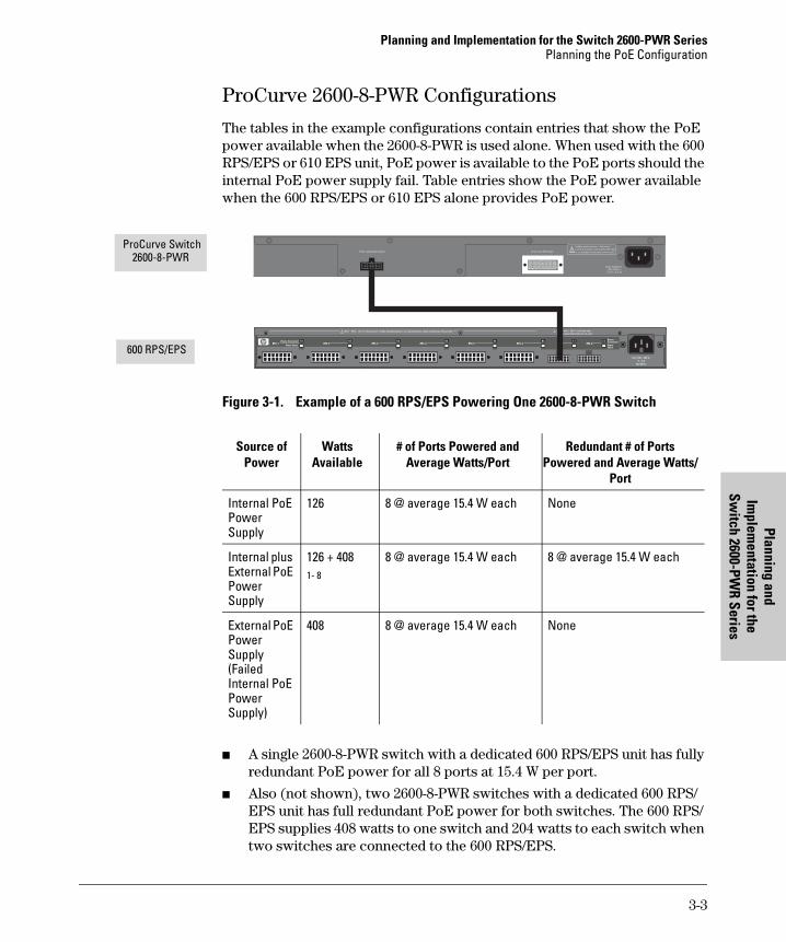
The tables in the example configurations contain entries that show the PoE power available when the 2600-8-PWR is used alone. When used with the 600 RPS/EPS or 610 EPS unit, PoE power is available to the PoE ports should the internal PoE power supply fail. Table entries show the PoE power available when the 600 RPS/EPS or 610 EPS alone provides PoE power.
Figure 3-1. Example of a 600 RPS/EPS Powering One 2600-8-PWR Switch
■ A single 2600-8-PWR switch with a dedicated 600 RPS/EPS unit has fully redundant PoE power for all 8 ports at 15.4 W per port.
■ Also (not shown), two 2600-8-PWR switches with a dedicated 600 RPS/EPS unit has full redundant PoE power for both switches. The 600 RPS/EPS supplies 408 watts to one switch and 204 watts to each switch when two switches are connected to the 600 RPS/EPS.
ProCurve RPS InputEPS R edundant Input
Line: 50/60 Hz100 240 V~3.3 A (3,3 A)
!Multiple power sources. Disconnect
both the AC power cord and the RPS cable
to completely remove power from the unit.
ProCurve Switch 2600-8-PWR
600 RPS/EPS
Source of Power
Watts Available
# of Ports Powered and Average Watts/Port
Redundant # of Ports Powered and Average Watts/
Port
Internal PoE Power Supply
126 8 @ average 15.4 W each None
Internal plus External PoE Power Supply
126 + 4081- 8
8 @ average 15.4 W each 8 @ average 15.4 W each
External PoE Power Supply (Failed Internal PoE Power Supply)
408 8 @ average 15.4 W each None
3-3
Planning and Implementation for the Switch 2600-PWR SeriesPlanning the PoE Configuration
Plan
ning
and
Im
plem
enta
tion
for t
he
Switc
h 26
00-P
WR
Seri
es
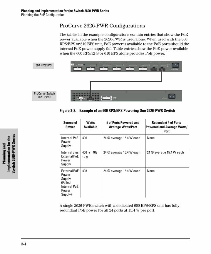
ProCurve 2626-PWR Configurations
The tables in the example configurations contain entries that show the PoE power available when the 2626-PWR is used alone. When used with the 600 RPS/EPS or 610 EPS unit, PoE power is available to the PoE ports should the internal PoE power supply fail. Table entries show the PoE power available when the 600 RPS/EPS or 610 EPS alone provides PoE power.
Figure 3-2. Example of an 600 RPS/EPS Powering One 2626-PWR Switch
A single 2626-PWR switch with a dedicated 600 RPS/EPS unit has fully redundant PoE power for all 24 ports at 15.4 W per port.
600 RPS/EPS
ProCurve Switch 2626-PWR
Source of Power
Watts Available
# of Ports Powered and Average Watts/Port
Redundant # of Ports Powered and Average Watts/
Port
Internal PoE Power Supply
406 24 @ average 15.4 W each None
Internal plus External PoE Power Supply
406 + 4081 - 24
24 @ average 15.4 W each 24 @ average 15.4 W each
External PoE Power Supply (Failed Internal PoE Power Supply)
408 24 @ average 15.4 W each None
3-4
Planning and Implementation for the Switch 2600-PWR SeriesPlanning the PoE Configuration
Planning and Im
plementation for the
Switch 2600-PW
R Series
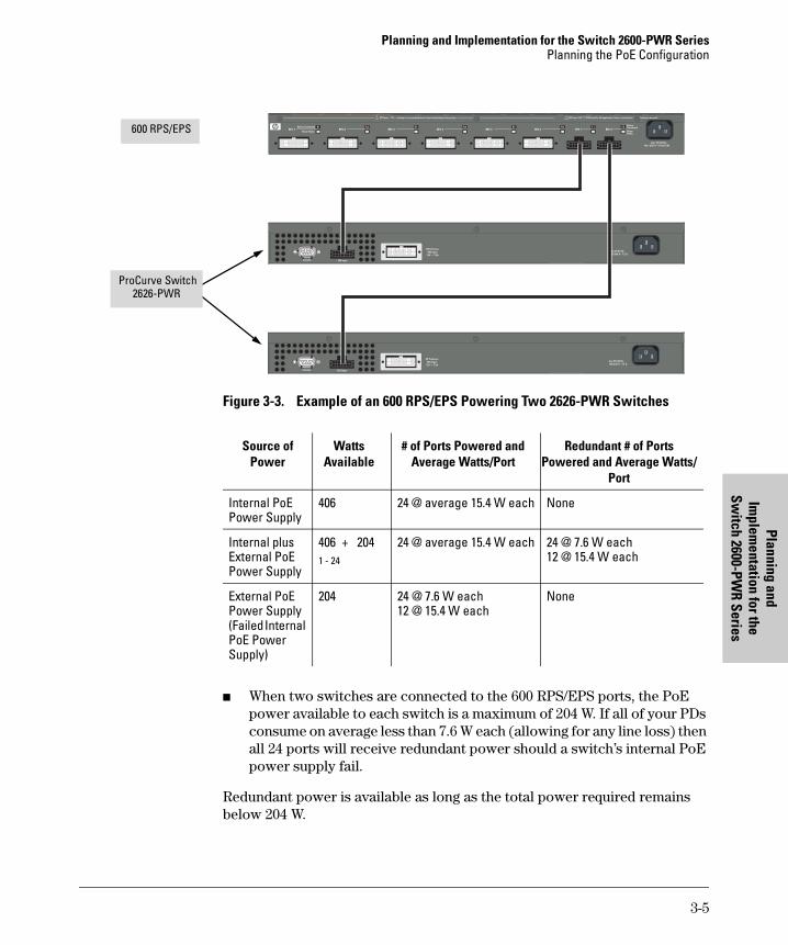
Figure 3-3. Example of an 600 RPS/EPS Powering Two 2626-PWR Switches
■ When two switches are connected to the 600 RPS/EPS ports, the PoE power available to each switch is a maximum of 204 W. If all of your PDs consume on average less than 7.6 W each (allowing for any line loss) then all 24 ports will receive redundant power should a switch’s internal PoE power supply fail.
Redundant power is available as long as the total power required remains below 204 W.
600 RPS/EPS
ProCurve Switch 2626-PWR
Source of Power
Watts Available
# of Ports Powered and Average Watts/Port
Redundant # of Ports Powered and Average Watts/
Port
Internal PoE Power Supply
406 24 @ average 15.4 W each None
Internal plus External PoE Power Supply
406 + 2041 - 24
24 @ average 15.4 W each 24 @ 7.6 W each12 @ 15.4 W each
External PoE Power Supply (Failed Internal PoE Power Supply)
204 24 @ 7.6 W each12 @ 15.4 W each
None
3-5
Planning and Implementation for the Switch 2600-PWR SeriesPlanning the PoE Configuration
Plan
ning
and
Im
plem
enta
tion
for t
he
Switc
h 26
00-P
WR
Seri
es
ProCurve 2650-PWR Configurations
The tables in the example configurations contain entries that show the PoE power available when the 2650-PWR is used alone. When used with the 600 RPS/EPS or 610 EPS unit, additional PoE power is available to the PoE ports and PoE power is available should the switch’s internal PoE power supply fail. Table entries show the PoE power available when the 600 RPS/EPS or the 610 EPS alone provides PoE power.
In the following examples using the ProCurve 2650-PWR switch, reference is made to two blocks of ports: ports 1-24 and ports 25-48. This applies when external PoE power is available from an 600 RPS/EPS or 610 EPS unit. In that case, the internal switch PoE power supply provides 406 watts of power to ports 1-24 and the 600 RPS/EPS or 610 EPS provides 408 watts of power to ports 25-48.
If you are using the ProCurve Switch 2650-PWR with external PoE power, the number of ports with available PoE power when the switch is powered by just the 600 RPS/EPS or 610 EPS unit may be less than the number of ports powered when both the switch and the 600 RPS/EPS or 610 EPS unit are supplying power. In the default configuration the number and location of ports with redundant PoE power is determined by three factors:
■ The number of switches drawing external PoE power from the 600 RPS/EPS or 610 EPS unit. If only a single switch is using external PoE power the 600 RPS/EPS or 610 EPS provides 408 watts of PoE power. If two switches are using external PoE power from the 600 RPS/EPS or two switches are connected to the same pair on the 610 EPS, a switch receives 204 watts of PoE power. Should the switch’s internal PoE power supply fail, the 600 RPS/EPS or 610 EPS provides power up to the wattage stated above.
■ When the internal PoE power supply fails, the 600 RPS/EPS reserves a minimum of 38 watts for the less-loaded bank of ports. In the default configuration, at a minimum, the first two ports in the bank (1 and 2 or 25 and 26) will have PoE power.
N o t e It is the ports configured with the highest priority of either bank (1-24 or 25-48) that will receive PoE power. For example, if the highest priority ports have been re-configured to be 23, 24 and 47, 48, then they will have PoE power.
■ In the default configuration PoE power priority is determined by port number, with the lowest numbered port having the highest priority.
If redundant PoE power is required, use the example tables to determine how much power is available to which ports.
3-6
Planning and Implementation for the Switch 2600-PWR SeriesPlanning the PoE Configuration
Planning and Im
plementation for the
Switch 2600-PW
R Series
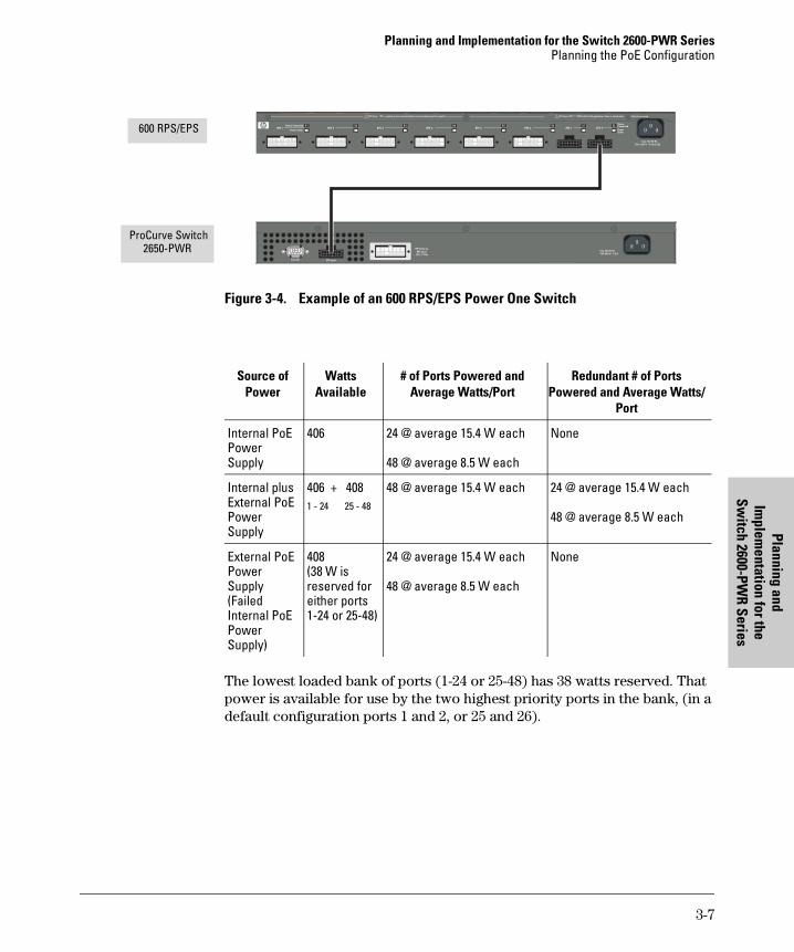
Figure 3-4. Example of an 600 RPS/EPS Power One Switch
The lowest loaded bank of ports (1-24 or 25-48) has 38 watts reserved. That power is available for use by the two highest priority ports in the bank, (in a default configuration ports 1 and 2, or 25 and 26).
600 RPS/EPS
ProCurve Switch 2650-PWR
Source of Power
Watts Available
# of Ports Powered and Average Watts/Port
Redundant # of Ports Powered and Average Watts/
Port
Internal PoE Power Supply
406 24 @ average 15.4 W each
48 @ average 8.5 W each
None
Internal plus External PoE Power Supply
406 + 4081 - 24 25 - 48
48 @ average 15.4 W each 24 @ average 15.4 W each
48 @ average 8.5 W each
External PoE Power Supply (Failed Internal PoE Power Supply)
408(38 W is reserved for either ports 1-24 or 25-48)
24 @ average 15.4 W each
48 @ average 8.5 W each
None
3-7
Planning and Implementation for the Switch 2600-PWR SeriesPlanning the PoE Configuration
Plan
ning
and
Im
plem
enta
tion
for t
he
Switc
h 26
00-P
WR
Seri
es
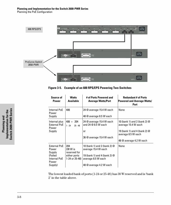
Figure 3-5. Example of an 600 RPS/EPS Powering Two Switches
The lowest loaded bank of ports (1-24 or 25-48) has 38 W reserved and is ‘bank 2’ in the table above.
600 RPS/EPS
ProCurve Switch 2650-PWR
Source of Power
Watts Available
# of Ports Powered and Average Watts/Port
Redundant # of Ports Powered and Average Watts/
Port
Internal PoE Power Supply
406 24 @ average 15.4 W each
48 @ average 8.5 W each
None
Internal plus External PoE Power Supply
406 + 2041 - 24 25 - 48
24 @ average 15.4 W eachand 24 @ 8.5 W each
or
36 @ average 15.4 W each
10 (bank 1) and 2 (bank 2) @ average 15.4 W each
19 (bank 1) and 4 (bank 2) @ average 8.5 W each
48 @ average 4.2 W each
External PoE Power Supply (Failed Internal PoE Power Supply)
204(38 W is reserved for either ports 1-24 or 25-48)
10 (bank 1) and 2 (bank 2) @ average 15.4 W each
19 (bank 1) and 4 (bank 2) @ average 8.5 W each
48 @ average 4.2 W each
None
3-8
Planning and Implementation for the Switch 2600-PWR SeriesPlanning the PoE Configuration
Planning and Im
plementation for the
Switch 2600-PW
R Series
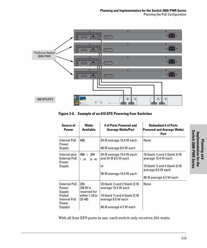
Figure 3-6. Example of an 610 EPS Powering Four Switches
With all four EPS ports in use, each switch only receives 204 watts.
Power
Fault
hp procurve
610 eps
J8169A
Fan/Temp Status flash = Temperature too highFan/Temp Status + Fault flash = Fan failure
Fan/Temp Status
Internal Power Status
In Ready Out Ready
Backup Power Ports Status
EPS Ports Pair A (408 W total for PoE applications)
EPS Ports: 50V 8.3A max each.
EPS A1PowerStatus
A2 B1 B2A1 DeviceConnected
EPS A2 EPS B1PowerStatus
DeviceConnected
EPS B2
EPS Ports Pair B (408 W total for PoE applications)
100-240 V~ 7.5 A
Line: 50/60 Hz.
50 V 16 A
RPS
12 V 7.5 A
100-240 V~ 7.5 A
Line: 50/60 Hz.
50 V 16 A
RPS
12 V 7.5 A
100-240 V~ 7.5 A
Line: 50/60 Hz.
50 V 16 A
RPS
12 V 7.5 A
100-240 V~ 7.5 A
Line: 50/60 Hz.
50 V 16 A
RPS
12 V 7.5 A
600 RPS/EPS
ProCurve Switch 2650-PWR
Source of Power
Watts Available
# of Ports Powered and Average Watts/Port
Redundant # of Ports Powered and Average Watts/
Port
Internal PoE Power Supply
406 24 @ average 15.4 W each
48 @ average 8.5 W each
None
Internal plus External PoE Power Supply
406 + 2041 - 24 25 - 48
24 @ average 15.4 W eachand 24 @ 8.5 W each
or
36 @ average 15.4 W each
10 (bank 1) and 2 (bank 2) @ average 15.4 W each
19 (bank 1) and 4 (bank 2) @ average 8.5 W each
48 @ average 4.2 W each
External PoE Power Supply (Failed Internal PoE Power Supply)
204(38 W is reserved for either 1-24 or 25-48)
10 (bank 1) and 2 (bank 2) @ average 15.4 W each
19 (bank 1) and 4 (bank 2) @ average 8.5 W each
48 @ average 4.2 W each
None
3-9

Planning and Im
plementation for the
Switch 2610-PW
R Series
4Planning and Implementation for the Switch 2610-PWR Series
This chapter discusses the planning process a user should follow to successfully implement a PoE Series 2610-PWR Switch. The 2610-PWR switches and the 2600-PWR switches common PoE implementation. Port counts, power supply wattages, specifications, and functionality for these two platforms are the same with respect to PoE.
After understanding what PoE is and its operating rules, the next step to implementation is planning. See Appendix A for an example list of considerations during the planning phase.
Planning Your PoE ConfigurationThis section assists you in building a reliable and, if required, redundant PoE configuration. Using the following examples you can plan, build, and connect your PoE devices quickly and easily.
Your configuration may vary however this section discusses some of the more common configurations.
There are three configurations:
■ ProCurve Switch 2610-24/12PWR
■ ProCurve Switch 2610-24-PWR
■ ProCurve Switch 2610-48-PWR
Each example shows a complete configuration including an optional 600 RPS/EPS or 610 EPS unit. A table shows the PoE power available to connected PoE devices when using just the switch or when using the switch and either the 600 RPS/EPS or 610 EPS unit. The tables show the available power when the 600 RPS/EPS or 610 EPS unit is providing PoE power to connected switch devices.
4-1
Planning and Implementation for the Switch 2610-PWR SeriesPlanning Your PoE Configuration
Plan
ning
and
Im
plem
enta
tion
for t
he
Switc
h 26
10-P
WR
Serie
s
Once you have selected your specific configuration and the PoE power provided, you then add up the maximum amount of power each of your IEEE 802.3af-compliant devices require (use maximum power in watts, usually found on a product’s data sheet). Adjust this total maximum power figure by adding 16% to account for possible line loss. This value must be less than the maximum power available shown in the table for your configuration.
If you are planning to include redundant power in your configuration you need to determine which PoE devices must receive redundant PoE power, then total their power requirements as explained in the paragraph above. The maximum power figure must be less than the maximum power available when the switch is powered by the 600 RPS/EPS or the 610 EPS unit, taking into consideration the number of switches the 600 RPS/EPS or 610 EPS unit is powering.
N o t e Full redundancy is achieved by connecting both the RPS and EPS ports of the 2610-PWR switches to the corresponding ports of a 600 RPS/EPS.
The following examples only show the EPS connections, however, remember these switches use a single internal power supply which provides two isolated output voltages for switch and PoE functionality. One supply voltage provides power for the switch functionality while the isolated voltage provides power for the PoE functionality. If either voltage fails, the entire power supply shuts down disconnecting all switch and PoE connections. Therefore it is important to provide redundancy for each isolated voltage.
4-2
Planning and Implementation for the Switch 2610-PWR SeriesPlanning Your PoE Configuration
Planning and Im
plementation for the
Switch 2610-PW
R Series
ProCurve 2610-24/12PWR ConfigurationsThe tables in the example configurations contain entries that show the PoE power available when the 2610-24/12PWR is used alone. When used with the 600 RPS/EPS or 610 EPS unit, PoE power is available to the PoE ports should the internal PoE power supply fail. Table entries show the PoE power available when the 600 RPS/EPS or 610 EPS alone provides PoE power.
Figure 4-1. Example of a 600 RPS/EPS Powering One 2610-24/12PWR Switch
■ A single 2610-24/12PWR switch with a dedicated 600 RPS/EPS unit has fully redundant PoE power for the 12 PoE ports at 7.5 W per port or 12 ports at 15.4 W per port. Only 12 ports can be PoE powered.
■ The internal power supply can provide up to 126 W of power to be used on all 12 PoE ports. The power can be allocated up to the maximum of 12 ports, or 126 W, whichever is depleted first with a reserve of 22 W maintained by the switch for power management. If more power is needed to allow the maximum of 15.4 W on all 12 ports, an external power supply accessory is needed.
■ Also (not shown), two 2610-24/12PWR switches with a dedicated 600 RPS/EPS unit has full redundant PoE power for both switches. The 600 RPS/EPS supplies 408 watts to one switch and 204 watts to each switch when two switches are connected to the 600 RPS/EPS.
Device Connected
Power Status
R1 R2 R3 R4 R5 R6 E1DeviceConnectedPowerStatus
E2RPS 1 RPS 2 RPS 3 RPS 4 RPS 5 RPS 6 EPS 1 EPS 2
EPS Power: 50V 370W total for PoE applications. Power is shared when both ports are used.RPS Power: 12V backup to one connected device. Lowest-numbered port has priority.
Line: 50/60 Hz.100 -240 V~ 9.1A (9,1A)
Console
!
Line 50/60 Hz.100-240 V~ 7.5 A
EPS Input
HP ProCurveRPS Input
12V 7.5A
ProCurve Switch 2610-24/12PWR
600 RPS/EPS
Source of Power Watts Available
# of Ports Powered and Average Watts/Port
Redundant # of Ports Powered and Average Watts/
Port
Internal PoE Power Supply
126 12 @ average 7.5 W each8 @ average 15.4 W each
None
Internal plus External PoE Power Supply
126 + 4081 - 12
12 @ average 15.4 W each 12 @ average 7.5 W each12 @ average 15.4 W each
External PoE Power Supply (Failed Internal PoE Power Supply)
408 12 @ average 7.5 W each12 @ average 15.4 W each
None
4-3
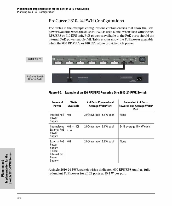
Planning and Implementation for the Switch 2610-PWR SeriesPlanning Your PoE Configuration
Plan
ning
and
Im
plem
enta
tion
for t
he
Switc
h 26
10-P
WR
Serie
s
ProCurve 2610-24-PWR Configurations
The tables in the example configurations contain entries that show the PoE power available when the 2610-24-PWR is used alone. When used with the 600 RPS/EPS or 610 EPS unit, PoE power is available to the PoE ports should the internal PoE power supply fail. Table entries show the PoE power available when the 600 RPS/EPS or 610 EPS alone provides PoE power.
Figure 4-2. Example of an 600 RPS/EPS Powering One 2610-24-PWR Switch
A single 2610-24-PWR switch with a dedicated 600 RPS/EPS unit has fully redundant PoE power for all 24 ports at 15.4 W per port.
Device Connected
Power Status
R1 R2 R3 R4 R5 R6 E1DeviceConnectedPowerStatus
E2RPS 1 RPS 2 RPS 3 RPS 4 RPS 5 RPS 6 EPS 1 EPS 2
EPS Power: 50V 370W total for PoE applications. Power is shared when both ports are used.RPS Power: 12V backup to one connected device. Lowest-numbered port has priority.
Line: 50/60 Hz.100 -240 V~ 9.1A (9,1A)
Console
!
Line 50/60 Hz.100-240 V~ 7.5 A
EPS Input
HP ProCurveRPS Input
12V 7.5A
ProCurve Switch 2610-24-PWR
600 RPS/EPS
Source of Power
Watts Available
# of Ports Powered and Average Watts/Port
Redundant # of Ports Powered and Average Watts/
Port
Internal PoE Power Supply
406 24 @ average 15.4 W each None
Internal plus External PoE Power Supply
406 + 4081 - 24
24 @ average 15.4 W each 24 @ average 15.4 W each
External PoE Power Supply (Failed Internal PoE Power Supply)
408 24 @ average 15.4 W each None
4-4
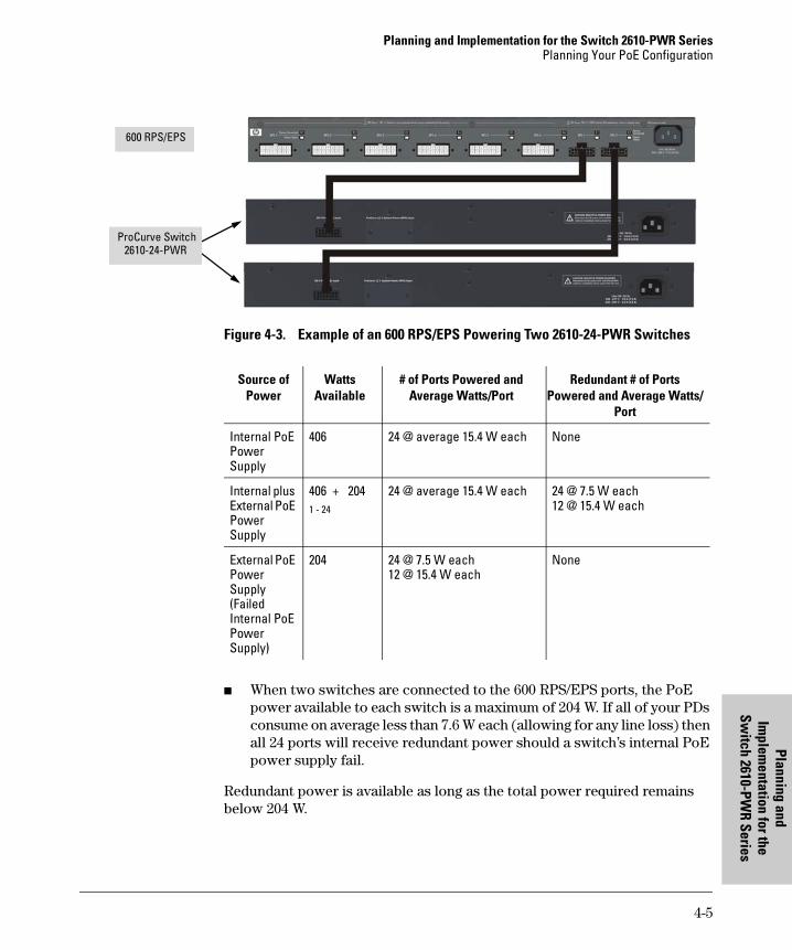
Planning and Implementation for the Switch 2610-PWR SeriesPlanning Your PoE Configuration
Planning and Im
plementation for the
Switch 2610-PW
R Series
Figure 4-3. Example of an 600 RPS/EPS Powering Two 2610-24-PWR Switches
■ When two switches are connected to the 600 RPS/EPS ports, the PoE power available to each switch is a maximum of 204 W. If all of your PDs consume on average less than 7.6 W each (allowing for any line loss) then all 24 ports will receive redundant power should a switch’s internal PoE power supply fail.
Redundant power is available as long as the total power required remains below 204 W.
600 RPS/EPS
ProCurve Switch 2610-24-PWR
Source of Power
Watts Available
# of Ports Powered and Average Watts/Port
Redundant # of Ports Powered and Average Watts/
Port
Internal PoE Power Supply
406 24 @ average 15.4 W each None
Internal plus External PoE Power Supply
406 + 2041 - 24
24 @ average 15.4 W each 24 @ 7.5 W each12 @ 15.4 W each
External PoE Power Supply (Failed Internal PoE Power Supply)
204 24 @ 7.5 W each12 @ 15.4 W each
None
4-5
Planning and Implementation for the Switch 2610-PWR SeriesPlanning Your PoE Configuration
Plan
ning
and
Im
plem
enta
tion
for t
he
Switc
h 26
10-P
WR
Serie
s
ProCurve 2610-48-PWR Configurations
The tables in the example configurations contain entries that show the PoE power available when the 2610-48-PWR is used alone. When used with the 600 RPS/EPS or 610 EPS unit, additional PoE power is available to the PoE ports and PoE power is available should the switch’s internal PoE power supply fail. Table entries show the PoE power available when the 600 RPS/EPS or the 610 EPS alone provides PoE power.
In the following examples using the ProCurve 2610-48-PWR switch, reference is made to two blocks of ports: ports 1-24 and ports 25-48. This applies when external PoE power is available from an 600 RPS/EPS or 610 EPS unit. In that case, the internal switch PoE power supply provides 406 watts of power to ports 1-24 and the 600 RPS/EPS or 610 EPS provides 408 watts of power to ports 25-48.
If you are using the ProCurve Switch 2610-48-PWR with external PoE power, the number of ports with available PoE power when the switch is powered by just the 600 RPS/EPS or 610 EPS unit may be less than the number of ports powered when both the switch and the 600 RPS/EPS or 610 EPS unit are supplying power. In the default configuration the number and location of ports with redundant PoE power is determined by three factors:
■ The number of switches drawing external PoE power from the 600 RPS/EPS or 610 EPS unit. If only a single switch is using external PoE power the 600 RPS/EPS or 610 EPS provides 408 watts of PoE power. If two switches are using external PoE power from the 600 RPS/EPS or two switches are connected to the same pair on the 610 EPS, a switch receives 204 watts of PoE power. Should the switch’s internal PoE power supply fail, the 600 RPS/EPS or 610 EPS provides power up to the wattage stated above.
■ When the internal PoE power supply fails, the 600 RPS/EPS reserves a minimum of 22 watts for the less-loaded bank of ports. In the default configuration, at a minimum, the first two ports in the bank (1 and 2 or 25 and 26) will have PoE power.
N o t e It is the ports configured with the highest priority of either bank (1-24 or 25-48) that will receive PoE power. For example, if the highest priority ports have been re-configured to be 23, 24 and 47, 48, then they will have PoE power.
■ In the default configuration PoE power priority is determined by port number, with the lowest numbered port having the highest priority.
If redundant PoE power is required, use the example tables to determine how much power is available to which ports.
4-6
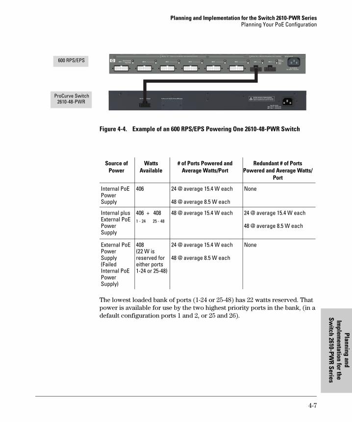
Planning and Implementation for the Switch 2610-PWR SeriesPlanning Your PoE Configuration
PlanninIm
plementat
Switch 2610-P
Figure 4-4. Example of an 600 RPS/EPS Powering One 2610-48-PWR Switch
The lowest loaded bank of ports (1-24 or 25-48) has 22 watts reserved. That power is available for use by the two highest priority ports in the bank, (in a default configuration ports 1 and 2, or 25 and 26).
Device Connected
Power Status
R1 R2 R3 R4 R5 R6 E1DeviceConnectedPowerStatus
E2RPS 1 RPS 2 RPS 3 RPS 4 RPS 5 RPS 6 EPS 1 EPS 2
EPS Power: 50V 370W total for PoE applications. Power is shared when both ports are used.RPS Power: 12V backup to one connected device. Lowest-numbered port has priority.
Line: 50/60 Hz.100 -240 V~ 9.1A (9,1A)
Console
!
Line 50/60 Hz.100-240 V~ 7.5 A
EPS Input
HP ProCurveRPS Input
12V 7.5A
ProCurve Switch 2610-48-PWR
600 RPS/EPS
Source of Power
Watts Available
# of Ports Powered and Average Watts/Port
Redundant # of Ports Powered and Average Watts/
Port
Internal PoE Power Supply
406 24 @ average 15.4 W each
48 @ average 8.5 W each
None
Internal plus External PoE Power Supply
406 + 4081 - 24 25 - 48
48 @ average 15.4 W each 24 @ average 15.4 W each
48 @ average 8.5 W each
External PoE Power Supply (Failed Internal PoE Power Supply)
408(22 W is reserved for either ports 1-24 or 25-48)
24 @ average 15.4 W each
48 @ average 8.5 W each
None
4-7
g and ion for the W
R Series
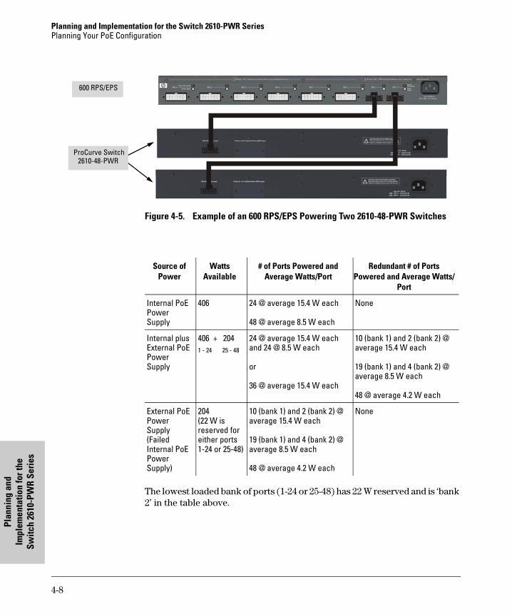
Planning and Implementation for the Switch 2610-PWR SeriesPlanning Your PoE Configuration
Plan
ning
and
Im
plem
enta
tion
for t
he
Switc
h 26
10-P
WR
Serie
s
Figure 4-5. Example of an 600 RPS/EPS Powering Two 2610-48-PWR Switches
The lowest loaded bank of ports (1-24 or 25-48) has 22 W reserved and is ‘bank 2’ in the table above.
600 RPS/EPS
ProCurve Switch 2610-48-PWR
Source of Power
Watts Available
# of Ports Powered and Average Watts/Port
Redundant # of Ports Powered and Average Watts/
Port
Internal PoE Power Supply
406 24 @ average 15.4 W each
48 @ average 8.5 W each
None
Internal plus External PoE Power Supply
406 + 2041 - 24 25 - 48
24 @ average 15.4 W eachand 24 @ 8.5 W each
or
36 @ average 15.4 W each
10 (bank 1) and 2 (bank 2) @ average 15.4 W each
19 (bank 1) and 4 (bank 2) @ average 8.5 W each
48 @ average 4.2 W each
External PoE Power Supply (Failed Internal PoE Power Supply)
204(22 W is reserved for either ports 1-24 or 25-48)
10 (bank 1) and 2 (bank 2) @ average 15.4 W each
19 (bank 1) and 4 (bank 2) @ average 8.5 W each
48 @ average 4.2 W each
None
4-8
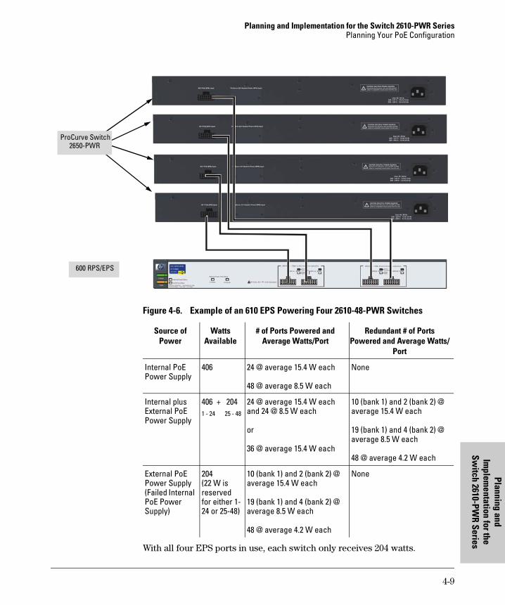
Planning and Implementation for the Switch 2610-PWR SeriesPlanning Your PoE Configuration
Planning and Im
plementation for the
Switch 2610-PW
R Series
Figure 4-6. Example of an 610 EPS Powering Four 2610-48-PWR Switches
With all four EPS ports in use, each switch only receives 204 watts.
600 RPS/EPS
ProCurve Switch 2650-PWR
Source of Power
Watts Available
# of Ports Powered and Average Watts/Port
Redundant # of Ports Powered and Average Watts/
Port
Internal PoE Power Supply
406 24 @ average 15.4 W each
48 @ average 8.5 W each
None
Internal plus External PoE Power Supply
406 + 2041 - 24 25 - 48
24 @ average 15.4 W eachand 24 @ 8.5 W each
or
36 @ average 15.4 W each
10 (bank 1) and 2 (bank 2) @ average 15.4 W each
19 (bank 1) and 4 (bank 2) @ average 8.5 W each
48 @ average 4.2 W each
External PoE Power Supply (Failed Internal PoE Power Supply)
204(22 W is reserved for either 1-24 or 25-48)
10 (bank 1) and 2 (bank 2) @ average 15.4 W each
19 (bank 1) and 4 (bank 2) @ average 8.5 W each
48 @ average 4.2 W each
None
4-9

Planning and Im
plementation for the
5
Planning and Implementation for the Switch xl PoE module
This chapter discusses the planning process a user should follow to successfully implement PoE using a Series 5300xl PoE module. After understanding what PoE is and its operating rules, the next step to implementation is planning. See Appendix A for an example list of considerations during the planning phase.
Planning Your PoE Configuration
This section assists you in building a reliable PoE configuration. Using the following examples you can plan, build, and connect your PoE devices quickly and easily.
Your configuration may vary however this section discusses some of the more common configurations.
There are five configurations:
■ One module with a 600 RPS/EPS
■ Two modules with a 600 RPS/EPS
■ Two modules with a 610 EPS using a separate pair of power ports
■ Two modules with a 610 EPS using the same pair of power ports
■ Four modules with a 610 EPS
Each example shows a complete configuration using either a 600 RPS/EPS or 610 EPS unit. A table shows the PoE power available to connected PoE devices
Once you have selected your specific configuration and the PoE power provided, you then add up the maximum amount of power each of your IEEE 802.3af-compliant devices require (use maximum power in watts, usually found on a product’s data sheet). Adjust this total maximum power figure by adding 16% to account for possible line loss. This value must be less than the maximum power available shown in the table for your configuration.
5-1
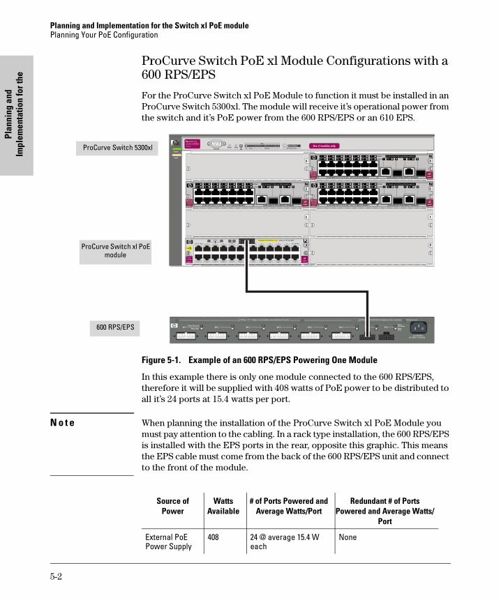
Planning and Implementation for the Switch xl PoE modulePlanning Your PoE Configuration
Plan
ning
and
Im
plem
enta
tion
for t
he
ProCurve Switch PoE xl Module Configurations with a 600 RPS/EPS
For the ProCurve Switch xl PoE Module to function it must be installed in an ProCurve Switch 5300xl. The module will receive it’s operational power from the switch and it’s PoE power from the 600 RPS/EPS or an 610 EPS.
Figure 5-1. Example of an 600 RPS/EPS Powering One Module
In this example there is only one module connected to the 600 RPS/EPS, therefore it will be supplied with 408 watts of PoE power to be distributed to all it’s 24 ports at 15.4 watts per port.
N o t e When planning the installation of the ProCurve Switch xl PoE Module you must pay attention to the cabling. In a rack type installation, the 600 RPS/EPS is installed with the EPS ports in the rear, opposite this graphic. This means the EPS cable must come from the back of the 600 RPS/EPS unit and connect to the front of the module.
/+���������
�� ������
������
0�1����
��
���� ���� � � ! "
��&'�����%(�%%&�)���� �&� �*���+������,�-��&��.)
�� �
�%�������%�$#
�!
��
�"
�� �� �
�# �$
��� �� �� ���������
������
�������
600 RPS/EPS
ProCurve Switch 5300xl
ProCurve Switch xl PoE module
Source of Power
Watts Available
# of Ports Powered and Average Watts/Port
Redundant # of Ports Powered and Average Watts/
Port
External PoE Power Supply
408 24 @ average 15.4 W each
None
5-2
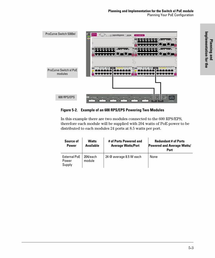
Planning and Implementation for the Switch xl PoE modulePlanning Your PoE Configuration
Planning and Im
plementation for the
Figure 5-2. Example of an 600 RPS/EPS Powering Two Modules
In this example there are two modules connected to the 600 RPS/EPS, therefore each module will be supplied with 204 watts of PoE power to be distributed to each modules 24 ports at 8.5 watts per port.
/+���������
�� ������
������
0�1����
��
���� ���� � � ! "
��&'�����%(�%%&�)���� �&� �*���+������,�-��&��.)
�� �
�%�������%�$#
�!
��
�"
�� �� �
�# �$
��� �� �� ���������
������
�������
/+���������
�� ������
������
0�1����
��
���� ���� � � ! "
��&'�����%(�%%&�)���� �&� �*���+������,�-��&��.)
�� �
�%�������%�$#
�!
��
�"
�� �� �
�# �$
��� �� �� ���������
������
�������
600 RPS/EPS
ProCurve Switch 5300xl
ProCurve Switch xl PoE modules
Source of Power
Watts Available
# of Ports Powered and Average Watts/Port
Redundant # of Ports Powered and Average Watts/
Port
External PoE Power Supply
204/each module
24 @ average 8.5 W each None
5-3
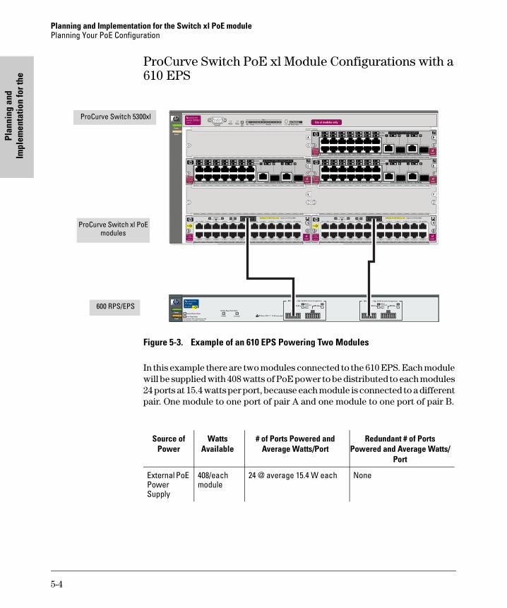
Planning and Implementation for the Switch xl PoE modulePlanning Your PoE Configuration
Plan
ning
and
Im
plem
enta
tion
for t
he
ProCurve Switch PoE xl Module Configurations with a 610 EPS
Figure 5-3. Example of an 610 EPS Powering Two Modules
In this example there are two modules connected to the 610 EPS. Each module will be supplied with 408 watts of PoE power to be distributed to each modules 24 ports at 15.4 watts per port, because each module is connected to a different pair. One module to one port of pair A and one module to one port of pair B.
/+���������
�� ������
������
0�1����
��
���� ���� � � ! "
��&'�����%(�%%&�)���� �&� �*���+������,�-��&��.)
�� �
�%�������%�$#
�!
��
�"
�� �� �
�# �$
��� �� �� ���������
������
�������
/+���������
�� ������
������
0�1����
��
���� ���� � � ! "
��&'�����%(�%%&�)���� �&� �*���+������,�-��&��.)
�� �
�%�������%�$#
�!
��
�"
�� �� �
�# �$
��� �� �� ���������
������
�������
600 RPS/EPS
ProCurve Switch 5300xl
ProCurve Switch xl PoE modules
Source of Power
Watts Available
# of Ports Powered and Average Watts/Port
Redundant # of Ports Powered and Average Watts/
Port
External PoE Power Supply
408/each module
24 @ average 15.4 W each None
5-4
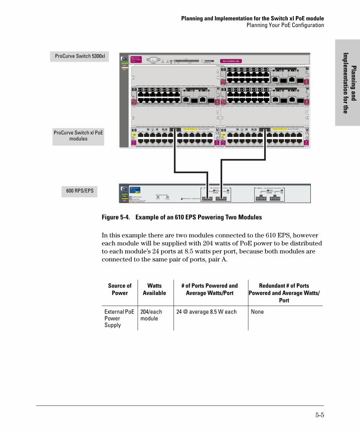
Planning and Implementation for the Switch xl PoE modulePlanning Your PoE Configuration
Planning and Im
plementation for the
Figure 5-4. Example of an 610 EPS Powering Two Modules
In this example there are two modules connected to the 610 EPS, however each module will be supplied with 204 watts of PoE power to be distributed to each module’s 24 ports at 8.5 watts per port, because both modules are connected to the same pair of ports, pair A.
/+���������
�� ������
������
0�1����
��
���� ���� � � ! "
��&'�����%(�%%&�)���� �&� �*���+������,�-��&��.)
�� �
�%�������%�$#
�!
��
�"
�� �� �
�# �$
��� �� �� ���������
������
�������
/+���������
�� ������
������
0�1����
��
���� ���� � � ! "
��&'�����%(�%%&�)���� �&� �*���+������,�-��&��.)
�� �
�%�������%�$#
�!
��
�"
�� �� �
�# �$
��� �� �� ���������
������
�������
600 RPS/EPS
ProCurve Switch 5300xl
ProCurve Switch xl PoE modules
Source of Power
Watts Available
# of Ports Powered and Average Watts/Port
Redundant # of Ports Powered and Average Watts/
Port
External PoE Power Supply
204/each module
24 @ average 8.5 W each None
5-5
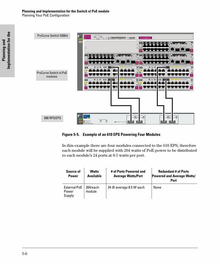
Planning and Implementation for the Switch xl PoE modulePlanning Your PoE Configuration
Plan
ning
and
Im
plem
enta
tion
for t
he
Figure 5-5. Example of an 610 EPS Powering Four Modules
In this example there are four modules connected to the 610 EPS, therefore each module will be supplied with 204 watts of PoE power to be distributed to each module’s 24 ports at 8.5 watts per port.
/+���������
�� ������
������
0�1����
��
���� ���� � � ! "
��&'�����%(�%%&�)���� �&� �*���+������,�-��&��.)
�� �
�%�������%�$#
�!
��
�"
�� �� �
�# �$
��� �� �� ���������
������
�������
/+���������
�� ������
������
0�1����
��
���� ���� � � ! "
��&'�����%(�%%&�)���� �&� �*���+������,�-��&��.)
�� �
�%�������%�$#
�!
��
�"
�� �� �
�# �$
��� �� �� ���������
������
�������
/+���������
�� ������
������
0�1����
��
���� ���� � � ! "
��&'�����%(�%%&�)���� �&� �*���+������,�-��&��.)
�� �
�%�������%�$#
�!
��
�"
�� �� �
�# �$
��� �� �� ���������
������
�������
/+���������
�� ������
������
0�1����
��
���� ���� � � ! "
��&'�����%(�%%&�)���� �&� �*���+������,�-��&��.)
�� �
�%�������%�$#
�!
��
�"
�� �� �
�# �$
��� �� �� ���������
������
�������
600 RPS/EPS
ProCurve Switch 5300xl
ProCurve Switch xl PoE modules
Source of Power
Watts Available
# of Ports Powered and Average Watts/Port
Redundant # of Ports Powered and Average Watts/
Port
External PoE Power Supply
204/each module
24 @ average 8.5 W each None
5-6
Planning and Im
plementation for the
Switch 3500yl Series
6
Planning and Implementation for the Switch 3500yl Series
This chapter discusses the planning process a user should follow to successfully implement PoE using a Series 3500yl Switch. After understanding what PoE is and its operating rules, the next step to implementation is planning. See “Specific Considerations for the 3500yl Switches” page A-2, for an example list of considerations during the planning phase.
Planning Your PoE ConfigurationThis section assists you in building a PoE configuration. Using the following examples you can plan, build, and connect PoE devices quickly and easily.
There are four configurations:
■ ProCurve Switch 3500yl-24G-PWR
■ ProCurve Switch 3500yl-24G-PWR connecting an external power supply.
■ ProCurve Switch 3500yl-48G-PWR
■ ProCurve Switch 3500yl-48G-PWR connecting an external power supply.
Each example shows a complete configuration. A table shows the PoE power available to connected PoE devices when using just the switch.
Once you have selected your specific configuration and the PoE power provided, you then add up the maximum amount of power each device requires (use maximum power in watts, usually found on a product’s data sheet). Adjust this total maximum power figure by adding 16% to account for possible line loss. This value must be less than the maximum power available shown in the table for your configuration.
6-1
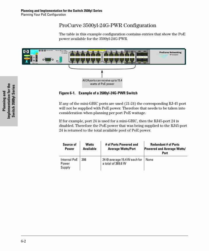
Planning and Implementation for the Switch 3500yl SeriesPlanning Your PoE Configuration
Plan
ning
and
Im
plem
enta
tion
for t
he
Switc
h 35
00yl
Ser
ies
ProCurve 3500yl-24G-PWR Configuration
The table in this example configuration contains entries that show the PoE power available for the 3500yl-24G-PWR.
Figure 6-1. Example of a 3500yl-24G-PWR Switch
If any of the mini-GBIC ports are used (21-24) the corresponding RJ-45 port will not be supplied with PoE power. Therefore that needs to be taken into consideration when planning per port PoE wattage.
If for example, port 24 is used for a mini-GBIC, then the RJ45-port 24 is disabled. Therefore the PoE power that was being supplied to the RJ45-port 24 is returned to the total available pool of PoE power.
All 24 ports can receive up to 15.4 watts of PoE power
Source of Power
Watts Available
# of Ports Powered and Average Watts/Port
Redundant # of Ports Powered and Average Watts/
Port
Internal PoE Power Supply
398 24 @ average 15.4 W each for a total of 369.6 W
None
6-2
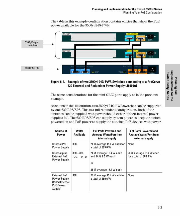
Planning and Implementation for the Switch 3500yl SeriesPlanning Your PoE Configuration
Planning and Im
plementation for the
Switch 3500yl Series
The table in this example configuration contains entries that show the PoE power available for the 3500yl-24G-PWR.
Figure 6-2. Example of two 3500yl-24G-PWR Switches connecting to a ProCurve 620 External and Redundant Power Supply (J8696A)
The same considerations for the mini-GBIC ports apply as in the previous example.
As shown in this illustration, two 3500yl-24G-PWR switches can be supported by one 620 RPS/EPS. This is a full redundant configuration. Both of the switches can be supplied with power should either of their internal power supplies fail. The 620 RPS/EPS can supply system power to keep the switch powered on and PoE power to supply the attached PoE devices with power.
3500yl 24 port switches
620 RPS/EPS
Source of Power
Watts Available
# of Ports Powered and Average Watts/Port from
internal supply
# of Ports Powered and Average Watts/Port from
external supply
Internal PoE Power Supply
398 24 @ average 15.4 W each for a total of 369.6 W
None
Internal plus External PoE Power Supply
398 + 3881 - 24 25 - 48
24 @ average 15.4 W eachand 24 @ 8.5 W each
or
36 @ average 15.4 W each
24 @ average 15.4 W each for a total of 369.6 W
External PoE Power Supply (failed Internal PoE Power Supply)
388 24 @ average 15.4 W each for a total of 369.6 W
None
6-3
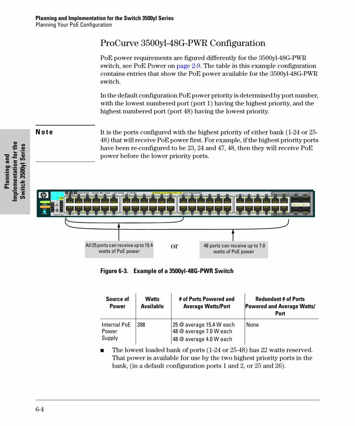
Planning and Implementation for the Switch 3500yl SeriesPlanning Your PoE Configuration
Plan
ning
and
Im
plem
enta
tion
for t
he
Switc
h 35
00yl
Ser
ies
ProCurve 3500yl-48G-PWR Configuration
PoE power requirements are figured differently for the 3500yl-48G-PWR switch, see PoE Power on page 2-9. The table in this example configuration contains entries that show the PoE power available for the 3500yl-48G-PWR switch.
In the default configuration PoE power priority is determined by port number, with the lowest numbered port (port 1) having the highest priority, and the highest numbered port (port 48) having the lowest priority.
N o t e It is the ports configured with the highest priority of either bank (1-24 or 25-48) that will receive PoE power first. For example, if the highest priority ports have been re-configured to be 23, 24 and 47, 48, then they will receive PoE power before the lower priority ports.
Figure 6-3. Example of a 3500yl-48G-PWR Switch
■ The lowest loaded bank of ports (1-24 or 25-48) has 22 watts reserved. That power is available for use by the two highest priority ports in the bank, (in a default configuration ports 1 and 2, or 25 and 26).
All 25 ports can receive up to 15.4 watts of PoE power
or 48 ports can receive up to 7.0 watts of PoE power
Source of Power
Watts Available
# of Ports Powered and Average Watts/Port
Redundant # of Ports Powered and Average Watts/
Port
Internal PoE Power Supply
398 25 @ average 15.4 W each48 @ average 7.0 W each48 @ average 4.0 W each
None
6-4

Planning and Implementation for the Switch 3500yl SeriesPlanning Your PoE Configuration
Planning and Im
plementation for the
Switch 3500yl Series
For example, the switch starts with 398 watts. Then it reserves 22 watts per bank leaving 354 watts total for allocation. If ports 1-24 are chosen to be used then the 22 watts that was held in reserve for that bank of ports will be added back in for a total of 376 watts.
It takes 369.6 watts to fully provision 24 ports (plus 5 watts to account for load fluctuations), leaving 1.4 watts to be returned to the pool of available watts. This can then be added to the 22 watts held in reserve for the bank of ports 25-48, giving a total of available watts of 23.4 watts.
Since a port requires 17 watts to power up a device, there is enough available power to power one more device in a port, somewhere between 25-48, giving a total number of powered ports of 25.
Another example would be to load balance or split the number of devices and wattage between the two banks of ports. In this example the total wattage of 398 would be divided in half, 199 watts would be allocated to ports 1-24, and 199 watts would be allocated to ports 25-48.
By load balancing in this manner there could be 12 devices on one bank of ports, say 1-24, and 13 on the other bank of ports, 25-48.
Both of these examples use maximum device wattage. If however, devices using lower wattages are connected there could be more devices connected to the switch than shown in these examples. Each environment will be different.
There is a CLI command available, the THRESHOLD command. It has an informational only result. This command sets a threshold, by percent, to inform you the switch is now using more than a certain percentage of PoE power. For example if the threshold is set at 50%, the switch will issue an information message informing you the switch has exceeded the threshold when 51% of available PoE power is being used. Also see page 7-7 for an example. For more information on the threshold command, Refer to the Management and Configuration Guide which is on the ProCurve Web site, www.procurve.com. (See page 1-8 for details.)
6-5
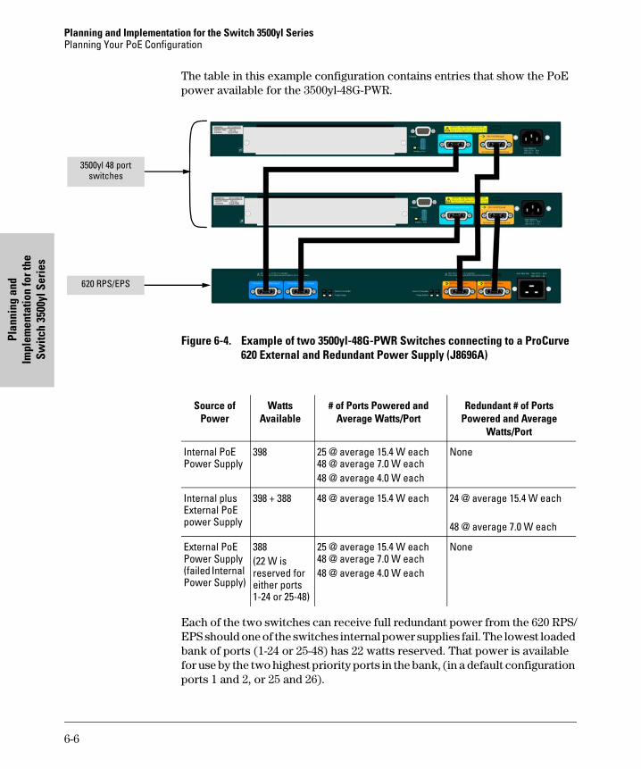
Planning and Implementation for the Switch 3500yl SeriesPlanning Your PoE Configuration
Plan
ning
and
Im
plem
enta
tion
for t
he
Switc
h 35
00yl
Ser
ies
The table in this example configuration contains entries that show the PoE power available for the 3500yl-48G-PWR.
Figure 6-4. Example of two 3500yl-48G-PWR Switches connecting to a ProCurve 620 External and Redundant Power Supply (J8696A)
Each of the two switches can receive full redundant power from the 620 RPS/EPS should one of the switches internal power supplies fail. The lowest loaded bank of ports (1-24 or 25-48) has 22 watts reserved. That power is available for use by the two highest priority ports in the bank, (in a default configuration ports 1 and 2, or 25 and 26).
3500yl 48 port switches
620 RPS/EPS
Source of Power
Watts Available
# of Ports Powered and Average Watts/Port
Redundant # of Ports Powered and Average
Watts/Port
Internal PoE Power Supply
398 25 @ average 15.4 W each48 @ average 7.0 W each48 @ average 4.0 W each
None
Internal plus External PoE power Supply
398 + 388 48 @ average 15.4 W each 24 @ average 15.4 W each
48 @ average 7.0 W each
External PoE Power Supply (failed Internal Power Supply)
388(22 W is reserved for either ports 1-24 or 25-48)
25 @ average 15.4 W each48 @ average 7.0 W each48 @ average 4.0 W each
None
6-6
Planning and Im
plementation for the
Switch 5400zl/8200zl Series
7
Planning and Implementation for the Switch 5400zl/8200zl Series
This chapter discusses the planning process a user should follow to successfully implement a PoE Series 5400zl/8200zl Switch. The 5412zl chassis and the 8212zl chassis share a completely common PoE implementation. Port counts, power supply wattages, specifications, and functionality for these two platforms are the same with respect to PoE.
After understanding what PoE is and its operating rules, the next step to implementation is planning. See Appendix A for an example list of considerations during the planning phase.
Planning Your PoE ConfigurationThis section assists you in building a reliable and, if required, redundant PoE configuration. Using the following examples you can plan, build, and connect your PoE devices quickly and easily.
Your configuration may vary however this section discusses some of the more common configurations.
7-1
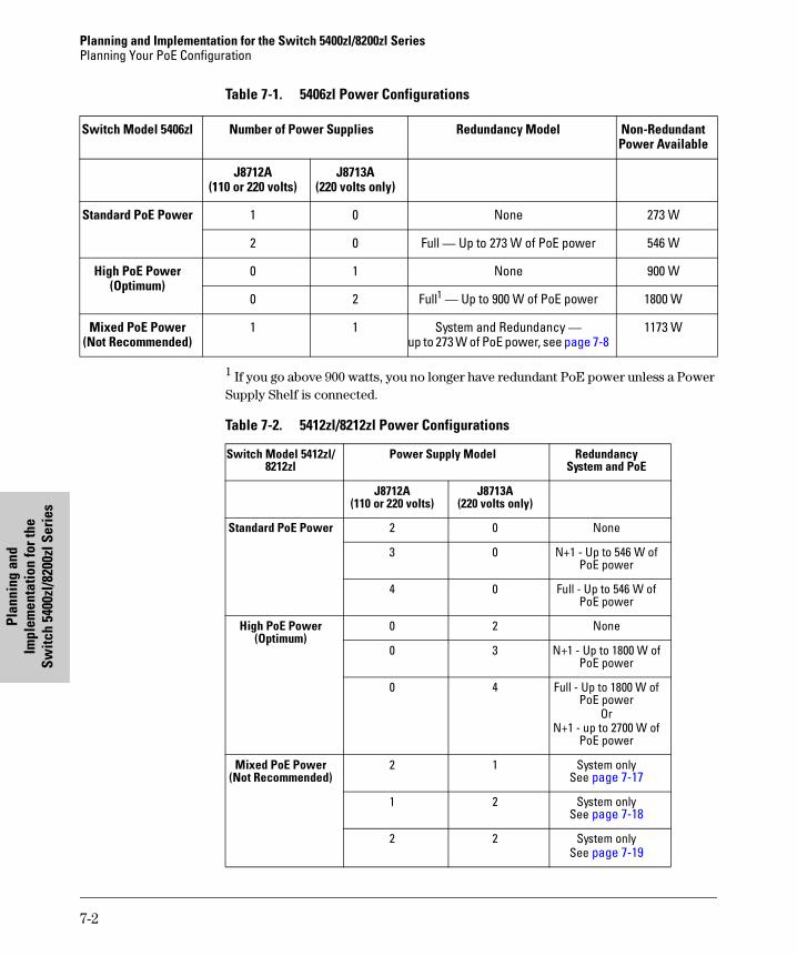
Planning and Implementation for the Switch 5400zl/8200zl SeriesPlanning Your PoE Configuration
Plan
ning
and
Im
plem
enta
tion
for t
he
Switc
h 54
00zl
/820
0zl S
erie
s
Table 7-1. 5406zl Power Configurations
1 If you go above 900 watts, you no longer have redundant PoE power unless a Power Supply Shelf is connected.
Table 7-2. 5412zl/8212zl Power Configurations
Switch Model 5406zl Number of Power Supplies Redundancy Model Non-Redundant Power Available
J8712A(110 or 220 volts)
J8713A(220 volts only)
Standard PoE Power 1 0 None 273 W
2 0 Full — Up to 273 W of PoE power 546 W
High PoE Power (Optimum)
0 1 None 900 W
0 2 Full1 — Up to 900 W of PoE power 1800 W
Mixed PoE Power (Not Recommended)
1 1 System and Redundancy — up to 273 W of PoE power, see page 7-8
1173 W
Switch Model 5412zl/8212zl
Power Supply Model RedundancySystem and PoE
J8712A(110 or 220 volts)
J8713A(220 volts only)
Standard PoE Power 2 0 None
3 0 N+1 - Up to 546 W of PoE power
4 0 Full - Up to 546 W of PoE power
High PoE Power (Optimum)
0 2 None
0 3 N+1 - Up to 1800 W of PoE power
0 4 Full - Up to 1800 W of PoE power
OrN+1 - up to 2700 W of
PoE power
Mixed PoE Power (Not Recommended)
2 1 System onlySee page 7-17
1 2 System onlySee page 7-18
2 2 System onlySee page 7-19
7-2
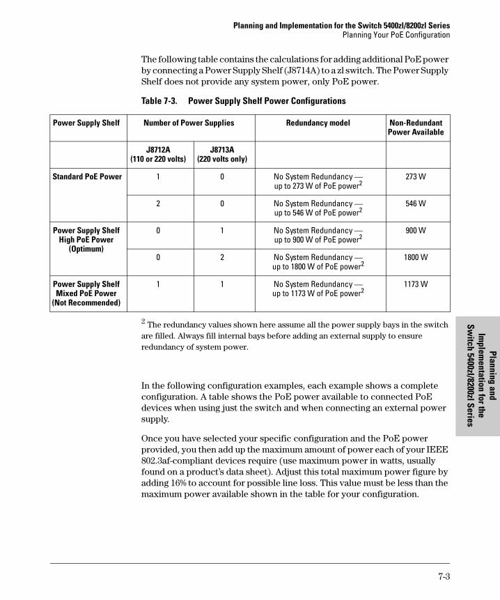
Planning and Implementation for the Switch 5400zl/8200zl SeriesPlanning Your PoE Configuration
Planning and Im
plementation for the
Switch 5400zl/8200zl Series
The following table contains the calculations for adding additional PoE power by connecting a Power Supply Shelf (J8714A) to a zl switch. The Power Supply Shelf does not provide any system power, only PoE power.
Table 7-3. Power Supply Shelf Power Configurations
2 The redundancy values shown here assume all the power supply bays in the switch are filled. Always fill internal bays before adding an external supply to ensure redundancy of system power.
In the following configuration examples, each example shows a complete configuration. A table shows the PoE power available to connected PoE devices when using just the switch and when connecting an external power supply.
Once you have selected your specific configuration and the PoE power provided, you then add up the maximum amount of power each of your IEEE 802.3af-compliant devices require (use maximum power in watts, usually found on a product’s data sheet). Adjust this total maximum power figure by adding 16% to account for possible line loss. This value must be less than the maximum power available shown in the table for your configuration.
Power Supply Shelf Number of Power Supplies Redundancy model Non-Redundant Power Available
J8712A(110 or 220 volts)
J8713A(220 volts only)
Standard PoE Power 1 0 No System Redundancy — up to 273 W of PoE power2
273 W
2 0 No System Redundancy — up to 546 W of PoE power2
546 W
Power Supply Shelf High PoE Power
(Optimum)
0 1 No System Redundancy — up to 900 W of PoE power2
900 W
0 2 No System Redundancy — up to 1800 W of PoE power2
1800 W
Power Supply Shelf Mixed PoE Power
(Not Recommended)
1 1 No System Redundancy — up to 1173 W of PoE power2
1173 W
7-3
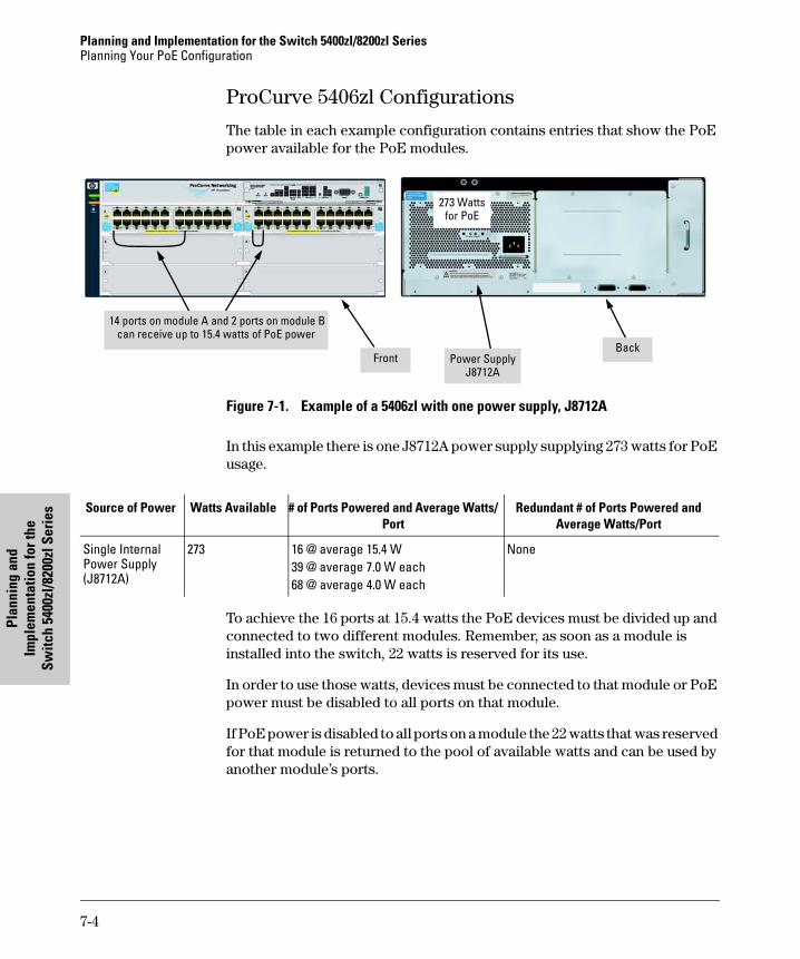
Planning and Implementation for the Switch 5400zl/8200zl SeriesPlanning Your PoE Configuration
Plan
ning
and
Im
plem
enta
tion
for t
he
Switc
h 54
00zl
/820
0zl S
erie
s
ProCurve 5406zl Configurations
The table in each example configuration contains entries that show the PoE power available for the PoE modules.
Figure 7-1. Example of a 5406zl with one power supply, J8712A
In this example there is one J8712A power supply supplying 273 watts for PoE usage.
To achieve the 16 ports at 15.4 watts the PoE devices must be divided up and connected to two different modules. Remember, as soon as a module is installed into the switch, 22 watts is reserved for its use.
In order to use those watts, devices must be connected to that module or PoE power must be disabled to all ports on that module.
If PoE power is disabled to all ports on a module the 22 watts that was reserved for that module is returned to the pool of available watts and can be used by another module’s ports.
14 ports on module A and 2 ports on module B can receive up to 15.4 watts of PoE power
FrontBack
Power SupplyJ8712A
273 Watts for PoE
Source of Power Watts Available # of Ports Powered and Average Watts/Port
Redundant # of Ports Powered and Average Watts/Port
Single Internal Power Supply (J8712A)
273 16 @ average 15.4 W39 @ average 7.0 W each 68 @ average 4.0 W each
None
7-4
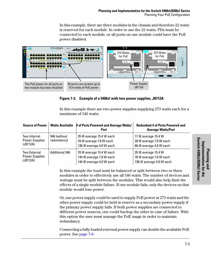
Planning and Implementation for the Switch 5400zl/8200zl SeriesPlanning Your PoE Configuration
Planning and Im
plementation for the
Switch 5400zl/8200zl Series
In this example, there are three modules in the chassis and therefore 22 watts is reserved for each module. In order to use the 22 watts, PDs must be connected to each module, or all ports on one module could have the PoE power disabled.
Figure 7-2. Example of a 5406zl with two power supplies, J8712A
In this example there are two power supplies supplying 273 watts each for a maximum of 546 watts.
In this example the load must be balanced or split between two or three modules in order to effectively use all 546 watts. The number of devices and wattage must be split between the modules. This would also help limit the effects of a single module failure. If one module fails, only the devices on that module would lose power.
Or, one power supply could be used to supply PoE power at 273 watts and the other power supply could be held in reserve as a secondary power supply if the primary power supply fails. If both power supplies are connected to different power sources, one could backup the other in case of failure. With this option the user must manage the PoE usage in order to maintain redundancy.
Connecting a fully loaded external power supply can double the available PoE power. See page 7-9.
35 ports can receive up to 15.4 watts of PoE power
The PoE power for all ports on this module has been disabled
Power SupplyJ8712A
273 Watts for PoE
273 Watts for PoE
Source of Power Watts Available # of Ports Powered and Average Watts/Port
Redundant # of Ports Powered and Average Watts/Port
Two Internal Power Supplies (J8712A)
546 (without redundancy)
35 @ average 15.4 W each78 @ average 7.0 W each136 @ average 4.0 W each
17 @ average 15.4 W39 @ average 7.0 W each 68 @ average 4.0 W each
Two External Power Supplies (J8712A)
Additional 546 70 @ average 15.4 W each144 @ average 7.0 W each144 @ average 4.0 W each
35 @ average 15.4 W78 @ average 7.0 W each 136 @ average 4.0 W each
7-5
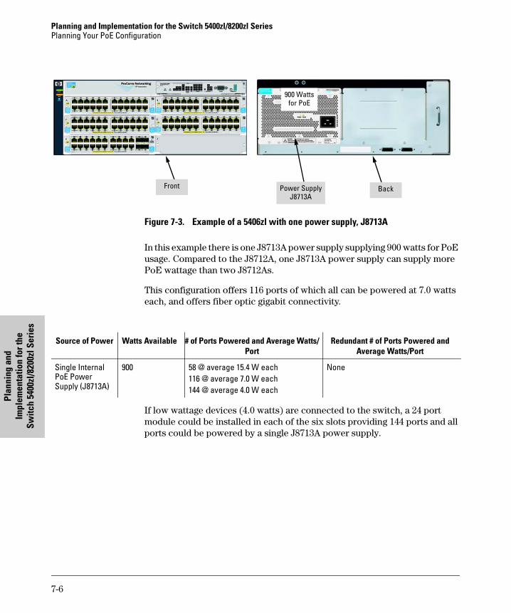
Planning and Implementation for the Switch 5400zl/8200zl SeriesPlanning Your PoE Configuration
Plan
ning
and
Im
plem
enta
tion
for t
he
Switc
h 54
00zl
/820
0zl S
erie
s
Figure 7-3. Example of a 5406zl with one power supply, J8713A
In this example there is one J8713A power supply supplying 900 watts for PoE usage. Compared to the J8712A, one J8713A power supply can supply more PoE wattage than two J8712As.
This configuration offers 116 ports of which all can be powered at 7.0 watts each, and offers fiber optic gigabit connectivity.
If low wattage devices (4.0 watts) are connected to the switch, a 24 port module could be installed in each of the six slots providing 144 ports and all ports could be powered by a single J8713A power supply.
BackPower SupplyJ8713A
Front
900 Watts for PoE
Source of Power Watts Available # of Ports Powered and Average Watts/Port
Redundant # of Ports Powered and Average Watts/Port
Single Internal PoE Power Supply (J8713A)
900 58 @ average 15.4 W each116 @ average 7.0 W each 144 @ average 4.0 W each
None
7-6
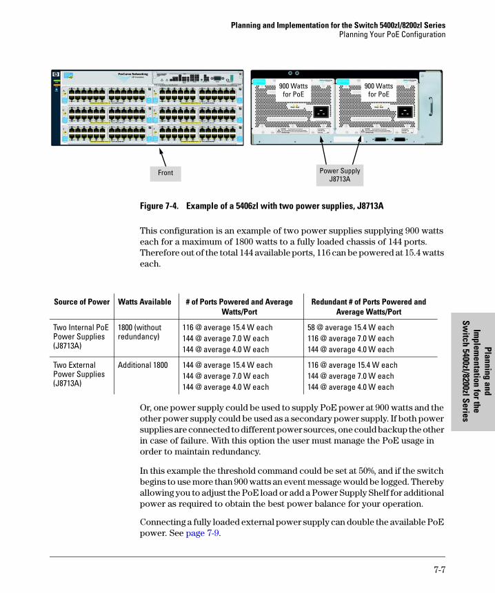
Planning and Implementation for the Switch 5400zl/8200zl SeriesPlanning Your PoE Configuration
Planning and Im
plementation for the
Switch 5400zl/8200zl Series
Figure 7-4. Example of a 5406zl with two power supplies, J8713A
This configuration is an example of two power supplies supplying 900 watts each for a maximum of 1800 watts to a fully loaded chassis of 144 ports. Therefore out of the total 144 available ports, 116 can be powered at 15.4 watts each.
Or, one power supply could be used to supply PoE power at 900 watts and the other power supply could be used as a secondary power supply. If both power supplies are connected to different power sources, one could backup the other in case of failure. With this option the user must manage the PoE usage in order to maintain redundancy.
In this example the threshold command could be set at 50%, and if the switch begins to use more than 900 watts an event message would be logged. Thereby allowing you to adjust the PoE load or add a Power Supply Shelf for additional power as required to obtain the best power balance for your operation.
Connecting a fully loaded external power supply can double the available PoE power. See page 7-9.
Power SupplyJ8713A
Front
900 Watts for PoE
900 Watts for PoE
Source of Power Watts Available # of Ports Powered and Average Watts/Port
Redundant # of Ports Powered and Average Watts/Port
Two Internal PoE Power Supplies (J8713A)
1800 (without redundancy)
116 @ average 15.4 W each144 @ average 7.0 W each144 @ average 4.0 W each
58 @ average 15.4 W each116 @ average 7.0 W each 144 @ average 4.0 W each
Two External Power Supplies (J8713A)
Additional 1800 144 @ average 15.4 W each144 @ average 7.0 W each144 @ average 4.0 W each
116 @ average 15.4 W each144 @ average 7.0 W each144 @ average 4.0 W each
7-7
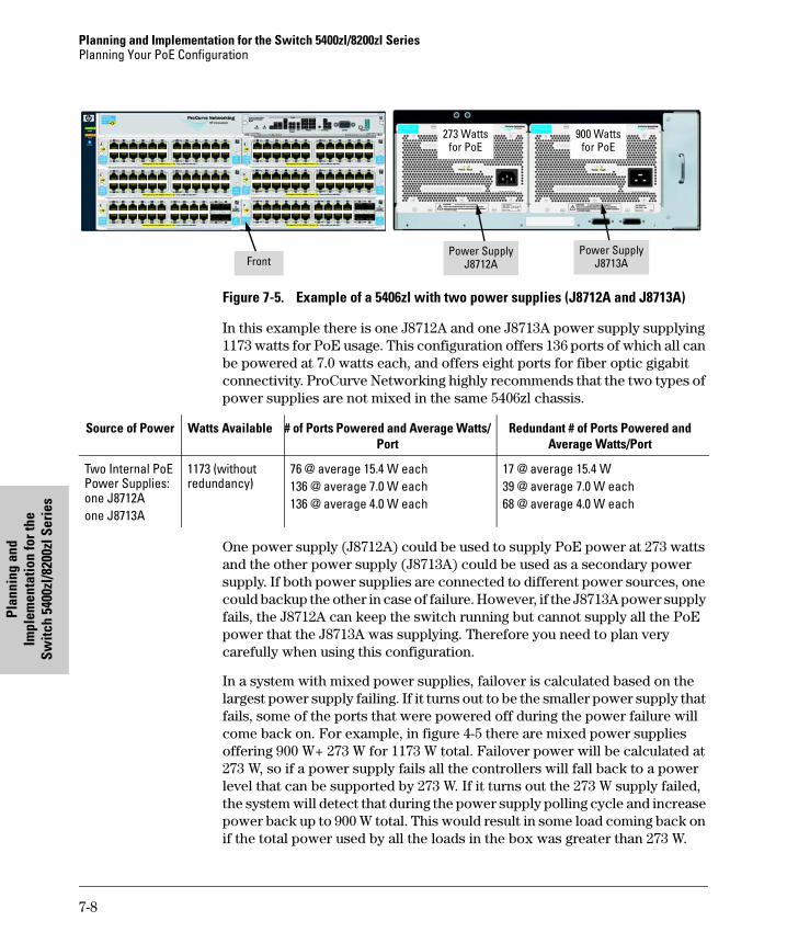
Planning and Implementation for the Switch 5400zl/8200zl SeriesPlanning Your PoE Configuration
Plan
ning
and
Im
plem
enta
tion
for t
he
Switc
h 54
00zl
/820
0zl S
erie
s
Figure 7-5. Example of a 5406zl with two power supplies (J8712A and J8713A)
In this example there is one J8712A and one J8713A power supply supplying 1173 watts for PoE usage. This configuration offers 136 ports of which all can be powered at 7.0 watts each, and offers eight ports for fiber optic gigabit connectivity. ProCurve Networking highly recommends that the two types of power supplies are not mixed in the same 5406zl chassis.
One power supply (J8712A) could be used to supply PoE power at 273 watts and the other power supply (J8713A) could be used as a secondary power supply. If both power supplies are connected to different power sources, one could backup the other in case of failure. However, if the J8713A power supply fails, the J8712A can keep the switch running but cannot supply all the PoE power that the J8713A was supplying. Therefore you need to plan very carefully when using this configuration.
In a system with mixed power supplies, failover is calculated based on the largest power supply failing. If it turns out to be the smaller power supply that fails, some of the ports that were powered off during the power failure will come back on. For example, in figure 4-5 there are mixed power supplies offering 900 W+ 273 W for 1173 W total. Failover power will be calculated at 273 W, so if a power supply fails all the controllers will fall back to a power level that can be supported by 273 W. If it turns out the 273 W supply failed, the system will detect that during the power supply polling cycle and increase power back up to 900 W total. This would result in some load coming back on if the total power used by all the loads in the box was greater than 273 W.
Power SupplyJ8712AFront
Power SupplyJ8713A
273 Watts for PoE
900 Watts for PoE
Source of Power Watts Available # of Ports Powered and Average Watts/Port
Redundant # of Ports Powered and Average Watts/Port
Two Internal PoE Power Supplies: one J8712A one J8713A
1173 (without redundancy)
76 @ average 15.4 W each 136 @ average 7.0 W each 136 @ average 4.0 W each
17 @ average 15.4 W39 @ average 7.0 W each 68 @ average 4.0 W each
7-8
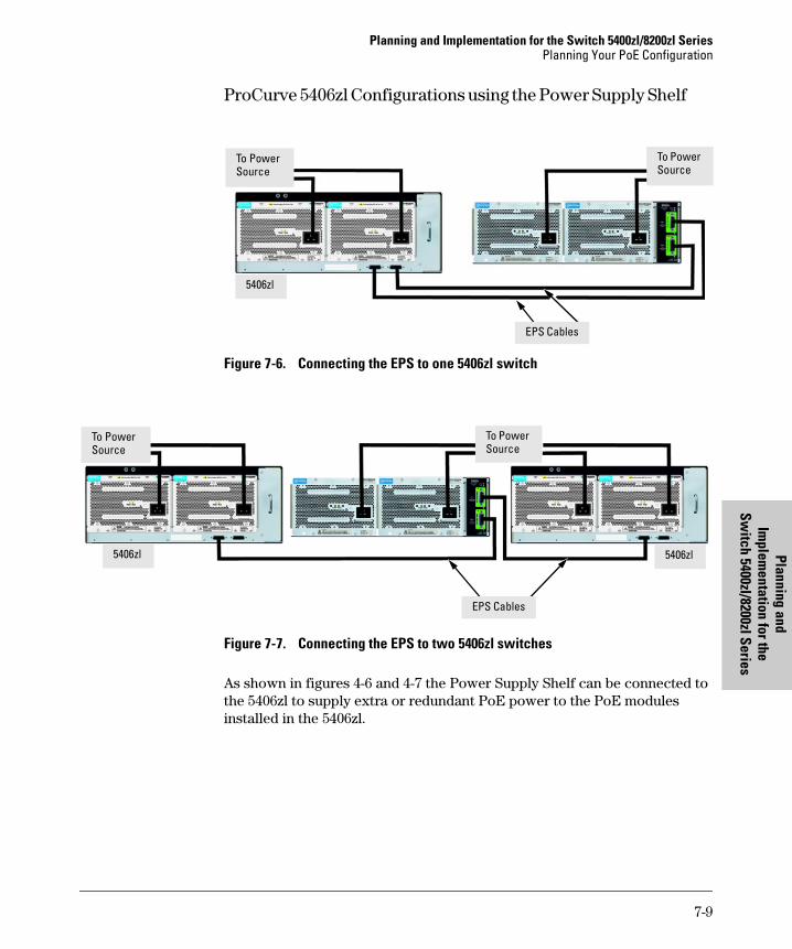
Planning and Implementation for the Switch 5400zl/8200zl SeriesPlanning Your PoE Configuration
Planning and Im
plementation for the
Switch 5400zl/8200zl Series
ProCurve 5406zl Configurations using the Power Supply Shelf
Figure 7-6. Connecting the EPS to one 5406zl switch
Figure 7-7. Connecting the EPS to two 5406zl switches
As shown in figures 4-6 and 4-7 the Power Supply Shelf can be connected to the 5406zl to supply extra or redundant PoE power to the PoE modules installed in the 5406zl.
To Power Source
EPS Cables
To Power Source
5406zl
EPS Cables
5406zl 5406zl
To Power Source
To Power Source
7-9
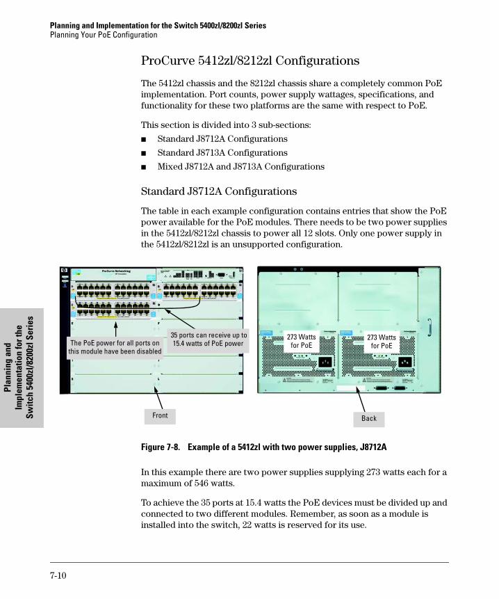
Planning and Implementation for the Switch 5400zl/8200zl SeriesPlanning Your PoE Configuration
Plan
ning
and
Im
plem
enta
tion
for t
he
Switc
h 54
00zl
/820
0zl S
erie
s
ProCurve 5412zl/8212zl Configurations
The 5412zl chassis and the 8212zl chassis share a completely common PoE implementation. Port counts, power supply wattages, specifications, and functionality for these two platforms are the same with respect to PoE.
This section is divided into 3 sub-sections:
■ Standard J8712A Configurations
■ Standard J8713A Configurations
■ Mixed J8712A and J8713A Configurations
Standard J8712A Configurations
The table in each example configuration contains entries that show the PoE power available for the PoE modules. There needs to be two power supplies in the 5412zl/8212zl chassis to power all 12 slots. Only one power supply in the 5412zl/8212zl is an unsupported configuration.
Figure 7-8. Example of a 5412zl with two power supplies, J8712A
In this example there are two power supplies supplying 273 watts each for a maximum of 546 watts.
To achieve the 35 ports at 15.4 watts the PoE devices must be divided up and connected to two different modules. Remember, as soon as a module is installed into the switch, 22 watts is reserved for its use.
35 ports can receive up to 15.4 watts of PoE powerThe PoE power for all ports on
this module have been disabled
273 Watts for PoE
273 Watts for PoE
BackFront
7-10

Planning and Implementation for the Switch 5400zl/8200zl SeriesPlanning Your PoE Configuration
Planning and Im
plementation for the
Switch 5400zl/8200zl Series
In order to use those watts, devices must be connected to that module or PoE power must be disabled to all ports on that module.
If PoE power is disabled to all ports on a module the 22 watts that was reserved for that module is returned to the pool of available watts and can be used by another module’s ports.
In this example the load must be balanced or split between two or three modules in order to effectively use all 546 watts. The number of devices and wattage must be split between the modules. This would also help limit the effects of a single module failure. If one module fails, only the devices on that module would lose power.
In this example, there are three modules in the chassis and therefore 22 watts is reserved for each module. In order to use the 22 watts, PDs must be connected to each module. Or all ports on one module could have the PoE power disabled.
Also in this configuration, there is no redundant power. Should a power supply fail, the remaining power supply can keep the switch running, but cannot supply all the PoE power needed by the modules.
Source of Power Watts Available # of Ports Powered and Average Watts/Port
Redundant # of Ports Powered and Average Watts/Port
Two Internal Power Supplies (J8712A)
546 (without redundancy)
35 @ average 15.4 W each78 @ average 7.0 W each136 @ average 4.0 W each
None
7-11
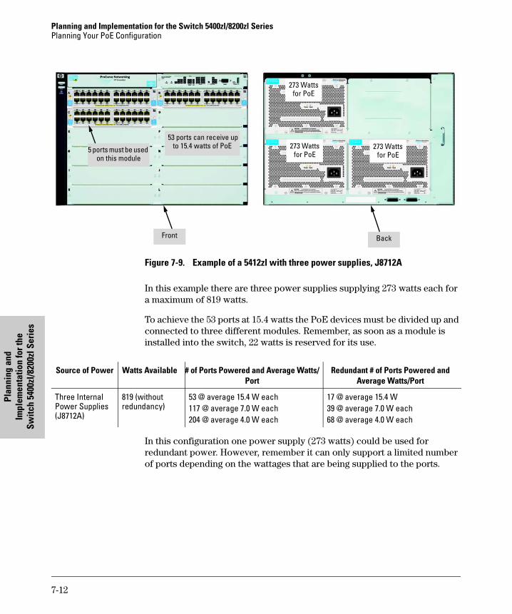
Planning and Implementation for the Switch 5400zl/8200zl SeriesPlanning Your PoE Configuration
Plan
ning
and
Im
plem
enta
tion
for t
he
Switc
h 54
00zl
/820
0zl S
erie
s
Figure 7-9. Example of a 5412zl with three power supplies, J8712A
In this example there are three power supplies supplying 273 watts each for a maximum of 819 watts.
To achieve the 53 ports at 15.4 watts the PoE devices must be divided up and connected to three different modules. Remember, as soon as a module is installed into the switch, 22 watts is reserved for its use.
In this configuration one power supply (273 watts) could be used for redundant power. However, remember it can only support a limited number of ports depending on the wattages that are being supplied to the ports.
53 ports can receive up to 15.4 watts of PoE
273 Watts for PoE
273 Watts for PoE
273 Watts for PoE
BackFront
5 ports must be used on this module
Source of Power Watts Available # of Ports Powered and Average Watts/Port
Redundant # of Ports Powered and Average Watts/Port
Three Internal Power Supplies (J8712A)
819 (without redundancy)
53 @ average 15.4 W each117 @ average 7.0 W each204 @ average 4.0 W each
17 @ average 15.4 W39 @ average 7.0 W each 68 @ average 4.0 W each
7-12
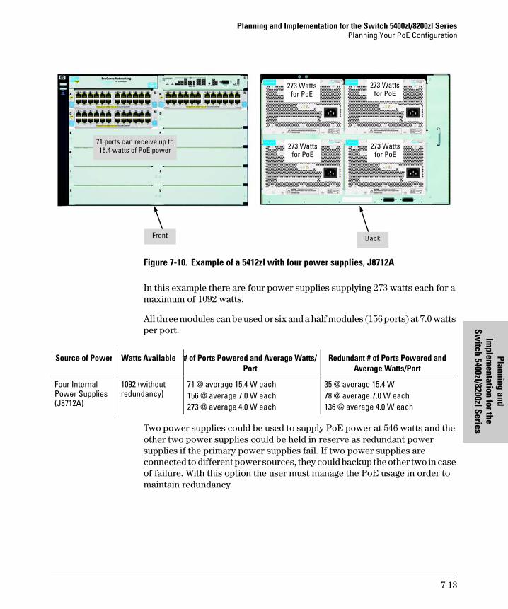
Planning and Implementation for the Switch 5400zl/8200zl SeriesPlanning Your PoE Configuration
Planning and Im
plementation for the
Switch 5400zl/8200zl Series
Figure 7-10. Example of a 5412zl with four power supplies, J8712A
In this example there are four power supplies supplying 273 watts each for a maximum of 1092 watts.
All three modules can be used or six and a half modules (156 ports) at 7.0 watts per port.
Two power supplies could be used to supply PoE power at 546 watts and the other two power supplies could be held in reserve as redundant power supplies if the primary power supplies fail. If two power supplies are connected to different power sources, they could backup the other two in case of failure. With this option the user must manage the PoE usage in order to maintain redundancy.
71 ports can receive up to 15.4 watts of PoE power
BackFront
273 Watts for PoE
273 Watts for PoE
273 Watts for PoE
273 Watts for PoE
Source of Power Watts Available # of Ports Powered and Average Watts/Port
Redundant # of Ports Powered and Average Watts/Port
Four Internal Power Supplies (J8712A)
1092 (without redundancy)
71 @ average 15.4 W each156 @ average 7.0 W each273 @ average 4.0 W each
35 @ average 15.4 W78 @ average 7.0 W each 136 @ average 4.0 W each
7-13
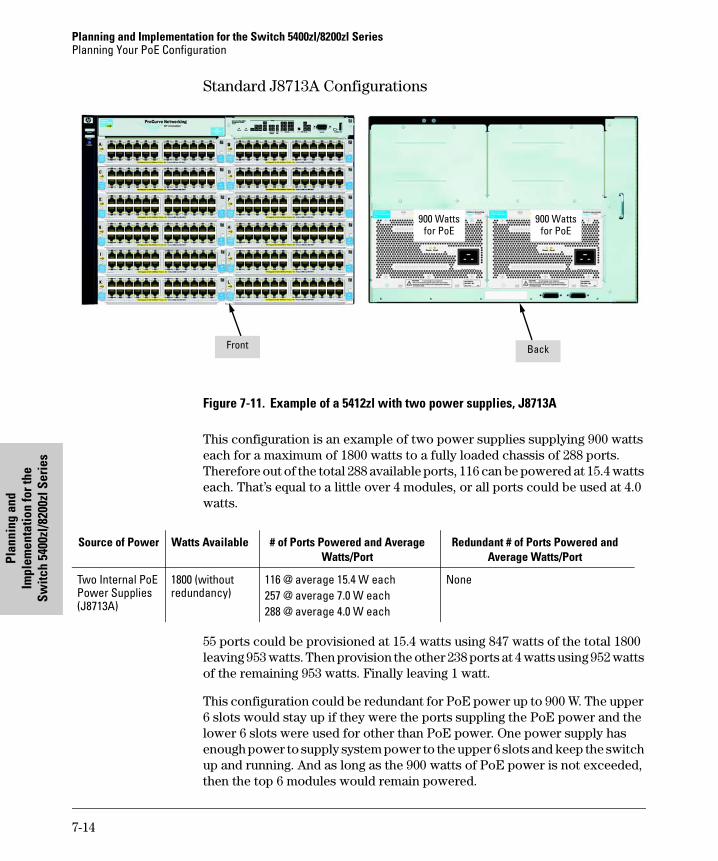
Planning and Implementation for the Switch 5400zl/8200zl SeriesPlanning Your PoE Configuration
Plan
ning
and
Im
plem
enta
tion
for t
he
Switc
h 54
00zl
/820
0zl S
erie
s
Standard J8713A Configurations
Figure 7-11. Example of a 5412zl with two power supplies, J8713A
This configuration is an example of two power supplies supplying 900 watts each for a maximum of 1800 watts to a fully loaded chassis of 288 ports. Therefore out of the total 288 available ports, 116 can be powered at 15.4 watts each. That’s equal to a little over 4 modules, or all ports could be used at 4.0 watts.
55 ports could be provisioned at 15.4 watts using 847 watts of the total 1800 leaving 953 watts. Then provision the other 238 ports at 4 watts using 952 watts of the remaining 953 watts. Finally leaving 1 watt.
This configuration could be redundant for PoE power up to 900 W. The upper 6 slots would stay up if they were the ports suppling the PoE power and the lower 6 slots were used for other than PoE power. One power supply has enough power to supply system power to the upper 6 slots and keep the switch up and running. And as long as the 900 watts of PoE power is not exceeded, then the top 6 modules would remain powered.
BackFront
900 Watts for PoE
900 Watts for PoE
Source of Power Watts Available # of Ports Powered and Average Watts/Port
Redundant # of Ports Powered and Average Watts/Port
Two Internal PoE Power Supplies (J8713A)
1800 (without redundancy)
116 @ average 15.4 W each257 @ average 7.0 W each288 @ average 4.0 W each
None
7-14
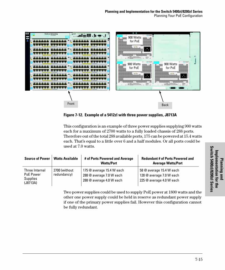
Planning and Implementation for the Switch 5400zl/8200zl SeriesPlanning Your PoE Configuration
Planning and Im
plementation for the
Switch 5400zl/8200zl Series
Figure 7-12. Example of a 5412zl with three power supplies, J8713A
This configuration is an example of three power supplies supplying 900 watts each for a maximum of 2700 watts to a fully loaded chassis of 288 ports. Therefore out of the total 288 available ports, 175 can be powered at 15.4 watts each. That’s equal to a little over 6 and a half modules. Or all ports could be used at 7.0 watts.
Two power supplies could be used to supply PoE power at 1800 watts and the other one power supply could be held in reserve as redundant power supply if one of the primary power supplies fail. However this configuration cannot be fully redundant.
BackFront
900 Watts for PoE
900 Watts for PoE
900 Watts for PoE
Source of Power Watts Available # of Ports Powered and Average Watts/Port
Redundant # of Ports Powered and Average Watts/Port
Three Internal PoE Power Supplies (J8713A)
2700 (without redundancy)
175 @ average 15.4 W each288 @ average 7.0 W each288 @ average 4.0 W each
58 @ average 15.4 W each128 @ average 7.0 W each 225 @ average 4.0 W each
7-15
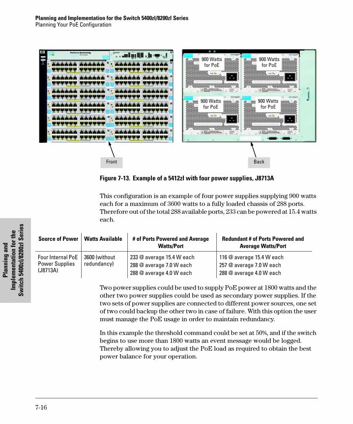
Planning and Implementation for the Switch 5400zl/8200zl SeriesPlanning Your PoE Configuration
Plan
ning
and
Im
plem
enta
tion
for t
he
Switc
h 54
00zl
/820
0zl S
erie
s
Figure 7-13. Example of a 5412zl with four power supplies, J8713A
This configuration is an example of four power supplies supplying 900 watts each for a maximum of 3600 watts to a fully loaded chassis of 288 ports. Therefore out of the total 288 available ports, 233 can be powered at 15.4 watts each.
Two power supplies could be used to supply PoE power at 1800 watts and the other two power supplies could be used as secondary power supplies. If the two sets of power supplies are connected to different power sources, one set of two could backup the other two in case of failure. With this option the user must manage the PoE usage in order to maintain redundancy.
In this example the threshold command could be set at 50%, and if the switch begins to use more than 1800 watts an event message would be logged. Thereby allowing you to adjust the PoE load as required to obtain the best power balance for your operation.
BackFront
900 Watts for PoE
900 Watts for PoE
900 Watts for PoE
900 Watts for PoE
Source of Power Watts Available # of Ports Powered and Average Watts/Port
Redundant # of Ports Powered and Average Watts/Port
Four Internal PoE Power Supplies (J8713A)
3600 (without redundancy)
233 @ average 15.4 W each288 @ average 7.0 W each288 @ average 4.0 W each
116 @ average 15.4 W each257 @ average 7.0 W each 288 @ average 4.0 W each
7-16
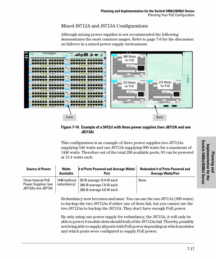
Planning and Implementation for the Switch 5400zl/8200zl SeriesPlanning Your PoE Configuration
Planning and Im
plementation for the
Switch 5400zl/8200zl Series
Mixed J8712A and J8713A Configurations
Although mixing power supplies is not recommended the following demonstrates the most common usages. Refer to page 7-8 for the discussion on failover in a mixed power supply environment.
Figure 7-14. Example of a 5412zl with three power supplies (two J8712A and one J8713A)
This configuration is an example of three power supplies two J8712As supplying 546 watts and one J8713A supplying 900 watts for a maximum of 1446 watts. Therefore out of the total 288 available ports, 93 can be powered at 15.4 watts each.
Redundancy now becomes and issue. You can use the one J8713A (900 watts) to backup the two J8712As if either one of them fail, but you cannot use the two J8712As to backup the J8713A. They don’t have enough PoE power.
By only using one power supply for redundancy, the J8713A, it will only be able to power 6 module slots should both of the J8712As fail. Thereby, possibly not being able to supply all ports with PoE power depending on which modules and which ports were configured to supply PoE power.
BackFront
273 Watts for PoE
273 Watts for PoE
900 Watts for PoE
Source of Power Watts Available
# of Ports Powered and Average Watts/Port
Redundant # of Ports Powered and Average Watts/Port
Three Internal PoE Power Supplies: two J8712As one J8713A
1446 (without redundancy)
93 @ average 15.4 W each 206 @ average 7.0 W each 288 @ average 4.0 W each
None
7-17
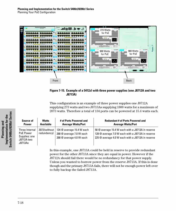
Planning and Implementation for the Switch 5400zl/8200zl SeriesPlanning Your PoE Configuration
Plan
ning
and
Im
plem
enta
tion
for t
he
Switc
h 54
00zl
/820
0zl S
erie
s
Figure 7-15. Example of a 5412zl with three power supplies (one J8712A and two J8713A)
This configuration is an example of three power supplies one J8712A supplying 273 watts and two J8713As supplying 1800 watts for a maximum of 2073 watts. Therefore a total of 134 ports can be powered at 15.4 watts each.
In this example, one J8713A could be held in reserve to provide redundant power for the other J8713A since they are equal in power. However if the J8712A should fail there would be no redundancy for that power supply. Unless you wanted to borrow power from the reserve J8713A. If this is done though and the primary J8713A fails, there will not be enough power left over to fully backup the failed J8713A.
BackFront
900 Watts for PoE
900 Watts for PoE
273 Watts for PoE
Source of Power
WattsAvailable
# of Ports Powered andAverage Watts/Port
Redundant # of Ports Powered andAverage Watts/Port
Three Internal PoE Power Supplies: one J8712A two J8713As
2073 (without redundancy)
134 @ average 15.4 W each 288 @ average 7.0 W each 288 @ average 4.0 W each
58 @ average 15.4 W each with a J8713A in reserve128 @ average 7.0 W each with a J8713A in reserve225 @ average 4.0 W each with a J8713A in reserve
7-18
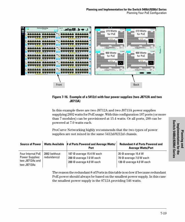
Planning and Implementation for the Switch 5400zl/8200zl SeriesPlanning Your PoE Configuration
Planning and Im
plementation for the
Switch 5400zl/8200zl Series
Figure 7-16. Example of a 5412zl with four power supplies (two J8712A and two J8713A)
In this example there are two J8712A and two J8713A power supplies supplying 2892 watts for PoE usage. With this configuration 187 ports (or more than 7 modules) can be provisioned at 15.4 watts. Or all ports, 288 can be powered at 7.0 watts each.
ProCurve Networking highly recommends that the two types of power supplies are not mixed in the same 5412zl/8212zl chassis.
The reason the redundant # of Ports in this table is so low if because redundant PoE power should always be based on the smallest power supply. In this case the smallest power supply is the 8712A providing 546 watts.
BackFront
900 Watts for PoE
900 Watts for PoE
273 Watts for PoE
273 Watts for PoE
Source of Power Watts Available # of Ports Powered and Average Watts/Port
Redundant # of Ports Powered and Average Watts/Port
Four Internal PoE Power Supplies: two J8712As andtwo J8713As
2892 (without redundancy)
187 @ average 15.4 W each 288 @ average 7.0 W each 288 @ average 4.0 W each
35 @ average 15.4 W78 @ average 7.0 W each 136 @ average 4.0 W each
7-19
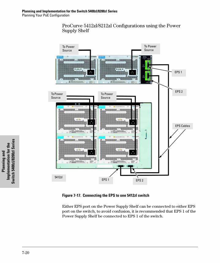
Planning and Implementation for the Switch 5400zl/8200zl SeriesPlanning Your PoE Configuration
Plan
ning
and
Im
plem
enta
tion
for t
he
Switc
h 54
00zl
/820
0zl S
erie
s
ProCurve 5412zl/8212zl Configurations using the PowerSupply Shelf
Figure 7-17. Connecting the EPS to one 5412zl switch
Either EPS port on the Power Supply Shelf can be connected to either EPS port on the switch, to avoid confusion, it is recommended that EPS 1 of the Power Supply Shelf be connected to EPS 1 of the switch.
To Power Source
EPS Cables
To Power Source
5412zl
To Power Source
To Power Source
EPS 2EPS 1
EPS 2
EPS 1
7-20
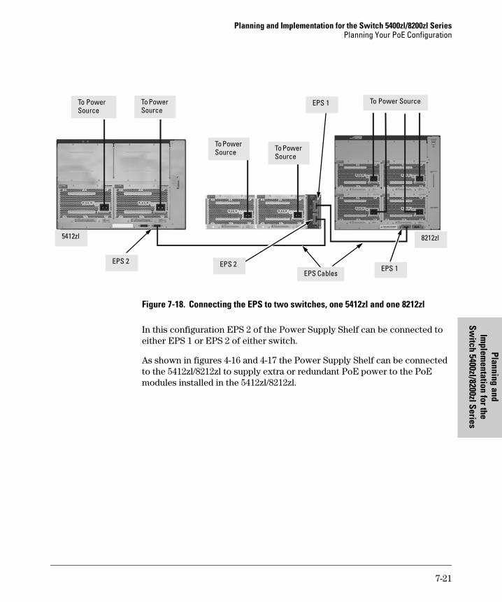
Planning and Implementation for the Switch 5400zl/8200zl SeriesPlanning Your PoE Configuration
Planning and Im
plementation for the
Switch 5400zl/8200zl Series
Figure 7-18. Connecting the EPS to two switches, one 5412zl and one 8212zl
In this configuration EPS 2 of the Power Supply Shelf can be connected to either EPS 1 or EPS 2 of either switch.
As shown in figures 4-16 and 4-17 the Power Supply Shelf can be connected to the 5412zl/8212zl to supply extra or redundant PoE power to the PoE modules installed in the 5412zl/8212zl.
To Power Source
To Power Source
To Power Source
To Power Source
To Power Source
EPS CablesEPS 1
EPS 2 EPS 2
EPS 1
5412zl 8212zl
7-21

Infrastructure Requirements
8
Infrastructure Requirements
Air conditioning
Power supplies create a great amount of heat. Ensure you have enough cool air to maintain an ambient temperature between 0°C to 50°C (32°F to 131°F) around the switch devices inside the rack or equipment closet. If you are installing any of the X2 transceivers the operating ambient temperature should not exceed 40°C (104°F). See transceiver specifications in the installation guide for your switch.
A typical 48 port PoE switch BTU rating is approximately 920. Adding in a maximum number of PoE powered devices (PD) connected to the switch at 15.4 watts, the BTU rating can jump to approximately 2280. Although typically the PDs are outside of the data closet area, the total BTU needs of the air conditioning system (for the whole building for example) needs to take this additional cooling requirement into consideration.
When adding a Redundant Power Supply (RPS), the BTU rating can grow to approximately 3500 and more. This example only takes into consideration one PoE switch with redundant power. As more switches, PoE PDs, and redundant power supplies are added the BTU rating increases requiring more cooling.
Ensure wiring closets and other areas where PoE switches and power supplies are congregated have proper cooling. Even though most PDs do not draw the maximum 15.4 watts, it is still good to plan for the maximum.
Power requirements
Ensure you have enough power supplied to the area where the switches will be mounted. Some units have dual power supplies in them that you may want to consider connecting each power supply to different circuits in order to provide redundant power to the switch.
8-1
Infrastructure RequirementsPhysical Space
Infr
astr
uctu
re R
equi
rem
ents
Many switches come with dual power ratings (110 or 220 volt operation). Therefore planning for power requirements is critical. If a wiring closet currently only supplies 110 volts it must be determined whether or not to operate the switch at 110 volts or 220 volts.
You not only need to plan for voltage requirements but amperage requirements. PoE switches can be double or triple the amperage draw compared to a non-PoE switch.
Physical Space
These devices may be deeper (longer) than other equipment in your network due to the added PoE power supplies. Also if RPS units have been added to the rack or wiring closet, ensure enough space has been planned for all devices.
Space around the switch and around the other units must be available to allow:
■ access by service personnel
■ space for power cords and other wiring
■ cool air circulation
Racks
PoE switch devices and RPS units may be heavier than other non-PoE switch devices in your network. Therefore you should rack heavy devices at the bottom of the rack, followed by lighter devices as you move up the rack. This will help to keep the rack from tipping over.
Secure racks as specified by your rack’s manufacturer. Ensure your racks are compliant with any earthquake structural rules and regulations.
8-2

Glossary
Glossary
Glossary
active PoE port - PoE-enabled port connected to a PD and currently delivering power.
priority class - Refers to the type of power prioritization where the switch uses Low (the default), High, and Critical priority assignments to determine which groups of ports will receive power. Note that power priority rules apply only if PoE provisioning on the switch becomes oversubscribed.
EPS - External Power Supply
MPS - Maintenance Power Signature; the signal a PD sends to the switch to indicate that the PD is connected and requires power.
Oversubscribed - The state where there are more PDs requesting PoE power than can be accommodated.
PD - Powered Device. This is an IEEE 802.3af-compliant device that receives its power through a direct connection to a 10/100Base-TX PoE RJ-45 port on the switch. Examples of PDs include Voice-over-IP (VoIP) telephones, wire-less access points, and remote video cameras.
port-number priority - Refers to the type of power prioritization where, within a priority class, the switch assigns the highest priority to the lowest-numbered port, the second-highest priority to the second lowest-numbered port, and so-on. Note that power priority rules apply only if PoE provisioning on the switch becomes oversubscribed.
PoE - Power-Over-Ethernet
PSE - Power-Sourcing Equipment. A PSE, such as the Series 3500yl Switches, or the modules in a 5400zl chassis, provides power to IEEE 802.3af-compliant PDs directly connected to 10/100/1000Base-T PoE RJ-45 ports on the switch. The Series 3500yl Switches and the Switch zl PoE Modules are endpoint PSEs.
Gloss-1

Planning Considerations
A
Planning Considerations
This appendix is divided into three sections:
■ General Considerations
■ Specific Considerations for the 3500yl Switches
■ Specific Considerations for the 5400zl Switches
These lists are in no way exhaustive, however answers to these and other questions will help define how many and what types of switches are needed to implement a PoE configuration.
General Considerations
The following is an example list of considerations during the planning phase no matter which series of switches are being installed:
■ How many devices need PoE power?
■ What devices will need PoE power?
■ How much power will each device require, in watts?
■ What is the total of all their wattages?
■ Will the devices be connected to a 3500yl or to a 5406zl switch?
■ How many ports are needed?
■ How many ports are available?
■ Are the devices to be powered by PoE power supported?
• The ProCurve Switches covered in this manual support any products that meet the IEEE 802.3af PoE standard and some pre-standard PoE devices. For a current list see the FAQ page for your switch, which can be found on the ProCurve Web site, www.procurve.com, Technical Support, FAQs (all).
■ How many PDs per Switch?
• The number of PDs supported per switch depends on the power allocation and how much power each PD uses and how much power is left. The examples in the following section show the power consumption in some typical configurations.
A-1
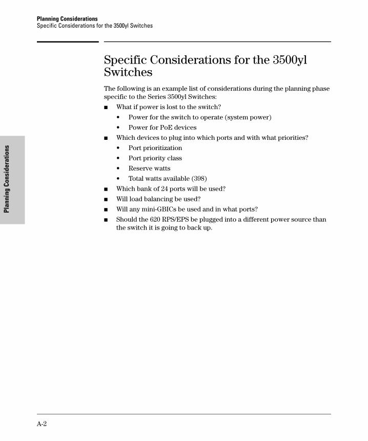
Planning ConsiderationsSpecific Considerations for the 3500yl Switches
Plan
ning
Con
side
ratio
ns
Specific Considerations for the 3500yl SwitchesThe following is an example list of considerations during the planning phase specific to the Series 3500yl Switches:
■ What if power is lost to the switch?
• Power for the switch to operate (system power)
• Power for PoE devices
■ Which devices to plug into which ports and with what priorities?
• Port prioritization
• Port priority class
• Reserve watts
• Total watts available (398)
■ Which bank of 24 ports will be used?
■ Will load balancing be used?
■ Will any mini-GBICs be used and in what ports?
■ Should the 620 RPS/EPS be plugged into a different power source than the switch it is going to back up.
A-2
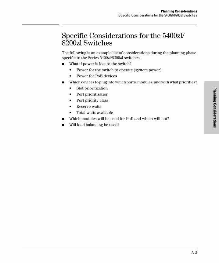
Planning ConsiderationsSpecific Considerations for the 5400zl/8200zl Switches
Planning Considerations
Specific Considerations for the 5400zl/8200zl SwitchesThe following is an example list of considerations during the planning phase specific to the Series 5400zl/8200zl switches:
■ What if power is lost to the switch?
• Power for the switch to operate (system power)
• Power for PoE devices
■ Which devices to plug into which ports, modules, and with what priorities?
• Slot prioritization
• Port prioritization
• Port priority class
• Reserve watts
• Total watts available
■ Which modules will be used for PoE and which will not?
■ Will load balancing be used?
A-3

Index
Index
Numerics
3500yl specific consideration … A-25400/8112zl PoE
enabling, disabling redundancy … 1-135400zl/8200zl specific consideration … A-3
C
cabledata pairs … 1-3power through … 1-3spare pairs … 1-3
class method priority … 2-12
E
EPS power … 1-7example configurations … 3-1, 4-1, 6-1, 7-1
I
internal power supply … 1-12introduction … 1-1
L
line losspower loss … 2-13
LLDP for PoE allocation … 2-7
M
maximum PoEpower … 2-3
maximum power allocations … 2-7–2-8minimum watts … 2-13
O
operating rules … 2-1overview … 1-1
P
PDspower classification
power usage … 2-13planning … 3-1, 4-1, 5-1, 6-1, 7-1planning considerations … A-1PoE … 1-1
capabilitiesproduct capabilities … 1-4
configuration … 6-2considerations planning … A-1planning … 3-1, 4-1, 5-1, 6-1, 7-1power … 2-9power, maximum … 2-3
PoE allocation using LLDP … 2-7port priority … 2-12power loss … 2-13power over ethernet … 1-1power redundancy … 1-12power requirements … 2-13power sourcing equipment … 1-3powered device … 1-3powered devices … 2-13pre-standard devices
disabling … 1-8pre-standard PoE devices … 1-8priority, class method … 2-12priority, port … 2-12ProCurve switch
3500yl-24G-PWR … 1-8, 6-23500yl-48G-PWR … 1-85406zl … 1-105412zl … 1-108212zl … 1-11
ProCurve Switch xl PoE Module … 1-7provisioning power
switch power … 2-2
R
redundancy … 1-13
Index – 1
Inde
x
S
supported products … A-1switch PoE
operation … 2-1switch priority class … 2-14switches
2626-PWR, 2650-PWR, 2600-8-PWR, Series 2600-PWR Switches … 1-5–1-6
2 – Index

stingray.book Page 12 Sunday, November 2, 2003 9:38 AM

Technical information in this documentis subject to change without notice.
© Copyright 2001 - 2008 Hewlett-PackardDevelopment Company, L.P.
January 2008
Manual Part Number
*5991-8574*
5991-8574