Embed Size (px)
Citation preview

Pneumatics Workshop
1

Pneumatics
•Warren Venema– Senior Mechanical Engineering Major at TCNJ– Active in FIRST since 2011
• Alumni of FRC 1403
2
Basic Linear MotionNon Electric
Pneumatics – Air PressureHydraulics – Oil Pressure
•Air is Compressible •Oil is Incompressible
3
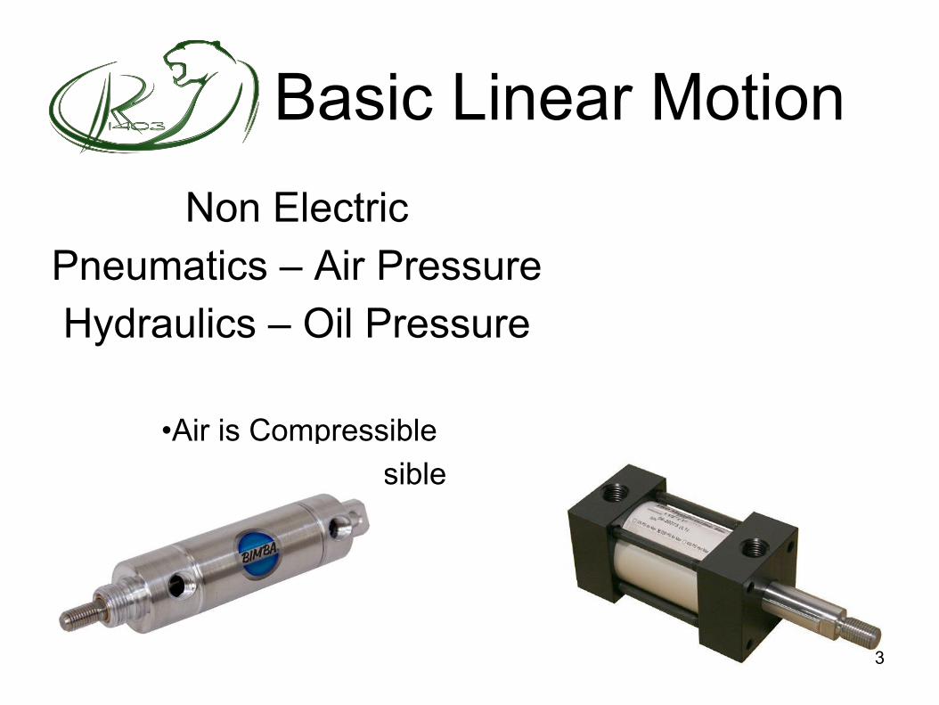
Pressurized air enters port, exerting a force on the piston(psi – pounds per square inch)
Exhaust air is vented
Work is done by the shaft connected to the piston
Primary Function
4
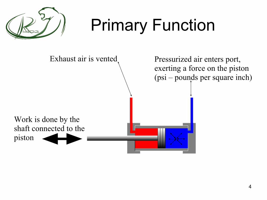
Pneumatics
Force
How much force can the cylinder exert?
Force = air pressure (psi) * piston area (in2)Force = (lb/in2) * in2 = (lb)
5

Pneumatics
Force
How much force can the cylinder exert?
1” Diameter.785 in2
1” Diameter-1/4” Shaft.736 in2
6
Components
Components of a Pneumatic System:● Compressor● Storage Tanks ● Pressure Switch ● Solenoid Valve● Regulator● Fittings● PCN (Pneumatics Control Module)● Relief Valve● Gauge● Tubing● Dump Valve● Actuator or cylinder
7
Compressors
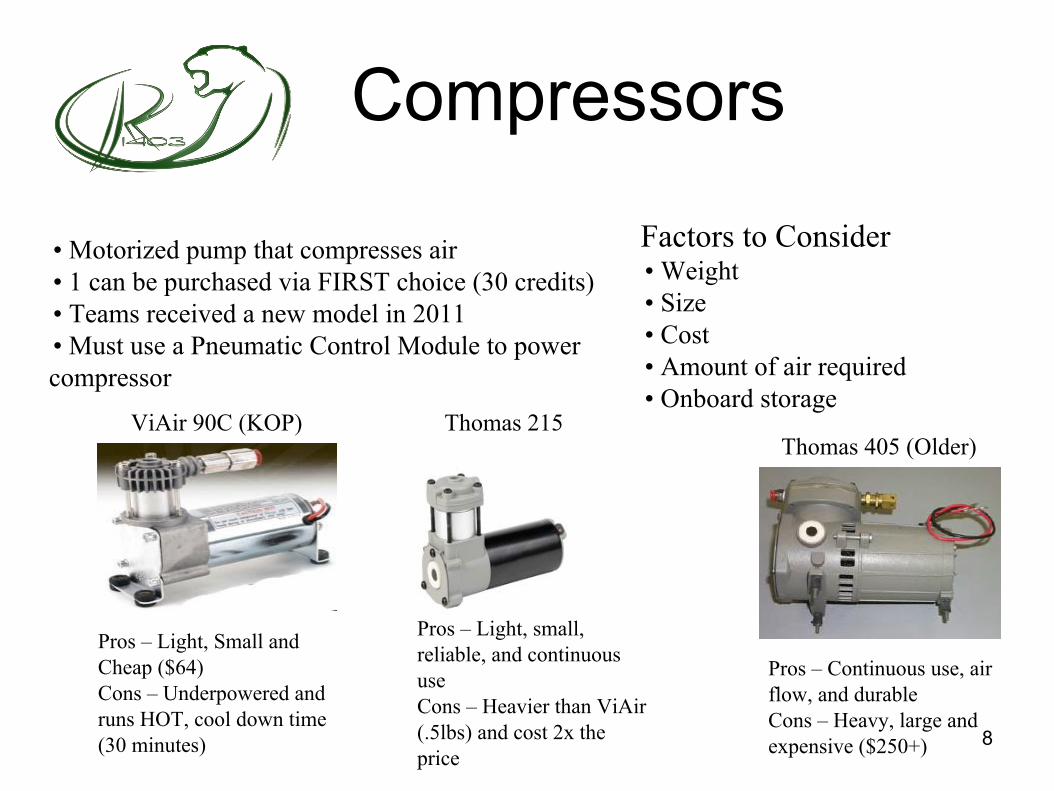
• Motorized pump that compresses air • 1 can be purchased via FIRST choice (30 credits)• Teams received a new model in 2011• Must use a Pneumatic Control Module to power compressor
Thomas 405 (Older)ViAir 90C (KOP) Thomas 215
Pros – Continuous use, air flow, and durableCons – Heavy, large and expensive ($250+)
Pros – Light, Small and Cheap ($64)Cons – Underpowered and runs HOT, cool down time (30 minutes)
Pros – Light, small, reliable, and continuous useCons – Heavier than ViAir (.5lbs) and cost 2x the price
Factors to Consider• Weight• Size• Cost• Amount of air required• Onboard storage
8

Storage Tanks• Tank that holds reserved compressed air• 1 can be purchased via FIRST choice (10 credits)• Mounted before pressure regulator• Must have at least a working pressure of 125 psi • Must have at least a burst pressure of 250 psi
Clippard MetalAndy Mark Plastic Tank (2011)
Pros – Light, cheap ($10), and air volume (more than comparable metal tank)Cons – Limited size and shapes, Plastic or no thread connections
Pros – Durable, shapes, and sizesCons – Heavier and expensive ($28)
Factors to Consider• Weight• Size• Cost• Amount of air required
Clippard Plastic (2015)
Pros – Light, Cheap, Max VolumeCons – Limited Sizes, Push on Conn. Fragile 9
Components
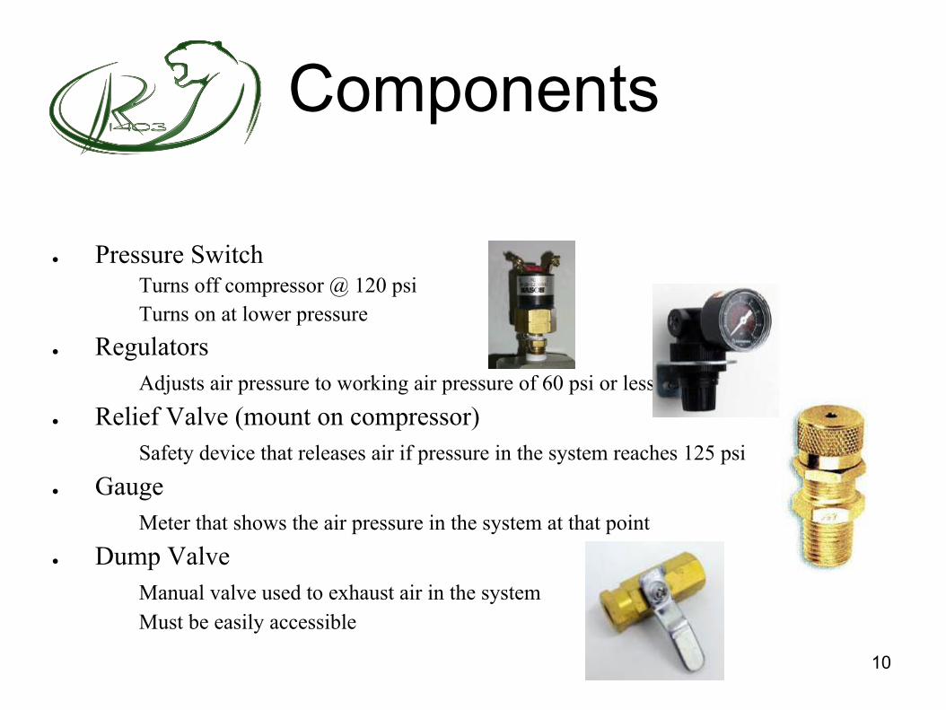
● Pressure Switch Turns off compressor @ 120 psiTurns on at lower pressure
● RegulatorsAdjusts air pressure to working air pressure of 60 psi or less
● Relief Valve (mount on compressor)Safety device that releases air if pressure in the system reaches 125 psi
● GaugeMeter that shows the air pressure in the system at that point
● Dump ValveManual valve used to exhaust air in the systemMust be easily accessible
10

Components Cont.Components of a Pneumatic System:
● Actuator or CylinderDevice that creates mechanical motion
● TubingPlastic hose that carries pressurized airMust have ID of .160”
● FittingsBrass or plastic connectorsUse Teflon tape on threadsfor air tight sealMcMaster-Carr Quick Assembly Brass Compression Tubing
11
Solenoid Valves
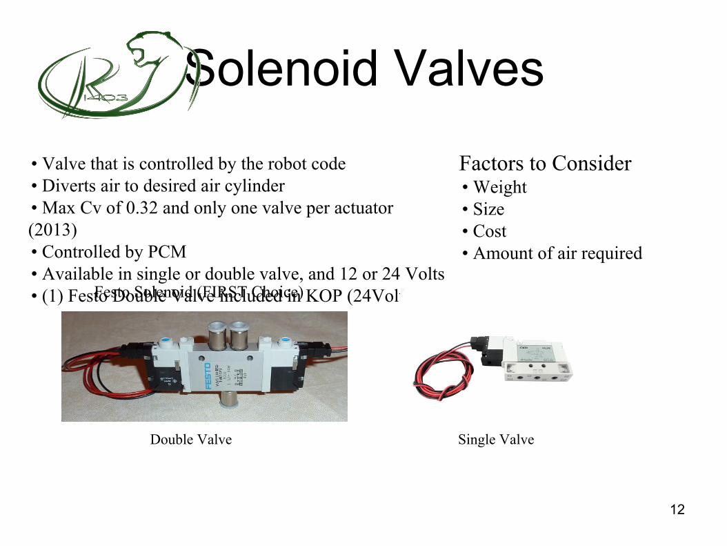
• Valve that is controlled by the robot code • Diverts air to desired air cylinder• Max Cv of 0.32 and only one valve per actuator (2013)• Controlled by PCM• Available in single or double valve, and 12 or 24 Volts• (1) Festo Double Valve included in KOP (24Volts)Festo Solenoid (FIRST Choice)
Double Valve Single Valve
Factors to Consider• Weight• Size• Cost• Amount of air required
12
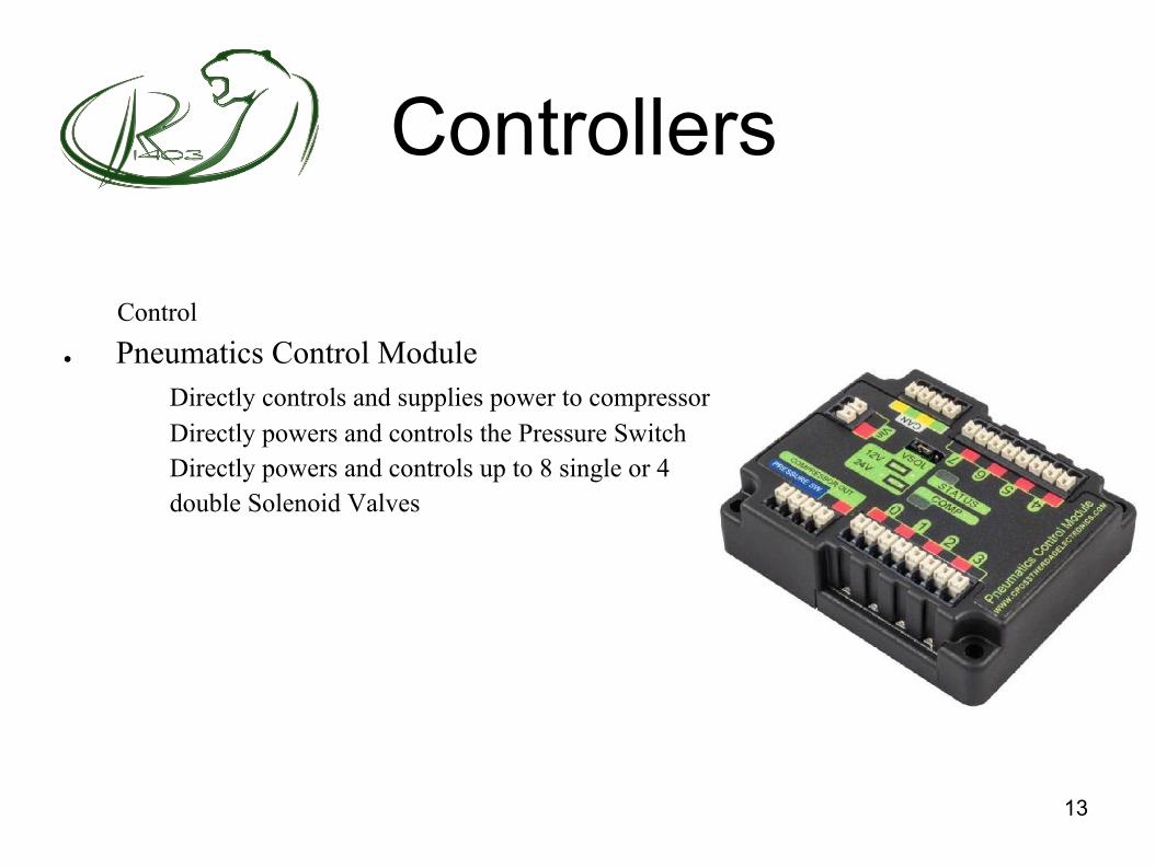
Controllers
Control● Pneumatics Control Module
Directly controls and supplies power to compressorDirectly powers and controls the Pressure SwitchDirectly powers and controls up to 8 single or 4
double Solenoid Valves
13
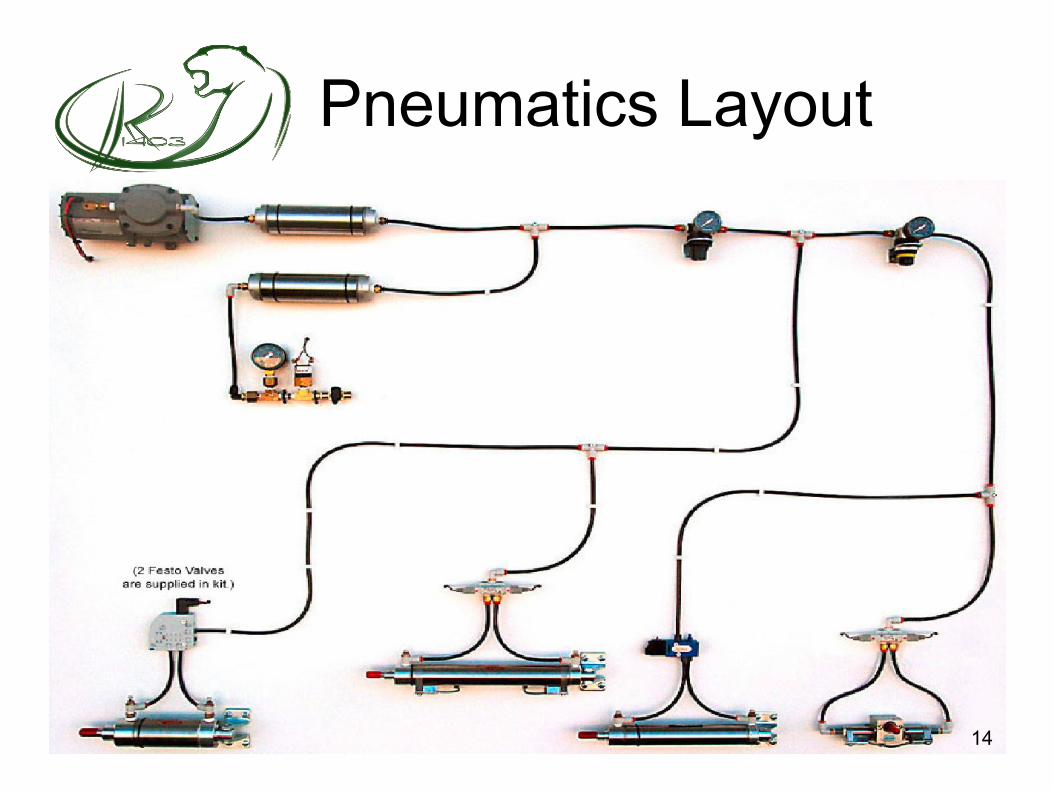
Pneumatics Layout
14
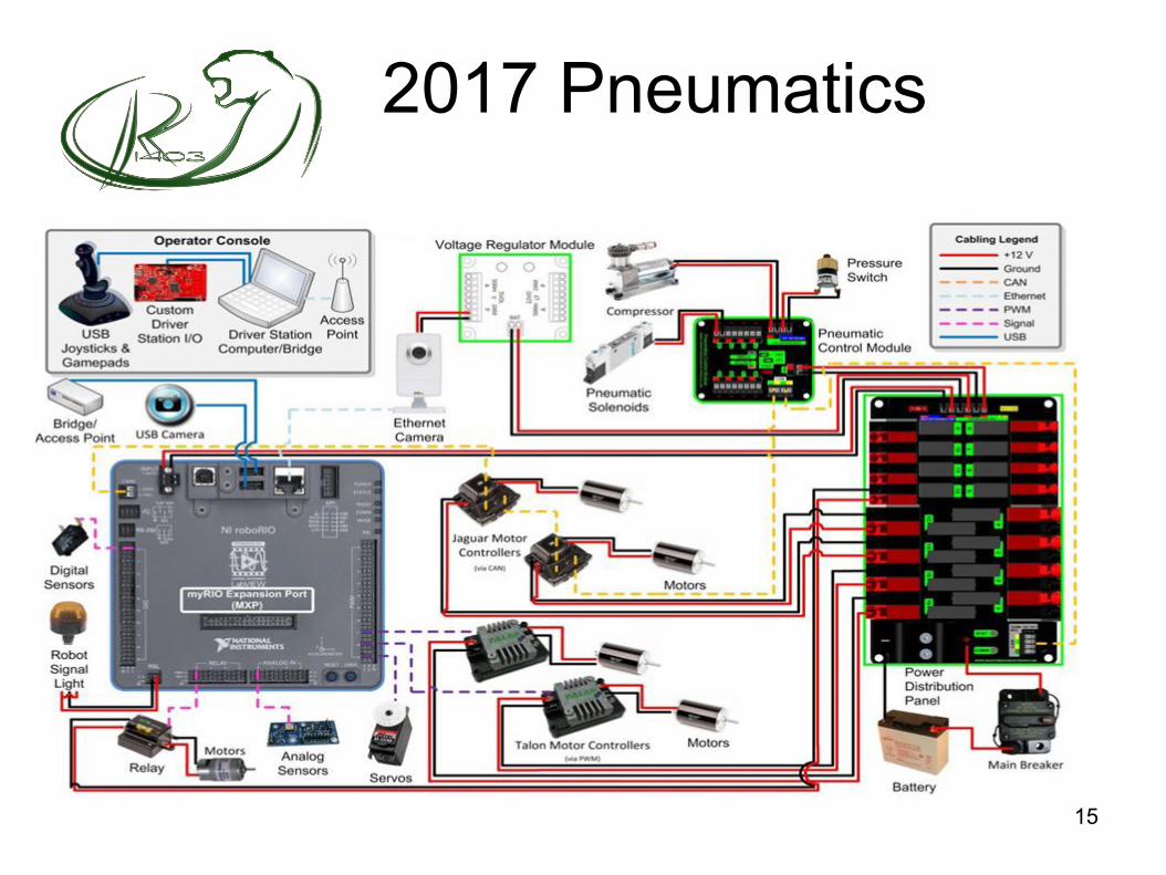
2017 Pneumatics
15

Wiring
After properly setting up your Robo-RIO and all the related electrical equipment the following instructions will result in a working pneumatics systemCompressor1.Wire the compressor to the Pneumatic Control Module (Power)
Pressure Switch1.Connect switch to Pneumatic Control Module (PCM)
ValvesAfter assembly of the kit valves with the included wire we can now wire the solenoid valve to the Pneumatic Control Module Solenoid s (Double Acting Valves only)1.Wire both 1 and 2 from both sides of the valve to the ports on the PCM
16

Pneumatic Control Module
17
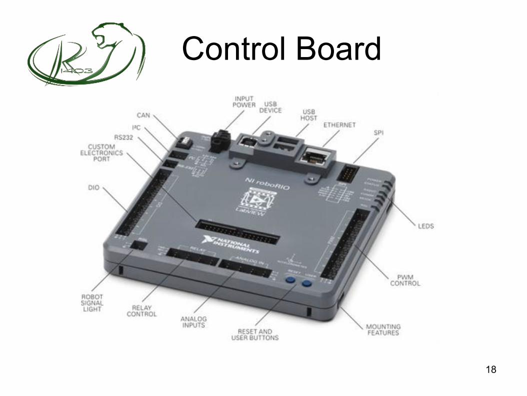
Control Board
18

MountingCylinder allowed to pivot,Avoid side forces
19
Resources / Links• AndyMark inc.
– www.AndyMark.com• Vex Pro
– http://www.vexrobotics.com/vexpro• Chief Delphi
– www.cheifdelphi.com• First Robotics
– www.usfirst.org• Cougar Robotics Team 1403
– http://www.cougarrobotics.com• Robotics Eagles Team 358 (Great Tutorials, Documents, and Step by Steps)
– www.team358.org• Simbotics Team 1114 (Workshops)
– www.simbotics.org 20