Embed Size (px)
Citation preview

Pneumatic Valves
For precision and control
Thanks to Mr D McLaren - RGC - Aberdeen
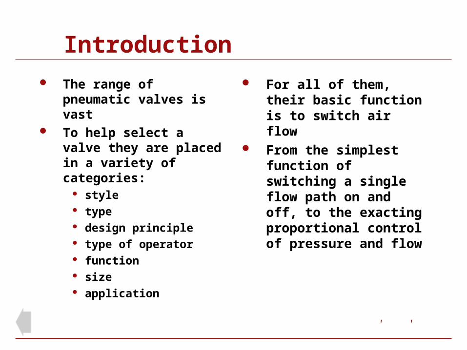
Introduction
The range of pneumatic valves is vast
To help select a valve they are placed in a variety of categories:
style type design principle type of operator function size application
For all of them, their basic function is to switch air flow
From the simplest function of switching a single flow path on and off, to the exacting proportional control of pressure and flow

Style
Style reflects the look of a valve range as well as the underlying design principle. Examples are Nugget, ISO Star and Super X
Type
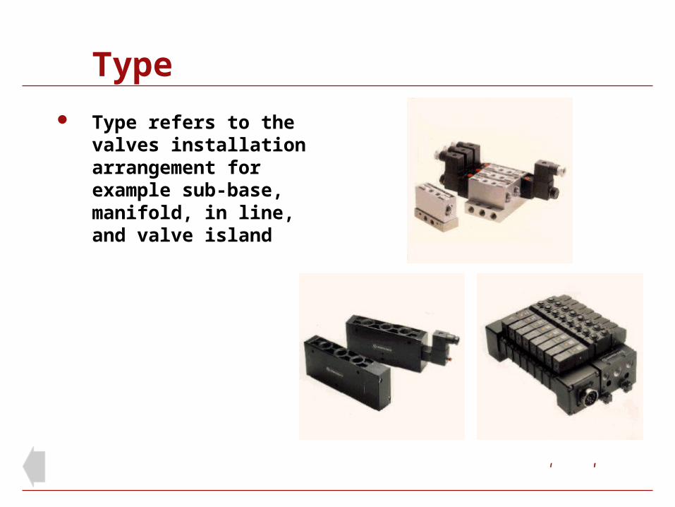
Type refers to the valves installation arrangement for example sub-base, manifold, in line, and valve island

Design
Design refers to the principle of operation around which the valve has been designed, for example, spool valve, poppet valve and plate valve
Operators
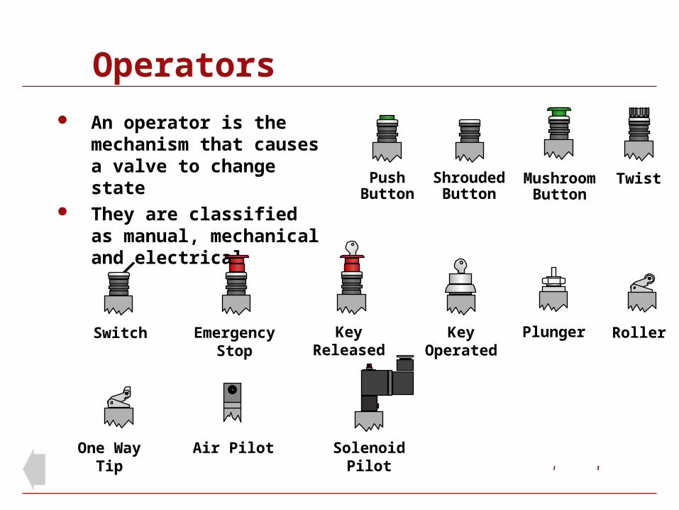
An operator is the mechanism that causes a valve to change state
They are classified as manual, mechanical and electrical
TwistPushButton
ShroudedButton
MushroomButton
KeyOperated
Switch KeyReleased
SolenoidPilot
Roller
One WayTip
Air Pilot
PlungerEmergencyStop

Actuator Control (3/2 valve)
A 3 port valve provides the inlet, outlet and exhaust path and is the normal choice for control of a single acting cylinder
In the normal position produced by the spring, the valve is closed
In the operated position produced by the push button the valve is open
The push button must be held down for as long as the cylinder is outstroked
1
2
3
12 10

Actuator Control (3/2 valve)
A 3 port valve provides the inlet, outlet and exhaust path and is the normal choice for control of a single acting cylinder
In the normal position produced by the spring, the valve is closed
In the operated position produced by the push button the valve is open
The push button must be held down for as long as the cylinder is outstroked
12 10
1
2
3

Actuator Control (5/2 valve)
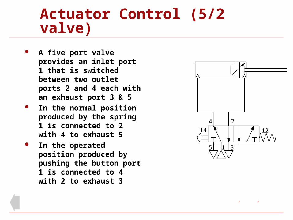
A five port valve provides an inlet port 1 that is switched between two outlet ports 2 and 4 each with an exhaust port 3 & 5
In the normal position produced by the spring 1 is connected to 2 with 4 to exhaust 5
In the operated position produced by pushing the button port 1 is connected to 4 with 2 to exhaust 3
15 3
1214
4 2
Actuator Control (5/2 valve)
A five port valve provides an inlet port 1 that is switched between two outlet ports 2 and 4 each with an exhaust port 3 & 5
In the normal position produced by the spring 1 is connected to 2 with 4 to exhaust 5
In the operated position produced by pushing the button port 1 is connected to 4 with 2 to exhaust 3
1214
15 3
4 2

Identification of the component parts of a typical 5/2 solenoid valve with spring return (Sub-base not shown)
(1) Solenoid (15mm) (2) Piston (3) Spool with disc seals (4) Valve body (5) Return spring (6) Alternative ports 2, 4 (7) Pressure indicator (8) Manual override (9) Electric connectors
34
5
6
7 8
2
1
9
Typical Valve

Poppet Valves

Poppet Valve 2/2
The Poppet valve is a simple and effective design used mainly in 2/2 and 3/2 functions
It has good sealing characteristics and can often be the choice for a supply shut off valve
A poppet seal has a butt action against a raised edged aperture
Illustrated is a 2/2 air operated poppet valve
1 2
12

Poppet Valve 3/2
Miniature 3/2 valve used for generating signals
The poppet seal will give long life (not subjected to sliding friction)
Supply to port 1 assists the spring to hold the poppet shut
Outlet port 2 is connected through the plunger to a plain exhaust port
When operated exhaust path sealed and poppet opened (flow 1 to 2)
1
2
3

Spool Valves
A long standing popular versatile design
Available in most functions 3/2, 3/3, 5/2, 5/3, etc.
Fully force balanced Wide range of styles,
sizes, operators and mounting arrangements
Suit a multiple range of applications
Spool Types
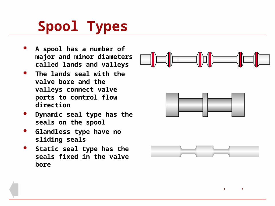
A spool has a number of major and minor diameters called lands and valleys
The lands seal with the valve bore and the valleys connect valve ports to control flow direction
Dynamic seal type has the seals on the spool
Glandless type have no sliding seals
Static seal type has the seals fixed in the valve bore

Disc Seals
A disc seal is a loose fit in the groove, with the outer diameter just in contact with the valve bore.
Under differential pressure the disc seal is pushed sideways and outwards to seal the clearance between the outer diameter of the piston and the valve bore
The slim profile gives low radial force therefore reducing friction

Spool Valve (dynamic seals)
This 5/2 valve has a spool fitted with disc seals The seals move with the spool therefore they are called
dynamic Normal position: port 1 is joined to 4 and 2 is joined to 3 Operated position: port 1 is joined to 2 and 4 is joined to 5
14 2 35
1
24
5 3
14 12
14 12

Spool Valve (dynamic seals)
This 5/2 valve has a spool fitted with disc seals The seals move with the spool therefore they are called
dynamic Normal position: port 1 is joined to 4 and 2 is joined to 3 Operated position: port 1 is joined to 2 and 4 is joined to 5
14 2 35
1
24
5 3
14 12
14 12

Spool Valve (glandless)
This 5/2 valve has a matched spool and sleeve. The fit is so precise that seals between them are unnecessary
The tiny amount of air crossing the spool lands provides an air bearing
The result is low friction and long life
14 2 3514 12
1
24
5 3
14 12

Spool Valve (glandless)
This 5/2 valve has a matched spool and sleeve. The fit is so precise that seals between them are unnecessary
The tiny amount of air crossing the spool lands provides an air bearing
The result is low friction and long life
1
24
5 3
14 12
14 2 3514 12

Spool Valve (static seals)
This 3/2 valve has a plain spool sliding within static seals The O Ring seals are held in carriers fixed in the valve
bore and positioned by spacers (not shown) The larger O Rings seal the valve bore with the carriers The smaller O Rings seal the carriers with the spool
1
2
3
1012
1
2
3
12 10
Other Valve Designs

Pressure Switch (pneumatic)
Relay to boost weak signals
Relay for a pneumatic time delay
When the signal at port 12 reaches about 50% of the supply pressure at port 1, the pressure switch operates to give a strong output signal at 2
For time delays at any pressure only the linear part of the curve will be used giving smooth adjustment
13
12 10
1
2
3
12 10
1
2
3
12 10

Pressure Switches
Pressure applied at port 1 acting on the differential annular areas holds the spool to the left
The weak or slowly rising pressure of a signal applied to port 12 needs only to reach about 50% of he pressure at port 1 to operate the valve
Port 1 is then connected to port 2
Removing the signal allows the differential force to reset the valve
1 2
3
12
1
2
3
12 10

Pressure Switches (electrical)
This fixed value example uses a built in single acting cylinder to operate a standard changeover microswitch
The operating pressure is about 3 bar this needs to overcome the combined force of the cylinder and microswitch springs
Adjustable pressure switches are also available
Fixed
Adjustable

Logic “OR” Shuttle Valve
An air signal given to either the left hand port 1 or the right hand port 1 will result in an output at port 2
The sealing disc moves across to seal the exhaust signal line to prevent loss of signal pressure
1
2
1
1
2
1
1 1
2
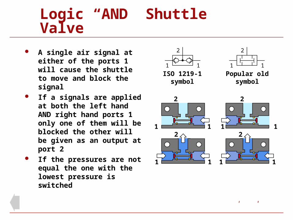
Logic “AND” Shuttle Valve
A single air signal at either of the ports 1 will cause the shuttle to move and block the signal
If a signals are applied at both the left hand AND right hand ports 1 only one of them will be blocked the other will be given as an output at port 2
If the pressures are not equal the one with the lowest pressure is switched
1 1
2
1 1
2
1 1
2
1 1
2
1 1
2
Popular oldsymbol
1 1
2
ISO 1219-1symbol

Flow Regulation
By the use of flow regulators the outstroke speed and instroke speed of a piston rod can be independently adjusted
Speed is regulated by controlling the flow of air to exhaust
The front port regulator controls the outstroke speed and the rear port regulator controls the instroke speed

Flow Regulator
Uni-directional, line mounted adjustable flow regulator
Free flow in one direction
Adjustable restricted flow in the other direction

Flow Regulator
Uni-directional, line mounted adjustable flow regulator
Free flow in one direction
Adjustable restricted flow in the other direction

Banjo Flow Regulator
Designed to fit directly in to cylinder ports, so placing adjustment at the appropriate cylinder end
Two types: One to give conventional
flow restriction out of the cylinder and free flow in (as illustrated)
The other type to give restricted flow in to the cylinder and free flow out (not illustrated)

Quick Exhaust Valve
In some applications cylinder speed can be increased by 50% when using a quick exhaust valve
When operated, air from the front of the cylinder exhausts directly through the quick exhaust valve
The faster exhaust gives a lower back pressure in the cylinder therefore a higher pressure differential to drive out the piston rod
Quick Exhaust Valve
1
2
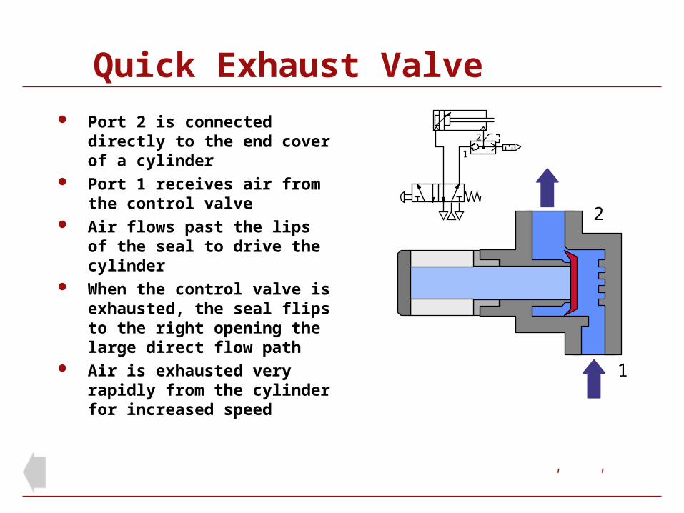
Port 2 is connected directly to the end cover of a cylinder
Port 1 receives air from the control valve
Air flows past the lips of the seal to drive the cylinder
When the control valve is exhausted, the seal flips to the right opening the large direct flow path
Air is exhausted very rapidly from the cylinder for increased speed
1
2
Quick Exhaust Valve
1
2
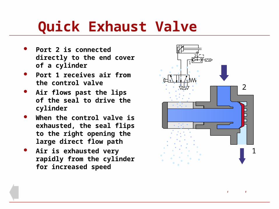
Port 2 is connected directly to the end cover of a cylinder
Port 1 receives air from the control valve
Air flows past the lips of the seal to drive the cylinder
When the control valve is exhausted, the seal flips to the right opening the large direct flow path
Air is exhausted very rapidly from the cylinder for increased speed
1
2
Solenoid Valves
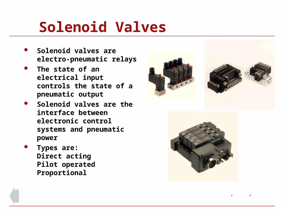
Solenoid valves are electro-pneumatic relays
The state of an electrical input controls the state of a pneumatic output
Solenoid valves are the interface between electronic control systems and pneumatic power
Types are:Direct actingPilot operatedProportional

Direct Acting Solenoid Valves
Used for:Signal generation and processing Control of small bore single acting cylinders
Single station sub-base mounted
Multi-station sub-base mounted
Integrated to larger valves to become solenoid pilot operated valves
15, 22, 32 represent the mm width of the valve
Nugget 30
Excel 15
Excel 22
Excel 32
Principle of operation
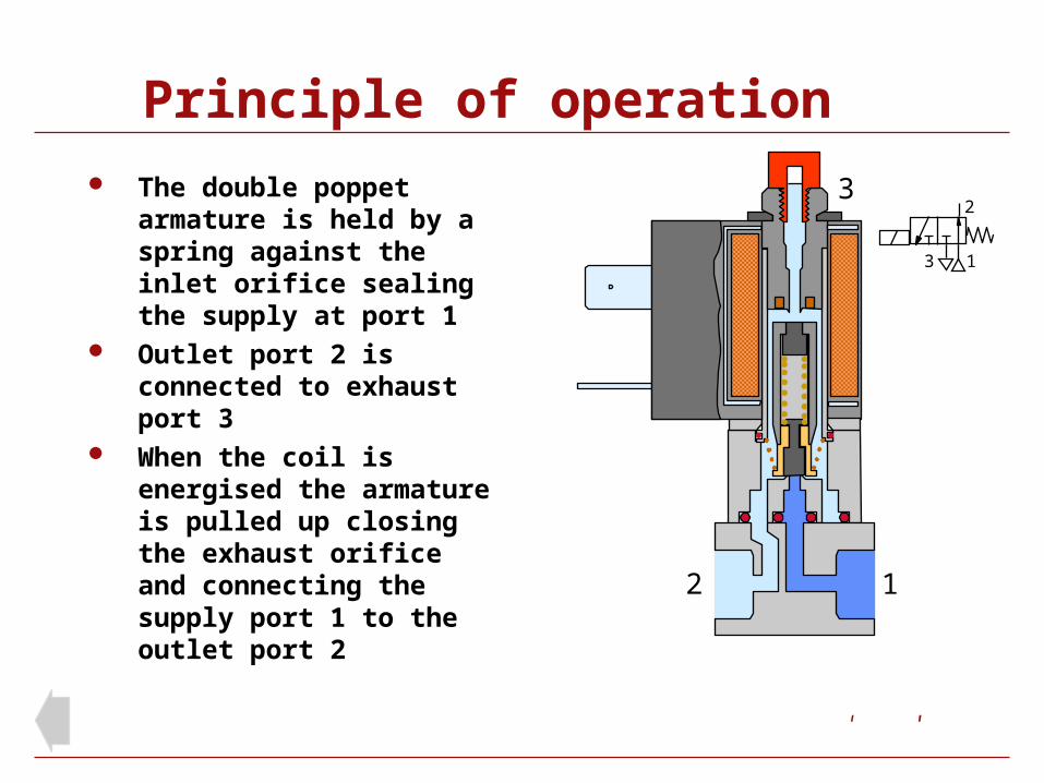
The double poppet armature is held by a spring against the inlet orifice sealing the supply at port 1
Outlet port 2 is connected to exhaust port 3
When the coil is energised the armature is pulled up closing the exhaust orifice and connecting the supply port 1 to the outlet port 2
12
3
1
2
3

Principle of operation
The double poppet armature is held by a spring against the inlet orifice sealing the supply at port 1
Outlet port 2 is connected to exhaust port 3
When the coil is energised the armature is pulled up closing the exhaust orifice and connecting the supply port 1 to the outlet port 2
1
1
2
3
2
3

End