Embed Size (px)
Citation preview
Use and Maintenance Manual
Rev. 01.14 Pneumatic Roller Vibrators 1/16
Pneumatic Roller Vibrators
VVR Family
Use and Maintenance Manual
Use and Maintenance Manual
Rev. 01.14 Pneumatic Roller Vibrators 2/16
Index
1 Introduction .......................................................... 3
1.1 Aim of the publication .......................................... 3 1.2 Publication identification ..................................... 3 1.3 Liability ................................................................. 3 1.4 Copyright .............................................................. 3 1.5 Use of the manual ................................................ 3 1.6 Maintenance of the manual ................................. 3 1.7 Updates ................................................................ 3 1.8 Warning symbols .................................................. 3 1.9 Normative references ........................................... 4
2 Safe use ................................................................. 4
2.1 Intended use ........................................................ 4 2.2 Usage not permitted............................................. 4 2.3 Potential dangers of a general nature .................. 4 2.4 Vibrator symbols .................................................. 4 2.5 Risks relating to vibrations ................................... 5 2.6 Risks relating to noise ........................................... 5 2.7 Operator qualifications ......................................... 6 2.8 Methods of personal protection .......................... 6
3 General description of the vibrator ..................... 7
3.1 Introduction ......................................................... 7 3.2 Identification of models ....................................... 7 3.3 Identification of the equipment ........................... 7 3.4 Fundamental components of the vibrator ........... 7
3.4.1 Vibrating body ................................................ 7 3.4.2 Rings ................................................................ 8 3.4.3 Roller ............................................................... 8 3.4.4 Front cover ...................................................... 8 3.4.5 Rear cover ........................................................ 8
4 Technical data ....................................................... 8
4.1 Main sizes and weights ......................................... 8 4.2 Technical data ....................................................... 8 4.3 Construction criteria............................................. 8 4.4 Environmental criteria .......................................... 8
5 Transport, packaging and storage ....................... 8
5.1 Transport .............................................................. 8 5.2 Packaging.............................................................. 8 5.3 Storage ................................................................. 9
6 Installation ............................................................ 9
6.1 Environmental conditions required for use .......... 9 6.2 Removal of protective materials .......................... 9 6.3 Positioning the vibrator ........................................ 9 6.4 Securing the Vibrator ........................................... 9 6.5 Connection to energy sources ............................ 11 6.6 Quality of the air supply ..................................... 12
7 Use ....................................................................... 13
7.1 Preliminary checks ............................................. 13 7.2 First ignition ....................................................... 13 7.3 Functionality checks ........................................... 13 7.4 Checks after the first hour .................................. 13 7.5 Function anomalies ............................................ 13
8 Ordinary maintenance ....................................... 13
8.1 Maintenance procedures ................................... 13 8.1.1 Visual inspection .......................................... 14 8.1.2 Cleaning ......................................................... 14 8.1.3 Periodic checks .............................................. 14
9 Disposal ............................................................... 14
10 Technical Assistance .......................................... 14
11 Guarantee ............................................................ 14
11.1 Guarantee conditions .........................................14
Use and Maintenance Manual
Rev. 01.14 Pneumatic Roller Vibrators 3/16
1 Introduction
1.1 Aim of the publication
This manual is aimed at those who use pneumatic roller
vibrators belonging to the VVR family; it contains all the
necessary information for the correct use of these vibrators.
The proper functioning and lifespan of each vibrator relies on
scrupulous and careful respect for the instructions and rules
contained in the manual, as well as the safety and protection
of the operator and materials processed. It is therefore
advised that you carefully read and meticulously follow all the
guidelines contained in this publication. All information is
updated at the date of publication.
1.2 Publication identification
The “USE AND MAINTENANCE MANUAL” is an official
document produced by VIBRONORD and constitutes an
integral part of provision; it is distinguished by a Document
Code, located at the foot of the page, which enables
identification, traceability and successive references.
1.3 Liability
VIBRONORD has made every effort to ensure that the
information contained in this manual is accurate and
exhaustive, however no responsibility is assumed in the case
of error or inaccuracy. VIBRONORD retains the right to
modify, at any time and without warning, the specification of
the hardware herein described. VIBRONORD reserves the
right to modify this manual at any time and without the
obligation of forewarning.
1.4 Copyright
The reproduction, transmission, transcription or recording in
a search engine of this information, as a whole or in part, as
well as translation into other languages, in whatever format,
of this manual and connected documents, is completely
forbidden without prior written authorisation from
VIBRONORD.
1.5 Use of the manual
The manual is subdivided into 11 chapters, as specified in the
index.
The manual should be read sequentially, from beginning to
end, one page after another and the various warnings and
notifications must be understood and remembered.
As it is assumed that the operator is qualified in the use of
this type of equipment, all general information and
instructions have been omitted as these should necessarily
enter into his/her field of experience.
The manual should be considered an integral part of the
vibrator and should therefore be included with it whenever it
is relocated, whether this be internally or externally to the
company where it is used.
1.6 Maintenance of the manual
The manual should be cared for throughout the life of the
vibrator. Keep the manual in a place protected from heat and
humidity. Do not remove, tear or rewrite any part of this
manual for any reason.
In case of operational situations not mentioned or fifferent of
those given in the manual, please contact the manufacturer
for a possible update.
The manual must be kept with the greatest care; it is
necessary to avoid its inadequate safe-keeping and even
partial damage to its contents.
The operator is responsible for the immediate replacement of
the manual in the event that it is damaged, lost, or becomes
totally or partially illegible.
1.7 Updates
VIBRONORD reserves the right to update this manual at any
time and without the obligation of forewarning.
1.8 Warning symbols
Within this manual the following symbols indicate to the user
particularly relevant information and especially delicate or
dangerous procedures.
���� NOTE Indicates important information
;;;; WARNING
Indicates a situation in which poor attention or incorrectly
followed procedures could cause damage (possibly
irreparable) to the vibrator.
!!!! ATTENTION This is used to indicate a situation which puts people in
danger.
In addition to these general symbols, particular symbols are
associated with some specific risks; these are from time to
time explained throughout the text.
These particular symbols that sygnal risky areas and conduct
are reported on the vibrator by means of adhesive plates.
Before approaching the vibrator and putting it to use, it is
necessary to carefully note the symbols listed above, their
messages and instructions and to understand their import.
The operator is responsible for the immediate replacement of
the adhesive plates applied to the vibrator in the case of loss
or damage or if they have become partially or totally illegible.
Use and Maintenance Manual
Rev. 01.14 Pneumatic Roller Vibrators 4/16
1.9 Normative references
The contents of this publication are provided in conformance
with the following regulations:
EN ISO 12100
and with regards to European Directive
MD 2006/42/CE (Machinery Directive)
2 Safe use
2.1 Intended use
!!!! ATTENTION The use of the vibrator and its accessories for any activity
different from that allowed and specified in this manual is
absolutely forbidden.
VVR pneumatic vibrators are typically used in conjunction
with mechanical equipment for carrying material. VVR
pneumatic vibrators can be installed in any position and their
primary aim is to cause the vibration of the structure to which
they are fastened, in order to facilitate the movement of the
material carried.
VVR pneumatic vibrators applied to formwork allow material
to be compacted.
2.2 Usage not permitted
!!!! ATTENTION All uses not explicitly indicated in the preceding paragraph
should be considered not permitted, without the specific
approval of VIBRONORD.
!!!! ATTENTION The pneumatic vibrators described in this manual cannot be
installed and used in potentially explosive areas (ATEX).
2.3 Potential dangers of a general nature
!!!! ATTENTION The majority of accidents at work result from a failure to
observe the most basic safety regulations. It is necessary
that whoever operates the vibrator is perfectly aware of and
respects the regulations written in this publication and on
the warning plates.
Adherence to the general regulations indicated below is
strictly necessary.
!!!! ATTENTION Before using the vibrator, carefully read this manual and
check that the installation has been carried out correctly,
according to the instructions given in the following pages.
Also carefully note the adhesives affixed to the vibrator.
!!!! ATTENTION Any action performed on the vibrator must occur with the
complete absence of pressure. Failure to follow this
instruction can put the safety of the installer in danger.
!!!! ATTENTION The inhibition or dismantling of the covers mounted on the
vibrator is absolutely forbidden for any reason.
!!!! ATTENTION Before proceeding to use the vibrator ensure that no
components are visibly damaged.
!!!! ATTENTION Do not carry out any work or modifications of any kind on
the vibrator. Do not modify in any way and for any reason
components of the vibrator, with the aim to adapt other
devices on it. In the event of malfunction/accident resulting
from a failure to follow the instructions above, VIBRONORD
will not respond to the consequences induced.
Please contact VIBRONORD beforehand in the event that
changes to be made to the vibrator are required.
!!!! ATTENTION Check that the structure to be vibrated is elastically isolated
and that there are no pieces or materials left free which
could, as a result of the vibration, fall and cause damage to
the operator or others.
!!!! ATTENTION In the course of cleaning the vibrator or its components
never use solvents of any kind or acidic substances which
could corrode the metal surfaces.
2.4 Vibrator symbols
All warnings and given principles for the safe use of the
product are present on the body of the vibrator by means of
adhesive plates or direct engraving onto the body of the
vibrator.
Use and Maintenance Manual
Rev. 01.14 Pneumatic Roller Vibrators 5/16
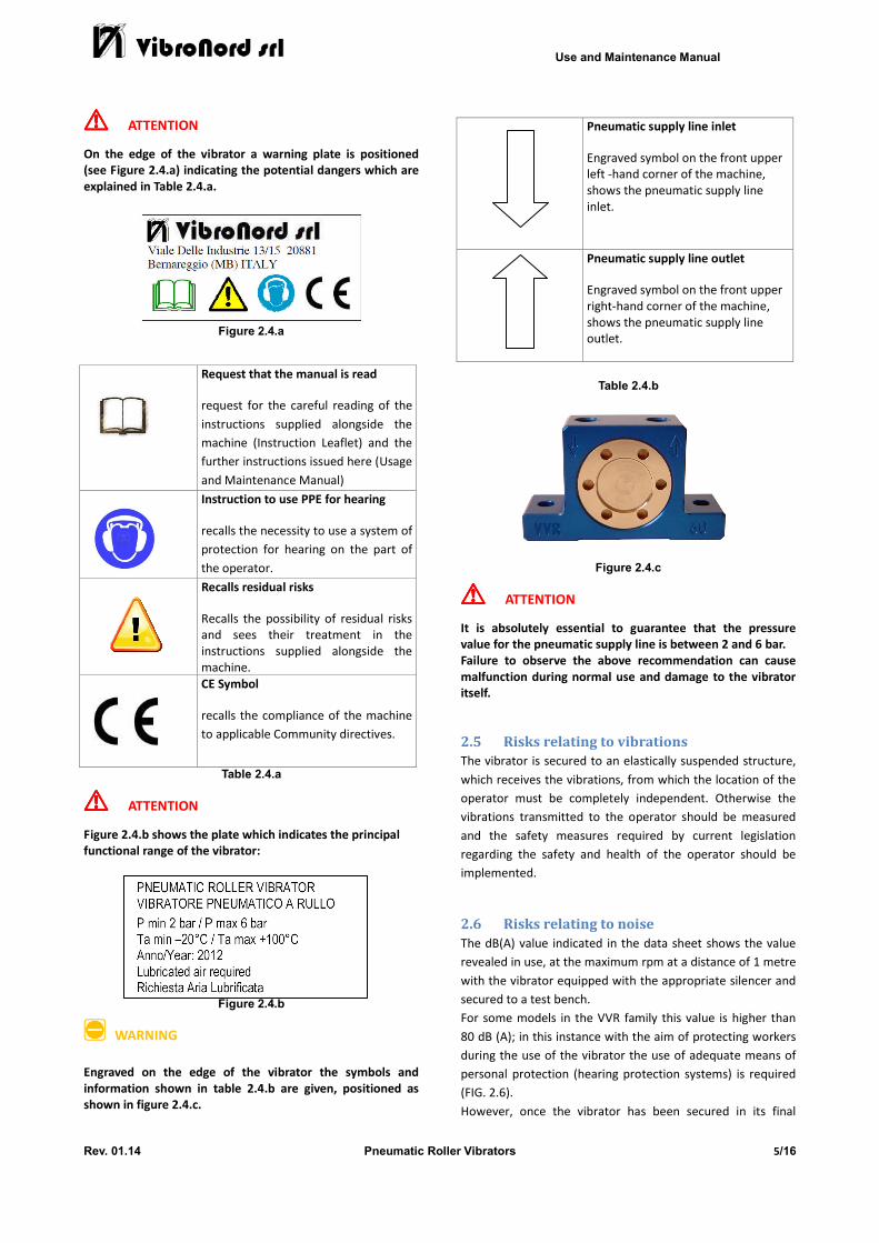
!!!! ATTENTION On the edge of the vibrator a warning plate is positioned
(see Figure 2.4.a) indicating the potential dangers which are
explained in Table 2.4.a.
Figure 2.4.a
Request that the manual is read
request for the careful reading of the
instructions supplied alongside the
machine (Instruction Leaflet) and the
further instructions issued here (Usage
and Maintenance Manual)
Instruction to use PPE for hearing
recalls the necessity to use a system of
protection for hearing on the part of
the operator.
Recalls residual risks
Recalls the possibility of residual risks
and sees their treatment in the
instructions supplied alongside the
machine.
CE Symbol
recalls the compliance of the machine
to applicable Community directives.
Table 2.4.a
!!!! ATTENTION Figure 2.4.b shows the plate which indicates the principal
functional range of the vibrator:
Figure 2.4.b
;;;; WARNING Engraved on the edge of the vibrator the symbols and
information shown in table 2.4.b are given, positioned as
shown in figure 2.4.c.
Pneumatic supply line inlet
Engraved symbol on the front upper
left -hand corner of the machine,
shows the pneumatic supply line
inlet.
Pneumatic supply line outlet
Engraved symbol on the front upper
right-hand corner of the machine,
shows the pneumatic supply line
outlet.
Table 2.4.b
Figure 2.4.c
!!!! ATTENTION It is absolutely essential to guarantee that the pressure
value for the pneumatic supply line is between 2 and 6 bar.
Failure to observe the above recommendation can cause
malfunction during normal use and damage to the vibrator
itself.
2.5 Risks relating to vibrations
The vibrator is secured to an elastically suspended structure,
which receives the vibrations, from which the location of the
operator must be completely independent. Otherwise the
vibrations transmitted to the operator should be measured
and the safety measures required by current legislation
regarding the safety and health of the operator should be
implemented.
2.6 Risks relating to noise
The dB(A) value indicated in the data sheet shows the value
revealed in use, at the maximum rpm at a distance of 1 metre
with the vibrator equipped with the appropriate silencer and
secured to a test bench.
For some models in the VVR family this value is higher than
80 dB (A); in this instance with the aim of protecting workers
during the use of the vibrator the use of adequate means of
personal protection (hearing protection systems) is required
(FIG. 2.6).
However, once the vibrator has been secured in its final
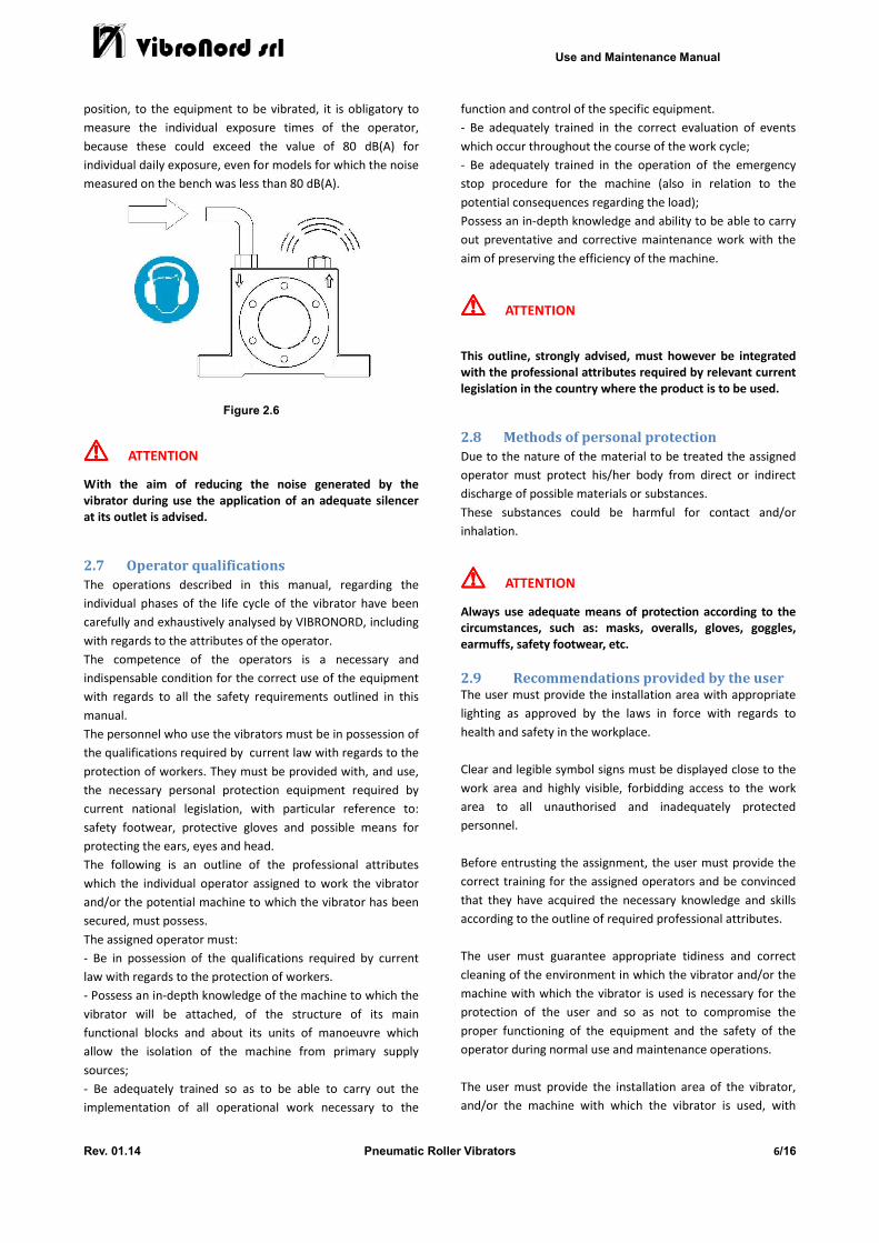
Use and Maintenance Manual
Rev. 01.14 Pneumatic Roller Vibrators 6/16
position, to the equipment to be vibrated, it is obligatory to
measure the individual exposure times of the operator,
because these could exceed the value of 80 dB(A) for
individual daily exposure, even for models for which the noise
measured on the bench was less than 80 dB(A).
Figure 2.6
!!!! ATTENTION With the aim of reducing the noise generated by the
vibrator during use the application of an adequate silencer
at its outlet is advised.
2.7 Operator qualifications
The operations described in this manual, regarding the
individual phases of the life cycle of the vibrator have been
carefully and exhaustively analysed by VIBRONORD, including
with regards to the attributes of the operator.
The competence of the operators is a necessary and
indispensable condition for the correct use of the equipment
with regards to all the safety requirements outlined in this
manual.
The personnel who use the vibrators must be in possession of
the qualifications required by current law with regards to the
protection of workers. They must be provided with, and use,
the necessary personal protection equipment required by
current national legislation, with particular reference to:
safety footwear, protective gloves and possible means for
protecting the ears, eyes and head.
The following is an outline of the professional attributes
which the individual operator assigned to work the vibrator
and/or the potential machine to which the vibrator has been
secured, must possess.
The assigned operator must:
- Be in possession of the qualifications required by current
law with regards to the protection of workers.
- Possess an in-depth knowledge of the machine to which the
vibrator will be attached, of the structure of its main
functional blocks and about its units of manoeuvre which
allow the isolation of the machine from primary supply
sources;
- Be adequately trained so as to be able to carry out the
implementation of all operational work necessary to the
function and control of the specific equipment.
- Be adequately trained in the correct evaluation of events
which occur throughout the course of the work cycle;
- Be adequately trained in the operation of the emergency
stop procedure for the machine (also in relation to the
potential consequences regarding the load);
Possess an in-depth knowledge and ability to be able to carry
out preventative and corrective maintenance work with the
aim of preserving the efficiency of the machine.
!!!! ATTENTION This outline, strongly advised, must however be integrated
with the professional attributes required by relevant current
legislation in the country where the product is to be used.
2.8 Methods of personal protection
Due to the nature of the material to be treated the assigned
operator must protect his/her body from direct or indirect
discharge of possible materials or substances.
These substances could be harmful for contact and/or
inhalation.
!!!! ATTENTION Always use adequate means of protection according to the
circumstances, such as: masks, overalls, gloves, goggles,
earmuffs, safety footwear, etc.
2.9 Recommendations provided by the user The user must provide the installation area with appropriate
lighting as approved by the laws in force with regards to
health and safety in the workplace.
Clear and legible symbol signs must be displayed close to the
work area and highly visible, forbidding access to the work
area to all unauthorised and inadequately protected
personnel.
Before entrusting the assignment, the user must provide the
correct training for the assigned operators and be convinced
that they have acquired the necessary knowledge and skills
according to the outline of required professional attributes.
The user must guarantee appropriate tidiness and correct
cleaning of the environment in which the vibrator and/or the
machine with which the vibrator is used is necessary for the
protection of the user and so as not to compromise the
proper functioning of the equipment and the safety of the
operator during normal use and maintenance operations.
The user must provide the installation area of the vibrator,
and/or the machine with which the vibrator is used, with
Use and Maintenance Manual
Rev. 01.14 Pneumatic Roller Vibrators 7/16
adequate fire-fighting stations. The operator must be able to
access, in case of an emergency, the general device for
intercepting the main supply.
3 General description of the vibrator
3.1 Introduction
Pneumatic vibrators in the VVR family are machines intended
to create a vibration.
They consist of a central body, made from aluminium and
provided with adequate holes for securing the vibrator to the
structure to be vibrated, outer covers and elements which
generate the vibration (roller) which, rotating at the rpm
determined by the pressure of the pneumatic supply line,
generate a centrifugal rotating force which causes the
vibrations.
These vibrations are used to shake up various pieces or
materials; therefore in industry and construction to compact,
filter, sift and transport materials.
3.2 Identification of models
The VVR family of vibrators is composed of 4 models
identified by an alphanumeric code structured as follows
(TAB. 3.2):
Table 3.2
The various models differ in their dimensions, rpm, force
generated and other technical characteristics (See Chapter 4).
3.3 Identification of the equipment
All vibrators in the VVR family are identified by the incision of
the acronym VVR and their model number, located on the
front part of the main body
Identification of the family group
Words are engraved on the front
lower left-hand corner.
Identification of the vibrator
model
Words are engraved on the front
lower right-hand corner
Otherwise appropriate nameplates are affixed to the body of the vibrator (See Para. 2.4)
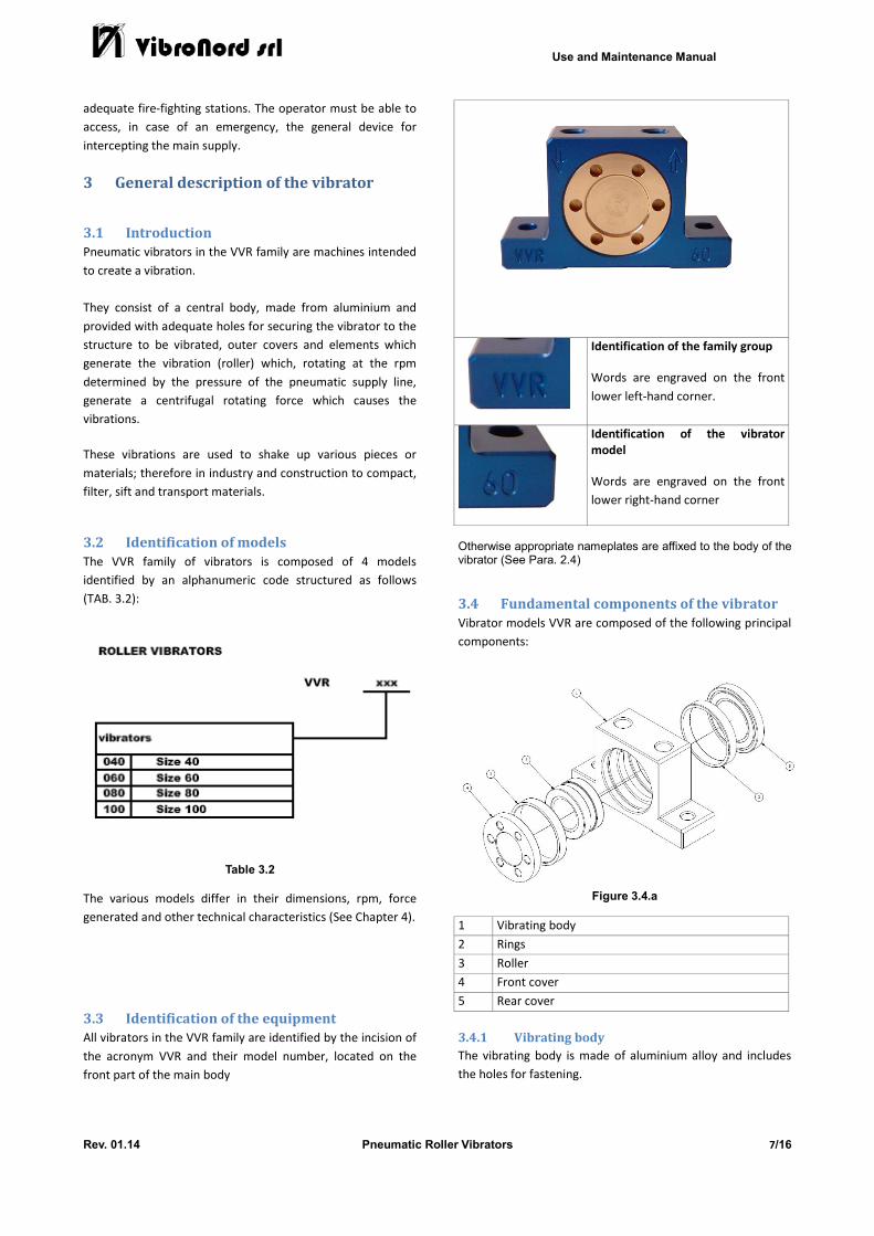
3.4 Fundamental components of the vibrator
Vibrator models VVR are composed of the following principal
components:
Figure 3.4.a
1 Vibrating body
2 Rings
3 Roller
4 Front cover
5 Rear cover
3.4.1 Vibrating body
The vibrating body is made of aluminium alloy and includes
the holes for fastening.
Use and Maintenance Manual
Rev. 01.14 Pneumatic Roller Vibrators 8/16
3.4.2 Rings
The rings are made of steel and constitute the guide for
rolling the sphere.
3.4.3 Roller
The roller constitutes the element which generates the
vibrations
3.4.4 Front cover
The front cover is made of bronze and is supplied with a
thread for fastening it to the body of the vibrator.
3.4.5 Rear cover
The rear cover is made of bronze and is supplied with a left-
hand thread for fastening it to the body of the vibrator.
4 Technical data
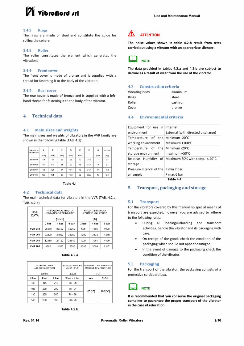
4.1 Main sizes and weights
The main sizes and weights of vibrators in the VVR family are
shown in the following table (TAB. 4.1):
Table 4.1
4.2 Technical data
The main technical data for vibrators in the VVR (TAB. 4.2.a,
TAB. 4.2.b)
Table 4.2.a
Table 4.2.b
!!!! ATTENTION The noise values shown in table 4.2.b result from tests
carried out using a vibrator with an appropriate silencer.
���� NOTE The data provided in tables 4.2.a and 4.2.b are subject to
decline as a result of wear from the use of the vibrator.
4.3 Construction criteria
Vibrating body aluminium
Rings steel
Roller cast iron
Cover bronze
4.4 Environmental criteria
Equipment for use in
environment
Internal
External (with directed discharge)
Temperature of the
working environment
Minimum -20°C
Maximum +100°C
Temperature of the
storage environment
Minimum -20°C
maximum +50°C
Relative Humidity of
storage
Maximum 80% with temp. ≤ 40°C.
Pressure interval of the
air supply
P min 2 bar
P max 6 bar
Table 4.4
5 Transport, packaging and storage
5.1 Transport
For the vibrators covered by this manual no special means of
transport are expected, however you are advised to adhere
to the following rules:
• During all loading/unloading and transport
activities, handle the vibrator and its packaging with
care.
• On receipt of the goods check the condition of the
packaging which should not appear damaged.
• In the event of damage to the packaging check the
condition of the vibrator.
5.2 Packaging
For the transport of the vibrator, the packaging consists of a
protective cardboard box.
���� NOTE It is recommended that you conserve the original packaging
container to guarantee the proper transport of the vibrator
in the case of relocation.
Use and Maintenance Manual
Rev. 01.14 Pneumatic Roller Vibrators 9/16
5.3 Storage
The vibrator must be stored in an enclosed, dry place in
which the temperature is between -20°C and +50°C and
the relative humidity does not exceed 80%. Avoid humid and
brackish storage areas.
;;;; WARNING Whenever an extended storage period has been necessary it
is recommended that you carry out a thorough check of the
vibrator before putting it to use.
!!!! ATTENTION However the vibrator is to be stored after use it is
recommended that it is allowed to cool completely, before
being thoroughly cleaned before storage.
6 Installation
6.1 Environmental conditions required for use
The installation environment must be well-ventilated and
adequately lit.
The environmental conditions must respect the criteria given
in 4.4
6.2 Removal of protective materials
The vibrator is shipped in special containers (packaging)
which protect it from external agents during transport and for
periods of storage. The removal of packaging material must
be carried out with extreme care so as to avoid, during this
activity, handling the structures and surfaces of the vibrator
inappropriately.
6.3 Positioning the vibrator
The correct positioning of the vibrator guarantees the perfect
functioning of the system.
Position the vibrator away from contact with corrosive
liquids.
When positioning the vibrator, consider that the space
available around the vibrator must be calculated so as to
guarantee proper ventilation and allow the operator to
perform the following activities:
• Carry out all movement necessary for mounting and
dismounting activities including the use of potential
accessories provided;
• Perform ordinary maintenance activities, especially
those of cleaning;
After having secured the vibrator it is recommended that you
check that it is perfectly mounted and fastened.
!!!! ATTENTION In the act of installation completely and absolutely AVOID
the establishment of structural ties with surfaces or
structures subject to stress or dynamic loads external to the
vibrator.
When in the area where the vibrator has to be installed, a
connection with structures subject to loads is foreseen,
explain the relative difficulties to VIBRONORD before the
purchase.
6.4 Securing the Vibrator
The body of the pneumatic vibrators in the VVR family is
furnished with two ready-made holes to facilitate its
fastening to the structure/equipment to be vibrated.
The area to which the vibrator has to be secured must be
mechanically robust enough to be able to endure the
vibrations generated and allow an adequate mechanical
coupling, with the aim of better distributing the force
generated by the vibrator. To guarantee the correct
mechanical fixture recourse to the use of a coupling bracket
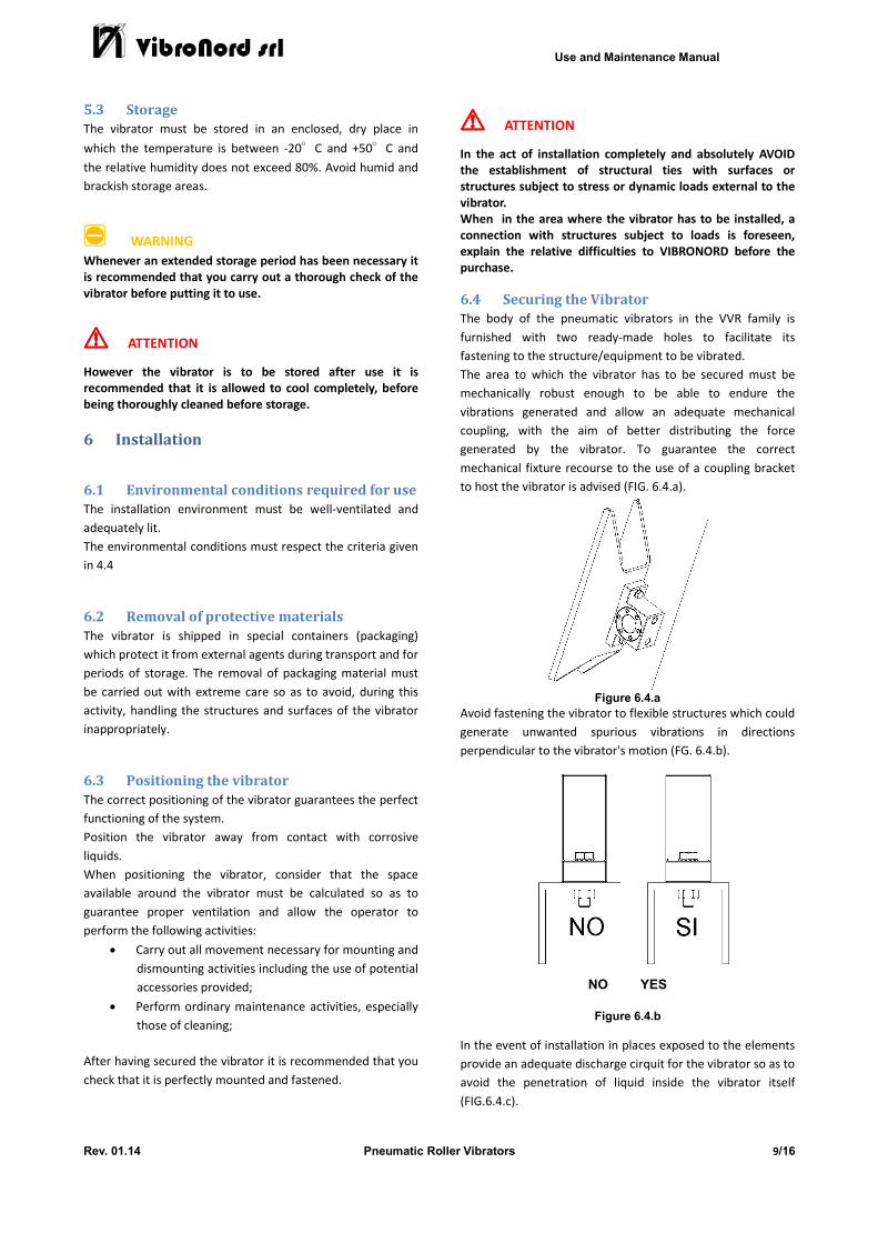
to host the vibrator is advised (FIG. 6.4.a).
Figure 6.4.a
Avoid fastening the vibrator to flexible structures which could
generate unwanted spurious vibrations in directions
perpendicular to the vibrator's motion (FG. 6.4.b).
NO YES
Figure 6.4.b
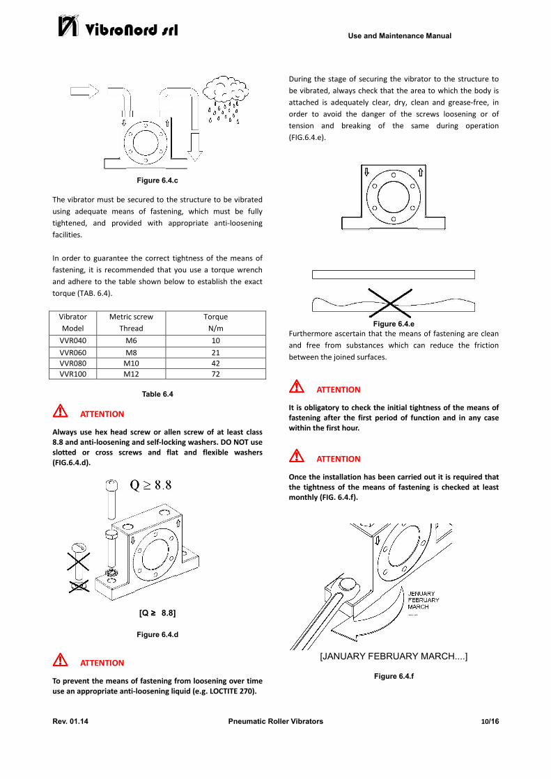
In the event of installation in places exposed to the elements
provide an adequate discharge cirquit for the vibrator so as to
avoid the penetration of liquid inside the vibrator itself
(FIG.6.4.c).
Use and Maintenance Manual
Rev. 01.14 Pneumatic Roller Vibrators 10/16
Figure 6.4.c
The vibrator must be secured to the structure to be vibrated
using adequate means of fastening, which must be fully
tightened, and provided with appropriate anti-loosening
facilities.
In order to guarantee the correct tightness of the means of
fastening, it is recommended that you use a torque wrench
and adhere to the table shown below to establish the exact
torque (TAB. 6.4).
Vibrator
Model
Metric screw
Thread
Torque
N/m
VVR040 M6 10
VVR060 M8 21
VVR080 M10 42
VVR100 M12 72
Table 6.4
!!!! ATTENTION Always use hex head screw or allen screw of at least class
8.8 and anti-loosening and self-locking washers. DO NOT use
slotted or cross screws and flat and flexible washers
(FIG.6.4.d).
[Q ≥≥≥≥ 8.8]
Figure 6.4.d
!!!! ATTENTION To prevent the means of fastening from loosening over time
use an appropriate anti-loosening liquid (e.g. LOCTITE 270).
During the stage of securing the vibrator to the structure to
be vibrated, always check that the area to which the body is
attached is adequately clear, dry, clean and grease-free, in
order to avoid the danger of the screws loosening or of
tension and breaking of the same during operation
(FIG.6.4.e).
Figure 6.4.e
Furthermore ascertain that the means of fastening are clean
and free from substances which can reduce the friction
between the joined surfaces.
!!!! ATTENTION It is obligatory to check the initial tightness of the means of
fastening after the first period of function and in any case
within the first hour.
!!!! ATTENTION Once the installation has been carried out it is required that
the tightness of the means of fastening is checked at least
monthly (FIG. 6.4.f).
[JANUARY FEBRUARY MARCH....]
Figure 6.4.f
Use and Maintenance Manual
Rev. 01.14 Pneumatic Roller Vibrators 11/16
!!!! ATTENTION In the occasion that the vibrator is mounted in a suspended
position, from which its potential fall could put people in
danger, it is appropriate to provide facilities which have the
potential to prevent, or protect from, a fall; these should be
prepared by the installer.
!!!! ATTENTION The vibrator is subject to mechanical stress during its normal
function due to its own vibrating action. In order to
guarantee its correct and safe function the following is
recommended:
• Regularly check the integrity of the fastening
components and in the case that they are
damaged or worn, carry out an immediate
substitution.
• Regularly verify the tightness of the fastening
components.
• Substitute the fastening components at least every
500 working hours to prevent them from fatigue
failures.
VIBRONORD takes no responsibility for accidents or
malfunction resulting from failure to check the means of
securing the vibrator.
6.5 Connection to energy sources
Connection to energy sources must be carried out with full
respect for the specifications made in this chapter.
!!!! ATTENTION Connection to the pneumatic line must be carried out by
fully qualified personnel with regards to all safety
qualifications required by current legislation with reference
to the place where the vibrator is installed. All connections
must be made with the absence of pressure.
Pneumatic vibrators in the VVS family are equipped for the
mounting of two fittings dedicated to the connection of the
pipe for the supply and discharge of air.
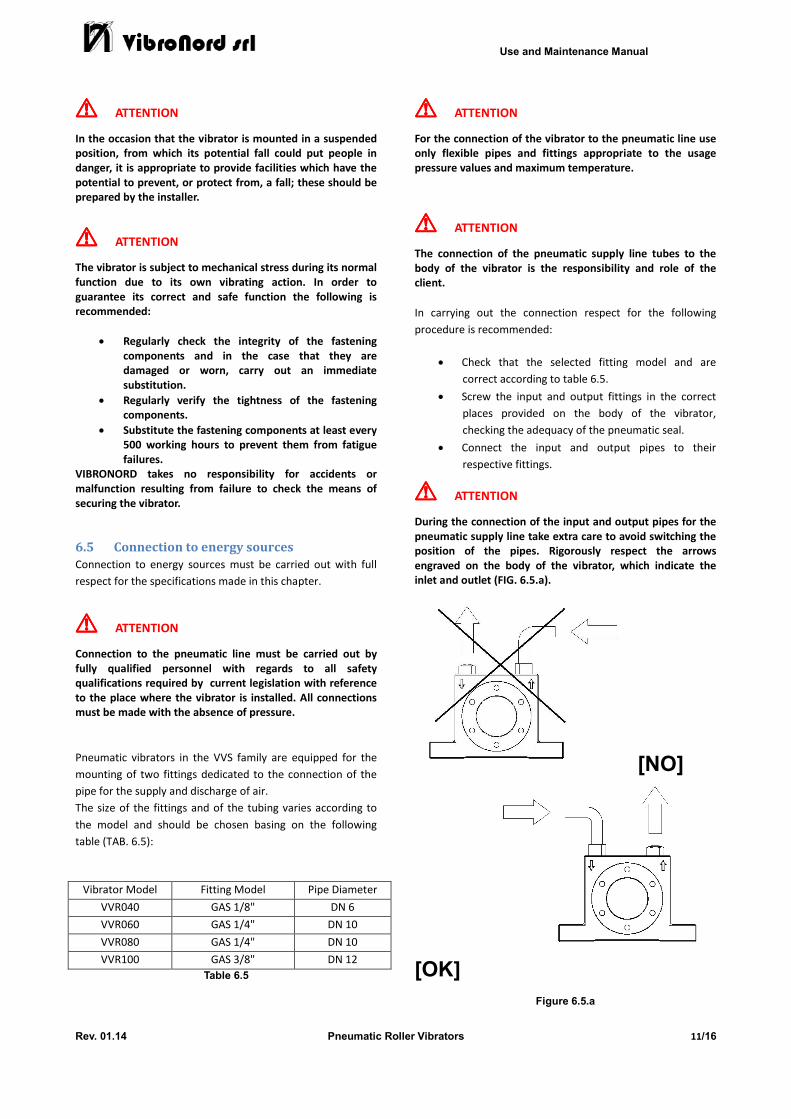
The size of the fittings and of the tubing varies according to
the model and should be chosen basing on the following
table (TAB. 6.5):
Vibrator Model Fitting Model Pipe Diameter
VVR040 GAS 1/8" DN 6
VVR060 GAS 1/4" DN 10
VVR080 GAS 1/4" DN 10
VVR100 GAS 3/8" DN 12
Table 6.5
!!!! ATTENTION For the connection of the vibrator to the pneumatic line use
only flexible pipes and fittings appropriate to the usage
pressure values and maximum temperature.
!!!! ATTENTION The connection of the pneumatic supply line tubes to the
body of the vibrator is the responsibility and role of the
client.
In carrying out the connection respect for the following
procedure is recommended:
• Check that the selected fitting model and are
correct according to table 6.5.
• Screw the input and output fittings in the correct
places provided on the body of the vibrator,
checking the adequacy of the pneumatic seal.
• Connect the input and output pipes to their
respective fittings.
!!!! ATTENTION During the connection of the input and output pipes for the
pneumatic supply line take extra care to avoid switching the
position of the pipes. Rigorously respect the arrows
engraved on the body of the vibrator, which indicate the
inlet and outlet (FIG. 6.5.a).
[NO]
[OK]
Figure 6.5.a
Use and Maintenance Manual
Rev. 01.14 Pneumatic Roller Vibrators 12/16
!!!! ATTENTION After having connected the vibrator to the pneumatic supply
line it is recommended that you fix the input and output
pipes nearby the vibrator itself in order to avoid, in case of
accidental detachment, the risk of bruising resulting from a
whip effect.
!!!! ATTENTION The connection of the vibrator to the pneumatic line
requires the installation of an interception valve placed on
the inlet pipe.
This valve allows for the supply line to be cut off and
safeguards the operator in all cases when it is necessary to
work on the vibrator; ordinary maintenance and/or
replacement work.
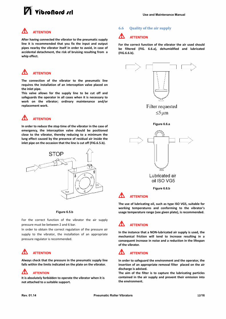
!!!! ATTENTION In order to reduce the stop time of the vibrator in the case of
emergency, the interception valve should be positioned
close to the vibrator, thereby reducing to a minimum the
lung effect caused by the presence of residual air inside the
inlet pipe on the occasion that the line is cut off (FIG.6.5.b).
Figure 6.5.b
For the correct function of the vibrator the air supply
pressure must be between 2 and 6 bar.
In order to obtain the correct regulation of the pressure air
supply to the vibrator, the installation of an appropriate
pressure regulator is recommended.
!!!! ATTENTION Always check that the pressure in the pneumatic supply line
falls within the limits indicated on the plate on the vibrator.
!!!! ATTENTION
It is absolutely forbidden to operate the vibrator when it is
not attached to a suitable support.
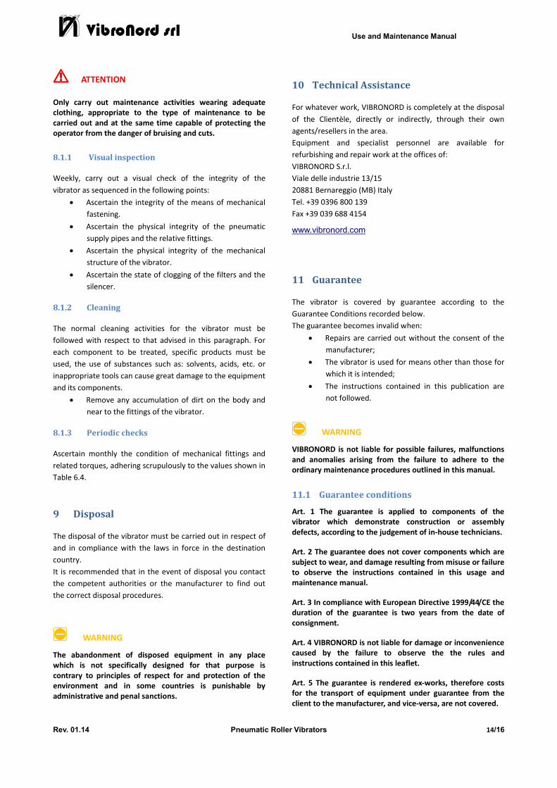
6.6 Quality of the air supply
!!!! ATTENTION For the correct function of the vibrator the air used should
be filtered (FIG. 6.6.a), dehumidified and lubricated
(FIG.6.6.b).
Figure 6.6.a
Figure 6.6.b
!!!! ATTENTION The use of lubricating oil, such as type ISO VG5, suitable for
working temperatures and conforming to the vibrator's
usage temperature range (see given plate), is recommended.
!!!! ATTENTION In the instance that a NON-lubricated air supply is used, the
mechanical friction will tend to increase resulting in a
consequent increase in noise and a reduction in the lifespan
of the vibrator.
!!!! ATTENTION In order to safeguard the environment and the operator, the
insertion of an appropriate removal filter placed on the air
discharge is advised.
The aim of the filter is to capture the lubricating particles
contained in the air supply and prevent their emission into
the environment.

Use and Maintenance Manual
Rev. 01.14 Pneumatic Roller Vibrators 13/16
7 Use
7.1 Preliminary checks
Before the normal use of the vibrator it is advisable to
ascertain:
• Its proper positioning and mechanical fastening
according to that established in 6.3 and 6.4.
• The correct execution of the connection to the
pneumatic supply line as established in 6.5.
• The correct quality of the air supply as established
in 6.6.
7.2 First ignition
To fuel the vibrator through the opening of the interception
valve and ascertain the following:
• Absence of air loss from joints and fittings located
on the vibrator and on its relative accessories (e.g.
filters, silencers, etc.).
• Ascertain that the number of vibrations generated
per minute does not exceed the values shown in
Table 4.2.a.
!!!! ATTENTION In the instance that the number of vibrations per minute
exceeds the value indicated in the reference table, reduce
the vibrator’s pressure supply until the number of vibrations
shown in the table is reached.
7.3 Functionality checks
Ascertain that the number, position, and fastening of the
vibrator/vibrators to the structure subject to vibration are
appropriate to the aim established for the end use.
!!!! ATTENTION Ascertain that during the function of the equipment the
structure subject to vibration does not behave in an
unforeseen, anomalous manner.
7.4 Checks after the first hour
A thorough check of the tightness of the fastening
components after the first working hour of the vibrator is
required.
Adhere to the values shown in Table 6.4.
7.5 Function anomalies
In the case that function anomalies are encountered, contact
VIBRONORD immediately.
8 Ordinary maintenance
The maintenance activities discussed in this chapter have
been established after a thorough examination of the usual
working conditions and use of the vibrator.
In cases of significantly dissimilar necessities please contact
VIBRONORD promptly.
In this chapter the ordinary maintenance procedures
applicable to the vibrator are established.
In drawing up an appropriate maintenance programme for
the vibrator even possible periods of inactivity need to be
taken into account.
Short periods of inactivity
For short periods of inactivity (less than 2 months) no special
checks are required.
Long periods of inactivity
Before fuelling the vibrator after a long period of inactivity, it
is good practice to carry out a general check of the
equipment.
;;;; WARNING
Correct and punctual maintenance allows for prevention of
the majority of anomalies and ensures performance of the
vibrator over time, as well as giving it a longer lifespan.
!!!! ATTENTION The maintenance work must be carried out by personnel
specifically qualified in the performance of such tasks,
keeping in mind the safety measures previously described.
!!!! ATTENTION Before carrying out any maintenance work on the vibrator,
unless specified otherwise, always stop it, closing the
intercepting valve.
!!!! ATTENTION It is forbidden to remove the outer covers of the vibrator to
access its internal components.
8.1 Maintenance procedures
This paragraph outlines the procedural steps recommended
for the correct execution of the ordinary maintenance to be
carried out on the vibrator. The procedures are organised by
topic and include frequency and possible warnings.
The procedures are organised according to the following
topics:
• Visual inspection
• Cleaning
• Periodic checks
Use and Maintenance Manual
Rev. 01.14 Pneumatic Roller Vibrators 14/16
!!!! ATTENTION Only carry out maintenance activities wearing adequate
clothing, appropriate to the type of maintenance to be
carried out and at the same time capable of protecting the
operator from the danger of bruising and cuts.
8.1.1 Visual inspection
Weekly, carry out a visual check of the integrity of the
vibrator as sequenced in the following points:
• Ascertain the integrity of the means of mechanical
fastening.
• Ascertain the physical integrity of the pneumatic
supply pipes and the relative fittings.
• Ascertain the physical integrity of the mechanical
structure of the vibrator.
• Ascertain the state of clogging of the filters and the
silencer.
8.1.2 Cleaning
The normal cleaning activities for the vibrator must be
followed with respect to that advised in this paragraph. For
each component to be treated, specific products must be
used, the use of substances such as: solvents, acids, etc. or
inappropriate tools can cause great damage to the equipment
and its components.
• Remove any accumulation of dirt on the body and
near to the fittings of the vibrator.
8.1.3 Periodic checks
Ascertain monthly the condition of mechanical fittings and
related torques, adhering scrupulously to the values shown in
Table 6.4.
9 Disposal
The disposal of the vibrator must be carried out in respect of
and in compliance with the laws in force in the destination
country.
It is recommended that in the event of disposal you contact
the competent authorities or the manufacturer to find out
the correct disposal procedures.
;;;; WARNING The abandonment of disposed equipment in any place
which is not specifically designed for that purpose is
contrary to principles of respect for and protection of the
environment and in some countries is punishable by
administrative and penal sanctions.
10 Technical Assistance
For whatever work, VIBRONORD is completely at the disposal
of the Clientèle, directly or indirectly, through their own
agents/resellers in the area.
Equipment and specialist personnel are available for
refurbishing and repair work at the offices of:
VIBRONORD S.r.l.
Viale delle industrie 13/15
20881 Bernareggio (MB) Italy
Tel. +39 0396 800 139
Fax +39 039 688 4154
www.vibronord.com
11 Guarantee
The vibrator is covered by guarantee according to the
Guarantee Conditions recorded below.
The guarantee becomes invalid when:
• Repairs are carried out without the consent of the
manufacturer;
• The vibrator is used for means other than those for
which it is intended;
• The instructions contained in this publication are
not followed.
;;;; WARNING VIBRONORD is not liable for possible failures, malfunctions
and anomalies arising from the failure to adhere to the
ordinary maintenance procedures outlined in this manual.
11.1 Guarantee conditions
Art. 1 The guarantee is applied to components of the
vibrator which demonstrate construction or assembly
defects, according to the judgement of in-house technicians.
Art. 2 The guarantee does not cover components which are
subject to wear, and damage resulting from misuse or failure
to observe the instructions contained in this usage and
maintenance manual.
Art. 3 In compliance with European Directive 1999/44/CE the
duration of the guarantee is two years from the date of
consignment.
Art. 4 VIBRONORD is not liable for damage or inconvenience
caused by the failure to observe the the rules and
instructions contained in this leaflet.
Art. 5 The guarantee is rendered ex-works, therefore costs
for the transport of equipment under guarantee from the
client to the manufacturer, and vice-versa, are not covered.
Use and Maintenance Manual
Rev. 01.14 Pneumatic Roller Vibrators 15/16
Art. 6 The guarantee does not cover the cost of labour
necessary for the substitution or repair of the part returned.
Art. 7 The guarantee becomes invalid in the event that the
product has evidently been tampered with, or modifications
have been made to the same without previous written
authorisation on the part of VIBRONORD.

Use and Maintenance Manual
Rev. 01.14 Pneumatic Roller Vibrators 16/16
Page intentionally left blank