Embed Size (px)
Citation preview
Pneumatic Packer Instructions
High Quality Groundwater and Surface Water Monitoring Instrumentation(Page 1 of 2)
Model 800
®Solinst is a registered trademark of Solinst Canada Ltd.
Note: FiguresAandB(foundoverleaf)illustratecentralizerinstallationfor both Single Point and Straddle Packers. For packerspecifications,boreholesizesandrequiredinflationpressures,pleaserefertothechartsbelow.
Single Point Packer: Installation & InflationModel 800 Pneumatic Packers are inflated with air via 1/8"(3.2mm)O.D.tubingextendingfromthepackertothesurface.Amanualhandpumpwithagaugemaybeusedtoinflatethepacker. Please read through these instructions fully beforeproceeding.
1. Cut anappropriate lengthof1/8" (3.2mm)O.D. tubingtoextendfromthepackertothesurface.Thistubingmustextend to the surfacewith enough slack to allow ease ofinflation.
2. Pushtheinflationvalveontothetopendofthetubingandconnecttheotherendoftheinflationtubetothepacker.
3. For proper connection of tubing to compression fittings,simply push the tubing into the fittings until it “bottoms”and tighten thenut3/4 turnpastfinger tight.Check theconnectionbypullingfirmlyonthetubing.Itshouldnotpulloutofthefitting.
4. A safety cable should be attached to the eyebolt on thepacker toallowsecuringat surface.TheSolinstTagLinecanbeusedforthispurpose.(SeeModel103DataSheet.)
5. The system is now complete and should be installed byconnecting the appropriate riser pipe and lowering thesystem into the well. Hang the riser pipe such that thepackerissuspendedattheappropriatedepth.
Note: AllModel800Packersaredesignedforshorttermapplications.However, if longer continuous usage is necessary, weeklymonitoringoftargetinflationpressureandpackersealwillberequired.
800 Packer Specifications (SinglePointandStraddlePackers)
Standard Single Point Packer Setup with Inflation Lines
Inflation Valve (#107899)
1/8" (3.2 mm) Inflation Tubing (#107898)
Eyebolts (top and bottom) (#101717)
Compression Fittings (#107884/107883)
Single Point Packer (#107967/107969)
(Centralizers & Clamps included if req’d)
Centralizers (top & bottom)
(#107957/106846)
Base Plug (#103613/108000)
1.8" (46 mm) dia. 3.7" (94 mm) dia.
Packer 1.8" O.D. (46 mm) 3.7" O.D. (94 mm)
Well Size 1.9 - 2.9" (48 - 74 mm) 3.8 - 4.4" (96 - 112 mm)
Inflation Pressure 25 - 30 psi, 170 - 205 kPa 20 psi, 140 kPa
With Centralizers
Well Size 3.0 - 3.5" (76 - 89 mm) 4.5 - 5.0" (114 - 127 mm)
Inflation Pressure 35 - 40 psi, 240 - 275 kPa 25 - 30 psi, 170 - 205 kPa
Notes:1. Inflationpressuresmustbeaddedtohydrostaticpressureatthe packerlocation.
2. Maximumdepthfromsurface=275ft(84m) 3. Maximumsubmergence=150ft(46m) 4. Maximumpressurefor1.8"(46mm)packer,=50psior345kPa
overhydrostaticpressure. Maximumpressurefor3.7"(94mm)packers=30psior205kPa overhydrostaticpressure. (1ftwater=0.43psi,1mwater=9.8kPa)
eg:Requiredpressurefor:Packerplaced100ft(30m)belowwater•1.8"packerin2"well:20psiminimum+(100ftx0.43psi)
=20+43=63psi.(46mmpacker:140kPaminimum+(30x9.8kPa)=140+294=434kPa)
Specifications
Borehole Size 1.9 - 2.9" (48 - 74 mm) 3.8 - 4.4" (96 - 112 mm)
-with centralizers 3.0 - 3.5" (76 - 89 mm) 4.5 - 5.0" (114 - 127 mm)
Packer Size OD 1.8" (46 mm) 3.7" (94 mm)
Access ID 1/2" (12.7 mm) 1" (25.4 mm)
Gland Length 23" (584 mm) 30" (762 mm)
Overall Length 28" (711 mm) 36" (914.4 mm)
-with centralizers 28" (711 mm) 44" (1117.6 mm)
Pipe Fittings 1/2" NPT - Female 1" NPT - Male
-with centralizers 1/2" NPT - Female 1" NPT - Female
Printed in Canada January 5, 2010(#108726)(Page 2 of 2)
For further information contact: Solinst Canada Ltd.Fax: +1 (905) 873-1992; (800) 516-9081 Tel: +1 (905) 873-2255; (800) 661-2023
35 Todd Road, Georgetown, Ontario Canada L7G 4R8Web Site: www.solinst.com E-mail: [email protected]
Straddle Packer: Installation & InflationModel800PneumaticPackersareinflatedwithairvia1/8"(3.2mm)O.D.tubingextendingfromthepackertothesurface.Ahandpumpwithagaugemaybeusedtoinflatethepacker.Pleasereadthroughtheseinstructionsfullybeforeproceeding.
Straddle Packer: Assembly & Tubing Connection1. To assemble the Straddle Packer system, connect the
lowerandupperpackerswithasuitablelengthofscreenorperforatedpipe(1/2"NPTfor1.8"(46mm)or1"NPTfor3.7"(94mm)packers).
2. Attachalengthof1/8"(3.2mm)inflationlinebetweenthetopofthelowerpackerandthebottomoftheupperpacker.
3. Cutanappropriatelengthof1/8"(3.2mm)O.D.tubingtoextendfromthetoppackertothesurfacewithenoughslacktoalloweaseofinflation.
4. Pushtheinflationvalveontothetopendofthetubingandconnecttheotherendoftheinflationtubetothepacker.Forproperconnectionoftubingtocompressionfittings,simplypushthetubingintothefittinguntilit“bottoms”andtightenthenut3/4turnpastfingertight.Checktheconnectionbypullingfirmlyon the tubing. It shouldnotpulloutof thefitting.
5. A safety cable should be attached to the eyebolt on thepacker to allow securing at surface, and between eachpacker.TheSolinstTagLinecanbeusedforthispurpose.(SeeModel103DataSheet.)
6. The system is now complete and should be installed byconnecting the appropriate riser pipe and lowering thesystemintothewell.
7. Hangtheriserpipesuchthatthepackerissuspendedattheappropriatedepth.
Notes:1. Figures A and B illustrate centralizer installation for both SinglePointandStraddlePackers.Forpackerspecifications, boreholesizesandrequiredinflationpressures,pleaserefer tothechartsoverleaf.
2. The lowerpackerof theStraddlePacker systemhasonly oneinflationlinefitting.
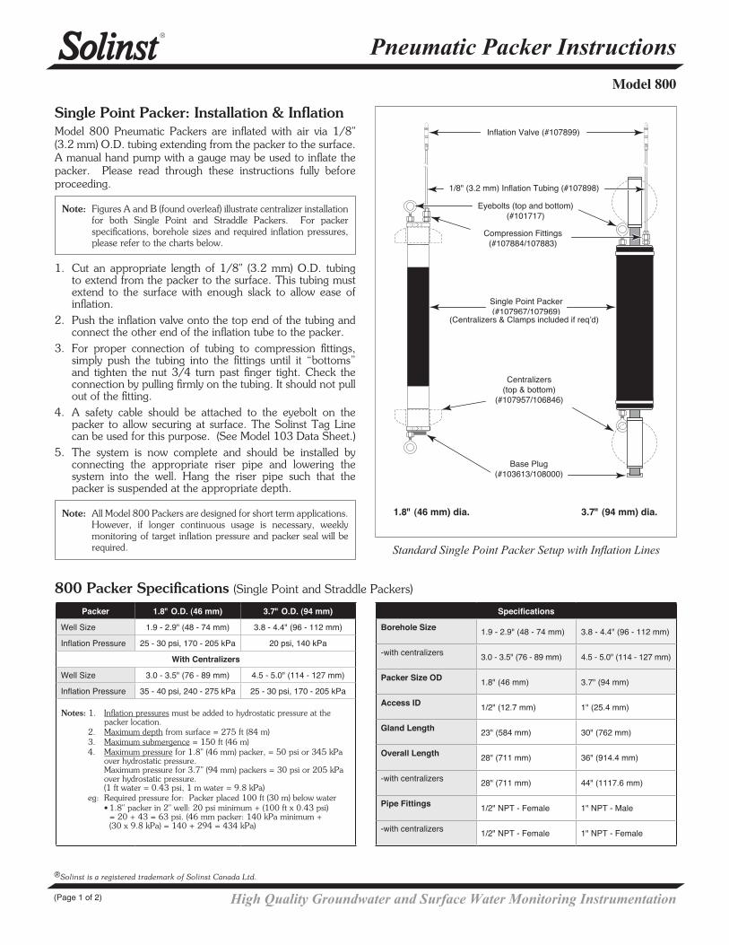
Inflation Valve (#107899)
1/8" (3.2 mm) Inflation Tubing (#107898)
Compression Fittings (#107884/107883)
Straddle Packer (#107966/107968)
Eyebolts (top & bottom) (#101717)
Inflation Tubing (#107898)
Straddle Pipe 1/2" dia./1" dia.
(available in 1 ft, 2ft, 3 ft lengths)
Single Point Packer (#107967/107969)
Centralizers (if required)(top & bottom)
(#107957/106846)Base Plug
(#103613/108000)
1.8" (46 mm) dia. 3.7" (94 mm) dia.
Standard Straddle Packer Setup with Inflation Lines
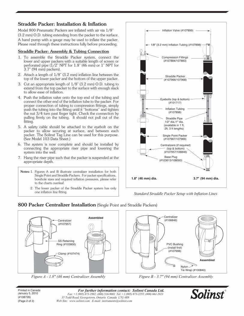
800 Packer Centralizer Installation (SinglePointandStraddlePackers)
Centralizer (#107957)
SS Retaining Ring (#103800)
Clamp (#107474)
Assembled Centralizer (#106846)
PVC Bushing (install first) (#107998)
Assembled
Nylon Tie Wrap (#100840)
Figure A - 1.8" (46 mm) Centralizer Assembly Figure B - 3.7" (94 mm) Centralizer Assembly