Embed Size (px)
Citation preview
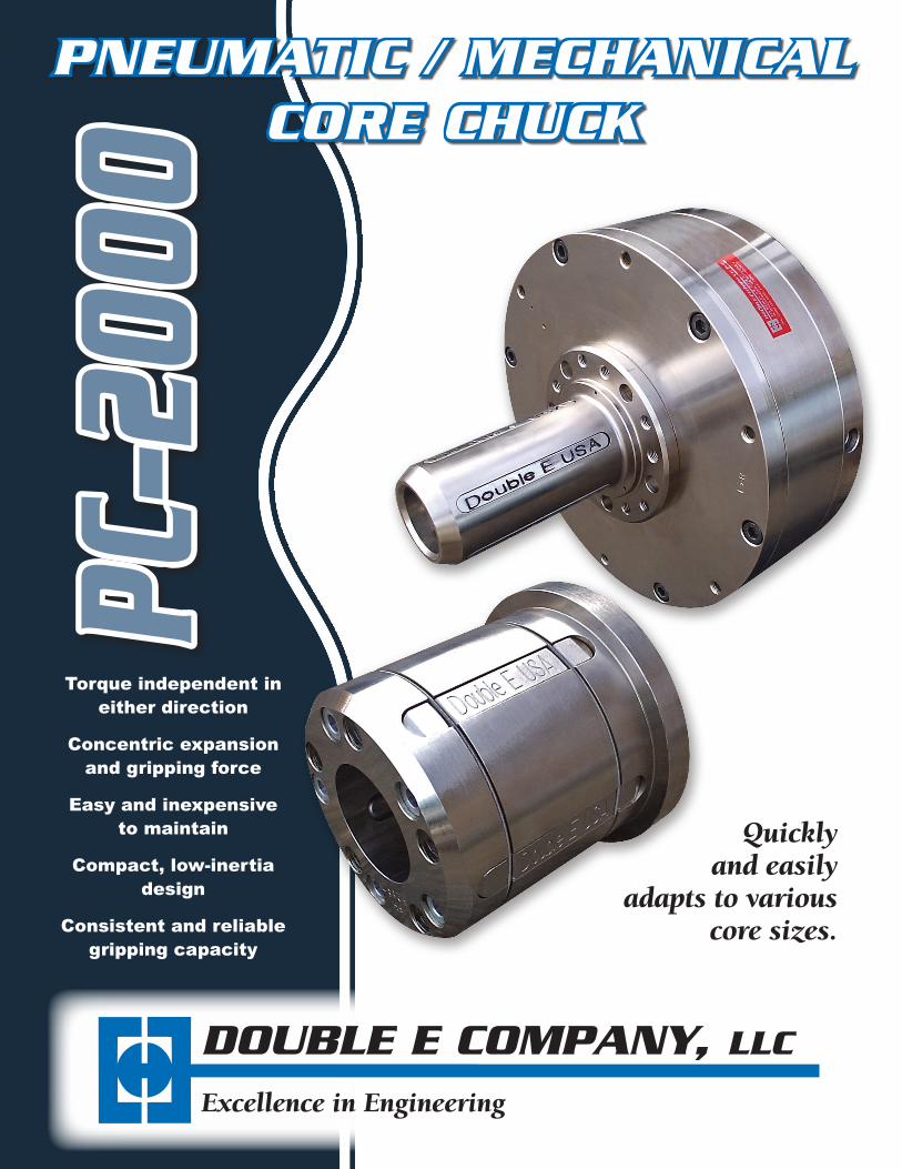
PNEUMATIC / MECHANICALCORE CHUCK
Torque independent in either direction
Concentric expansion and gripping force
Easy and inexpensive to maintain
Compact, low-inertia design
Consistent and reliable gripping capacity
Quickly and easily
adapts to various core sizes.
DOUBLE E COMPANY, LLC
Excellence in Engineering
PC–2
000
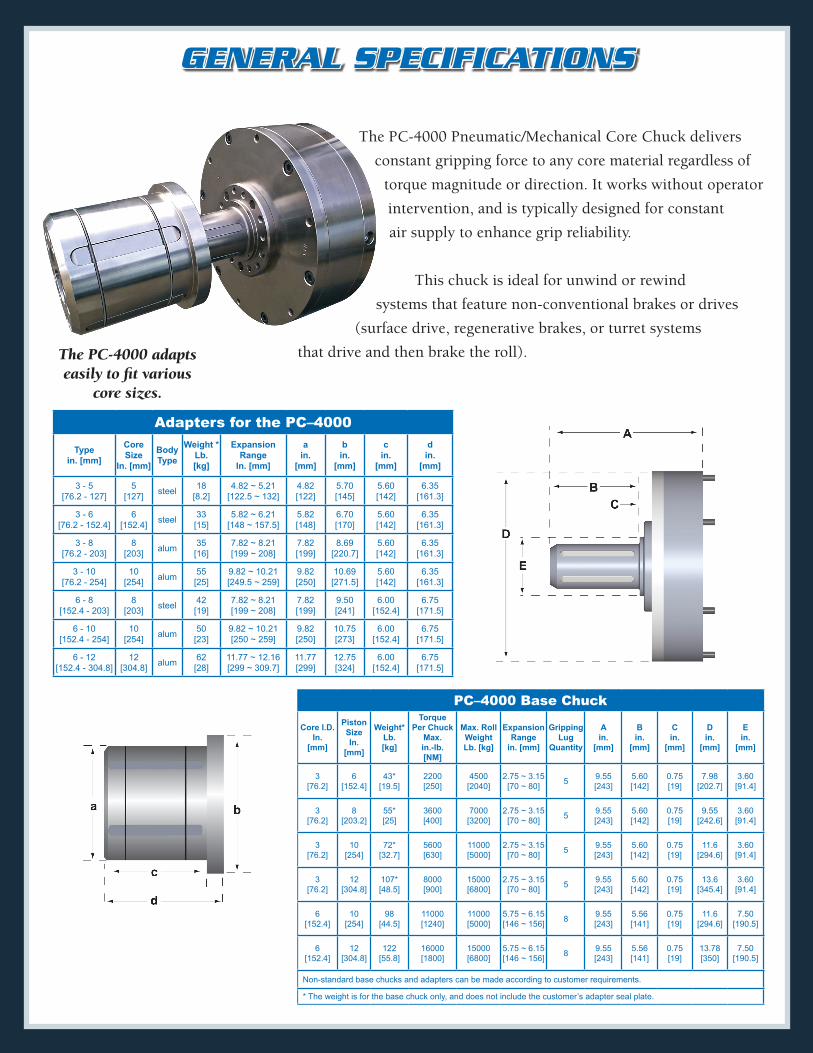
The PC-4000 Pneumatic/Mechanical Core Chuck delivers
constant gripping force to any core material regardless of
torque magnitude or direction. It works without operator
intervention, and is typically designed for constant
air supply to enhance grip reliability.
This chuck is ideal for unwind or rewind
systems that feature non-conventional brakes or drives
(surface drive, regenerative brakes, or turret systems
that drive and then brake the roll).The PC-4000 adapts easily to fit various
core sizes.
Adapters for the PC–4000
Type in. [mm]
Core Size
In. [mm]
Body Type
Weight * Lb. [kg]
Expansion Range
In. [mm]
a in.
[mm]
b in.
[mm]
c in.
[mm]
d in.
[mm]
3 - 5 [76.2 - 127]
5 [127] steel 18
[8.2]4.82 ~ 5.21
[122.5 ~ 132]4.82 [122]
5.70 [145]
5.60 [142]
6.35 [161.3]
3 - 6 [76.2 - 152.4]
6 [152.4] steel 33
[15]5.82 ~ 6.21
[148 ~ 157.5]5.82 [148]
6.70 [170]
5.60 [142]
6.35 [161.3]
3 - 8 [76.2 - 203]
8 [203] alum 35
[16]7.82 ~ 8.21 [199 ~ 208]
7.82 [199]
8.69 [220.7]
5.60 [142]
6.35 [161.3]
3 - 10 [76.2 - 254]
10 [254] alum 55
[25]9.82 ~ 10.21 [249.5 ~ 259]
9.82 [250]
10.69 [271.5]
5.60 [142]
6.35 [161.3]
6 - 8 [152.4 - 203]
8 [203] steel 42
[19]7.82 ~ 8.21 [199 ~ 208]
7.82 [199]
9.50 [241]
6.00 [152.4]
6.75 [171.5]
6 - 10 [152.4 - 254]
10 [254] alum 50
[23]9.82 ~ 10.21 [250 ~ 259]
9.82 [250]
10.75 [273]
6.00 [152.4]
6.75 [171.5]
6 - 12 [152.4 - 304.8]
12 [304.8] alum 62
[28]11.77 ~ 12.16 [299 ~ 309.7]
11.77 [299]
12.75 [324]
6.00 [152.4]
6.75 [171.5]
PC–4000 Base Chuck
Core I.D. In.
[mm]
Piston Size In.
[mm]
Weight* Lb. [kg]
Torque Per Chuck
Max. in.-lb. [NM]
Max. Roll Weight Lb. [kg]
Expansion Range
in. [mm]
Gripping Lug
Quantity
A in.
[mm]
B in.
[mm]
C in.
[mm]
D in.
[mm]
E in.
[mm]
3 [76.2]
6 [152.4]
43* [19.5]
2200 [250]
4500 [2040]
2.75 ~ 3.15 [70 ~ 80] 5 9.55
[243]5.60 [142]
0.75 [19]
7.98 [202.7]
3.60 [91.4]
3 [76.2]
8 [203.2]
55* [25]
3600 [400]
7000 [3200]
2.75 ~ 3.15 [70 ~ 80] 5 9.55
[243]5.60 [142]
0.75 [19]
9.55 [242.6]
3.60 [91.4]
3 [76.2]
10 [254]
72* [32.7]
5600 [630]
11000 [5000]
2.75 ~ 3.15 [70 ~ 80] 5 9.55
[243]5.60 [142]
0.75 [19]
11.6 [294.6]
3.60 [91.4]
3 [76.2]
12 [304.8]
107* [48.5]
8000 [900]
15000 [6800]
2.75 ~ 3.15 [70 ~ 80] 5 9.55
[243]5.60 [142]
0.75 [19]
13.6 [345.4]
3.60 [91.4]
6 [152.4]
10 [254]
98 [44.5]
11000 [1240]
11000 [5000]
5.75 ~ 6.15 [146 ~ 156] 8 9.55
[243]5.56 [141]
0.75 [19]
11.6 [294.6]
7.50 [190.5]
6 [152.4]
12 [304.8]
122 [55.8]
16000 [1800]
15000 [6800]
5.75 ~ 6.15 [146 ~ 156] 8 9.55
[243]5.56 [141]
0.75 [19]
13.78 [350]
7.50 [190.5]
Non-standard base chucks and adapters can be made according to customer requirements.
* The weight is for the base chuck only, and does not include the customer’s adapter seal plate.
GENERAL SPECIFICATIONS
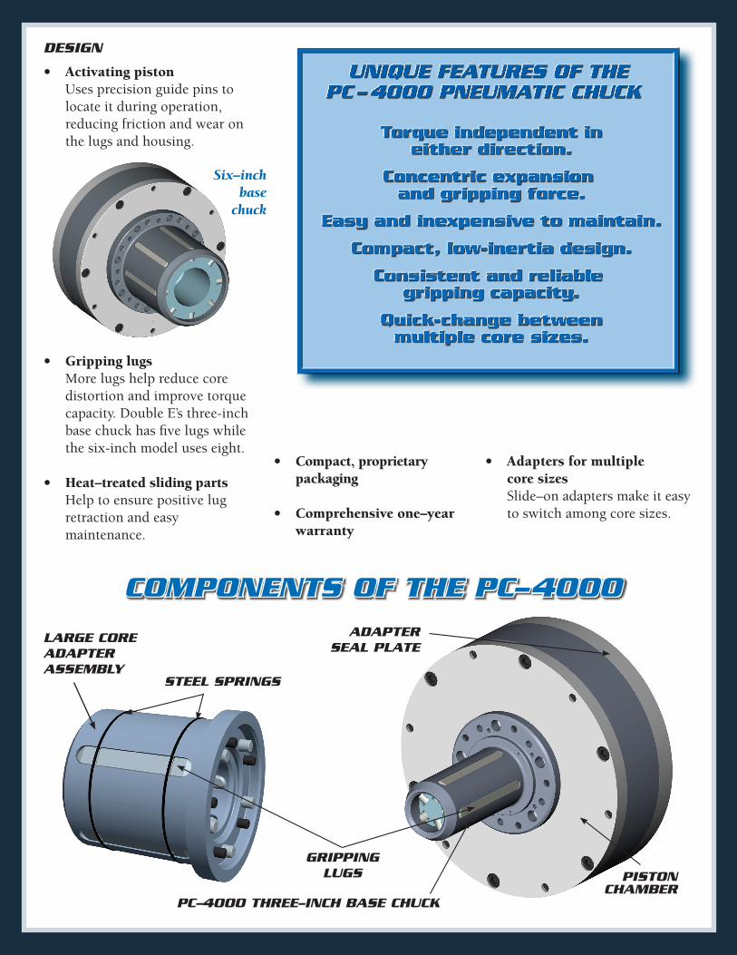
COMPONENTS OF THE PC–4000
• Activatingpiston Uses precision guide pins to locate it during operation, reducing friction and wear on the lugs and housing.
LARGE COREADAPTER ASSEMBLY
PC–4000 THREE–INCH BASE CHUCK
GRIPPING LUGS
STEEL SPRINGS
ADAPTER SEAL PLATE
DESIGN
• Grippinglugs More lugs help reduce core distortion and improve torque capacity. Double E’s three-inch base chuck has five lugs while the six-inch model uses eight.
• Heat–treatedslidingparts Help to ensure positive lug retraction and easy maintenance.
• Compact,proprietary packaging
• Comprehensiveone–year warranty
• Adaptersformultiple coresizes Slide–on adapters make it easy to switch among core sizes.
Six–inch base
chuck
PISTON CHAMBER
DOUBLE E COMPANY, LLC
www.doubleeusa.com
319ManleyStreet,WestBridgewater,MA02379USATel:(508)588-8099Fax:(508)[email protected]
EA
Excellence in Engineering
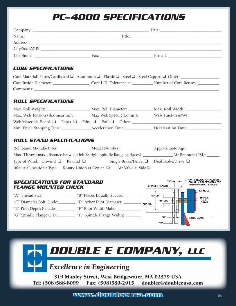
PC–4000 SPECIFICATIONS
ROLL SPECIFICATIONS
Max. Roll Weight:_____________________ Max. Roll Diameter: ____________ Max. Roll Width: _________________
Max. Web Tension (lb./linear in.): _______ Max Web Speed (ft./min.): _______ Web Thickness/Wt.: ______________
Web Material: Board ❑ Paper ❑ Film ❑ Foil ❑ Other: __________________________________________
Min. Emer. Stopping Time: _____________ Acceleration Time: _____________ Deceleration Time: _______________
CORE SPECIFICATIONS
Core Material: Paper/Cardboard ❑ Aluminum ❑ Plastic ❑ Steel ❑ Steel Capped ❑ Other: __________________
Core Inside Diameter: _________________ Core I. D. Tolerance ±: __________ Number of Core Reuses: __________
Comments: _______________________________________________________________________________________
Company: _______________________________________________________ Date: _____________________________
Name: ____________________________________________ Title: ___________________________________________
Address: __________________________________________________________________________________________
City/State/ZIP: _____________________________________________________________________________________
Telephone: __________________________ Fax: _________________________ E-mail: _________________________
SPECIFICATIONS FOR STANDARD FLANGE MOUNTED CHUCK
“A” Thread Size: _______________ “B” Places Equally Spaced: __________
“C” Diameter Bolt Circle:________ “D” Arbor Pilot Diameter: __________
“E” Pilot Depth Female: _________ “F” Pilot Width Male: ______________
“G” Spindle Flange O.D.: ________ “H” Spindle Flange Width: _________
ROLL STAND SPECIFICATIONS
Roll Stand Manufacturer: _______________ Model Number:________________ Approximate Age: ________________
Max. Throw (max. distance between left & right spindle flange surfaces): ______________ Air Pressure (PSI): ______
Type of Wind: Unwind ❑ Rewind ❑ Single Brake/Drive ❑ Dual Brake/Drive ❑
Inlet Air Location / Type: Rotary Union at Center ❑ Air Valve at Side ❑