Embed Size (px)
Citation preview

FABRICATION OF MATERIAL CONVEYING
SYSTEM USING PNEUMATIC CYLINDER
Submitted in partial fulfillment for the requirements for the award
of the degree of the
BACHELOR OF TECHNOLOGY
(MECHANICAL ENGINEERING)
By
KBALAJI 081131201026
KBASKARAN 081131201038
VDHANASEKAR 081131201054
RDHIVAKAR 081131201057
DrMGR EDUCATIONAL AND RESEARCH INSTITUTE
(Dr MGR DEEMED UNIVERSITY) MADURAVOYALCHENNAI-600 095
NAME helliphelliphelliphelliphelliphelliphelliphelliphelliphelliphelliphelliphellip
REG NO helliphelliphelliphelliphelliphelliphelliphelliphelliphelliphelliphelliphellip
SEC helliphelliphelliphelliphelliphelliphelliphelliphelliphelliphelliphelliphelliphelliphellip
DEPARTMENT helliphelliphelliphelliphelliphelliphelliphelliphelliphellip
Dr MGR Educational and Research Institute
(Dr M G R University)
Maduravoyal Chennai ndash 600 095
November 2012
Dr MGR EDUCATIONAL AND RESEARCH INSTITUTE
Dr MGR UNIVERSITY
DEPARTMENT OF MECHANICAL ENGINEERING
CHENNAI ndash 600 095 DrMGR EDUCATIONAL AND RESEARCH INSTITUTE
(Dr MGR DEEMED UNIVERSITY) MADURAVOYALCHENNAI-600 095
NAME helliphelliphelliphelliphelliphelliphelliphelliphelliphelliphelliphelliphellip
REG NO helliphelliphelliphelliphelliphelliphelliphelliphelliphelliphelliphelliphellip
SEC helliphelliphelliphelliphelliphelliphelliphelliphelliphelliphelliphelliphelliphelliphellip
DEPARTMENT helliphelliphelliphelliphelliphelliphelliphelliphelliphellip
BONAFIDE CERTIFICATE
This is to certify that the project work entitled
ldquoFABRICATION OF MATERIAL CONVEYING SYSTEM
USING PNEUMATIC CYLINDERrdquo is a bonafide record of project work
done by
KBALAJI 081131201026
KBASKARAN 081131201038
VDHANAASEKAR 081131201054
RDHIVAKAR 081131201057
Students of BTech (Mechanical) during the academic year 2012-2013
(Signature of the supervisor) (Signature of the Head of the Department)
Mr G Rajamahendran BE(ME) Professor Mr M Ganesan Lecturer Dept of Mechanical Engineering
Dept of Mechanical Engineering Dr MGR university
Dr MGR university
Submitted for the project Viva-Voice Examination held on ----------------
Internal Examiner External Examiner
AAACCCKKKNNNOOOWWWLLLEEEDDDGGGEEEMMMEEENNNTTT
We wish to expand our sincere thanks and our whole-hearted gratitude
to the following persons At the outset we would like to convey our grateful
thanks to our Chairman Mr AC Shanmugam our Pro-Chancellor Mr
ACS Arun Kumar our Vice-Chancellor DrPadmanaban We profusely
thank Prof Mr Ganeshan Head of the Department Mechanical
Engineering for his imperceptible guidance and implications without which
our project would not have been sculpted successfully
We express our heartfelt thanks to Mr Rajamahendran for his
invaluable guidance utmost patience inspirational coordination and
constant encouragement in completing this project successfully
We would like to thank all the staff members students and parents
who have helped us to complete our project as scheduled
CONTENTS
CONTENTS
Chapter No TITLE
1 INTRODUCTION
2 SYNOPSIS
3 CONSTRUCTION
4 WORKING PRINCIPLE
5 MECHANICAL ASSEMBLY DIAGRAM
6 PNEUMATIC COMPONENTS DETAILS
7 PNEUMATIC CIRCUIT DIAGRAM
8 ADVANTAGES
9 APPLICATION
10 FINISHING AND PAINTING
11 COST ESTIMATION
12 CONCLUSION
13 BIBILOGRAPHY
14 PHOTO VIEW
INTRODUCTION
INTRODUCTION
In our technical education the project work plays a major role Every
students is put in to simulated life particularly where the student required to
bring his knowledge skill and experience of the project work
It helps how to evolve specifications under given constrains by
systematic approach to the problem a construct a work device Project work
thus integrates various skills and knowledge attainment during study and
gives orientation towards application
As the students solve the various problems exposed by the project
work the students get the confidence to overcome such problems in the
future life It helps in expanding the thinking and alternatives for future
applications
SYNOPSIS
SYNOPSIS
To increase the productivity and to overcome skilled labour shortage
most of the manufacturing industries are going for automation The main
aim for us to select the project work is to acquire practical knowledge in the
field of automation using Pneumatic system
We selected ldquo FABRICATION OF MATERIAL CONVEYING SYSTEM
USING PNEUMATIC CYLINDER rdquo as our project work and we used
principles of converting linear reciprocating motion into rotary motion in
developing this project work the material handling mechanism is achieved
by reciprocating the double acting cylinder which is controlled by solenoid
operated 52 way DC valve which is actuated by ONOFF relay control
system Here the linear motion of the piston rod is converted to rotary
motion of the belt conveyor through the chain and sprocket wheel
Mechanism
Moreover the same set up can be modified to automatic vibrating
machine by simply removing the rotary mechanism and attaching a box or
container to the piston end rod
CONSTRUCTION
DETAILS
CONSTRUCTION
This project consists of
1) Belt conveyor assembly
2) ONOFF relay control
3) 24VDC power supply
4) Chain with sprocket assembly
5) Pneumatic cylinder with solenoid valve
1MS SQUARE CHANNEL FRAME STAND
This MS square angle frame Base stand is fabricated to a size of 450
mm x 900 mm x 500 mm ( L X BX H) and is made with MSsquare
channel material of 18mm X 18mm size having 3mm thickness All the
above components are kept inside the stand Four wheels are fitted at the
bottom for its movement The figure shows the fabricated stand
Belt conveyor assembly
The belt of 40mm width and 1000mm circumference of nylon
material is rotated by the cycle wheel sprocket
4PNEUMATIC CYLINDER UNIT
In this unit one air cylinder is used to push the chain in order to
rotate the sprocket wheel One cylinder is mounted at the bottom of the
wheel The size of the cylinder is 20 dia X 100 MM stroke The cylinder
port AB is connected to the directional control valve of the AB port
through the flow control valve
5CONTROL VALVE
Here two 52 way lever operated DC valve is used for actuating the double
acting cylinder
When the valve is turned ON the 52 way DC valve
directs the air to the air cylinder and the the piston push the job on
the conveyor or eject the job from the conveyor The piston rod is
return to original position when the valve is turned OFF
The sprocket wheel is rotated by a another cylinder which is actuated
through the 52 way solenoid operated directional control valve
FLOW CONTROL VALVE
This flow control valve is used to control the speed of the piston
movement in the cylinder Two flow control valves are mounted on
each port of A and B of the cylinder jack unitThe below figure shows
the flow control valve
6ELECTRICAL RELAY PANEL
The electrical wiring diagram is shown below
ONOFF relay control
RELAY
SPECPCATION OF RELAY
a) Nature of supply dc
b) Coil voltage 12v
c) No of NO and NC contacts 1
d) No of poles single pole double throw
e) Shape of contact point flat
f) Contact point material silver or silver alloy
g) Type of relay electro dynamic
The 52 way solenoid operated directional control valve is controlled
by the ONOFF relay control system and hence the cylinder piston rod
reciprocated continuously
24VDC power supply
This power supply supplies the 24VDC power to the solenoid coil in the 52
way solenoid operated directional control valve
Chain with sprocket assembly
The piston end rod is connected to the wooden block on which a
chain of small length is fixed in straight horizontal position The chain and
the cylinder assembly set up on a lengthy wooden block and its height can
be adjusted to fit the ratchet wheel with the help of four vertical bolt
ampscrews Ratched wheel is attached to the driving cycle wheel from which
the motion transmitted to the driven wheel through the nylon belt
Pneumaticsystem
The double acting cylinder is mounted on the plywood board of size
600 x 450 mm using a U- bracket at both the ends placed under the belt
conveyor
The 52 way solenoid operated Direction control valve is fixed on the
Novapan board using a screw head bolts The pressurized air is connected to
the input port bdquop‟ of solenoid valve The output port is connected to the
double acting cylinder
The inlet of the solenoid valve is connected to the compressor tank
through FRL unit after setting the pressure to 5 barA 24V DC supply is
provided to the solenoid coil through the ONOFF relay from the DC power
supply
WORKING PRINCIPLE
WORKING PRINCIPLE
Before starting the operation of material handling system set the working
pressure to 5 bar from the compressor outlet Connect the 230 AC power
supply to the female electrical plug in order to supply the electrical power to
the relay control system and hence the solenoid valve direct the air supply
to the double acting cylinder The piston in the air cylinder reciprocate to
and fro
When the solenoid coil is ON the valve changed the direction of air to the
double acting cylinder Thus the valve reciprocates to and fro continuously
till power is cut off This reciprocate motion is converted to rotary motion
with help of ratchet wheel mechanism and the nylon belt moves over the
driving and driven pulley
The above arrangement can be modified to working as a
VIBRATOR by simply connecting the any other unit to the piston end
rod
INTRODUCTION TO
PNEUMATICS
INTRODUCTION TO PNEUMATICS
In engineering field may Machines make use of a fluid or compressed air to
develop a force to move or hold an object
A system which is operated by compressed air is known as Pneumatic
System It is most widely used the work Piece turning drilling sawing etc
By the use of Pneumatic System the risk of explosion on fire with
compressed air is minimum high working speed and simple in construction
PNEUMATIC COMPONENTS
In engineering field many machines make use of fluid for developing
a force to move or hold an object A number of fluid can be used in
devices and system Two commonly used fluids are oil and compressed
air A system which is operated by compressed air A system which is
operated by compressed air is know as pneumatic system
AIR COMPRESSOR
Compressor is a device which gets air fro the atmosphere and
compresses it for increasing the pressure of air Thus the compressed air
Thus the compressed air used for many application
The compression process requires work in put Hence a compressor is
driven by a prime mover Generally an electric motor is used as prime
mover The compressed air from compressor is stored in vessel called
reservoir Fro reservoir it be conveyed to the desired place through pipe
lines
2 FLTER
In pneumatic system an air filter is used to remove all foreign matter
An air filter dry clean air to flow without resistance various materials are
used for the filter element The air may be passed thorugh a piece metal a
pours stone felt resin impregnated paper In some filters centrifugal action
or cyclone action is used to remove foreign matters
3 PRESSURE REGULATOR
Constant pressure level is required for the trouble free operation of a
pneumatic control A pressure regulator is fitted downstream of the
compressed air filter It provides a constant set pressure at the outlet of the
outlet of the regulator The pressure regulator is also called as pressure
reducing valve or pressure regulating valve
4 LUBRICATOR
The purpose of an air lubricator is to provide the pneumatic
components with sufficient lubricant These lubricants must reduce the wear
of the moving parts reduce frictional forces and protect the equipment from
corrosion
Care should be taken to ensure that sufficient lubrication is provided
But excessive lubrication should be avoided
5 FLR Package (or) FRL Package
The air service unit is a combination of following units
1 Compressed air filter
2 Compressed air regulator
3 Compressed air lubricator
Air Filter regulator and lubricator are connected together with close
nipples as one package This unit is know as FLR (Filter regulator
lubricator)
6 PRESSURE CONTROL VALVE
Each hydraulic system is used to operate in a certain pressure range
Higher pressure causes damage of components To avoid this pressure
control valves are fitted in the circuits
7 Direction control valve
Directional control valves are used to control the direction of flow
The design principle is a major factor with regard to service life actuating
force switching times etc
8 Piston and Cylinder
single acting pneumatic cylinder
PNEUMATIC CITCUIT SYMBOL FOR SINGLE ACTING PNEUMATIC
CYLINDER
Pneumatic cylinders (sometimes known as air cylinders) are mechanical
devices which produce force often in combination with movement and are
powered by compressed gas (typically air)
To perform their function pneumatic cylinders impart a force by converting
the potential energy of compressed gas into kinetic energy This is achieved
by the compressed gas being able to expand without external energy input
which itself occurs due to the pressure gradient established by the
compressed gas being at a greater pressure than the atmospheric pressure
This air expansion forces a piston to move in the desired direction The
piston is a disc or cylinder and the piston rod transfers the force it develops
to the object to be moved
When selecting a pneumatic cylinder you must pay attention to
how far the piston extends when activated known as stroke
surface area of the piston face known as bore size
action type
pressure rating such as 50 PSI
type of connection to each port such as 14 NPT
must be rated for compressed air use
mounting method
Types
Although pneumatic cylinders will vary in appearance size and function
they generally fall into one of the specific categories shown below However
there are also numerous other types of pneumatic cylinder available many
of which are designed to fulfill specific and specialised functions
Single acting cylinders
Single acting cylinders (SAC) use the pressure imparted by compressed air
to create a driving force in one direction (usually out) and a spring to return
to the home position
Double acting cylinders
Double Acting Cylinders (DAC) use the force of air to move in both extend
and retract strokes They have two ports to allow air in one for outstroke
and one for instroke
Other types
Although SACs and DACs are the most common types of pneumatic
cylinder the following types are not particularly rare
Rotary air cylinders actuators that use air to impart a rotary motion
Rodless air cylinders These have no piston rod They are actuators
that use a mechanical or magnetic coupling to impart force typically
to a table or other body that moves along the length of the cylinder
body but does not extend beyond it
Sizes
Air cylinders are available in a variety of sizes and can typically range from
a small 25 mm air cylinder which might be used for picking up a small
transistor or other electronic component to 400 mm diameter air cylinders
which would impart enough force to lift a car Some pneumatic cylinders
reach 1000 mm in diameter and are used in place of hydraulic cylinders for
special circumstances where leaking hydraulic oil could impose an extreme
hazard
Pressure radius area and force relationships
Although the diameter of the piston and the force exerted by a cylinder are
related they are not directly proportional to one another Additionally the
typical mathematical relationship between the two assumes that the air
supply does not become saturated Due to the effective cross sectional area
reduced by the area of the piston rod the instroke force is less than the
outstroke force when both are powered pneumatically and by same supply of
compressed gas
The relationship between force on outstroke pressure and radius is as
follows
This is derived from the relationship between force pressure and effective
cross-sectional area which is
F = p A
With the same symbolic notation of variables as above but also A represents
the effective cross sectional area
On instroke the same relationship between force exerted pressure and
effective cross sectional area applies as discussed above for outstroke
However since the cross sectional area is less than the piston area the
relationship between force pressure and radius is different The calculation
isnt more complicated though since the effective cross sectional area is
merely that of the piston less that of the piston rod
For instroke therefore the relationship between force exerted pressure
radius of the piston and radius of the piston rod is as follows
Where
F represents the force exerted
r1 represents the radius of the piston
r2 represents the radius of the piston rod
π is pi approximately equal to 314159
VALVE CONNECTORS
POLYURETHANE TUBE shortly say PUN tube
Manual operations involving heavy lifting Pushing or pulling
motions can be firing for the operations and can induce a monotony which
results in lowered production Cylinders have been designed to carry out
these movements with a pre ndash determined force and stroke and can be fitted
to synchronize with operation cycles of many machines it is worth wile to
examine the existing plan and methods of movement and to consider the
numberous mechanical applications which the range of pneumatic cylinders
make possible Quality is to keynote of air cylinder Engineer them into
you production setup to get the last ounce of power speed and efficiency to
save time space and money
Piston is cylinder part which moves in a cylinder have corresponding
hole on it To make the strokes effective there is no gap between them or
with a very tiny gap part of the micron The cylinder and its piston have a
glazing surface where there is a contact between them for easy motion of
piston and avoiding wear and tear of both The outer side of the cylinder
have mountings consists of plate and studs attached with it But the of these
mountings the cylinder and piston assembly can fitted on any place of the
piston have threads on it for fastening theother parts (or) accessories
according the operating performed and the application required We can fit
holding devices Clamping materials or other metal cutting and forming
ports with which can be movable with the piston
Pneumatics are used practically in every industry for a wide variety of
manufacturing process pneumatics equipments are used for multiple
reasons The best reason is that it is air powered ordinary air turns out to be
very excellent as a fluid power components
Solenoid Valve
In order to automate the air flow in our system we have to provide an
electrically controlled valves Electrical devices can provide more effective
control less expensive interlocks having many additional safety features and
simplified automatic sequencing when a machine must operate in a
hazardous area remote actuation is a desirable The operator can provide
satisfactory control though electrical devices from a remote point with in a
safe area uding a semi automatic system and these electrical flow control
devices are also in use in full automation by providing proper action signals
Push and pull actuation can be priced b solenoids These movements
are used to open and close the pop pet type valves These actuations are
done according to the signals given to the solenoid coil when the decided by
the program The outlet of solenoiud coil when the decided by the program
The outlet of solenoid valve is connected to a spray gun which is going to
spray the paint
SOLENOID OPERATED VALVES
Solenoid valves are electromechanical devices like relays and
contractors A solenoid valve is used to obtain mechanical movement in
machinery by utilizing fluid or air pressure The fluid or air pressure is
applied to the cylinder piston through a valve operated by a cylindrical
electrical coil The electrical coil along with its frame and plunger is known
as the solenoid and the assembly of solenoid and mechanical valve is known
as solenoid valve The solenoid valve is thus another important
electromechanical device used in control of machines Solenoid valves are
of two types
1 Single solenoid spring return operating valve(52)
2 Double solenoid operating valve
In fig 1 is shown a single solenoid spring return valve in its de-energized
condition The symbol for the solenoid and the return are also shown The
solenoid valve is shown connected to the cylinder to help readers understand
the solenoid valve action In the de energized condition the plunger and the
valve spool position as shown in figure 1
52 WAY VALVE
In this position of spool port P is connected to port A and port B is
connected to tank or exhaust (ie atmosphere) if air is used Spring pressure
(S) keeps the spool in this condition as long as the coil is de energized
Fluid pressure from port P through port A is applied to the left side of the
cylinder piston Thus the cylinder piston moves in the right direction Now
when the solenoid coil is energized plunger is attracted and it pushes the
spool against spring pressure
The new position of plunger and spool are shown in fig 2
In this position of spool port A gets connected to tank and port P gets
connected to port B Thus pressure is applied to the cylinder piston from
right and moves the piston rod to the left At the same time fluid in the other
side is drained out to the tank When the solenoid coil is again de energized
the spring (S) will move the spool to its original position as shown in figure
1 Thus normally when the solenoid coil is de energized the piston rod
remains extended
PNEUMATIC
FITTING
PNEUMATIC FITTINGS
There are no nuts to tighten the tube to the fittings as in the
conventional type of metallic fittings The tube is connected to the
fitting by a simple push ensuring leak proof connection and can be
released by pressing the cap and does not require any special tooling
like spanner to connect (or) disconnect the tube from the fitting
SPECIFICATION OF THE FITTING
Body Material - Plastic
CollectThread Nipple - Brass
Seal - Nitrate Rubber
Fluid Used - Air
Max Operating Pressure - 7 Bar
Tolerance on OD of the tubes - 1 mm
Min Wall thickness of tubes - 1 mm
FLEXIBLE HOSES
The Pneumatic hoses which is used when pneumatic
components such as actuators are subjected to movement Hose is
fabricated in layer of
Elastomer or synthetic rubber which permits operation at high
pressure The standard outside diameter of tubing is 116 inch If the
hose is subjected to rubbing it should be encased in a protective
sleeve
ADVANTAGES AND LIMITATIONS
ADVANTAGES
The Pneumatic arm is more efficient in the technical field
Quick response is achieved
Simple in constructions
Easy to maintain and repair
Cost of the unit is less when compared to other robotics
No fire hazard problem due to over loading
Comparatively the operation cost is less
The operation of arm is faster because the media to operate is air
Continuous operation is possible without stopping
LIMITATIONS
High torque cannot be obtained
Load Carrying capacity of this unit is not very high (3 ndash 5 kgs)
Silencer may be used to reduce the noise of compressed air
APPLICATION
1) DISCHARGE OF WORKPIECE
The arm fed has wide application in low cost automation It can be
used in automated assembly lines to pick-up the finished product from
workstation and place them in the bins It can also be used to pick-up the
raw material and place them on the conveyor belts and vice versa
2) JOB CLAMPING
This unit can also be used in clamping operations in certain areas of
mass productions where clamping and unclamping have to be done at high
speeds The application of this unit is limited to operations which involves
moderate clamping forces
3) TRANSFER OF JOBS BETWEEN WORK STATIONS
The gripping method used in a low cost automation to move the work
piece from one workstation to another The combination of an angular
rotary motion is the principle behind this method The gripper holds the
work rigidly The to and fro motion is achieved by means of the actuating
cylinder
4) TOOL CHANGING APPLICATION
When the pneumatic arms are made smaller in size they can be used
in automatic tool changer in CNC turning and drilling machines by
attaching suitable tool holding device to the rotary cylinder
PNEUMATIC SPARE
PARTS DETAILS
PENUMATIC SPARE PARTS DETAITS
NAME OF THE PARTS SPECFICATION
1 Double acting cyclinder
( air max make )
2 single solenoid 52 way DCValve
3 ONOFF relay control
4 plywood board
5 Valve Connectors(5 Nos)
6 Plastic tube (5 metres)
7 pulley(two nos)
8ratchet wheel
9electrical plug
10nylon belt (40mmwidth)
20MM100MM
18 SIZE 24VDC
NO
12 MM 600450
18MM
6 x4 MM
40 mm
40mm
5amps230v ac
875mm
PNEUMATIC CIRCUIT
DIAGRAM
PNEUMATIC CIRCUIT DIAGRAM
ELECTRICAL
HARDWARE DETAILS
BLOCK DIAGRAM
12V
Power
supply
Interface
relay
START SWITCH
ONOFF
CONTROL
SOLENOID
VALVE
POWER SUPPLY UNIT
INTRODUCTION
All the electronic components starting from diode to Intel IC‟s only
work with a DC supply ranging from +5V to +12V We are utilizing for the
same the cheapest and commonly available energy source of 230V-50Hz
and stepping down rectifying filtering and regulating the voltage
STEP DOWN TRANSFORMER
When AC is applied to the primary winding of the power transformer
it can either be stepped down or stepped up depending on the value of DC
needed In our circuit the transformer of 230V12-0-12V is used to perform
the step down operation where a 230V AC appears as 24V AC across the
secondary winding Apart from stepping down voltages it gives isolation
between the power source and power supply circuitries
Power supply 24DC and 12v dc
A 24 ndash0 V step down transformer is used to step down 230V AC to
24V AC This 24V AC supply is converted to 24V DC using four rectifier
diodes The voltage from the rectifier section is regulated to 12V DC using
7812 IC This voltage is used for power supply for the ONOFF relay
control The power supply circuit is shown in fig
ELECTRICAL WIRING
DIAGRAM
M
P
N C
+ 24 V
PLC CONTACT
RELAY CIRCUIT
COST ESTIMATION
COST ESTIMATION
NAME OF THE PARTS PRICE
1 Double acting cyclinder 3 NOS
2 Single solenoid 52 way DCValve
3 Relay amp switch
4 MS STAND
5 Valve Connectors(5 Nosx 4000)
6 Plastic tube (2 metres)
7 CYLCLE wheel pulley(two nos)
8ratchet wheel
9electrical plug
10nylon belt (40mmwidth)
1152 WAY LEVER VALVE 2 NOS
TOTAL
400000
150000
150000
30000
30000
40000
20000
10000
40000
50000
160000
1080000
--------------------------------
CONCLUSION
CONCLUSION
We make this project entirely different from other projects Since
concepts involved in our project is entirely different that a single unit is used
to various purposes which is not developed by any of other team members
By doing this project we gained the knowledge of working of
pneumatic system and how automation can be effectively done with the help
of pneumatic system
It is concluded that any automation system can be done with the help
of electro pneumatic system
We have successfully completed the project work at our Institute
By doing this project work we understood the working principle and
uses of various valves switches relays etc
Once again we express our sincere thanks to our staff members
BIBILOGRAPHY
BIBILOGRAPHY
1 Low cost automation with pneumatics - FESTO
2 Electro pneumatics - FESTO
3 Hydraulics amp pneumatics for Power Production - Harry L ndash Stewart
4 Basic pneumatics - FESTO
5 wwwgooglecom
6 Workshop Technology - Hajra Chowdry
7 Production Technology -RS Khurmi
PHOTO VIEW

CONTENTS
CONTENTS
Chapter No TITLE
1 INTRODUCTION
2 SYNOPSIS
3 CONSTRUCTION
4 WORKING PRINCIPLE
5 MECHANICAL ASSEMBLY DIAGRAM
6 PNEUMATIC COMPONENTS DETAILS
7 PNEUMATIC CIRCUIT DIAGRAM
8 ADVANTAGES
9 APPLICATION
10 FINISHING AND PAINTING
11 COST ESTIMATION
12 CONCLUSION
13 BIBILOGRAPHY
14 PHOTO VIEW
INTRODUCTION
INTRODUCTION
In our technical education the project work plays a major role Every
students is put in to simulated life particularly where the student required to
bring his knowledge skill and experience of the project work
It helps how to evolve specifications under given constrains by
systematic approach to the problem a construct a work device Project work
thus integrates various skills and knowledge attainment during study and
gives orientation towards application
As the students solve the various problems exposed by the project
work the students get the confidence to overcome such problems in the
future life It helps in expanding the thinking and alternatives for future
applications
SYNOPSIS
SYNOPSIS
To increase the productivity and to overcome skilled labour shortage
most of the manufacturing industries are going for automation The main
aim for us to select the project work is to acquire practical knowledge in the
field of automation using Pneumatic system
We selected ldquo FABRICATION OF MATERIAL CONVEYING SYSTEM
USING PNEUMATIC CYLINDER rdquo as our project work and we used
principles of converting linear reciprocating motion into rotary motion in
developing this project work the material handling mechanism is achieved
by reciprocating the double acting cylinder which is controlled by solenoid
operated 52 way DC valve which is actuated by ONOFF relay control
system Here the linear motion of the piston rod is converted to rotary
motion of the belt conveyor through the chain and sprocket wheel
Mechanism
Moreover the same set up can be modified to automatic vibrating
machine by simply removing the rotary mechanism and attaching a box or
container to the piston end rod
CONSTRUCTION
DETAILS
CONSTRUCTION
This project consists of
1) Belt conveyor assembly
2) ONOFF relay control
3) 24VDC power supply
4) Chain with sprocket assembly
5) Pneumatic cylinder with solenoid valve
1MS SQUARE CHANNEL FRAME STAND
This MS square angle frame Base stand is fabricated to a size of 450
mm x 900 mm x 500 mm ( L X BX H) and is made with MSsquare
channel material of 18mm X 18mm size having 3mm thickness All the
above components are kept inside the stand Four wheels are fitted at the
bottom for its movement The figure shows the fabricated stand
Belt conveyor assembly
The belt of 40mm width and 1000mm circumference of nylon
material is rotated by the cycle wheel sprocket
4PNEUMATIC CYLINDER UNIT
In this unit one air cylinder is used to push the chain in order to
rotate the sprocket wheel One cylinder is mounted at the bottom of the
wheel The size of the cylinder is 20 dia X 100 MM stroke The cylinder
port AB is connected to the directional control valve of the AB port
through the flow control valve
5CONTROL VALVE
Here two 52 way lever operated DC valve is used for actuating the double
acting cylinder
When the valve is turned ON the 52 way DC valve
directs the air to the air cylinder and the the piston push the job on
the conveyor or eject the job from the conveyor The piston rod is
return to original position when the valve is turned OFF
The sprocket wheel is rotated by a another cylinder which is actuated
through the 52 way solenoid operated directional control valve
FLOW CONTROL VALVE
This flow control valve is used to control the speed of the piston
movement in the cylinder Two flow control valves are mounted on
each port of A and B of the cylinder jack unitThe below figure shows
the flow control valve
6ELECTRICAL RELAY PANEL
The electrical wiring diagram is shown below
ONOFF relay control
RELAY
SPECPCATION OF RELAY
a) Nature of supply dc
b) Coil voltage 12v
c) No of NO and NC contacts 1
d) No of poles single pole double throw
e) Shape of contact point flat
f) Contact point material silver or silver alloy
g) Type of relay electro dynamic
The 52 way solenoid operated directional control valve is controlled
by the ONOFF relay control system and hence the cylinder piston rod
reciprocated continuously
24VDC power supply
This power supply supplies the 24VDC power to the solenoid coil in the 52
way solenoid operated directional control valve
Chain with sprocket assembly
The piston end rod is connected to the wooden block on which a
chain of small length is fixed in straight horizontal position The chain and
the cylinder assembly set up on a lengthy wooden block and its height can
be adjusted to fit the ratchet wheel with the help of four vertical bolt
ampscrews Ratched wheel is attached to the driving cycle wheel from which
the motion transmitted to the driven wheel through the nylon belt
Pneumaticsystem
The double acting cylinder is mounted on the plywood board of size
600 x 450 mm using a U- bracket at both the ends placed under the belt
conveyor
The 52 way solenoid operated Direction control valve is fixed on the
Novapan board using a screw head bolts The pressurized air is connected to
the input port bdquop‟ of solenoid valve The output port is connected to the
double acting cylinder
The inlet of the solenoid valve is connected to the compressor tank
through FRL unit after setting the pressure to 5 barA 24V DC supply is
provided to the solenoid coil through the ONOFF relay from the DC power
supply
WORKING PRINCIPLE
WORKING PRINCIPLE
Before starting the operation of material handling system set the working
pressure to 5 bar from the compressor outlet Connect the 230 AC power
supply to the female electrical plug in order to supply the electrical power to
the relay control system and hence the solenoid valve direct the air supply
to the double acting cylinder The piston in the air cylinder reciprocate to
and fro
When the solenoid coil is ON the valve changed the direction of air to the
double acting cylinder Thus the valve reciprocates to and fro continuously
till power is cut off This reciprocate motion is converted to rotary motion
with help of ratchet wheel mechanism and the nylon belt moves over the
driving and driven pulley
The above arrangement can be modified to working as a
VIBRATOR by simply connecting the any other unit to the piston end
rod
INTRODUCTION TO
PNEUMATICS
INTRODUCTION TO PNEUMATICS
In engineering field may Machines make use of a fluid or compressed air to
develop a force to move or hold an object
A system which is operated by compressed air is known as Pneumatic
System It is most widely used the work Piece turning drilling sawing etc
By the use of Pneumatic System the risk of explosion on fire with
compressed air is minimum high working speed and simple in construction
PNEUMATIC COMPONENTS
In engineering field many machines make use of fluid for developing
a force to move or hold an object A number of fluid can be used in
devices and system Two commonly used fluids are oil and compressed
air A system which is operated by compressed air A system which is
operated by compressed air is know as pneumatic system
AIR COMPRESSOR
Compressor is a device which gets air fro the atmosphere and
compresses it for increasing the pressure of air Thus the compressed air
Thus the compressed air used for many application
The compression process requires work in put Hence a compressor is
driven by a prime mover Generally an electric motor is used as prime
mover The compressed air from compressor is stored in vessel called
reservoir Fro reservoir it be conveyed to the desired place through pipe
lines
2 FLTER
In pneumatic system an air filter is used to remove all foreign matter
An air filter dry clean air to flow without resistance various materials are
used for the filter element The air may be passed thorugh a piece metal a
pours stone felt resin impregnated paper In some filters centrifugal action
or cyclone action is used to remove foreign matters
3 PRESSURE REGULATOR
Constant pressure level is required for the trouble free operation of a
pneumatic control A pressure regulator is fitted downstream of the
compressed air filter It provides a constant set pressure at the outlet of the
outlet of the regulator The pressure regulator is also called as pressure
reducing valve or pressure regulating valve
4 LUBRICATOR
The purpose of an air lubricator is to provide the pneumatic
components with sufficient lubricant These lubricants must reduce the wear
of the moving parts reduce frictional forces and protect the equipment from
corrosion
Care should be taken to ensure that sufficient lubrication is provided
But excessive lubrication should be avoided
5 FLR Package (or) FRL Package
The air service unit is a combination of following units
1 Compressed air filter
2 Compressed air regulator
3 Compressed air lubricator
Air Filter regulator and lubricator are connected together with close
nipples as one package This unit is know as FLR (Filter regulator
lubricator)
6 PRESSURE CONTROL VALVE
Each hydraulic system is used to operate in a certain pressure range
Higher pressure causes damage of components To avoid this pressure
control valves are fitted in the circuits
7 Direction control valve
Directional control valves are used to control the direction of flow
The design principle is a major factor with regard to service life actuating
force switching times etc
8 Piston and Cylinder
single acting pneumatic cylinder
PNEUMATIC CITCUIT SYMBOL FOR SINGLE ACTING PNEUMATIC
CYLINDER
Pneumatic cylinders (sometimes known as air cylinders) are mechanical
devices which produce force often in combination with movement and are
powered by compressed gas (typically air)
To perform their function pneumatic cylinders impart a force by converting
the potential energy of compressed gas into kinetic energy This is achieved
by the compressed gas being able to expand without external energy input
which itself occurs due to the pressure gradient established by the
compressed gas being at a greater pressure than the atmospheric pressure
This air expansion forces a piston to move in the desired direction The
piston is a disc or cylinder and the piston rod transfers the force it develops
to the object to be moved
When selecting a pneumatic cylinder you must pay attention to
how far the piston extends when activated known as stroke
surface area of the piston face known as bore size
action type
pressure rating such as 50 PSI
type of connection to each port such as 14 NPT
must be rated for compressed air use
mounting method
Types
Although pneumatic cylinders will vary in appearance size and function
they generally fall into one of the specific categories shown below However
there are also numerous other types of pneumatic cylinder available many
of which are designed to fulfill specific and specialised functions
Single acting cylinders
Single acting cylinders (SAC) use the pressure imparted by compressed air
to create a driving force in one direction (usually out) and a spring to return
to the home position
Double acting cylinders
Double Acting Cylinders (DAC) use the force of air to move in both extend
and retract strokes They have two ports to allow air in one for outstroke
and one for instroke
Other types
Although SACs and DACs are the most common types of pneumatic
cylinder the following types are not particularly rare
Rotary air cylinders actuators that use air to impart a rotary motion
Rodless air cylinders These have no piston rod They are actuators
that use a mechanical or magnetic coupling to impart force typically
to a table or other body that moves along the length of the cylinder
body but does not extend beyond it
Sizes
Air cylinders are available in a variety of sizes and can typically range from
a small 25 mm air cylinder which might be used for picking up a small
transistor or other electronic component to 400 mm diameter air cylinders
which would impart enough force to lift a car Some pneumatic cylinders
reach 1000 mm in diameter and are used in place of hydraulic cylinders for
special circumstances where leaking hydraulic oil could impose an extreme
hazard
Pressure radius area and force relationships
Although the diameter of the piston and the force exerted by a cylinder are
related they are not directly proportional to one another Additionally the
typical mathematical relationship between the two assumes that the air
supply does not become saturated Due to the effective cross sectional area
reduced by the area of the piston rod the instroke force is less than the
outstroke force when both are powered pneumatically and by same supply of
compressed gas
The relationship between force on outstroke pressure and radius is as
follows
This is derived from the relationship between force pressure and effective
cross-sectional area which is
F = p A
With the same symbolic notation of variables as above but also A represents
the effective cross sectional area
On instroke the same relationship between force exerted pressure and
effective cross sectional area applies as discussed above for outstroke
However since the cross sectional area is less than the piston area the
relationship between force pressure and radius is different The calculation
isnt more complicated though since the effective cross sectional area is
merely that of the piston less that of the piston rod
For instroke therefore the relationship between force exerted pressure
radius of the piston and radius of the piston rod is as follows
Where
F represents the force exerted
r1 represents the radius of the piston
r2 represents the radius of the piston rod
π is pi approximately equal to 314159
VALVE CONNECTORS
POLYURETHANE TUBE shortly say PUN tube
Manual operations involving heavy lifting Pushing or pulling
motions can be firing for the operations and can induce a monotony which
results in lowered production Cylinders have been designed to carry out
these movements with a pre ndash determined force and stroke and can be fitted
to synchronize with operation cycles of many machines it is worth wile to
examine the existing plan and methods of movement and to consider the
numberous mechanical applications which the range of pneumatic cylinders
make possible Quality is to keynote of air cylinder Engineer them into
you production setup to get the last ounce of power speed and efficiency to
save time space and money
Piston is cylinder part which moves in a cylinder have corresponding
hole on it To make the strokes effective there is no gap between them or
with a very tiny gap part of the micron The cylinder and its piston have a
glazing surface where there is a contact between them for easy motion of
piston and avoiding wear and tear of both The outer side of the cylinder
have mountings consists of plate and studs attached with it But the of these
mountings the cylinder and piston assembly can fitted on any place of the
piston have threads on it for fastening theother parts (or) accessories
according the operating performed and the application required We can fit
holding devices Clamping materials or other metal cutting and forming
ports with which can be movable with the piston
Pneumatics are used practically in every industry for a wide variety of
manufacturing process pneumatics equipments are used for multiple
reasons The best reason is that it is air powered ordinary air turns out to be
very excellent as a fluid power components
Solenoid Valve
In order to automate the air flow in our system we have to provide an
electrically controlled valves Electrical devices can provide more effective
control less expensive interlocks having many additional safety features and
simplified automatic sequencing when a machine must operate in a
hazardous area remote actuation is a desirable The operator can provide
satisfactory control though electrical devices from a remote point with in a
safe area uding a semi automatic system and these electrical flow control
devices are also in use in full automation by providing proper action signals
Push and pull actuation can be priced b solenoids These movements
are used to open and close the pop pet type valves These actuations are
done according to the signals given to the solenoid coil when the decided by
the program The outlet of solenoiud coil when the decided by the program
The outlet of solenoid valve is connected to a spray gun which is going to
spray the paint
SOLENOID OPERATED VALVES
Solenoid valves are electromechanical devices like relays and
contractors A solenoid valve is used to obtain mechanical movement in
machinery by utilizing fluid or air pressure The fluid or air pressure is
applied to the cylinder piston through a valve operated by a cylindrical
electrical coil The electrical coil along with its frame and plunger is known
as the solenoid and the assembly of solenoid and mechanical valve is known
as solenoid valve The solenoid valve is thus another important
electromechanical device used in control of machines Solenoid valves are
of two types
1 Single solenoid spring return operating valve(52)
2 Double solenoid operating valve
In fig 1 is shown a single solenoid spring return valve in its de-energized
condition The symbol for the solenoid and the return are also shown The
solenoid valve is shown connected to the cylinder to help readers understand
the solenoid valve action In the de energized condition the plunger and the
valve spool position as shown in figure 1
52 WAY VALVE
In this position of spool port P is connected to port A and port B is
connected to tank or exhaust (ie atmosphere) if air is used Spring pressure
(S) keeps the spool in this condition as long as the coil is de energized
Fluid pressure from port P through port A is applied to the left side of the
cylinder piston Thus the cylinder piston moves in the right direction Now
when the solenoid coil is energized plunger is attracted and it pushes the
spool against spring pressure
The new position of plunger and spool are shown in fig 2
In this position of spool port A gets connected to tank and port P gets
connected to port B Thus pressure is applied to the cylinder piston from
right and moves the piston rod to the left At the same time fluid in the other
side is drained out to the tank When the solenoid coil is again de energized
the spring (S) will move the spool to its original position as shown in figure
1 Thus normally when the solenoid coil is de energized the piston rod
remains extended
PNEUMATIC
FITTING
PNEUMATIC FITTINGS
There are no nuts to tighten the tube to the fittings as in the
conventional type of metallic fittings The tube is connected to the
fitting by a simple push ensuring leak proof connection and can be
released by pressing the cap and does not require any special tooling
like spanner to connect (or) disconnect the tube from the fitting
SPECIFICATION OF THE FITTING
Body Material - Plastic
CollectThread Nipple - Brass
Seal - Nitrate Rubber
Fluid Used - Air
Max Operating Pressure - 7 Bar
Tolerance on OD of the tubes - 1 mm
Min Wall thickness of tubes - 1 mm
FLEXIBLE HOSES
The Pneumatic hoses which is used when pneumatic
components such as actuators are subjected to movement Hose is
fabricated in layer of
Elastomer or synthetic rubber which permits operation at high
pressure The standard outside diameter of tubing is 116 inch If the
hose is subjected to rubbing it should be encased in a protective
sleeve
ADVANTAGES AND LIMITATIONS
ADVANTAGES
The Pneumatic arm is more efficient in the technical field
Quick response is achieved
Simple in constructions
Easy to maintain and repair
Cost of the unit is less when compared to other robotics
No fire hazard problem due to over loading
Comparatively the operation cost is less
The operation of arm is faster because the media to operate is air
Continuous operation is possible without stopping
LIMITATIONS
High torque cannot be obtained
Load Carrying capacity of this unit is not very high (3 ndash 5 kgs)
Silencer may be used to reduce the noise of compressed air
APPLICATION
1) DISCHARGE OF WORKPIECE
The arm fed has wide application in low cost automation It can be
used in automated assembly lines to pick-up the finished product from
workstation and place them in the bins It can also be used to pick-up the
raw material and place them on the conveyor belts and vice versa
2) JOB CLAMPING
This unit can also be used in clamping operations in certain areas of
mass productions where clamping and unclamping have to be done at high
speeds The application of this unit is limited to operations which involves
moderate clamping forces
3) TRANSFER OF JOBS BETWEEN WORK STATIONS
The gripping method used in a low cost automation to move the work
piece from one workstation to another The combination of an angular
rotary motion is the principle behind this method The gripper holds the
work rigidly The to and fro motion is achieved by means of the actuating
cylinder
4) TOOL CHANGING APPLICATION
When the pneumatic arms are made smaller in size they can be used
in automatic tool changer in CNC turning and drilling machines by
attaching suitable tool holding device to the rotary cylinder
PNEUMATIC SPARE
PARTS DETAILS
PENUMATIC SPARE PARTS DETAITS
NAME OF THE PARTS SPECFICATION
1 Double acting cyclinder
( air max make )
2 single solenoid 52 way DCValve
3 ONOFF relay control
4 plywood board
5 Valve Connectors(5 Nos)
6 Plastic tube (5 metres)
7 pulley(two nos)
8ratchet wheel
9electrical plug
10nylon belt (40mmwidth)
20MM100MM
18 SIZE 24VDC
NO
12 MM 600450
18MM
6 x4 MM
40 mm
40mm
5amps230v ac
875mm
PNEUMATIC CIRCUIT
DIAGRAM
PNEUMATIC CIRCUIT DIAGRAM
ELECTRICAL
HARDWARE DETAILS
BLOCK DIAGRAM
12V
Power
supply
Interface
relay
START SWITCH
ONOFF
CONTROL
SOLENOID
VALVE
POWER SUPPLY UNIT
INTRODUCTION
All the electronic components starting from diode to Intel IC‟s only
work with a DC supply ranging from +5V to +12V We are utilizing for the
same the cheapest and commonly available energy source of 230V-50Hz
and stepping down rectifying filtering and regulating the voltage
STEP DOWN TRANSFORMER
When AC is applied to the primary winding of the power transformer
it can either be stepped down or stepped up depending on the value of DC
needed In our circuit the transformer of 230V12-0-12V is used to perform
the step down operation where a 230V AC appears as 24V AC across the
secondary winding Apart from stepping down voltages it gives isolation
between the power source and power supply circuitries
Power supply 24DC and 12v dc
A 24 ndash0 V step down transformer is used to step down 230V AC to
24V AC This 24V AC supply is converted to 24V DC using four rectifier
diodes The voltage from the rectifier section is regulated to 12V DC using
7812 IC This voltage is used for power supply for the ONOFF relay
control The power supply circuit is shown in fig
ELECTRICAL WIRING
DIAGRAM
M
P
N C
+ 24 V
PLC CONTACT
RELAY CIRCUIT
COST ESTIMATION
COST ESTIMATION
NAME OF THE PARTS PRICE
1 Double acting cyclinder 3 NOS
2 Single solenoid 52 way DCValve
3 Relay amp switch
4 MS STAND
5 Valve Connectors(5 Nosx 4000)
6 Plastic tube (2 metres)
7 CYLCLE wheel pulley(two nos)
8ratchet wheel
9electrical plug
10nylon belt (40mmwidth)
1152 WAY LEVER VALVE 2 NOS
TOTAL
400000
150000
150000
30000
30000
40000
20000
10000
40000
50000
160000
1080000
--------------------------------
CONCLUSION
CONCLUSION
We make this project entirely different from other projects Since
concepts involved in our project is entirely different that a single unit is used
to various purposes which is not developed by any of other team members
By doing this project we gained the knowledge of working of
pneumatic system and how automation can be effectively done with the help
of pneumatic system
It is concluded that any automation system can be done with the help
of electro pneumatic system
We have successfully completed the project work at our Institute
By doing this project work we understood the working principle and
uses of various valves switches relays etc
Once again we express our sincere thanks to our staff members
BIBILOGRAPHY
BIBILOGRAPHY
1 Low cost automation with pneumatics - FESTO
2 Electro pneumatics - FESTO
3 Hydraulics amp pneumatics for Power Production - Harry L ndash Stewart
4 Basic pneumatics - FESTO
5 wwwgooglecom
6 Workshop Technology - Hajra Chowdry
7 Production Technology -RS Khurmi
PHOTO VIEW

CONTENTS
Chapter No TITLE
1 INTRODUCTION
2 SYNOPSIS
3 CONSTRUCTION
4 WORKING PRINCIPLE
5 MECHANICAL ASSEMBLY DIAGRAM
6 PNEUMATIC COMPONENTS DETAILS
7 PNEUMATIC CIRCUIT DIAGRAM
8 ADVANTAGES
9 APPLICATION
10 FINISHING AND PAINTING
11 COST ESTIMATION
12 CONCLUSION
13 BIBILOGRAPHY
14 PHOTO VIEW
INTRODUCTION
INTRODUCTION
In our technical education the project work plays a major role Every
students is put in to simulated life particularly where the student required to
bring his knowledge skill and experience of the project work
It helps how to evolve specifications under given constrains by
systematic approach to the problem a construct a work device Project work
thus integrates various skills and knowledge attainment during study and
gives orientation towards application
As the students solve the various problems exposed by the project
work the students get the confidence to overcome such problems in the
future life It helps in expanding the thinking and alternatives for future
applications
SYNOPSIS
SYNOPSIS
To increase the productivity and to overcome skilled labour shortage
most of the manufacturing industries are going for automation The main
aim for us to select the project work is to acquire practical knowledge in the
field of automation using Pneumatic system
We selected ldquo FABRICATION OF MATERIAL CONVEYING SYSTEM
USING PNEUMATIC CYLINDER rdquo as our project work and we used
principles of converting linear reciprocating motion into rotary motion in
developing this project work the material handling mechanism is achieved
by reciprocating the double acting cylinder which is controlled by solenoid
operated 52 way DC valve which is actuated by ONOFF relay control
system Here the linear motion of the piston rod is converted to rotary
motion of the belt conveyor through the chain and sprocket wheel
Mechanism
Moreover the same set up can be modified to automatic vibrating
machine by simply removing the rotary mechanism and attaching a box or
container to the piston end rod
CONSTRUCTION
DETAILS
CONSTRUCTION
This project consists of
1) Belt conveyor assembly
2) ONOFF relay control
3) 24VDC power supply
4) Chain with sprocket assembly
5) Pneumatic cylinder with solenoid valve
1MS SQUARE CHANNEL FRAME STAND
This MS square angle frame Base stand is fabricated to a size of 450
mm x 900 mm x 500 mm ( L X BX H) and is made with MSsquare
channel material of 18mm X 18mm size having 3mm thickness All the
above components are kept inside the stand Four wheels are fitted at the
bottom for its movement The figure shows the fabricated stand
Belt conveyor assembly
The belt of 40mm width and 1000mm circumference of nylon
material is rotated by the cycle wheel sprocket
4PNEUMATIC CYLINDER UNIT
In this unit one air cylinder is used to push the chain in order to
rotate the sprocket wheel One cylinder is mounted at the bottom of the
wheel The size of the cylinder is 20 dia X 100 MM stroke The cylinder
port AB is connected to the directional control valve of the AB port
through the flow control valve
5CONTROL VALVE
Here two 52 way lever operated DC valve is used for actuating the double
acting cylinder
When the valve is turned ON the 52 way DC valve
directs the air to the air cylinder and the the piston push the job on
the conveyor or eject the job from the conveyor The piston rod is
return to original position when the valve is turned OFF
The sprocket wheel is rotated by a another cylinder which is actuated
through the 52 way solenoid operated directional control valve
FLOW CONTROL VALVE
This flow control valve is used to control the speed of the piston
movement in the cylinder Two flow control valves are mounted on
each port of A and B of the cylinder jack unitThe below figure shows
the flow control valve
6ELECTRICAL RELAY PANEL
The electrical wiring diagram is shown below
ONOFF relay control
RELAY
SPECPCATION OF RELAY
a) Nature of supply dc
b) Coil voltage 12v
c) No of NO and NC contacts 1
d) No of poles single pole double throw
e) Shape of contact point flat
f) Contact point material silver or silver alloy
g) Type of relay electro dynamic
The 52 way solenoid operated directional control valve is controlled
by the ONOFF relay control system and hence the cylinder piston rod
reciprocated continuously
24VDC power supply
This power supply supplies the 24VDC power to the solenoid coil in the 52
way solenoid operated directional control valve
Chain with sprocket assembly
The piston end rod is connected to the wooden block on which a
chain of small length is fixed in straight horizontal position The chain and
the cylinder assembly set up on a lengthy wooden block and its height can
be adjusted to fit the ratchet wheel with the help of four vertical bolt
ampscrews Ratched wheel is attached to the driving cycle wheel from which
the motion transmitted to the driven wheel through the nylon belt
Pneumaticsystem
The double acting cylinder is mounted on the plywood board of size
600 x 450 mm using a U- bracket at both the ends placed under the belt
conveyor
The 52 way solenoid operated Direction control valve is fixed on the
Novapan board using a screw head bolts The pressurized air is connected to
the input port bdquop‟ of solenoid valve The output port is connected to the
double acting cylinder
The inlet of the solenoid valve is connected to the compressor tank
through FRL unit after setting the pressure to 5 barA 24V DC supply is
provided to the solenoid coil through the ONOFF relay from the DC power
supply
WORKING PRINCIPLE
WORKING PRINCIPLE
Before starting the operation of material handling system set the working
pressure to 5 bar from the compressor outlet Connect the 230 AC power
supply to the female electrical plug in order to supply the electrical power to
the relay control system and hence the solenoid valve direct the air supply
to the double acting cylinder The piston in the air cylinder reciprocate to
and fro
When the solenoid coil is ON the valve changed the direction of air to the
double acting cylinder Thus the valve reciprocates to and fro continuously
till power is cut off This reciprocate motion is converted to rotary motion
with help of ratchet wheel mechanism and the nylon belt moves over the
driving and driven pulley
The above arrangement can be modified to working as a
VIBRATOR by simply connecting the any other unit to the piston end
rod
INTRODUCTION TO
PNEUMATICS
INTRODUCTION TO PNEUMATICS
In engineering field may Machines make use of a fluid or compressed air to
develop a force to move or hold an object
A system which is operated by compressed air is known as Pneumatic
System It is most widely used the work Piece turning drilling sawing etc
By the use of Pneumatic System the risk of explosion on fire with
compressed air is minimum high working speed and simple in construction
PNEUMATIC COMPONENTS
In engineering field many machines make use of fluid for developing
a force to move or hold an object A number of fluid can be used in
devices and system Two commonly used fluids are oil and compressed
air A system which is operated by compressed air A system which is
operated by compressed air is know as pneumatic system
AIR COMPRESSOR
Compressor is a device which gets air fro the atmosphere and
compresses it for increasing the pressure of air Thus the compressed air
Thus the compressed air used for many application
The compression process requires work in put Hence a compressor is
driven by a prime mover Generally an electric motor is used as prime
mover The compressed air from compressor is stored in vessel called
reservoir Fro reservoir it be conveyed to the desired place through pipe
lines
2 FLTER
In pneumatic system an air filter is used to remove all foreign matter
An air filter dry clean air to flow without resistance various materials are
used for the filter element The air may be passed thorugh a piece metal a
pours stone felt resin impregnated paper In some filters centrifugal action
or cyclone action is used to remove foreign matters
3 PRESSURE REGULATOR
Constant pressure level is required for the trouble free operation of a
pneumatic control A pressure regulator is fitted downstream of the
compressed air filter It provides a constant set pressure at the outlet of the
outlet of the regulator The pressure regulator is also called as pressure
reducing valve or pressure regulating valve
4 LUBRICATOR
The purpose of an air lubricator is to provide the pneumatic
components with sufficient lubricant These lubricants must reduce the wear
of the moving parts reduce frictional forces and protect the equipment from
corrosion
Care should be taken to ensure that sufficient lubrication is provided
But excessive lubrication should be avoided
5 FLR Package (or) FRL Package
The air service unit is a combination of following units
1 Compressed air filter
2 Compressed air regulator
3 Compressed air lubricator
Air Filter regulator and lubricator are connected together with close
nipples as one package This unit is know as FLR (Filter regulator
lubricator)
6 PRESSURE CONTROL VALVE
Each hydraulic system is used to operate in a certain pressure range
Higher pressure causes damage of components To avoid this pressure
control valves are fitted in the circuits
7 Direction control valve
Directional control valves are used to control the direction of flow
The design principle is a major factor with regard to service life actuating
force switching times etc
8 Piston and Cylinder
single acting pneumatic cylinder
PNEUMATIC CITCUIT SYMBOL FOR SINGLE ACTING PNEUMATIC
CYLINDER
Pneumatic cylinders (sometimes known as air cylinders) are mechanical
devices which produce force often in combination with movement and are
powered by compressed gas (typically air)
To perform their function pneumatic cylinders impart a force by converting
the potential energy of compressed gas into kinetic energy This is achieved
by the compressed gas being able to expand without external energy input
which itself occurs due to the pressure gradient established by the
compressed gas being at a greater pressure than the atmospheric pressure
This air expansion forces a piston to move in the desired direction The
piston is a disc or cylinder and the piston rod transfers the force it develops
to the object to be moved
When selecting a pneumatic cylinder you must pay attention to
how far the piston extends when activated known as stroke
surface area of the piston face known as bore size
action type
pressure rating such as 50 PSI
type of connection to each port such as 14 NPT
must be rated for compressed air use
mounting method
Types
Although pneumatic cylinders will vary in appearance size and function
they generally fall into one of the specific categories shown below However
there are also numerous other types of pneumatic cylinder available many
of which are designed to fulfill specific and specialised functions
Single acting cylinders
Single acting cylinders (SAC) use the pressure imparted by compressed air
to create a driving force in one direction (usually out) and a spring to return
to the home position
Double acting cylinders
Double Acting Cylinders (DAC) use the force of air to move in both extend
and retract strokes They have two ports to allow air in one for outstroke
and one for instroke
Other types
Although SACs and DACs are the most common types of pneumatic
cylinder the following types are not particularly rare
Rotary air cylinders actuators that use air to impart a rotary motion
Rodless air cylinders These have no piston rod They are actuators
that use a mechanical or magnetic coupling to impart force typically
to a table or other body that moves along the length of the cylinder
body but does not extend beyond it
Sizes
Air cylinders are available in a variety of sizes and can typically range from
a small 25 mm air cylinder which might be used for picking up a small
transistor or other electronic component to 400 mm diameter air cylinders
which would impart enough force to lift a car Some pneumatic cylinders
reach 1000 mm in diameter and are used in place of hydraulic cylinders for
special circumstances where leaking hydraulic oil could impose an extreme
hazard
Pressure radius area and force relationships
Although the diameter of the piston and the force exerted by a cylinder are
related they are not directly proportional to one another Additionally the
typical mathematical relationship between the two assumes that the air
supply does not become saturated Due to the effective cross sectional area
reduced by the area of the piston rod the instroke force is less than the
outstroke force when both are powered pneumatically and by same supply of
compressed gas
The relationship between force on outstroke pressure and radius is as
follows
This is derived from the relationship between force pressure and effective
cross-sectional area which is
F = p A
With the same symbolic notation of variables as above but also A represents
the effective cross sectional area
On instroke the same relationship between force exerted pressure and
effective cross sectional area applies as discussed above for outstroke
However since the cross sectional area is less than the piston area the
relationship between force pressure and radius is different The calculation
isnt more complicated though since the effective cross sectional area is
merely that of the piston less that of the piston rod
For instroke therefore the relationship between force exerted pressure
radius of the piston and radius of the piston rod is as follows
Where
F represents the force exerted
r1 represents the radius of the piston
r2 represents the radius of the piston rod
π is pi approximately equal to 314159
VALVE CONNECTORS
POLYURETHANE TUBE shortly say PUN tube
Manual operations involving heavy lifting Pushing or pulling
motions can be firing for the operations and can induce a monotony which
results in lowered production Cylinders have been designed to carry out
these movements with a pre ndash determined force and stroke and can be fitted
to synchronize with operation cycles of many machines it is worth wile to
examine the existing plan and methods of movement and to consider the
numberous mechanical applications which the range of pneumatic cylinders
make possible Quality is to keynote of air cylinder Engineer them into
you production setup to get the last ounce of power speed and efficiency to
save time space and money
Piston is cylinder part which moves in a cylinder have corresponding
hole on it To make the strokes effective there is no gap between them or
with a very tiny gap part of the micron The cylinder and its piston have a
glazing surface where there is a contact between them for easy motion of
piston and avoiding wear and tear of both The outer side of the cylinder
have mountings consists of plate and studs attached with it But the of these
mountings the cylinder and piston assembly can fitted on any place of the
piston have threads on it for fastening theother parts (or) accessories
according the operating performed and the application required We can fit
holding devices Clamping materials or other metal cutting and forming
ports with which can be movable with the piston
Pneumatics are used practically in every industry for a wide variety of
manufacturing process pneumatics equipments are used for multiple
reasons The best reason is that it is air powered ordinary air turns out to be
very excellent as a fluid power components
Solenoid Valve
In order to automate the air flow in our system we have to provide an
electrically controlled valves Electrical devices can provide more effective
control less expensive interlocks having many additional safety features and
simplified automatic sequencing when a machine must operate in a
hazardous area remote actuation is a desirable The operator can provide
satisfactory control though electrical devices from a remote point with in a
safe area uding a semi automatic system and these electrical flow control
devices are also in use in full automation by providing proper action signals
Push and pull actuation can be priced b solenoids These movements
are used to open and close the pop pet type valves These actuations are
done according to the signals given to the solenoid coil when the decided by
the program The outlet of solenoiud coil when the decided by the program
The outlet of solenoid valve is connected to a spray gun which is going to
spray the paint
SOLENOID OPERATED VALVES
Solenoid valves are electromechanical devices like relays and
contractors A solenoid valve is used to obtain mechanical movement in
machinery by utilizing fluid or air pressure The fluid or air pressure is
applied to the cylinder piston through a valve operated by a cylindrical
electrical coil The electrical coil along with its frame and plunger is known
as the solenoid and the assembly of solenoid and mechanical valve is known
as solenoid valve The solenoid valve is thus another important
electromechanical device used in control of machines Solenoid valves are
of two types
1 Single solenoid spring return operating valve(52)
2 Double solenoid operating valve
In fig 1 is shown a single solenoid spring return valve in its de-energized
condition The symbol for the solenoid and the return are also shown The
solenoid valve is shown connected to the cylinder to help readers understand
the solenoid valve action In the de energized condition the plunger and the
valve spool position as shown in figure 1
52 WAY VALVE
In this position of spool port P is connected to port A and port B is
connected to tank or exhaust (ie atmosphere) if air is used Spring pressure
(S) keeps the spool in this condition as long as the coil is de energized
Fluid pressure from port P through port A is applied to the left side of the
cylinder piston Thus the cylinder piston moves in the right direction Now
when the solenoid coil is energized plunger is attracted and it pushes the
spool against spring pressure
The new position of plunger and spool are shown in fig 2
In this position of spool port A gets connected to tank and port P gets
connected to port B Thus pressure is applied to the cylinder piston from
right and moves the piston rod to the left At the same time fluid in the other
side is drained out to the tank When the solenoid coil is again de energized
the spring (S) will move the spool to its original position as shown in figure
1 Thus normally when the solenoid coil is de energized the piston rod
remains extended
PNEUMATIC
FITTING
PNEUMATIC FITTINGS
There are no nuts to tighten the tube to the fittings as in the
conventional type of metallic fittings The tube is connected to the
fitting by a simple push ensuring leak proof connection and can be
released by pressing the cap and does not require any special tooling
like spanner to connect (or) disconnect the tube from the fitting
SPECIFICATION OF THE FITTING
Body Material - Plastic
CollectThread Nipple - Brass
Seal - Nitrate Rubber
Fluid Used - Air
Max Operating Pressure - 7 Bar
Tolerance on OD of the tubes - 1 mm
Min Wall thickness of tubes - 1 mm
FLEXIBLE HOSES
The Pneumatic hoses which is used when pneumatic
components such as actuators are subjected to movement Hose is
fabricated in layer of
Elastomer or synthetic rubber which permits operation at high
pressure The standard outside diameter of tubing is 116 inch If the
hose is subjected to rubbing it should be encased in a protective
sleeve
ADVANTAGES AND LIMITATIONS
ADVANTAGES
The Pneumatic arm is more efficient in the technical field
Quick response is achieved
Simple in constructions
Easy to maintain and repair
Cost of the unit is less when compared to other robotics
No fire hazard problem due to over loading
Comparatively the operation cost is less
The operation of arm is faster because the media to operate is air
Continuous operation is possible without stopping
LIMITATIONS
High torque cannot be obtained
Load Carrying capacity of this unit is not very high (3 ndash 5 kgs)
Silencer may be used to reduce the noise of compressed air
APPLICATION
1) DISCHARGE OF WORKPIECE
The arm fed has wide application in low cost automation It can be
used in automated assembly lines to pick-up the finished product from
workstation and place them in the bins It can also be used to pick-up the
raw material and place them on the conveyor belts and vice versa
2) JOB CLAMPING
This unit can also be used in clamping operations in certain areas of
mass productions where clamping and unclamping have to be done at high
speeds The application of this unit is limited to operations which involves
moderate clamping forces
3) TRANSFER OF JOBS BETWEEN WORK STATIONS
The gripping method used in a low cost automation to move the work
piece from one workstation to another The combination of an angular
rotary motion is the principle behind this method The gripper holds the
work rigidly The to and fro motion is achieved by means of the actuating
cylinder
4) TOOL CHANGING APPLICATION
When the pneumatic arms are made smaller in size they can be used
in automatic tool changer in CNC turning and drilling machines by
attaching suitable tool holding device to the rotary cylinder
PNEUMATIC SPARE
PARTS DETAILS
PENUMATIC SPARE PARTS DETAITS
NAME OF THE PARTS SPECFICATION
1 Double acting cyclinder
( air max make )
2 single solenoid 52 way DCValve
3 ONOFF relay control
4 plywood board
5 Valve Connectors(5 Nos)
6 Plastic tube (5 metres)
7 pulley(two nos)
8ratchet wheel
9electrical plug
10nylon belt (40mmwidth)
20MM100MM
18 SIZE 24VDC
NO
12 MM 600450
18MM
6 x4 MM
40 mm
40mm
5amps230v ac
875mm
PNEUMATIC CIRCUIT
DIAGRAM
PNEUMATIC CIRCUIT DIAGRAM
ELECTRICAL
HARDWARE DETAILS
BLOCK DIAGRAM
12V
Power
supply
Interface
relay
START SWITCH
ONOFF
CONTROL
SOLENOID
VALVE
POWER SUPPLY UNIT
INTRODUCTION
All the electronic components starting from diode to Intel IC‟s only
work with a DC supply ranging from +5V to +12V We are utilizing for the
same the cheapest and commonly available energy source of 230V-50Hz
and stepping down rectifying filtering and regulating the voltage
STEP DOWN TRANSFORMER
When AC is applied to the primary winding of the power transformer
it can either be stepped down or stepped up depending on the value of DC
needed In our circuit the transformer of 230V12-0-12V is used to perform
the step down operation where a 230V AC appears as 24V AC across the
secondary winding Apart from stepping down voltages it gives isolation
between the power source and power supply circuitries
Power supply 24DC and 12v dc
A 24 ndash0 V step down transformer is used to step down 230V AC to
24V AC This 24V AC supply is converted to 24V DC using four rectifier
diodes The voltage from the rectifier section is regulated to 12V DC using
7812 IC This voltage is used for power supply for the ONOFF relay
control The power supply circuit is shown in fig
ELECTRICAL WIRING
DIAGRAM
M
P
N C
+ 24 V
PLC CONTACT
RELAY CIRCUIT
COST ESTIMATION
COST ESTIMATION
NAME OF THE PARTS PRICE
1 Double acting cyclinder 3 NOS
2 Single solenoid 52 way DCValve
3 Relay amp switch
4 MS STAND
5 Valve Connectors(5 Nosx 4000)
6 Plastic tube (2 metres)
7 CYLCLE wheel pulley(two nos)
8ratchet wheel
9electrical plug
10nylon belt (40mmwidth)
1152 WAY LEVER VALVE 2 NOS
TOTAL
400000
150000
150000
30000
30000
40000
20000
10000
40000
50000
160000
1080000
--------------------------------
CONCLUSION
CONCLUSION
We make this project entirely different from other projects Since
concepts involved in our project is entirely different that a single unit is used
to various purposes which is not developed by any of other team members
By doing this project we gained the knowledge of working of
pneumatic system and how automation can be effectively done with the help
of pneumatic system
It is concluded that any automation system can be done with the help
of electro pneumatic system
We have successfully completed the project work at our Institute
By doing this project work we understood the working principle and
uses of various valves switches relays etc
Once again we express our sincere thanks to our staff members
BIBILOGRAPHY
BIBILOGRAPHY
1 Low cost automation with pneumatics - FESTO
2 Electro pneumatics - FESTO
3 Hydraulics amp pneumatics for Power Production - Harry L ndash Stewart
4 Basic pneumatics - FESTO
5 wwwgooglecom
6 Workshop Technology - Hajra Chowdry
7 Production Technology -RS Khurmi
PHOTO VIEW

INTRODUCTION
INTRODUCTION
In our technical education the project work plays a major role Every
students is put in to simulated life particularly where the student required to
bring his knowledge skill and experience of the project work
It helps how to evolve specifications under given constrains by
systematic approach to the problem a construct a work device Project work
thus integrates various skills and knowledge attainment during study and
gives orientation towards application
As the students solve the various problems exposed by the project
work the students get the confidence to overcome such problems in the
future life It helps in expanding the thinking and alternatives for future
applications
SYNOPSIS
SYNOPSIS
To increase the productivity and to overcome skilled labour shortage
most of the manufacturing industries are going for automation The main
aim for us to select the project work is to acquire practical knowledge in the
field of automation using Pneumatic system
We selected ldquo FABRICATION OF MATERIAL CONVEYING SYSTEM
USING PNEUMATIC CYLINDER rdquo as our project work and we used
principles of converting linear reciprocating motion into rotary motion in
developing this project work the material handling mechanism is achieved
by reciprocating the double acting cylinder which is controlled by solenoid
operated 52 way DC valve which is actuated by ONOFF relay control
system Here the linear motion of the piston rod is converted to rotary
motion of the belt conveyor through the chain and sprocket wheel
Mechanism
Moreover the same set up can be modified to automatic vibrating
machine by simply removing the rotary mechanism and attaching a box or
container to the piston end rod
CONSTRUCTION
DETAILS
CONSTRUCTION
This project consists of
1) Belt conveyor assembly
2) ONOFF relay control
3) 24VDC power supply
4) Chain with sprocket assembly
5) Pneumatic cylinder with solenoid valve
1MS SQUARE CHANNEL FRAME STAND
This MS square angle frame Base stand is fabricated to a size of 450
mm x 900 mm x 500 mm ( L X BX H) and is made with MSsquare
channel material of 18mm X 18mm size having 3mm thickness All the
above components are kept inside the stand Four wheels are fitted at the
bottom for its movement The figure shows the fabricated stand
Belt conveyor assembly
The belt of 40mm width and 1000mm circumference of nylon
material is rotated by the cycle wheel sprocket
4PNEUMATIC CYLINDER UNIT
In this unit one air cylinder is used to push the chain in order to
rotate the sprocket wheel One cylinder is mounted at the bottom of the
wheel The size of the cylinder is 20 dia X 100 MM stroke The cylinder
port AB is connected to the directional control valve of the AB port
through the flow control valve
5CONTROL VALVE
Here two 52 way lever operated DC valve is used for actuating the double
acting cylinder
When the valve is turned ON the 52 way DC valve
directs the air to the air cylinder and the the piston push the job on
the conveyor or eject the job from the conveyor The piston rod is
return to original position when the valve is turned OFF
The sprocket wheel is rotated by a another cylinder which is actuated
through the 52 way solenoid operated directional control valve
FLOW CONTROL VALVE
This flow control valve is used to control the speed of the piston
movement in the cylinder Two flow control valves are mounted on
each port of A and B of the cylinder jack unitThe below figure shows
the flow control valve
6ELECTRICAL RELAY PANEL
The electrical wiring diagram is shown below
ONOFF relay control
RELAY
SPECPCATION OF RELAY
a) Nature of supply dc
b) Coil voltage 12v
c) No of NO and NC contacts 1
d) No of poles single pole double throw
e) Shape of contact point flat
f) Contact point material silver or silver alloy
g) Type of relay electro dynamic
The 52 way solenoid operated directional control valve is controlled
by the ONOFF relay control system and hence the cylinder piston rod
reciprocated continuously
24VDC power supply
This power supply supplies the 24VDC power to the solenoid coil in the 52
way solenoid operated directional control valve
Chain with sprocket assembly
The piston end rod is connected to the wooden block on which a
chain of small length is fixed in straight horizontal position The chain and
the cylinder assembly set up on a lengthy wooden block and its height can
be adjusted to fit the ratchet wheel with the help of four vertical bolt
ampscrews Ratched wheel is attached to the driving cycle wheel from which
the motion transmitted to the driven wheel through the nylon belt
Pneumaticsystem
The double acting cylinder is mounted on the plywood board of size
600 x 450 mm using a U- bracket at both the ends placed under the belt
conveyor
The 52 way solenoid operated Direction control valve is fixed on the
Novapan board using a screw head bolts The pressurized air is connected to
the input port bdquop‟ of solenoid valve The output port is connected to the
double acting cylinder
The inlet of the solenoid valve is connected to the compressor tank
through FRL unit after setting the pressure to 5 barA 24V DC supply is
provided to the solenoid coil through the ONOFF relay from the DC power
supply
WORKING PRINCIPLE
WORKING PRINCIPLE
Before starting the operation of material handling system set the working
pressure to 5 bar from the compressor outlet Connect the 230 AC power
supply to the female electrical plug in order to supply the electrical power to
the relay control system and hence the solenoid valve direct the air supply
to the double acting cylinder The piston in the air cylinder reciprocate to
and fro
When the solenoid coil is ON the valve changed the direction of air to the
double acting cylinder Thus the valve reciprocates to and fro continuously
till power is cut off This reciprocate motion is converted to rotary motion
with help of ratchet wheel mechanism and the nylon belt moves over the
driving and driven pulley
The above arrangement can be modified to working as a
VIBRATOR by simply connecting the any other unit to the piston end
rod
INTRODUCTION TO
PNEUMATICS
INTRODUCTION TO PNEUMATICS
In engineering field may Machines make use of a fluid or compressed air to
develop a force to move or hold an object
A system which is operated by compressed air is known as Pneumatic
System It is most widely used the work Piece turning drilling sawing etc
By the use of Pneumatic System the risk of explosion on fire with
compressed air is minimum high working speed and simple in construction
PNEUMATIC COMPONENTS
In engineering field many machines make use of fluid for developing
a force to move or hold an object A number of fluid can be used in
devices and system Two commonly used fluids are oil and compressed
air A system which is operated by compressed air A system which is
operated by compressed air is know as pneumatic system
AIR COMPRESSOR
Compressor is a device which gets air fro the atmosphere and
compresses it for increasing the pressure of air Thus the compressed air
Thus the compressed air used for many application
The compression process requires work in put Hence a compressor is
driven by a prime mover Generally an electric motor is used as prime
mover The compressed air from compressor is stored in vessel called
reservoir Fro reservoir it be conveyed to the desired place through pipe
lines
2 FLTER
In pneumatic system an air filter is used to remove all foreign matter
An air filter dry clean air to flow without resistance various materials are
used for the filter element The air may be passed thorugh a piece metal a
pours stone felt resin impregnated paper In some filters centrifugal action
or cyclone action is used to remove foreign matters
3 PRESSURE REGULATOR
Constant pressure level is required for the trouble free operation of a
pneumatic control A pressure regulator is fitted downstream of the
compressed air filter It provides a constant set pressure at the outlet of the
outlet of the regulator The pressure regulator is also called as pressure
reducing valve or pressure regulating valve
4 LUBRICATOR
The purpose of an air lubricator is to provide the pneumatic
components with sufficient lubricant These lubricants must reduce the wear
of the moving parts reduce frictional forces and protect the equipment from
corrosion
Care should be taken to ensure that sufficient lubrication is provided
But excessive lubrication should be avoided
5 FLR Package (or) FRL Package
The air service unit is a combination of following units
1 Compressed air filter
2 Compressed air regulator
3 Compressed air lubricator
Air Filter regulator and lubricator are connected together with close
nipples as one package This unit is know as FLR (Filter regulator
lubricator)
6 PRESSURE CONTROL VALVE
Each hydraulic system is used to operate in a certain pressure range
Higher pressure causes damage of components To avoid this pressure
control valves are fitted in the circuits
7 Direction control valve
Directional control valves are used to control the direction of flow
The design principle is a major factor with regard to service life actuating
force switching times etc
8 Piston and Cylinder
single acting pneumatic cylinder
PNEUMATIC CITCUIT SYMBOL FOR SINGLE ACTING PNEUMATIC
CYLINDER
Pneumatic cylinders (sometimes known as air cylinders) are mechanical
devices which produce force often in combination with movement and are
powered by compressed gas (typically air)
To perform their function pneumatic cylinders impart a force by converting
the potential energy of compressed gas into kinetic energy This is achieved
by the compressed gas being able to expand without external energy input
which itself occurs due to the pressure gradient established by the
compressed gas being at a greater pressure than the atmospheric pressure
This air expansion forces a piston to move in the desired direction The
piston is a disc or cylinder and the piston rod transfers the force it develops
to the object to be moved
When selecting a pneumatic cylinder you must pay attention to
how far the piston extends when activated known as stroke
surface area of the piston face known as bore size
action type
pressure rating such as 50 PSI
type of connection to each port such as 14 NPT
must be rated for compressed air use
mounting method
Types
Although pneumatic cylinders will vary in appearance size and function
they generally fall into one of the specific categories shown below However
there are also numerous other types of pneumatic cylinder available many
of which are designed to fulfill specific and specialised functions
Single acting cylinders
Single acting cylinders (SAC) use the pressure imparted by compressed air
to create a driving force in one direction (usually out) and a spring to return
to the home position
Double acting cylinders
Double Acting Cylinders (DAC) use the force of air to move in both extend
and retract strokes They have two ports to allow air in one for outstroke
and one for instroke
Other types
Although SACs and DACs are the most common types of pneumatic
cylinder the following types are not particularly rare
Rotary air cylinders actuators that use air to impart a rotary motion
Rodless air cylinders These have no piston rod They are actuators
that use a mechanical or magnetic coupling to impart force typically
to a table or other body that moves along the length of the cylinder
body but does not extend beyond it
Sizes
Air cylinders are available in a variety of sizes and can typically range from
a small 25 mm air cylinder which might be used for picking up a small
transistor or other electronic component to 400 mm diameter air cylinders
which would impart enough force to lift a car Some pneumatic cylinders
reach 1000 mm in diameter and are used in place of hydraulic cylinders for
special circumstances where leaking hydraulic oil could impose an extreme
hazard
Pressure radius area and force relationships
Although the diameter of the piston and the force exerted by a cylinder are
related they are not directly proportional to one another Additionally the
typical mathematical relationship between the two assumes that the air
supply does not become saturated Due to the effective cross sectional area
reduced by the area of the piston rod the instroke force is less than the
outstroke force when both are powered pneumatically and by same supply of
compressed gas
The relationship between force on outstroke pressure and radius is as
follows
This is derived from the relationship between force pressure and effective
cross-sectional area which is
F = p A
With the same symbolic notation of variables as above but also A represents
the effective cross sectional area
On instroke the same relationship between force exerted pressure and
effective cross sectional area applies as discussed above for outstroke
However since the cross sectional area is less than the piston area the
relationship between force pressure and radius is different The calculation
isnt more complicated though since the effective cross sectional area is
merely that of the piston less that of the piston rod
For instroke therefore the relationship between force exerted pressure
radius of the piston and radius of the piston rod is as follows
Where
F represents the force exerted
r1 represents the radius of the piston
r2 represents the radius of the piston rod
π is pi approximately equal to 314159
VALVE CONNECTORS
POLYURETHANE TUBE shortly say PUN tube
Manual operations involving heavy lifting Pushing or pulling
motions can be firing for the operations and can induce a monotony which
results in lowered production Cylinders have been designed to carry out
these movements with a pre ndash determined force and stroke and can be fitted
to synchronize with operation cycles of many machines it is worth wile to
examine the existing plan and methods of movement and to consider the
numberous mechanical applications which the range of pneumatic cylinders
make possible Quality is to keynote of air cylinder Engineer them into
you production setup to get the last ounce of power speed and efficiency to
save time space and money
Piston is cylinder part which moves in a cylinder have corresponding
hole on it To make the strokes effective there is no gap between them or
with a very tiny gap part of the micron The cylinder and its piston have a
glazing surface where there is a contact between them for easy motion of
piston and avoiding wear and tear of both The outer side of the cylinder
have mountings consists of plate and studs attached with it But the of these
mountings the cylinder and piston assembly can fitted on any place of the
piston have threads on it for fastening theother parts (or) accessories
according the operating performed and the application required We can fit
holding devices Clamping materials or other metal cutting and forming
ports with which can be movable with the piston
Pneumatics are used practically in every industry for a wide variety of
manufacturing process pneumatics equipments are used for multiple
reasons The best reason is that it is air powered ordinary air turns out to be
very excellent as a fluid power components
Solenoid Valve
In order to automate the air flow in our system we have to provide an
electrically controlled valves Electrical devices can provide more effective
control less expensive interlocks having many additional safety features and
simplified automatic sequencing when a machine must operate in a
hazardous area remote actuation is a desirable The operator can provide
satisfactory control though electrical devices from a remote point with in a
safe area uding a semi automatic system and these electrical flow control
devices are also in use in full automation by providing proper action signals
Push and pull actuation can be priced b solenoids These movements
are used to open and close the pop pet type valves These actuations are
done according to the signals given to the solenoid coil when the decided by
the program The outlet of solenoiud coil when the decided by the program
The outlet of solenoid valve is connected to a spray gun which is going to
spray the paint
SOLENOID OPERATED VALVES
Solenoid valves are electromechanical devices like relays and
contractors A solenoid valve is used to obtain mechanical movement in
machinery by utilizing fluid or air pressure The fluid or air pressure is
applied to the cylinder piston through a valve operated by a cylindrical
electrical coil The electrical coil along with its frame and plunger is known
as the solenoid and the assembly of solenoid and mechanical valve is known
as solenoid valve The solenoid valve is thus another important
electromechanical device used in control of machines Solenoid valves are
of two types
1 Single solenoid spring return operating valve(52)
2 Double solenoid operating valve
In fig 1 is shown a single solenoid spring return valve in its de-energized
condition The symbol for the solenoid and the return are also shown The
solenoid valve is shown connected to the cylinder to help readers understand
the solenoid valve action In the de energized condition the plunger and the
valve spool position as shown in figure 1
52 WAY VALVE
In this position of spool port P is connected to port A and port B is
connected to tank or exhaust (ie atmosphere) if air is used Spring pressure
(S) keeps the spool in this condition as long as the coil is de energized
Fluid pressure from port P through port A is applied to the left side of the
cylinder piston Thus the cylinder piston moves in the right direction Now
when the solenoid coil is energized plunger is attracted and it pushes the
spool against spring pressure
The new position of plunger and spool are shown in fig 2
In this position of spool port A gets connected to tank and port P gets
connected to port B Thus pressure is applied to the cylinder piston from
right and moves the piston rod to the left At the same time fluid in the other
side is drained out to the tank When the solenoid coil is again de energized
the spring (S) will move the spool to its original position as shown in figure
1 Thus normally when the solenoid coil is de energized the piston rod
remains extended
PNEUMATIC
FITTING
PNEUMATIC FITTINGS
There are no nuts to tighten the tube to the fittings as in the
conventional type of metallic fittings The tube is connected to the
fitting by a simple push ensuring leak proof connection and can be
released by pressing the cap and does not require any special tooling
like spanner to connect (or) disconnect the tube from the fitting
SPECIFICATION OF THE FITTING
Body Material - Plastic
CollectThread Nipple - Brass
Seal - Nitrate Rubber
Fluid Used - Air
Max Operating Pressure - 7 Bar
Tolerance on OD of the tubes - 1 mm
Min Wall thickness of tubes - 1 mm
FLEXIBLE HOSES
The Pneumatic hoses which is used when pneumatic
components such as actuators are subjected to movement Hose is
fabricated in layer of
Elastomer or synthetic rubber which permits operation at high
pressure The standard outside diameter of tubing is 116 inch If the
hose is subjected to rubbing it should be encased in a protective
sleeve
ADVANTAGES AND LIMITATIONS
ADVANTAGES
The Pneumatic arm is more efficient in the technical field
Quick response is achieved
Simple in constructions
Easy to maintain and repair
Cost of the unit is less when compared to other robotics
No fire hazard problem due to over loading
Comparatively the operation cost is less
The operation of arm is faster because the media to operate is air
Continuous operation is possible without stopping
LIMITATIONS
High torque cannot be obtained
Load Carrying capacity of this unit is not very high (3 ndash 5 kgs)
Silencer may be used to reduce the noise of compressed air
APPLICATION
1) DISCHARGE OF WORKPIECE
The arm fed has wide application in low cost automation It can be
used in automated assembly lines to pick-up the finished product from
workstation and place them in the bins It can also be used to pick-up the
raw material and place them on the conveyor belts and vice versa
2) JOB CLAMPING
This unit can also be used in clamping operations in certain areas of
mass productions where clamping and unclamping have to be done at high
speeds The application of this unit is limited to operations which involves
moderate clamping forces
3) TRANSFER OF JOBS BETWEEN WORK STATIONS
The gripping method used in a low cost automation to move the work
piece from one workstation to another The combination of an angular
rotary motion is the principle behind this method The gripper holds the
work rigidly The to and fro motion is achieved by means of the actuating
cylinder
4) TOOL CHANGING APPLICATION
When the pneumatic arms are made smaller in size they can be used
in automatic tool changer in CNC turning and drilling machines by
attaching suitable tool holding device to the rotary cylinder
PNEUMATIC SPARE
PARTS DETAILS
PENUMATIC SPARE PARTS DETAITS
NAME OF THE PARTS SPECFICATION
1 Double acting cyclinder
( air max make )
2 single solenoid 52 way DCValve
3 ONOFF relay control
4 plywood board
5 Valve Connectors(5 Nos)
6 Plastic tube (5 metres)
7 pulley(two nos)
8ratchet wheel
9electrical plug
10nylon belt (40mmwidth)
20MM100MM
18 SIZE 24VDC
NO
12 MM 600450
18MM
6 x4 MM
40 mm
40mm
5amps230v ac
875mm
PNEUMATIC CIRCUIT
DIAGRAM
PNEUMATIC CIRCUIT DIAGRAM
ELECTRICAL
HARDWARE DETAILS
BLOCK DIAGRAM
12V
Power
supply
Interface
relay
START SWITCH
ONOFF
CONTROL
SOLENOID
VALVE
POWER SUPPLY UNIT
INTRODUCTION
All the electronic components starting from diode to Intel IC‟s only
work with a DC supply ranging from +5V to +12V We are utilizing for the
same the cheapest and commonly available energy source of 230V-50Hz
and stepping down rectifying filtering and regulating the voltage
STEP DOWN TRANSFORMER
When AC is applied to the primary winding of the power transformer
it can either be stepped down or stepped up depending on the value of DC
needed In our circuit the transformer of 230V12-0-12V is used to perform
the step down operation where a 230V AC appears as 24V AC across the
secondary winding Apart from stepping down voltages it gives isolation
between the power source and power supply circuitries
Power supply 24DC and 12v dc
A 24 ndash0 V step down transformer is used to step down 230V AC to
24V AC This 24V AC supply is converted to 24V DC using four rectifier
diodes The voltage from the rectifier section is regulated to 12V DC using
7812 IC This voltage is used for power supply for the ONOFF relay
control The power supply circuit is shown in fig
ELECTRICAL WIRING
DIAGRAM
M
P
N C
+ 24 V
PLC CONTACT
RELAY CIRCUIT
COST ESTIMATION
COST ESTIMATION
NAME OF THE PARTS PRICE
1 Double acting cyclinder 3 NOS
2 Single solenoid 52 way DCValve
3 Relay amp switch
4 MS STAND
5 Valve Connectors(5 Nosx 4000)
6 Plastic tube (2 metres)
7 CYLCLE wheel pulley(two nos)
8ratchet wheel
9electrical plug
10nylon belt (40mmwidth)
1152 WAY LEVER VALVE 2 NOS
TOTAL
400000
150000
150000
30000
30000
40000
20000
10000
40000
50000
160000
1080000
--------------------------------
CONCLUSION
CONCLUSION
We make this project entirely different from other projects Since
concepts involved in our project is entirely different that a single unit is used
to various purposes which is not developed by any of other team members
By doing this project we gained the knowledge of working of
pneumatic system and how automation can be effectively done with the help
of pneumatic system
It is concluded that any automation system can be done with the help
of electro pneumatic system
We have successfully completed the project work at our Institute
By doing this project work we understood the working principle and
uses of various valves switches relays etc
Once again we express our sincere thanks to our staff members
BIBILOGRAPHY
BIBILOGRAPHY
1 Low cost automation with pneumatics - FESTO
2 Electro pneumatics - FESTO
3 Hydraulics amp pneumatics for Power Production - Harry L ndash Stewart
4 Basic pneumatics - FESTO
5 wwwgooglecom
6 Workshop Technology - Hajra Chowdry
7 Production Technology -RS Khurmi
PHOTO VIEW

INTRODUCTION
In our technical education the project work plays a major role Every
students is put in to simulated life particularly where the student required to
bring his knowledge skill and experience of the project work
It helps how to evolve specifications under given constrains by
systematic approach to the problem a construct a work device Project work
thus integrates various skills and knowledge attainment during study and
gives orientation towards application
As the students solve the various problems exposed by the project
work the students get the confidence to overcome such problems in the
future life It helps in expanding the thinking and alternatives for future
applications
SYNOPSIS
SYNOPSIS
To increase the productivity and to overcome skilled labour shortage
most of the manufacturing industries are going for automation The main
aim for us to select the project work is to acquire practical knowledge in the
field of automation using Pneumatic system
We selected ldquo FABRICATION OF MATERIAL CONVEYING SYSTEM
USING PNEUMATIC CYLINDER rdquo as our project work and we used
principles of converting linear reciprocating motion into rotary motion in
developing this project work the material handling mechanism is achieved
by reciprocating the double acting cylinder which is controlled by solenoid
operated 52 way DC valve which is actuated by ONOFF relay control
system Here the linear motion of the piston rod is converted to rotary
motion of the belt conveyor through the chain and sprocket wheel
Mechanism
Moreover the same set up can be modified to automatic vibrating
machine by simply removing the rotary mechanism and attaching a box or
container to the piston end rod
CONSTRUCTION
DETAILS
CONSTRUCTION
This project consists of
1) Belt conveyor assembly
2) ONOFF relay control
3) 24VDC power supply
4) Chain with sprocket assembly
5) Pneumatic cylinder with solenoid valve
1MS SQUARE CHANNEL FRAME STAND
This MS square angle frame Base stand is fabricated to a size of 450
mm x 900 mm x 500 mm ( L X BX H) and is made with MSsquare
channel material of 18mm X 18mm size having 3mm thickness All the
above components are kept inside the stand Four wheels are fitted at the
bottom for its movement The figure shows the fabricated stand
Belt conveyor assembly
The belt of 40mm width and 1000mm circumference of nylon
material is rotated by the cycle wheel sprocket
4PNEUMATIC CYLINDER UNIT
In this unit one air cylinder is used to push the chain in order to
rotate the sprocket wheel One cylinder is mounted at the bottom of the
wheel The size of the cylinder is 20 dia X 100 MM stroke The cylinder
port AB is connected to the directional control valve of the AB port
through the flow control valve
5CONTROL VALVE
Here two 52 way lever operated DC valve is used for actuating the double
acting cylinder
When the valve is turned ON the 52 way DC valve
directs the air to the air cylinder and the the piston push the job on
the conveyor or eject the job from the conveyor The piston rod is
return to original position when the valve is turned OFF
The sprocket wheel is rotated by a another cylinder which is actuated
through the 52 way solenoid operated directional control valve
FLOW CONTROL VALVE
This flow control valve is used to control the speed of the piston
movement in the cylinder Two flow control valves are mounted on
each port of A and B of the cylinder jack unitThe below figure shows
the flow control valve
6ELECTRICAL RELAY PANEL
The electrical wiring diagram is shown below
ONOFF relay control
RELAY
SPECPCATION OF RELAY
a) Nature of supply dc
b) Coil voltage 12v
c) No of NO and NC contacts 1
d) No of poles single pole double throw
e) Shape of contact point flat
f) Contact point material silver or silver alloy
g) Type of relay electro dynamic
The 52 way solenoid operated directional control valve is controlled
by the ONOFF relay control system and hence the cylinder piston rod
reciprocated continuously
24VDC power supply
This power supply supplies the 24VDC power to the solenoid coil in the 52
way solenoid operated directional control valve
Chain with sprocket assembly
The piston end rod is connected to the wooden block on which a
chain of small length is fixed in straight horizontal position The chain and
the cylinder assembly set up on a lengthy wooden block and its height can
be adjusted to fit the ratchet wheel with the help of four vertical bolt
ampscrews Ratched wheel is attached to the driving cycle wheel from which
the motion transmitted to the driven wheel through the nylon belt
Pneumaticsystem
The double acting cylinder is mounted on the plywood board of size
600 x 450 mm using a U- bracket at both the ends placed under the belt
conveyor
The 52 way solenoid operated Direction control valve is fixed on the
Novapan board using a screw head bolts The pressurized air is connected to
the input port bdquop‟ of solenoid valve The output port is connected to the
double acting cylinder
The inlet of the solenoid valve is connected to the compressor tank
through FRL unit after setting the pressure to 5 barA 24V DC supply is
provided to the solenoid coil through the ONOFF relay from the DC power
supply
WORKING PRINCIPLE
WORKING PRINCIPLE
Before starting the operation of material handling system set the working
pressure to 5 bar from the compressor outlet Connect the 230 AC power
supply to the female electrical plug in order to supply the electrical power to
the relay control system and hence the solenoid valve direct the air supply
to the double acting cylinder The piston in the air cylinder reciprocate to
and fro
When the solenoid coil is ON the valve changed the direction of air to the
double acting cylinder Thus the valve reciprocates to and fro continuously
till power is cut off This reciprocate motion is converted to rotary motion
with help of ratchet wheel mechanism and the nylon belt moves over the
driving and driven pulley
The above arrangement can be modified to working as a
VIBRATOR by simply connecting the any other unit to the piston end
rod
INTRODUCTION TO
PNEUMATICS
INTRODUCTION TO PNEUMATICS
In engineering field may Machines make use of a fluid or compressed air to
develop a force to move or hold an object
A system which is operated by compressed air is known as Pneumatic
System It is most widely used the work Piece turning drilling sawing etc
By the use of Pneumatic System the risk of explosion on fire with
compressed air is minimum high working speed and simple in construction
PNEUMATIC COMPONENTS
In engineering field many machines make use of fluid for developing
a force to move or hold an object A number of fluid can be used in
devices and system Two commonly used fluids are oil and compressed
air A system which is operated by compressed air A system which is
operated by compressed air is know as pneumatic system
AIR COMPRESSOR
Compressor is a device which gets air fro the atmosphere and
compresses it for increasing the pressure of air Thus the compressed air
Thus the compressed air used for many application
The compression process requires work in put Hence a compressor is
driven by a prime mover Generally an electric motor is used as prime
mover The compressed air from compressor is stored in vessel called
reservoir Fro reservoir it be conveyed to the desired place through pipe
lines
2 FLTER
In pneumatic system an air filter is used to remove all foreign matter
An air filter dry clean air to flow without resistance various materials are
used for the filter element The air may be passed thorugh a piece metal a
pours stone felt resin impregnated paper In some filters centrifugal action
or cyclone action is used to remove foreign matters
3 PRESSURE REGULATOR
Constant pressure level is required for the trouble free operation of a
pneumatic control A pressure regulator is fitted downstream of the
compressed air filter It provides a constant set pressure at the outlet of the
outlet of the regulator The pressure regulator is also called as pressure
reducing valve or pressure regulating valve
4 LUBRICATOR
The purpose of an air lubricator is to provide the pneumatic
components with sufficient lubricant These lubricants must reduce the wear
of the moving parts reduce frictional forces and protect the equipment from
corrosion
Care should be taken to ensure that sufficient lubrication is provided
But excessive lubrication should be avoided
5 FLR Package (or) FRL Package
The air service unit is a combination of following units
1 Compressed air filter
2 Compressed air regulator
3 Compressed air lubricator
Air Filter regulator and lubricator are connected together with close
nipples as one package This unit is know as FLR (Filter regulator
lubricator)
6 PRESSURE CONTROL VALVE
Each hydraulic system is used to operate in a certain pressure range
Higher pressure causes damage of components To avoid this pressure
control valves are fitted in the circuits
7 Direction control valve
Directional control valves are used to control the direction of flow
The design principle is a major factor with regard to service life actuating
force switching times etc
8 Piston and Cylinder
single acting pneumatic cylinder
PNEUMATIC CITCUIT SYMBOL FOR SINGLE ACTING PNEUMATIC
CYLINDER
Pneumatic cylinders (sometimes known as air cylinders) are mechanical
devices which produce force often in combination with movement and are
powered by compressed gas (typically air)
To perform their function pneumatic cylinders impart a force by converting
the potential energy of compressed gas into kinetic energy This is achieved
by the compressed gas being able to expand without external energy input
which itself occurs due to the pressure gradient established by the
compressed gas being at a greater pressure than the atmospheric pressure
This air expansion forces a piston to move in the desired direction The
piston is a disc or cylinder and the piston rod transfers the force it develops
to the object to be moved
When selecting a pneumatic cylinder you must pay attention to
how far the piston extends when activated known as stroke
surface area of the piston face known as bore size
action type
pressure rating such as 50 PSI
type of connection to each port such as 14 NPT
must be rated for compressed air use
mounting method
Types
Although pneumatic cylinders will vary in appearance size and function
they generally fall into one of the specific categories shown below However
there are also numerous other types of pneumatic cylinder available many
of which are designed to fulfill specific and specialised functions
Single acting cylinders
Single acting cylinders (SAC) use the pressure imparted by compressed air
to create a driving force in one direction (usually out) and a spring to return
to the home position
Double acting cylinders
Double Acting Cylinders (DAC) use the force of air to move in both extend
and retract strokes They have two ports to allow air in one for outstroke
and one for instroke
Other types
Although SACs and DACs are the most common types of pneumatic
cylinder the following types are not particularly rare
Rotary air cylinders actuators that use air to impart a rotary motion
Rodless air cylinders These have no piston rod They are actuators
that use a mechanical or magnetic coupling to impart force typically
to a table or other body that moves along the length of the cylinder
body but does not extend beyond it
Sizes
Air cylinders are available in a variety of sizes and can typically range from
a small 25 mm air cylinder which might be used for picking up a small
transistor or other electronic component to 400 mm diameter air cylinders
which would impart enough force to lift a car Some pneumatic cylinders
reach 1000 mm in diameter and are used in place of hydraulic cylinders for
special circumstances where leaking hydraulic oil could impose an extreme
hazard
Pressure radius area and force relationships
Although the diameter of the piston and the force exerted by a cylinder are
related they are not directly proportional to one another Additionally the
typical mathematical relationship between the two assumes that the air
supply does not become saturated Due to the effective cross sectional area
reduced by the area of the piston rod the instroke force is less than the
outstroke force when both are powered pneumatically and by same supply of
compressed gas
The relationship between force on outstroke pressure and radius is as
follows
This is derived from the relationship between force pressure and effective
cross-sectional area which is
F = p A
With the same symbolic notation of variables as above but also A represents
the effective cross sectional area
On instroke the same relationship between force exerted pressure and
effective cross sectional area applies as discussed above for outstroke
However since the cross sectional area is less than the piston area the
relationship between force pressure and radius is different The calculation
isnt more complicated though since the effective cross sectional area is
merely that of the piston less that of the piston rod
For instroke therefore the relationship between force exerted pressure
radius of the piston and radius of the piston rod is as follows
Where
F represents the force exerted
r1 represents the radius of the piston
r2 represents the radius of the piston rod
π is pi approximately equal to 314159
VALVE CONNECTORS
POLYURETHANE TUBE shortly say PUN tube
Manual operations involving heavy lifting Pushing or pulling
motions can be firing for the operations and can induce a monotony which
results in lowered production Cylinders have been designed to carry out
these movements with a pre ndash determined force and stroke and can be fitted
to synchronize with operation cycles of many machines it is worth wile to
examine the existing plan and methods of movement and to consider the
numberous mechanical applications which the range of pneumatic cylinders
make possible Quality is to keynote of air cylinder Engineer them into
you production setup to get the last ounce of power speed and efficiency to
save time space and money
Piston is cylinder part which moves in a cylinder have corresponding
hole on it To make the strokes effective there is no gap between them or
with a very tiny gap part of the micron The cylinder and its piston have a
glazing surface where there is a contact between them for easy motion of
piston and avoiding wear and tear of both The outer side of the cylinder
have mountings consists of plate and studs attached with it But the of these
mountings the cylinder and piston assembly can fitted on any place of the
piston have threads on it for fastening theother parts (or) accessories
according the operating performed and the application required We can fit
holding devices Clamping materials or other metal cutting and forming
ports with which can be movable with the piston
Pneumatics are used practically in every industry for a wide variety of
manufacturing process pneumatics equipments are used for multiple
reasons The best reason is that it is air powered ordinary air turns out to be
very excellent as a fluid power components
Solenoid Valve
In order to automate the air flow in our system we have to provide an
electrically controlled valves Electrical devices can provide more effective
control less expensive interlocks having many additional safety features and
simplified automatic sequencing when a machine must operate in a
hazardous area remote actuation is a desirable The operator can provide
satisfactory control though electrical devices from a remote point with in a
safe area uding a semi automatic system and these electrical flow control
devices are also in use in full automation by providing proper action signals
Push and pull actuation can be priced b solenoids These movements
are used to open and close the pop pet type valves These actuations are
done according to the signals given to the solenoid coil when the decided by
the program The outlet of solenoiud coil when the decided by the program
The outlet of solenoid valve is connected to a spray gun which is going to
spray the paint
SOLENOID OPERATED VALVES
Solenoid valves are electromechanical devices like relays and
contractors A solenoid valve is used to obtain mechanical movement in
machinery by utilizing fluid or air pressure The fluid or air pressure is
applied to the cylinder piston through a valve operated by a cylindrical
electrical coil The electrical coil along with its frame and plunger is known
as the solenoid and the assembly of solenoid and mechanical valve is known
as solenoid valve The solenoid valve is thus another important
electromechanical device used in control of machines Solenoid valves are
of two types
1 Single solenoid spring return operating valve(52)
2 Double solenoid operating valve
In fig 1 is shown a single solenoid spring return valve in its de-energized
condition The symbol for the solenoid and the return are also shown The
solenoid valve is shown connected to the cylinder to help readers understand
the solenoid valve action In the de energized condition the plunger and the
valve spool position as shown in figure 1
52 WAY VALVE
In this position of spool port P is connected to port A and port B is
connected to tank or exhaust (ie atmosphere) if air is used Spring pressure
(S) keeps the spool in this condition as long as the coil is de energized
Fluid pressure from port P through port A is applied to the left side of the
cylinder piston Thus the cylinder piston moves in the right direction Now
when the solenoid coil is energized plunger is attracted and it pushes the
spool against spring pressure
The new position of plunger and spool are shown in fig 2
In this position of spool port A gets connected to tank and port P gets
connected to port B Thus pressure is applied to the cylinder piston from
right and moves the piston rod to the left At the same time fluid in the other
side is drained out to the tank When the solenoid coil is again de energized
the spring (S) will move the spool to its original position as shown in figure
1 Thus normally when the solenoid coil is de energized the piston rod
remains extended
PNEUMATIC
FITTING
PNEUMATIC FITTINGS
There are no nuts to tighten the tube to the fittings as in the
conventional type of metallic fittings The tube is connected to the
fitting by a simple push ensuring leak proof connection and can be
released by pressing the cap and does not require any special tooling
like spanner to connect (or) disconnect the tube from the fitting
SPECIFICATION OF THE FITTING
Body Material - Plastic
CollectThread Nipple - Brass
Seal - Nitrate Rubber
Fluid Used - Air
Max Operating Pressure - 7 Bar
Tolerance on OD of the tubes - 1 mm
Min Wall thickness of tubes - 1 mm
FLEXIBLE HOSES
The Pneumatic hoses which is used when pneumatic
components such as actuators are subjected to movement Hose is
fabricated in layer of
Elastomer or synthetic rubber which permits operation at high
pressure The standard outside diameter of tubing is 116 inch If the
hose is subjected to rubbing it should be encased in a protective
sleeve
ADVANTAGES AND LIMITATIONS
ADVANTAGES
The Pneumatic arm is more efficient in the technical field
Quick response is achieved
Simple in constructions
Easy to maintain and repair
Cost of the unit is less when compared to other robotics
No fire hazard problem due to over loading
Comparatively the operation cost is less
The operation of arm is faster because the media to operate is air
Continuous operation is possible without stopping
LIMITATIONS
High torque cannot be obtained
Load Carrying capacity of this unit is not very high (3 ndash 5 kgs)
Silencer may be used to reduce the noise of compressed air
APPLICATION
1) DISCHARGE OF WORKPIECE
The arm fed has wide application in low cost automation It can be
used in automated assembly lines to pick-up the finished product from
workstation and place them in the bins It can also be used to pick-up the
raw material and place them on the conveyor belts and vice versa
2) JOB CLAMPING
This unit can also be used in clamping operations in certain areas of
mass productions where clamping and unclamping have to be done at high
speeds The application of this unit is limited to operations which involves
moderate clamping forces
3) TRANSFER OF JOBS BETWEEN WORK STATIONS
The gripping method used in a low cost automation to move the work
piece from one workstation to another The combination of an angular
rotary motion is the principle behind this method The gripper holds the
work rigidly The to and fro motion is achieved by means of the actuating
cylinder
4) TOOL CHANGING APPLICATION
When the pneumatic arms are made smaller in size they can be used
in automatic tool changer in CNC turning and drilling machines by
attaching suitable tool holding device to the rotary cylinder
PNEUMATIC SPARE
PARTS DETAILS
PENUMATIC SPARE PARTS DETAITS
NAME OF THE PARTS SPECFICATION
1 Double acting cyclinder
( air max make )
2 single solenoid 52 way DCValve
3 ONOFF relay control
4 plywood board
5 Valve Connectors(5 Nos)
6 Plastic tube (5 metres)
7 pulley(two nos)
8ratchet wheel
9electrical plug
10nylon belt (40mmwidth)
20MM100MM
18 SIZE 24VDC
NO
12 MM 600450
18MM
6 x4 MM
40 mm
40mm
5amps230v ac
875mm
PNEUMATIC CIRCUIT
DIAGRAM
PNEUMATIC CIRCUIT DIAGRAM
ELECTRICAL
HARDWARE DETAILS
BLOCK DIAGRAM
12V
Power
supply
Interface
relay
START SWITCH
ONOFF
CONTROL
SOLENOID
VALVE
POWER SUPPLY UNIT
INTRODUCTION
All the electronic components starting from diode to Intel IC‟s only
work with a DC supply ranging from +5V to +12V We are utilizing for the
same the cheapest and commonly available energy source of 230V-50Hz
and stepping down rectifying filtering and regulating the voltage
STEP DOWN TRANSFORMER
When AC is applied to the primary winding of the power transformer
it can either be stepped down or stepped up depending on the value of DC
needed In our circuit the transformer of 230V12-0-12V is used to perform
the step down operation where a 230V AC appears as 24V AC across the
secondary winding Apart from stepping down voltages it gives isolation
between the power source and power supply circuitries
Power supply 24DC and 12v dc
A 24 ndash0 V step down transformer is used to step down 230V AC to
24V AC This 24V AC supply is converted to 24V DC using four rectifier
diodes The voltage from the rectifier section is regulated to 12V DC using
7812 IC This voltage is used for power supply for the ONOFF relay
control The power supply circuit is shown in fig
ELECTRICAL WIRING
DIAGRAM
M
P
N C
+ 24 V
PLC CONTACT
RELAY CIRCUIT
COST ESTIMATION
COST ESTIMATION
NAME OF THE PARTS PRICE
1 Double acting cyclinder 3 NOS
2 Single solenoid 52 way DCValve
3 Relay amp switch
4 MS STAND
5 Valve Connectors(5 Nosx 4000)
6 Plastic tube (2 metres)
7 CYLCLE wheel pulley(two nos)
8ratchet wheel
9electrical plug
10nylon belt (40mmwidth)
1152 WAY LEVER VALVE 2 NOS
TOTAL
400000
150000
150000
30000
30000
40000
20000
10000
40000
50000
160000
1080000
--------------------------------
CONCLUSION
CONCLUSION
We make this project entirely different from other projects Since
concepts involved in our project is entirely different that a single unit is used
to various purposes which is not developed by any of other team members
By doing this project we gained the knowledge of working of
pneumatic system and how automation can be effectively done with the help
of pneumatic system
It is concluded that any automation system can be done with the help
of electro pneumatic system
We have successfully completed the project work at our Institute
By doing this project work we understood the working principle and
uses of various valves switches relays etc
Once again we express our sincere thanks to our staff members
BIBILOGRAPHY
BIBILOGRAPHY
1 Low cost automation with pneumatics - FESTO
2 Electro pneumatics - FESTO
3 Hydraulics amp pneumatics for Power Production - Harry L ndash Stewart
4 Basic pneumatics - FESTO
5 wwwgooglecom
6 Workshop Technology - Hajra Chowdry
7 Production Technology -RS Khurmi
PHOTO VIEW

SYNOPSIS
SYNOPSIS
To increase the productivity and to overcome skilled labour shortage
most of the manufacturing industries are going for automation The main
aim for us to select the project work is to acquire practical knowledge in the
field of automation using Pneumatic system
We selected ldquo FABRICATION OF MATERIAL CONVEYING SYSTEM
USING PNEUMATIC CYLINDER rdquo as our project work and we used
principles of converting linear reciprocating motion into rotary motion in
developing this project work the material handling mechanism is achieved
by reciprocating the double acting cylinder which is controlled by solenoid
operated 52 way DC valve which is actuated by ONOFF relay control
system Here the linear motion of the piston rod is converted to rotary
motion of the belt conveyor through the chain and sprocket wheel
Mechanism
Moreover the same set up can be modified to automatic vibrating
machine by simply removing the rotary mechanism and attaching a box or
container to the piston end rod
CONSTRUCTION
DETAILS
CONSTRUCTION
This project consists of
1) Belt conveyor assembly
2) ONOFF relay control
3) 24VDC power supply
4) Chain with sprocket assembly
5) Pneumatic cylinder with solenoid valve
1MS SQUARE CHANNEL FRAME STAND
This MS square angle frame Base stand is fabricated to a size of 450
mm x 900 mm x 500 mm ( L X BX H) and is made with MSsquare
channel material of 18mm X 18mm size having 3mm thickness All the
above components are kept inside the stand Four wheels are fitted at the
bottom for its movement The figure shows the fabricated stand
Belt conveyor assembly
The belt of 40mm width and 1000mm circumference of nylon
material is rotated by the cycle wheel sprocket
4PNEUMATIC CYLINDER UNIT
In this unit one air cylinder is used to push the chain in order to
rotate the sprocket wheel One cylinder is mounted at the bottom of the
wheel The size of the cylinder is 20 dia X 100 MM stroke The cylinder
port AB is connected to the directional control valve of the AB port
through the flow control valve
5CONTROL VALVE
Here two 52 way lever operated DC valve is used for actuating the double
acting cylinder
When the valve is turned ON the 52 way DC valve
directs the air to the air cylinder and the the piston push the job on
the conveyor or eject the job from the conveyor The piston rod is
return to original position when the valve is turned OFF
The sprocket wheel is rotated by a another cylinder which is actuated
through the 52 way solenoid operated directional control valve
FLOW CONTROL VALVE
This flow control valve is used to control the speed of the piston
movement in the cylinder Two flow control valves are mounted on
each port of A and B of the cylinder jack unitThe below figure shows
the flow control valve
6ELECTRICAL RELAY PANEL
The electrical wiring diagram is shown below
ONOFF relay control
RELAY
SPECPCATION OF RELAY
a) Nature of supply dc
b) Coil voltage 12v
c) No of NO and NC contacts 1
d) No of poles single pole double throw
e) Shape of contact point flat
f) Contact point material silver or silver alloy
g) Type of relay electro dynamic
The 52 way solenoid operated directional control valve is controlled
by the ONOFF relay control system and hence the cylinder piston rod
reciprocated continuously
24VDC power supply
This power supply supplies the 24VDC power to the solenoid coil in the 52
way solenoid operated directional control valve
Chain with sprocket assembly
The piston end rod is connected to the wooden block on which a
chain of small length is fixed in straight horizontal position The chain and
the cylinder assembly set up on a lengthy wooden block and its height can
be adjusted to fit the ratchet wheel with the help of four vertical bolt
ampscrews Ratched wheel is attached to the driving cycle wheel from which
the motion transmitted to the driven wheel through the nylon belt
Pneumaticsystem
The double acting cylinder is mounted on the plywood board of size
600 x 450 mm using a U- bracket at both the ends placed under the belt
conveyor
The 52 way solenoid operated Direction control valve is fixed on the
Novapan board using a screw head bolts The pressurized air is connected to
the input port bdquop‟ of solenoid valve The output port is connected to the
double acting cylinder
The inlet of the solenoid valve is connected to the compressor tank
through FRL unit after setting the pressure to 5 barA 24V DC supply is
provided to the solenoid coil through the ONOFF relay from the DC power
supply
WORKING PRINCIPLE
WORKING PRINCIPLE
Before starting the operation of material handling system set the working
pressure to 5 bar from the compressor outlet Connect the 230 AC power
supply to the female electrical plug in order to supply the electrical power to
the relay control system and hence the solenoid valve direct the air supply
to the double acting cylinder The piston in the air cylinder reciprocate to
and fro
When the solenoid coil is ON the valve changed the direction of air to the
double acting cylinder Thus the valve reciprocates to and fro continuously
till power is cut off This reciprocate motion is converted to rotary motion
with help of ratchet wheel mechanism and the nylon belt moves over the
driving and driven pulley
The above arrangement can be modified to working as a
VIBRATOR by simply connecting the any other unit to the piston end
rod
INTRODUCTION TO
PNEUMATICS
INTRODUCTION TO PNEUMATICS
In engineering field may Machines make use of a fluid or compressed air to
develop a force to move or hold an object
A system which is operated by compressed air is known as Pneumatic
System It is most widely used the work Piece turning drilling sawing etc
By the use of Pneumatic System the risk of explosion on fire with
compressed air is minimum high working speed and simple in construction
PNEUMATIC COMPONENTS
In engineering field many machines make use of fluid for developing
a force to move or hold an object A number of fluid can be used in
devices and system Two commonly used fluids are oil and compressed
air A system which is operated by compressed air A system which is
operated by compressed air is know as pneumatic system
AIR COMPRESSOR
Compressor is a device which gets air fro the atmosphere and
compresses it for increasing the pressure of air Thus the compressed air
Thus the compressed air used for many application
The compression process requires work in put Hence a compressor is
driven by a prime mover Generally an electric motor is used as prime
mover The compressed air from compressor is stored in vessel called
reservoir Fro reservoir it be conveyed to the desired place through pipe
lines
2 FLTER
In pneumatic system an air filter is used to remove all foreign matter
An air filter dry clean air to flow without resistance various materials are
used for the filter element The air may be passed thorugh a piece metal a
pours stone felt resin impregnated paper In some filters centrifugal action
or cyclone action is used to remove foreign matters
3 PRESSURE REGULATOR
Constant pressure level is required for the trouble free operation of a
pneumatic control A pressure regulator is fitted downstream of the
compressed air filter It provides a constant set pressure at the outlet of the
outlet of the regulator The pressure regulator is also called as pressure
reducing valve or pressure regulating valve
4 LUBRICATOR
The purpose of an air lubricator is to provide the pneumatic
components with sufficient lubricant These lubricants must reduce the wear
of the moving parts reduce frictional forces and protect the equipment from
corrosion
Care should be taken to ensure that sufficient lubrication is provided
But excessive lubrication should be avoided
5 FLR Package (or) FRL Package
The air service unit is a combination of following units
1 Compressed air filter
2 Compressed air regulator
3 Compressed air lubricator
Air Filter regulator and lubricator are connected together with close
nipples as one package This unit is know as FLR (Filter regulator
lubricator)
6 PRESSURE CONTROL VALVE
Each hydraulic system is used to operate in a certain pressure range
Higher pressure causes damage of components To avoid this pressure
control valves are fitted in the circuits
7 Direction control valve
Directional control valves are used to control the direction of flow
The design principle is a major factor with regard to service life actuating
force switching times etc
8 Piston and Cylinder
single acting pneumatic cylinder
PNEUMATIC CITCUIT SYMBOL FOR SINGLE ACTING PNEUMATIC
CYLINDER
Pneumatic cylinders (sometimes known as air cylinders) are mechanical
devices which produce force often in combination with movement and are
powered by compressed gas (typically air)
To perform their function pneumatic cylinders impart a force by converting
the potential energy of compressed gas into kinetic energy This is achieved
by the compressed gas being able to expand without external energy input
which itself occurs due to the pressure gradient established by the
compressed gas being at a greater pressure than the atmospheric pressure
This air expansion forces a piston to move in the desired direction The
piston is a disc or cylinder and the piston rod transfers the force it develops
to the object to be moved
When selecting a pneumatic cylinder you must pay attention to
how far the piston extends when activated known as stroke
surface area of the piston face known as bore size
action type
pressure rating such as 50 PSI
type of connection to each port such as 14 NPT
must be rated for compressed air use
mounting method
Types
Although pneumatic cylinders will vary in appearance size and function
they generally fall into one of the specific categories shown below However
there are also numerous other types of pneumatic cylinder available many
of which are designed to fulfill specific and specialised functions
Single acting cylinders
Single acting cylinders (SAC) use the pressure imparted by compressed air
to create a driving force in one direction (usually out) and a spring to return
to the home position
Double acting cylinders
Double Acting Cylinders (DAC) use the force of air to move in both extend
and retract strokes They have two ports to allow air in one for outstroke
and one for instroke
Other types
Although SACs and DACs are the most common types of pneumatic
cylinder the following types are not particularly rare
Rotary air cylinders actuators that use air to impart a rotary motion
Rodless air cylinders These have no piston rod They are actuators
that use a mechanical or magnetic coupling to impart force typically
to a table or other body that moves along the length of the cylinder
body but does not extend beyond it
Sizes
Air cylinders are available in a variety of sizes and can typically range from
a small 25 mm air cylinder which might be used for picking up a small
transistor or other electronic component to 400 mm diameter air cylinders
which would impart enough force to lift a car Some pneumatic cylinders
reach 1000 mm in diameter and are used in place of hydraulic cylinders for
special circumstances where leaking hydraulic oil could impose an extreme
hazard
Pressure radius area and force relationships
Although the diameter of the piston and the force exerted by a cylinder are
related they are not directly proportional to one another Additionally the
typical mathematical relationship between the two assumes that the air
supply does not become saturated Due to the effective cross sectional area
reduced by the area of the piston rod the instroke force is less than the
outstroke force when both are powered pneumatically and by same supply of
compressed gas
The relationship between force on outstroke pressure and radius is as
follows
This is derived from the relationship between force pressure and effective
cross-sectional area which is
F = p A
With the same symbolic notation of variables as above but also A represents
the effective cross sectional area
On instroke the same relationship between force exerted pressure and
effective cross sectional area applies as discussed above for outstroke
However since the cross sectional area is less than the piston area the
relationship between force pressure and radius is different The calculation
isnt more complicated though since the effective cross sectional area is
merely that of the piston less that of the piston rod
For instroke therefore the relationship between force exerted pressure
radius of the piston and radius of the piston rod is as follows
Where
F represents the force exerted
r1 represents the radius of the piston
r2 represents the radius of the piston rod
π is pi approximately equal to 314159
VALVE CONNECTORS
POLYURETHANE TUBE shortly say PUN tube
Manual operations involving heavy lifting Pushing or pulling
motions can be firing for the operations and can induce a monotony which
results in lowered production Cylinders have been designed to carry out
these movements with a pre ndash determined force and stroke and can be fitted
to synchronize with operation cycles of many machines it is worth wile to
examine the existing plan and methods of movement and to consider the
numberous mechanical applications which the range of pneumatic cylinders
make possible Quality is to keynote of air cylinder Engineer them into
you production setup to get the last ounce of power speed and efficiency to
save time space and money
Piston is cylinder part which moves in a cylinder have corresponding
hole on it To make the strokes effective there is no gap between them or
with a very tiny gap part of the micron The cylinder and its piston have a
glazing surface where there is a contact between them for easy motion of
piston and avoiding wear and tear of both The outer side of the cylinder
have mountings consists of plate and studs attached with it But the of these
mountings the cylinder and piston assembly can fitted on any place of the
piston have threads on it for fastening theother parts (or) accessories
according the operating performed and the application required We can fit
holding devices Clamping materials or other metal cutting and forming
ports with which can be movable with the piston
Pneumatics are used practically in every industry for a wide variety of
manufacturing process pneumatics equipments are used for multiple
reasons The best reason is that it is air powered ordinary air turns out to be
very excellent as a fluid power components
Solenoid Valve
In order to automate the air flow in our system we have to provide an
electrically controlled valves Electrical devices can provide more effective
control less expensive interlocks having many additional safety features and
simplified automatic sequencing when a machine must operate in a
hazardous area remote actuation is a desirable The operator can provide
satisfactory control though electrical devices from a remote point with in a
safe area uding a semi automatic system and these electrical flow control
devices are also in use in full automation by providing proper action signals
Push and pull actuation can be priced b solenoids These movements
are used to open and close the pop pet type valves These actuations are
done according to the signals given to the solenoid coil when the decided by
the program The outlet of solenoiud coil when the decided by the program
The outlet of solenoid valve is connected to a spray gun which is going to
spray the paint
SOLENOID OPERATED VALVES
Solenoid valves are electromechanical devices like relays and
contractors A solenoid valve is used to obtain mechanical movement in
machinery by utilizing fluid or air pressure The fluid or air pressure is
applied to the cylinder piston through a valve operated by a cylindrical
electrical coil The electrical coil along with its frame and plunger is known
as the solenoid and the assembly of solenoid and mechanical valve is known
as solenoid valve The solenoid valve is thus another important
electromechanical device used in control of machines Solenoid valves are
of two types
1 Single solenoid spring return operating valve(52)
2 Double solenoid operating valve
In fig 1 is shown a single solenoid spring return valve in its de-energized
condition The symbol for the solenoid and the return are also shown The
solenoid valve is shown connected to the cylinder to help readers understand
the solenoid valve action In the de energized condition the plunger and the
valve spool position as shown in figure 1
52 WAY VALVE
In this position of spool port P is connected to port A and port B is
connected to tank or exhaust (ie atmosphere) if air is used Spring pressure
(S) keeps the spool in this condition as long as the coil is de energized
Fluid pressure from port P through port A is applied to the left side of the
cylinder piston Thus the cylinder piston moves in the right direction Now
when the solenoid coil is energized plunger is attracted and it pushes the
spool against spring pressure
The new position of plunger and spool are shown in fig 2
In this position of spool port A gets connected to tank and port P gets
connected to port B Thus pressure is applied to the cylinder piston from
right and moves the piston rod to the left At the same time fluid in the other
side is drained out to the tank When the solenoid coil is again de energized
the spring (S) will move the spool to its original position as shown in figure
1 Thus normally when the solenoid coil is de energized the piston rod
remains extended
PNEUMATIC
FITTING
PNEUMATIC FITTINGS
There are no nuts to tighten the tube to the fittings as in the
conventional type of metallic fittings The tube is connected to the
fitting by a simple push ensuring leak proof connection and can be
released by pressing the cap and does not require any special tooling
like spanner to connect (or) disconnect the tube from the fitting
SPECIFICATION OF THE FITTING
Body Material - Plastic
CollectThread Nipple - Brass
Seal - Nitrate Rubber
Fluid Used - Air
Max Operating Pressure - 7 Bar
Tolerance on OD of the tubes - 1 mm
Min Wall thickness of tubes - 1 mm
FLEXIBLE HOSES
The Pneumatic hoses which is used when pneumatic
components such as actuators are subjected to movement Hose is
fabricated in layer of
Elastomer or synthetic rubber which permits operation at high
pressure The standard outside diameter of tubing is 116 inch If the
hose is subjected to rubbing it should be encased in a protective
sleeve
ADVANTAGES AND LIMITATIONS
ADVANTAGES
The Pneumatic arm is more efficient in the technical field
Quick response is achieved
Simple in constructions
Easy to maintain and repair
Cost of the unit is less when compared to other robotics
No fire hazard problem due to over loading
Comparatively the operation cost is less
The operation of arm is faster because the media to operate is air
Continuous operation is possible without stopping
LIMITATIONS
High torque cannot be obtained
Load Carrying capacity of this unit is not very high (3 ndash 5 kgs)
Silencer may be used to reduce the noise of compressed air
APPLICATION
1) DISCHARGE OF WORKPIECE
The arm fed has wide application in low cost automation It can be
used in automated assembly lines to pick-up the finished product from
workstation and place them in the bins It can also be used to pick-up the
raw material and place them on the conveyor belts and vice versa
2) JOB CLAMPING
This unit can also be used in clamping operations in certain areas of
mass productions where clamping and unclamping have to be done at high
speeds The application of this unit is limited to operations which involves
moderate clamping forces
3) TRANSFER OF JOBS BETWEEN WORK STATIONS
The gripping method used in a low cost automation to move the work
piece from one workstation to another The combination of an angular
rotary motion is the principle behind this method The gripper holds the
work rigidly The to and fro motion is achieved by means of the actuating
cylinder
4) TOOL CHANGING APPLICATION
When the pneumatic arms are made smaller in size they can be used
in automatic tool changer in CNC turning and drilling machines by
attaching suitable tool holding device to the rotary cylinder
PNEUMATIC SPARE
PARTS DETAILS
PENUMATIC SPARE PARTS DETAITS
NAME OF THE PARTS SPECFICATION
1 Double acting cyclinder
( air max make )
2 single solenoid 52 way DCValve
3 ONOFF relay control
4 plywood board
5 Valve Connectors(5 Nos)
6 Plastic tube (5 metres)
7 pulley(two nos)
8ratchet wheel
9electrical plug
10nylon belt (40mmwidth)
20MM100MM
18 SIZE 24VDC
NO
12 MM 600450
18MM
6 x4 MM
40 mm
40mm
5amps230v ac
875mm
PNEUMATIC CIRCUIT
DIAGRAM
PNEUMATIC CIRCUIT DIAGRAM
ELECTRICAL
HARDWARE DETAILS
BLOCK DIAGRAM
12V
Power
supply
Interface
relay
START SWITCH
ONOFF
CONTROL
SOLENOID
VALVE
POWER SUPPLY UNIT
INTRODUCTION
All the electronic components starting from diode to Intel IC‟s only
work with a DC supply ranging from +5V to +12V We are utilizing for the
same the cheapest and commonly available energy source of 230V-50Hz
and stepping down rectifying filtering and regulating the voltage
STEP DOWN TRANSFORMER
When AC is applied to the primary winding of the power transformer
it can either be stepped down or stepped up depending on the value of DC
needed In our circuit the transformer of 230V12-0-12V is used to perform
the step down operation where a 230V AC appears as 24V AC across the
secondary winding Apart from stepping down voltages it gives isolation
between the power source and power supply circuitries
Power supply 24DC and 12v dc
A 24 ndash0 V step down transformer is used to step down 230V AC to
24V AC This 24V AC supply is converted to 24V DC using four rectifier
diodes The voltage from the rectifier section is regulated to 12V DC using
7812 IC This voltage is used for power supply for the ONOFF relay
control The power supply circuit is shown in fig
ELECTRICAL WIRING
DIAGRAM
M
P
N C
+ 24 V
PLC CONTACT
RELAY CIRCUIT
COST ESTIMATION
COST ESTIMATION
NAME OF THE PARTS PRICE
1 Double acting cyclinder 3 NOS
2 Single solenoid 52 way DCValve
3 Relay amp switch
4 MS STAND
5 Valve Connectors(5 Nosx 4000)
6 Plastic tube (2 metres)
7 CYLCLE wheel pulley(two nos)
8ratchet wheel
9electrical plug
10nylon belt (40mmwidth)
1152 WAY LEVER VALVE 2 NOS
TOTAL
400000
150000
150000
30000
30000
40000
20000
10000
40000
50000
160000
1080000
--------------------------------
CONCLUSION
CONCLUSION
We make this project entirely different from other projects Since
concepts involved in our project is entirely different that a single unit is used
to various purposes which is not developed by any of other team members
By doing this project we gained the knowledge of working of
pneumatic system and how automation can be effectively done with the help
of pneumatic system
It is concluded that any automation system can be done with the help
of electro pneumatic system
We have successfully completed the project work at our Institute
By doing this project work we understood the working principle and
uses of various valves switches relays etc
Once again we express our sincere thanks to our staff members
BIBILOGRAPHY
BIBILOGRAPHY
1 Low cost automation with pneumatics - FESTO
2 Electro pneumatics - FESTO
3 Hydraulics amp pneumatics for Power Production - Harry L ndash Stewart
4 Basic pneumatics - FESTO
5 wwwgooglecom
6 Workshop Technology - Hajra Chowdry
7 Production Technology -RS Khurmi
PHOTO VIEW

SYNOPSIS
To increase the productivity and to overcome skilled labour shortage
most of the manufacturing industries are going for automation The main
aim for us to select the project work is to acquire practical knowledge in the
field of automation using Pneumatic system
We selected ldquo FABRICATION OF MATERIAL CONVEYING SYSTEM
USING PNEUMATIC CYLINDER rdquo as our project work and we used
principles of converting linear reciprocating motion into rotary motion in
developing this project work the material handling mechanism is achieved
by reciprocating the double acting cylinder which is controlled by solenoid
operated 52 way DC valve which is actuated by ONOFF relay control
system Here the linear motion of the piston rod is converted to rotary
motion of the belt conveyor through the chain and sprocket wheel
Mechanism
Moreover the same set up can be modified to automatic vibrating
machine by simply removing the rotary mechanism and attaching a box or
container to the piston end rod
CONSTRUCTION
DETAILS
CONSTRUCTION
This project consists of
1) Belt conveyor assembly
2) ONOFF relay control
3) 24VDC power supply
4) Chain with sprocket assembly
5) Pneumatic cylinder with solenoid valve
1MS SQUARE CHANNEL FRAME STAND
This MS square angle frame Base stand is fabricated to a size of 450
mm x 900 mm x 500 mm ( L X BX H) and is made with MSsquare
channel material of 18mm X 18mm size having 3mm thickness All the
above components are kept inside the stand Four wheels are fitted at the
bottom for its movement The figure shows the fabricated stand
Belt conveyor assembly
The belt of 40mm width and 1000mm circumference of nylon
material is rotated by the cycle wheel sprocket
4PNEUMATIC CYLINDER UNIT
In this unit one air cylinder is used to push the chain in order to
rotate the sprocket wheel One cylinder is mounted at the bottom of the
wheel The size of the cylinder is 20 dia X 100 MM stroke The cylinder
port AB is connected to the directional control valve of the AB port
through the flow control valve
5CONTROL VALVE
Here two 52 way lever operated DC valve is used for actuating the double
acting cylinder
When the valve is turned ON the 52 way DC valve
directs the air to the air cylinder and the the piston push the job on
the conveyor or eject the job from the conveyor The piston rod is
return to original position when the valve is turned OFF
The sprocket wheel is rotated by a another cylinder which is actuated
through the 52 way solenoid operated directional control valve
FLOW CONTROL VALVE
This flow control valve is used to control the speed of the piston
movement in the cylinder Two flow control valves are mounted on
each port of A and B of the cylinder jack unitThe below figure shows
the flow control valve
6ELECTRICAL RELAY PANEL
The electrical wiring diagram is shown below
ONOFF relay control
RELAY
SPECPCATION OF RELAY
a) Nature of supply dc
b) Coil voltage 12v
c) No of NO and NC contacts 1
d) No of poles single pole double throw
e) Shape of contact point flat
f) Contact point material silver or silver alloy
g) Type of relay electro dynamic
The 52 way solenoid operated directional control valve is controlled
by the ONOFF relay control system and hence the cylinder piston rod
reciprocated continuously
24VDC power supply
This power supply supplies the 24VDC power to the solenoid coil in the 52
way solenoid operated directional control valve
Chain with sprocket assembly
The piston end rod is connected to the wooden block on which a
chain of small length is fixed in straight horizontal position The chain and
the cylinder assembly set up on a lengthy wooden block and its height can
be adjusted to fit the ratchet wheel with the help of four vertical bolt
ampscrews Ratched wheel is attached to the driving cycle wheel from which
the motion transmitted to the driven wheel through the nylon belt
Pneumaticsystem
The double acting cylinder is mounted on the plywood board of size
600 x 450 mm using a U- bracket at both the ends placed under the belt
conveyor
The 52 way solenoid operated Direction control valve is fixed on the
Novapan board using a screw head bolts The pressurized air is connected to
the input port bdquop‟ of solenoid valve The output port is connected to the
double acting cylinder
The inlet of the solenoid valve is connected to the compressor tank
through FRL unit after setting the pressure to 5 barA 24V DC supply is
provided to the solenoid coil through the ONOFF relay from the DC power
supply
WORKING PRINCIPLE
WORKING PRINCIPLE
Before starting the operation of material handling system set the working
pressure to 5 bar from the compressor outlet Connect the 230 AC power
supply to the female electrical plug in order to supply the electrical power to
the relay control system and hence the solenoid valve direct the air supply
to the double acting cylinder The piston in the air cylinder reciprocate to
and fro
When the solenoid coil is ON the valve changed the direction of air to the
double acting cylinder Thus the valve reciprocates to and fro continuously
till power is cut off This reciprocate motion is converted to rotary motion
with help of ratchet wheel mechanism and the nylon belt moves over the
driving and driven pulley
The above arrangement can be modified to working as a
VIBRATOR by simply connecting the any other unit to the piston end
rod
INTRODUCTION TO
PNEUMATICS
INTRODUCTION TO PNEUMATICS
In engineering field may Machines make use of a fluid or compressed air to
develop a force to move or hold an object
A system which is operated by compressed air is known as Pneumatic
System It is most widely used the work Piece turning drilling sawing etc
By the use of Pneumatic System the risk of explosion on fire with
compressed air is minimum high working speed and simple in construction
PNEUMATIC COMPONENTS
In engineering field many machines make use of fluid for developing
a force to move or hold an object A number of fluid can be used in
devices and system Two commonly used fluids are oil and compressed
air A system which is operated by compressed air A system which is
operated by compressed air is know as pneumatic system
AIR COMPRESSOR
Compressor is a device which gets air fro the atmosphere and
compresses it for increasing the pressure of air Thus the compressed air
Thus the compressed air used for many application
The compression process requires work in put Hence a compressor is
driven by a prime mover Generally an electric motor is used as prime
mover The compressed air from compressor is stored in vessel called
reservoir Fro reservoir it be conveyed to the desired place through pipe
lines
2 FLTER
In pneumatic system an air filter is used to remove all foreign matter
An air filter dry clean air to flow without resistance various materials are
used for the filter element The air may be passed thorugh a piece metal a
pours stone felt resin impregnated paper In some filters centrifugal action
or cyclone action is used to remove foreign matters
3 PRESSURE REGULATOR
Constant pressure level is required for the trouble free operation of a
pneumatic control A pressure regulator is fitted downstream of the
compressed air filter It provides a constant set pressure at the outlet of the
outlet of the regulator The pressure regulator is also called as pressure
reducing valve or pressure regulating valve
4 LUBRICATOR
The purpose of an air lubricator is to provide the pneumatic
components with sufficient lubricant These lubricants must reduce the wear
of the moving parts reduce frictional forces and protect the equipment from
corrosion
Care should be taken to ensure that sufficient lubrication is provided
But excessive lubrication should be avoided
5 FLR Package (or) FRL Package
The air service unit is a combination of following units
1 Compressed air filter
2 Compressed air regulator
3 Compressed air lubricator
Air Filter regulator and lubricator are connected together with close
nipples as one package This unit is know as FLR (Filter regulator
lubricator)
6 PRESSURE CONTROL VALVE
Each hydraulic system is used to operate in a certain pressure range
Higher pressure causes damage of components To avoid this pressure
control valves are fitted in the circuits
7 Direction control valve
Directional control valves are used to control the direction of flow
The design principle is a major factor with regard to service life actuating
force switching times etc
8 Piston and Cylinder
single acting pneumatic cylinder
PNEUMATIC CITCUIT SYMBOL FOR SINGLE ACTING PNEUMATIC
CYLINDER
Pneumatic cylinders (sometimes known as air cylinders) are mechanical
devices which produce force often in combination with movement and are
powered by compressed gas (typically air)
To perform their function pneumatic cylinders impart a force by converting
the potential energy of compressed gas into kinetic energy This is achieved
by the compressed gas being able to expand without external energy input
which itself occurs due to the pressure gradient established by the
compressed gas being at a greater pressure than the atmospheric pressure
This air expansion forces a piston to move in the desired direction The
piston is a disc or cylinder and the piston rod transfers the force it develops
to the object to be moved
When selecting a pneumatic cylinder you must pay attention to
how far the piston extends when activated known as stroke
surface area of the piston face known as bore size
action type
pressure rating such as 50 PSI
type of connection to each port such as 14 NPT
must be rated for compressed air use
mounting method
Types
Although pneumatic cylinders will vary in appearance size and function
they generally fall into one of the specific categories shown below However
there are also numerous other types of pneumatic cylinder available many
of which are designed to fulfill specific and specialised functions
Single acting cylinders
Single acting cylinders (SAC) use the pressure imparted by compressed air
to create a driving force in one direction (usually out) and a spring to return
to the home position
Double acting cylinders
Double Acting Cylinders (DAC) use the force of air to move in both extend
and retract strokes They have two ports to allow air in one for outstroke
and one for instroke
Other types
Although SACs and DACs are the most common types of pneumatic
cylinder the following types are not particularly rare
Rotary air cylinders actuators that use air to impart a rotary motion
Rodless air cylinders These have no piston rod They are actuators
that use a mechanical or magnetic coupling to impart force typically
to a table or other body that moves along the length of the cylinder
body but does not extend beyond it
Sizes
Air cylinders are available in a variety of sizes and can typically range from
a small 25 mm air cylinder which might be used for picking up a small
transistor or other electronic component to 400 mm diameter air cylinders
which would impart enough force to lift a car Some pneumatic cylinders
reach 1000 mm in diameter and are used in place of hydraulic cylinders for
special circumstances where leaking hydraulic oil could impose an extreme
hazard
Pressure radius area and force relationships
Although the diameter of the piston and the force exerted by a cylinder are
related they are not directly proportional to one another Additionally the
typical mathematical relationship between the two assumes that the air
supply does not become saturated Due to the effective cross sectional area
reduced by the area of the piston rod the instroke force is less than the
outstroke force when both are powered pneumatically and by same supply of
compressed gas
The relationship between force on outstroke pressure and radius is as
follows
This is derived from the relationship between force pressure and effective
cross-sectional area which is
F = p A
With the same symbolic notation of variables as above but also A represents
the effective cross sectional area
On instroke the same relationship between force exerted pressure and
effective cross sectional area applies as discussed above for outstroke
However since the cross sectional area is less than the piston area the
relationship between force pressure and radius is different The calculation
isnt more complicated though since the effective cross sectional area is
merely that of the piston less that of the piston rod
For instroke therefore the relationship between force exerted pressure
radius of the piston and radius of the piston rod is as follows
Where
F represents the force exerted
r1 represents the radius of the piston
r2 represents the radius of the piston rod
π is pi approximately equal to 314159
VALVE CONNECTORS
POLYURETHANE TUBE shortly say PUN tube
Manual operations involving heavy lifting Pushing or pulling
motions can be firing for the operations and can induce a monotony which
results in lowered production Cylinders have been designed to carry out
these movements with a pre ndash determined force and stroke and can be fitted
to synchronize with operation cycles of many machines it is worth wile to
examine the existing plan and methods of movement and to consider the
numberous mechanical applications which the range of pneumatic cylinders
make possible Quality is to keynote of air cylinder Engineer them into
you production setup to get the last ounce of power speed and efficiency to
save time space and money
Piston is cylinder part which moves in a cylinder have corresponding
hole on it To make the strokes effective there is no gap between them or
with a very tiny gap part of the micron The cylinder and its piston have a
glazing surface where there is a contact between them for easy motion of
piston and avoiding wear and tear of both The outer side of the cylinder
have mountings consists of plate and studs attached with it But the of these
mountings the cylinder and piston assembly can fitted on any place of the
piston have threads on it for fastening theother parts (or) accessories
according the operating performed and the application required We can fit
holding devices Clamping materials or other metal cutting and forming
ports with which can be movable with the piston
Pneumatics are used practically in every industry for a wide variety of
manufacturing process pneumatics equipments are used for multiple
reasons The best reason is that it is air powered ordinary air turns out to be
very excellent as a fluid power components
Solenoid Valve
In order to automate the air flow in our system we have to provide an
electrically controlled valves Electrical devices can provide more effective
control less expensive interlocks having many additional safety features and
simplified automatic sequencing when a machine must operate in a
hazardous area remote actuation is a desirable The operator can provide
satisfactory control though electrical devices from a remote point with in a
safe area uding a semi automatic system and these electrical flow control
devices are also in use in full automation by providing proper action signals
Push and pull actuation can be priced b solenoids These movements
are used to open and close the pop pet type valves These actuations are
done according to the signals given to the solenoid coil when the decided by
the program The outlet of solenoiud coil when the decided by the program
The outlet of solenoid valve is connected to a spray gun which is going to
spray the paint
SOLENOID OPERATED VALVES
Solenoid valves are electromechanical devices like relays and
contractors A solenoid valve is used to obtain mechanical movement in
machinery by utilizing fluid or air pressure The fluid or air pressure is
applied to the cylinder piston through a valve operated by a cylindrical
electrical coil The electrical coil along with its frame and plunger is known
as the solenoid and the assembly of solenoid and mechanical valve is known
as solenoid valve The solenoid valve is thus another important
electromechanical device used in control of machines Solenoid valves are
of two types
1 Single solenoid spring return operating valve(52)
2 Double solenoid operating valve
In fig 1 is shown a single solenoid spring return valve in its de-energized
condition The symbol for the solenoid and the return are also shown The
solenoid valve is shown connected to the cylinder to help readers understand
the solenoid valve action In the de energized condition the plunger and the
valve spool position as shown in figure 1
52 WAY VALVE
In this position of spool port P is connected to port A and port B is
connected to tank or exhaust (ie atmosphere) if air is used Spring pressure
(S) keeps the spool in this condition as long as the coil is de energized
Fluid pressure from port P through port A is applied to the left side of the
cylinder piston Thus the cylinder piston moves in the right direction Now
when the solenoid coil is energized plunger is attracted and it pushes the
spool against spring pressure
The new position of plunger and spool are shown in fig 2
In this position of spool port A gets connected to tank and port P gets
connected to port B Thus pressure is applied to the cylinder piston from
right and moves the piston rod to the left At the same time fluid in the other
side is drained out to the tank When the solenoid coil is again de energized
the spring (S) will move the spool to its original position as shown in figure
1 Thus normally when the solenoid coil is de energized the piston rod
remains extended
PNEUMATIC
FITTING
PNEUMATIC FITTINGS
There are no nuts to tighten the tube to the fittings as in the
conventional type of metallic fittings The tube is connected to the
fitting by a simple push ensuring leak proof connection and can be
released by pressing the cap and does not require any special tooling
like spanner to connect (or) disconnect the tube from the fitting
SPECIFICATION OF THE FITTING
Body Material - Plastic
CollectThread Nipple - Brass
Seal - Nitrate Rubber
Fluid Used - Air
Max Operating Pressure - 7 Bar
Tolerance on OD of the tubes - 1 mm
Min Wall thickness of tubes - 1 mm
FLEXIBLE HOSES
The Pneumatic hoses which is used when pneumatic
components such as actuators are subjected to movement Hose is
fabricated in layer of
Elastomer or synthetic rubber which permits operation at high
pressure The standard outside diameter of tubing is 116 inch If the
hose is subjected to rubbing it should be encased in a protective
sleeve
ADVANTAGES AND LIMITATIONS
ADVANTAGES
The Pneumatic arm is more efficient in the technical field
Quick response is achieved
Simple in constructions
Easy to maintain and repair
Cost of the unit is less when compared to other robotics
No fire hazard problem due to over loading
Comparatively the operation cost is less
The operation of arm is faster because the media to operate is air
Continuous operation is possible without stopping
LIMITATIONS
High torque cannot be obtained
Load Carrying capacity of this unit is not very high (3 ndash 5 kgs)
Silencer may be used to reduce the noise of compressed air
APPLICATION
1) DISCHARGE OF WORKPIECE
The arm fed has wide application in low cost automation It can be
used in automated assembly lines to pick-up the finished product from
workstation and place them in the bins It can also be used to pick-up the
raw material and place them on the conveyor belts and vice versa
2) JOB CLAMPING
This unit can also be used in clamping operations in certain areas of
mass productions where clamping and unclamping have to be done at high
speeds The application of this unit is limited to operations which involves
moderate clamping forces
3) TRANSFER OF JOBS BETWEEN WORK STATIONS
The gripping method used in a low cost automation to move the work
piece from one workstation to another The combination of an angular
rotary motion is the principle behind this method The gripper holds the
work rigidly The to and fro motion is achieved by means of the actuating
cylinder
4) TOOL CHANGING APPLICATION
When the pneumatic arms are made smaller in size they can be used
in automatic tool changer in CNC turning and drilling machines by
attaching suitable tool holding device to the rotary cylinder
PNEUMATIC SPARE
PARTS DETAILS
PENUMATIC SPARE PARTS DETAITS
NAME OF THE PARTS SPECFICATION
1 Double acting cyclinder
( air max make )
2 single solenoid 52 way DCValve
3 ONOFF relay control
4 plywood board
5 Valve Connectors(5 Nos)
6 Plastic tube (5 metres)
7 pulley(two nos)
8ratchet wheel
9electrical plug
10nylon belt (40mmwidth)
20MM100MM
18 SIZE 24VDC
NO
12 MM 600450
18MM
6 x4 MM
40 mm
40mm
5amps230v ac
875mm
PNEUMATIC CIRCUIT
DIAGRAM
PNEUMATIC CIRCUIT DIAGRAM
ELECTRICAL
HARDWARE DETAILS
BLOCK DIAGRAM
12V
Power
supply
Interface
relay
START SWITCH
ONOFF
CONTROL
SOLENOID
VALVE
POWER SUPPLY UNIT
INTRODUCTION
All the electronic components starting from diode to Intel IC‟s only
work with a DC supply ranging from +5V to +12V We are utilizing for the
same the cheapest and commonly available energy source of 230V-50Hz
and stepping down rectifying filtering and regulating the voltage
STEP DOWN TRANSFORMER
When AC is applied to the primary winding of the power transformer
it can either be stepped down or stepped up depending on the value of DC
needed In our circuit the transformer of 230V12-0-12V is used to perform
the step down operation where a 230V AC appears as 24V AC across the
secondary winding Apart from stepping down voltages it gives isolation
between the power source and power supply circuitries
Power supply 24DC and 12v dc
A 24 ndash0 V step down transformer is used to step down 230V AC to
24V AC This 24V AC supply is converted to 24V DC using four rectifier
diodes The voltage from the rectifier section is regulated to 12V DC using
7812 IC This voltage is used for power supply for the ONOFF relay
control The power supply circuit is shown in fig
ELECTRICAL WIRING
DIAGRAM
M
P
N C
+ 24 V
PLC CONTACT
RELAY CIRCUIT
COST ESTIMATION
COST ESTIMATION
NAME OF THE PARTS PRICE
1 Double acting cyclinder 3 NOS
2 Single solenoid 52 way DCValve
3 Relay amp switch
4 MS STAND
5 Valve Connectors(5 Nosx 4000)
6 Plastic tube (2 metres)
7 CYLCLE wheel pulley(two nos)
8ratchet wheel
9electrical plug
10nylon belt (40mmwidth)
1152 WAY LEVER VALVE 2 NOS
TOTAL
400000
150000
150000
30000
30000
40000
20000
10000
40000
50000
160000
1080000
--------------------------------
CONCLUSION
CONCLUSION
We make this project entirely different from other projects Since
concepts involved in our project is entirely different that a single unit is used
to various purposes which is not developed by any of other team members
By doing this project we gained the knowledge of working of
pneumatic system and how automation can be effectively done with the help
of pneumatic system
It is concluded that any automation system can be done with the help
of electro pneumatic system
We have successfully completed the project work at our Institute
By doing this project work we understood the working principle and
uses of various valves switches relays etc
Once again we express our sincere thanks to our staff members
BIBILOGRAPHY
BIBILOGRAPHY
1 Low cost automation with pneumatics - FESTO
2 Electro pneumatics - FESTO
3 Hydraulics amp pneumatics for Power Production - Harry L ndash Stewart
4 Basic pneumatics - FESTO
5 wwwgooglecom
6 Workshop Technology - Hajra Chowdry
7 Production Technology -RS Khurmi
PHOTO VIEW

CONSTRUCTION
This project consists of
1) Belt conveyor assembly
2) ONOFF relay control
3) 24VDC power supply
4) Chain with sprocket assembly
5) Pneumatic cylinder with solenoid valve
1MS SQUARE CHANNEL FRAME STAND
This MS square angle frame Base stand is fabricated to a size of 450
mm x 900 mm x 500 mm ( L X BX H) and is made with MSsquare
channel material of 18mm X 18mm size having 3mm thickness All the
above components are kept inside the stand Four wheels are fitted at the
bottom for its movement The figure shows the fabricated stand
Belt conveyor assembly
The belt of 40mm width and 1000mm circumference of nylon
material is rotated by the cycle wheel sprocket
4PNEUMATIC CYLINDER UNIT
In this unit one air cylinder is used to push the chain in order to
rotate the sprocket wheel One cylinder is mounted at the bottom of the
wheel The size of the cylinder is 20 dia X 100 MM stroke The cylinder
port AB is connected to the directional control valve of the AB port
through the flow control valve
5CONTROL VALVE
Here two 52 way lever operated DC valve is used for actuating the double
acting cylinder
When the valve is turned ON the 52 way DC valve
directs the air to the air cylinder and the the piston push the job on
the conveyor or eject the job from the conveyor The piston rod is
return to original position when the valve is turned OFF
The sprocket wheel is rotated by a another cylinder which is actuated
through the 52 way solenoid operated directional control valve
FLOW CONTROL VALVE
This flow control valve is used to control the speed of the piston
movement in the cylinder Two flow control valves are mounted on
each port of A and B of the cylinder jack unitThe below figure shows
the flow control valve
6ELECTRICAL RELAY PANEL
The electrical wiring diagram is shown below
ONOFF relay control
RELAY
SPECPCATION OF RELAY
a) Nature of supply dc
b) Coil voltage 12v
c) No of NO and NC contacts 1
d) No of poles single pole double throw
e) Shape of contact point flat
f) Contact point material silver or silver alloy
g) Type of relay electro dynamic
The 52 way solenoid operated directional control valve is controlled
by the ONOFF relay control system and hence the cylinder piston rod
reciprocated continuously
24VDC power supply
This power supply supplies the 24VDC power to the solenoid coil in the 52
way solenoid operated directional control valve
Chain with sprocket assembly
The piston end rod is connected to the wooden block on which a
chain of small length is fixed in straight horizontal position The chain and
the cylinder assembly set up on a lengthy wooden block and its height can
be adjusted to fit the ratchet wheel with the help of four vertical bolt
ampscrews Ratched wheel is attached to the driving cycle wheel from which
the motion transmitted to the driven wheel through the nylon belt
Pneumaticsystem
The double acting cylinder is mounted on the plywood board of size
600 x 450 mm using a U- bracket at both the ends placed under the belt
conveyor
The 52 way solenoid operated Direction control valve is fixed on the
Novapan board using a screw head bolts The pressurized air is connected to
the input port bdquop‟ of solenoid valve The output port is connected to the
double acting cylinder
The inlet of the solenoid valve is connected to the compressor tank
through FRL unit after setting the pressure to 5 barA 24V DC supply is
provided to the solenoid coil through the ONOFF relay from the DC power
supply
WORKING PRINCIPLE
WORKING PRINCIPLE
Before starting the operation of material handling system set the working
pressure to 5 bar from the compressor outlet Connect the 230 AC power
supply to the female electrical plug in order to supply the electrical power to
the relay control system and hence the solenoid valve direct the air supply
to the double acting cylinder The piston in the air cylinder reciprocate to
and fro
When the solenoid coil is ON the valve changed the direction of air to the
double acting cylinder Thus the valve reciprocates to and fro continuously
till power is cut off This reciprocate motion is converted to rotary motion
with help of ratchet wheel mechanism and the nylon belt moves over the
driving and driven pulley
The above arrangement can be modified to working as a
VIBRATOR by simply connecting the any other unit to the piston end
rod
INTRODUCTION TO
PNEUMATICS
INTRODUCTION TO PNEUMATICS
In engineering field may Machines make use of a fluid or compressed air to
develop a force to move or hold an object
A system which is operated by compressed air is known as Pneumatic
System It is most widely used the work Piece turning drilling sawing etc
By the use of Pneumatic System the risk of explosion on fire with
compressed air is minimum high working speed and simple in construction
PNEUMATIC COMPONENTS
In engineering field many machines make use of fluid for developing
a force to move or hold an object A number of fluid can be used in
devices and system Two commonly used fluids are oil and compressed
air A system which is operated by compressed air A system which is
operated by compressed air is know as pneumatic system
AIR COMPRESSOR
Compressor is a device which gets air fro the atmosphere and
compresses it for increasing the pressure of air Thus the compressed air
Thus the compressed air used for many application
The compression process requires work in put Hence a compressor is
driven by a prime mover Generally an electric motor is used as prime
mover The compressed air from compressor is stored in vessel called
reservoir Fro reservoir it be conveyed to the desired place through pipe
lines
2 FLTER
In pneumatic system an air filter is used to remove all foreign matter
An air filter dry clean air to flow without resistance various materials are
used for the filter element The air may be passed thorugh a piece metal a
pours stone felt resin impregnated paper In some filters centrifugal action
or cyclone action is used to remove foreign matters
3 PRESSURE REGULATOR
Constant pressure level is required for the trouble free operation of a
pneumatic control A pressure regulator is fitted downstream of the
compressed air filter It provides a constant set pressure at the outlet of the
outlet of the regulator The pressure regulator is also called as pressure
reducing valve or pressure regulating valve
4 LUBRICATOR
The purpose of an air lubricator is to provide the pneumatic
components with sufficient lubricant These lubricants must reduce the wear
of the moving parts reduce frictional forces and protect the equipment from
corrosion
Care should be taken to ensure that sufficient lubrication is provided
But excessive lubrication should be avoided
5 FLR Package (or) FRL Package
The air service unit is a combination of following units
1 Compressed air filter
2 Compressed air regulator
3 Compressed air lubricator
Air Filter regulator and lubricator are connected together with close
nipples as one package This unit is know as FLR (Filter regulator
lubricator)
6 PRESSURE CONTROL VALVE
Each hydraulic system is used to operate in a certain pressure range
Higher pressure causes damage of components To avoid this pressure
control valves are fitted in the circuits
7 Direction control valve
Directional control valves are used to control the direction of flow
The design principle is a major factor with regard to service life actuating
force switching times etc
8 Piston and Cylinder
single acting pneumatic cylinder
PNEUMATIC CITCUIT SYMBOL FOR SINGLE ACTING PNEUMATIC
CYLINDER
Pneumatic cylinders (sometimes known as air cylinders) are mechanical
devices which produce force often in combination with movement and are
powered by compressed gas (typically air)
To perform their function pneumatic cylinders impart a force by converting
the potential energy of compressed gas into kinetic energy This is achieved
by the compressed gas being able to expand without external energy input
which itself occurs due to the pressure gradient established by the
compressed gas being at a greater pressure than the atmospheric pressure
This air expansion forces a piston to move in the desired direction The
piston is a disc or cylinder and the piston rod transfers the force it develops
to the object to be moved
When selecting a pneumatic cylinder you must pay attention to
how far the piston extends when activated known as stroke
surface area of the piston face known as bore size
action type
pressure rating such as 50 PSI
type of connection to each port such as 14 NPT
must be rated for compressed air use
mounting method
Types
Although pneumatic cylinders will vary in appearance size and function
they generally fall into one of the specific categories shown below However
there are also numerous other types of pneumatic cylinder available many
of which are designed to fulfill specific and specialised functions
Single acting cylinders
Single acting cylinders (SAC) use the pressure imparted by compressed air
to create a driving force in one direction (usually out) and a spring to return
to the home position
Double acting cylinders
Double Acting Cylinders (DAC) use the force of air to move in both extend
and retract strokes They have two ports to allow air in one for outstroke
and one for instroke
Other types
Although SACs and DACs are the most common types of pneumatic
cylinder the following types are not particularly rare
Rotary air cylinders actuators that use air to impart a rotary motion
Rodless air cylinders These have no piston rod They are actuators
that use a mechanical or magnetic coupling to impart force typically
to a table or other body that moves along the length of the cylinder
body but does not extend beyond it
Sizes
Air cylinders are available in a variety of sizes and can typically range from
a small 25 mm air cylinder which might be used for picking up a small
transistor or other electronic component to 400 mm diameter air cylinders
which would impart enough force to lift a car Some pneumatic cylinders
reach 1000 mm in diameter and are used in place of hydraulic cylinders for
special circumstances where leaking hydraulic oil could impose an extreme
hazard
Pressure radius area and force relationships
Although the diameter of the piston and the force exerted by a cylinder are
related they are not directly proportional to one another Additionally the
typical mathematical relationship between the two assumes that the air
supply does not become saturated Due to the effective cross sectional area
reduced by the area of the piston rod the instroke force is less than the
outstroke force when both are powered pneumatically and by same supply of
compressed gas
The relationship between force on outstroke pressure and radius is as
follows
This is derived from the relationship between force pressure and effective
cross-sectional area which is
F = p A
With the same symbolic notation of variables as above but also A represents
the effective cross sectional area
On instroke the same relationship between force exerted pressure and
effective cross sectional area applies as discussed above for outstroke
However since the cross sectional area is less than the piston area the
relationship between force pressure and radius is different The calculation
isnt more complicated though since the effective cross sectional area is
merely that of the piston less that of the piston rod
For instroke therefore the relationship between force exerted pressure
radius of the piston and radius of the piston rod is as follows
Where
F represents the force exerted
r1 represents the radius of the piston
r2 represents the radius of the piston rod
π is pi approximately equal to 314159
VALVE CONNECTORS
POLYURETHANE TUBE shortly say PUN tube
Manual operations involving heavy lifting Pushing or pulling
motions can be firing for the operations and can induce a monotony which
results in lowered production Cylinders have been designed to carry out
these movements with a pre ndash determined force and stroke and can be fitted
to synchronize with operation cycles of many machines it is worth wile to
examine the existing plan and methods of movement and to consider the
numberous mechanical applications which the range of pneumatic cylinders
make possible Quality is to keynote of air cylinder Engineer them into
you production setup to get the last ounce of power speed and efficiency to
save time space and money
Piston is cylinder part which moves in a cylinder have corresponding
hole on it To make the strokes effective there is no gap between them or
with a very tiny gap part of the micron The cylinder and its piston have a
glazing surface where there is a contact between them for easy motion of
piston and avoiding wear and tear of both The outer side of the cylinder
have mountings consists of plate and studs attached with it But the of these
mountings the cylinder and piston assembly can fitted on any place of the
piston have threads on it for fastening theother parts (or) accessories
according the operating performed and the application required We can fit
holding devices Clamping materials or other metal cutting and forming
ports with which can be movable with the piston
Pneumatics are used practically in every industry for a wide variety of
manufacturing process pneumatics equipments are used for multiple
reasons The best reason is that it is air powered ordinary air turns out to be
very excellent as a fluid power components
Solenoid Valve
In order to automate the air flow in our system we have to provide an
electrically controlled valves Electrical devices can provide more effective
control less expensive interlocks having many additional safety features and
simplified automatic sequencing when a machine must operate in a
hazardous area remote actuation is a desirable The operator can provide
satisfactory control though electrical devices from a remote point with in a
safe area uding a semi automatic system and these electrical flow control
devices are also in use in full automation by providing proper action signals
Push and pull actuation can be priced b solenoids These movements
are used to open and close the pop pet type valves These actuations are
done according to the signals given to the solenoid coil when the decided by
the program The outlet of solenoiud coil when the decided by the program
The outlet of solenoid valve is connected to a spray gun which is going to
spray the paint
SOLENOID OPERATED VALVES
Solenoid valves are electromechanical devices like relays and
contractors A solenoid valve is used to obtain mechanical movement in
machinery by utilizing fluid or air pressure The fluid or air pressure is
applied to the cylinder piston through a valve operated by a cylindrical
electrical coil The electrical coil along with its frame and plunger is known
as the solenoid and the assembly of solenoid and mechanical valve is known
as solenoid valve The solenoid valve is thus another important
electromechanical device used in control of machines Solenoid valves are
of two types
1 Single solenoid spring return operating valve(52)
2 Double solenoid operating valve
In fig 1 is shown a single solenoid spring return valve in its de-energized
condition The symbol for the solenoid and the return are also shown The
solenoid valve is shown connected to the cylinder to help readers understand
the solenoid valve action In the de energized condition the plunger and the
valve spool position as shown in figure 1
52 WAY VALVE
In this position of spool port P is connected to port A and port B is
connected to tank or exhaust (ie atmosphere) if air is used Spring pressure
(S) keeps the spool in this condition as long as the coil is de energized
Fluid pressure from port P through port A is applied to the left side of the
cylinder piston Thus the cylinder piston moves in the right direction Now
when the solenoid coil is energized plunger is attracted and it pushes the
spool against spring pressure
The new position of plunger and spool are shown in fig 2
In this position of spool port A gets connected to tank and port P gets
connected to port B Thus pressure is applied to the cylinder piston from
right and moves the piston rod to the left At the same time fluid in the other
side is drained out to the tank When the solenoid coil is again de energized
the spring (S) will move the spool to its original position as shown in figure
1 Thus normally when the solenoid coil is de energized the piston rod
remains extended
PNEUMATIC
FITTING
PNEUMATIC FITTINGS
There are no nuts to tighten the tube to the fittings as in the
conventional type of metallic fittings The tube is connected to the
fitting by a simple push ensuring leak proof connection and can be
released by pressing the cap and does not require any special tooling
like spanner to connect (or) disconnect the tube from the fitting
SPECIFICATION OF THE FITTING
Body Material - Plastic
CollectThread Nipple - Brass
Seal - Nitrate Rubber
Fluid Used - Air
Max Operating Pressure - 7 Bar
Tolerance on OD of the tubes - 1 mm
Min Wall thickness of tubes - 1 mm
FLEXIBLE HOSES
The Pneumatic hoses which is used when pneumatic
components such as actuators are subjected to movement Hose is
fabricated in layer of
Elastomer or synthetic rubber which permits operation at high
pressure The standard outside diameter of tubing is 116 inch If the
hose is subjected to rubbing it should be encased in a protective
sleeve
ADVANTAGES AND LIMITATIONS
ADVANTAGES
The Pneumatic arm is more efficient in the technical field
Quick response is achieved
Simple in constructions
Easy to maintain and repair
Cost of the unit is less when compared to other robotics
No fire hazard problem due to over loading
Comparatively the operation cost is less
The operation of arm is faster because the media to operate is air
Continuous operation is possible without stopping
LIMITATIONS
High torque cannot be obtained
Load Carrying capacity of this unit is not very high (3 ndash 5 kgs)
Silencer may be used to reduce the noise of compressed air
APPLICATION
1) DISCHARGE OF WORKPIECE
The arm fed has wide application in low cost automation It can be
used in automated assembly lines to pick-up the finished product from
workstation and place them in the bins It can also be used to pick-up the
raw material and place them on the conveyor belts and vice versa
2) JOB CLAMPING
This unit can also be used in clamping operations in certain areas of
mass productions where clamping and unclamping have to be done at high
speeds The application of this unit is limited to operations which involves
moderate clamping forces
3) TRANSFER OF JOBS BETWEEN WORK STATIONS
The gripping method used in a low cost automation to move the work
piece from one workstation to another The combination of an angular
rotary motion is the principle behind this method The gripper holds the
work rigidly The to and fro motion is achieved by means of the actuating
cylinder
4) TOOL CHANGING APPLICATION
When the pneumatic arms are made smaller in size they can be used
in automatic tool changer in CNC turning and drilling machines by
attaching suitable tool holding device to the rotary cylinder
PNEUMATIC SPARE
PARTS DETAILS
PENUMATIC SPARE PARTS DETAITS
NAME OF THE PARTS SPECFICATION
1 Double acting cyclinder
( air max make )
2 single solenoid 52 way DCValve
3 ONOFF relay control
4 plywood board
5 Valve Connectors(5 Nos)
6 Plastic tube (5 metres)
7 pulley(two nos)
8ratchet wheel
9electrical plug
10nylon belt (40mmwidth)
20MM100MM
18 SIZE 24VDC
NO
12 MM 600450
18MM
6 x4 MM
40 mm
40mm
5amps230v ac
875mm
PNEUMATIC CIRCUIT
DIAGRAM
PNEUMATIC CIRCUIT DIAGRAM
ELECTRICAL
HARDWARE DETAILS
BLOCK DIAGRAM
12V
Power
supply
Interface
relay
START SWITCH
ONOFF
CONTROL
SOLENOID
VALVE
POWER SUPPLY UNIT
INTRODUCTION
All the electronic components starting from diode to Intel IC‟s only
work with a DC supply ranging from +5V to +12V We are utilizing for the
same the cheapest and commonly available energy source of 230V-50Hz
and stepping down rectifying filtering and regulating the voltage
STEP DOWN TRANSFORMER
When AC is applied to the primary winding of the power transformer
it can either be stepped down or stepped up depending on the value of DC
needed In our circuit the transformer of 230V12-0-12V is used to perform
the step down operation where a 230V AC appears as 24V AC across the
secondary winding Apart from stepping down voltages it gives isolation
between the power source and power supply circuitries
Power supply 24DC and 12v dc
A 24 ndash0 V step down transformer is used to step down 230V AC to
24V AC This 24V AC supply is converted to 24V DC using four rectifier
diodes The voltage from the rectifier section is regulated to 12V DC using
7812 IC This voltage is used for power supply for the ONOFF relay
control The power supply circuit is shown in fig
ELECTRICAL WIRING
DIAGRAM
M
P
N C
+ 24 V
PLC CONTACT
RELAY CIRCUIT
COST ESTIMATION
COST ESTIMATION
NAME OF THE PARTS PRICE
1 Double acting cyclinder 3 NOS
2 Single solenoid 52 way DCValve
3 Relay amp switch
4 MS STAND
5 Valve Connectors(5 Nosx 4000)
6 Plastic tube (2 metres)
7 CYLCLE wheel pulley(two nos)
8ratchet wheel
9electrical plug
10nylon belt (40mmwidth)
1152 WAY LEVER VALVE 2 NOS
TOTAL
400000
150000
150000
30000
30000
40000
20000
10000
40000
50000
160000
1080000
--------------------------------
CONCLUSION
CONCLUSION
We make this project entirely different from other projects Since
concepts involved in our project is entirely different that a single unit is used
to various purposes which is not developed by any of other team members
By doing this project we gained the knowledge of working of
pneumatic system and how automation can be effectively done with the help
of pneumatic system
It is concluded that any automation system can be done with the help
of electro pneumatic system
We have successfully completed the project work at our Institute
By doing this project work we understood the working principle and
uses of various valves switches relays etc
Once again we express our sincere thanks to our staff members
BIBILOGRAPHY
BIBILOGRAPHY
1 Low cost automation with pneumatics - FESTO
2 Electro pneumatics - FESTO
3 Hydraulics amp pneumatics for Power Production - Harry L ndash Stewart
4 Basic pneumatics - FESTO
5 wwwgooglecom
6 Workshop Technology - Hajra Chowdry
7 Production Technology -RS Khurmi
PHOTO VIEW
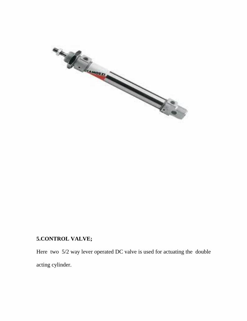

WORKING PRINCIPLE
WORKING PRINCIPLE
Before starting the operation of material handling system set the working
pressure to 5 bar from the compressor outlet Connect the 230 AC power
supply to the female electrical plug in order to supply the electrical power to
the relay control system and hence the solenoid valve direct the air supply
to the double acting cylinder The piston in the air cylinder reciprocate to
and fro
When the solenoid coil is ON the valve changed the direction of air to the
double acting cylinder Thus the valve reciprocates to and fro continuously
till power is cut off This reciprocate motion is converted to rotary motion
with help of ratchet wheel mechanism and the nylon belt moves over the
driving and driven pulley
The above arrangement can be modified to working as a
VIBRATOR by simply connecting the any other unit to the piston end
rod
INTRODUCTION TO
PNEUMATICS
INTRODUCTION TO PNEUMATICS
In engineering field may Machines make use of a fluid or compressed air to
develop a force to move or hold an object
A system which is operated by compressed air is known as Pneumatic
System It is most widely used the work Piece turning drilling sawing etc
By the use of Pneumatic System the risk of explosion on fire with
compressed air is minimum high working speed and simple in construction
PNEUMATIC COMPONENTS
In engineering field many machines make use of fluid for developing
a force to move or hold an object A number of fluid can be used in
devices and system Two commonly used fluids are oil and compressed
air A system which is operated by compressed air A system which is
operated by compressed air is know as pneumatic system
AIR COMPRESSOR
Compressor is a device which gets air fro the atmosphere and
compresses it for increasing the pressure of air Thus the compressed air
Thus the compressed air used for many application
The compression process requires work in put Hence a compressor is
driven by a prime mover Generally an electric motor is used as prime
mover The compressed air from compressor is stored in vessel called
reservoir Fro reservoir it be conveyed to the desired place through pipe
lines
2 FLTER
In pneumatic system an air filter is used to remove all foreign matter
An air filter dry clean air to flow without resistance various materials are
used for the filter element The air may be passed thorugh a piece metal a
pours stone felt resin impregnated paper In some filters centrifugal action
or cyclone action is used to remove foreign matters
3 PRESSURE REGULATOR
Constant pressure level is required for the trouble free operation of a
pneumatic control A pressure regulator is fitted downstream of the
compressed air filter It provides a constant set pressure at the outlet of the
outlet of the regulator The pressure regulator is also called as pressure
reducing valve or pressure regulating valve
4 LUBRICATOR
The purpose of an air lubricator is to provide the pneumatic
components with sufficient lubricant These lubricants must reduce the wear
of the moving parts reduce frictional forces and protect the equipment from
corrosion
Care should be taken to ensure that sufficient lubrication is provided
But excessive lubrication should be avoided
5 FLR Package (or) FRL Package
The air service unit is a combination of following units
1 Compressed air filter
2 Compressed air regulator
3 Compressed air lubricator
Air Filter regulator and lubricator are connected together with close
nipples as one package This unit is know as FLR (Filter regulator
lubricator)
6 PRESSURE CONTROL VALVE
Each hydraulic system is used to operate in a certain pressure range
Higher pressure causes damage of components To avoid this pressure
control valves are fitted in the circuits
7 Direction control valve
Directional control valves are used to control the direction of flow
The design principle is a major factor with regard to service life actuating
force switching times etc
8 Piston and Cylinder
single acting pneumatic cylinder
PNEUMATIC CITCUIT SYMBOL FOR SINGLE ACTING PNEUMATIC
CYLINDER
Pneumatic cylinders (sometimes known as air cylinders) are mechanical
devices which produce force often in combination with movement and are
powered by compressed gas (typically air)
To perform their function pneumatic cylinders impart a force by converting
the potential energy of compressed gas into kinetic energy This is achieved
by the compressed gas being able to expand without external energy input
which itself occurs due to the pressure gradient established by the
compressed gas being at a greater pressure than the atmospheric pressure
This air expansion forces a piston to move in the desired direction The
piston is a disc or cylinder and the piston rod transfers the force it develops
to the object to be moved
When selecting a pneumatic cylinder you must pay attention to
how far the piston extends when activated known as stroke
surface area of the piston face known as bore size
action type
pressure rating such as 50 PSI
type of connection to each port such as 14 NPT
must be rated for compressed air use
mounting method
Types
Although pneumatic cylinders will vary in appearance size and function
they generally fall into one of the specific categories shown below However
there are also numerous other types of pneumatic cylinder available many
of which are designed to fulfill specific and specialised functions
Single acting cylinders
Single acting cylinders (SAC) use the pressure imparted by compressed air
to create a driving force in one direction (usually out) and a spring to return
to the home position
Double acting cylinders
Double Acting Cylinders (DAC) use the force of air to move in both extend
and retract strokes They have two ports to allow air in one for outstroke
and one for instroke
Other types
Although SACs and DACs are the most common types of pneumatic
cylinder the following types are not particularly rare
Rotary air cylinders actuators that use air to impart a rotary motion
Rodless air cylinders These have no piston rod They are actuators
that use a mechanical or magnetic coupling to impart force typically
to a table or other body that moves along the length of the cylinder
body but does not extend beyond it
Sizes
Air cylinders are available in a variety of sizes and can typically range from
a small 25 mm air cylinder which might be used for picking up a small
transistor or other electronic component to 400 mm diameter air cylinders
which would impart enough force to lift a car Some pneumatic cylinders
reach 1000 mm in diameter and are used in place of hydraulic cylinders for
special circumstances where leaking hydraulic oil could impose an extreme
hazard
Pressure radius area and force relationships
Although the diameter of the piston and the force exerted by a cylinder are
related they are not directly proportional to one another Additionally the
typical mathematical relationship between the two assumes that the air
supply does not become saturated Due to the effective cross sectional area
reduced by the area of the piston rod the instroke force is less than the
outstroke force when both are powered pneumatically and by same supply of
compressed gas
The relationship between force on outstroke pressure and radius is as
follows
This is derived from the relationship between force pressure and effective
cross-sectional area which is
F = p A
With the same symbolic notation of variables as above but also A represents
the effective cross sectional area
On instroke the same relationship between force exerted pressure and
effective cross sectional area applies as discussed above for outstroke
However since the cross sectional area is less than the piston area the
relationship between force pressure and radius is different The calculation
isnt more complicated though since the effective cross sectional area is
merely that of the piston less that of the piston rod
For instroke therefore the relationship between force exerted pressure
radius of the piston and radius of the piston rod is as follows
Where
F represents the force exerted
r1 represents the radius of the piston
r2 represents the radius of the piston rod
π is pi approximately equal to 314159
VALVE CONNECTORS
POLYURETHANE TUBE shortly say PUN tube
Manual operations involving heavy lifting Pushing or pulling
motions can be firing for the operations and can induce a monotony which
results in lowered production Cylinders have been designed to carry out
these movements with a pre ndash determined force and stroke and can be fitted
to synchronize with operation cycles of many machines it is worth wile to
examine the existing plan and methods of movement and to consider the
numberous mechanical applications which the range of pneumatic cylinders
make possible Quality is to keynote of air cylinder Engineer them into
you production setup to get the last ounce of power speed and efficiency to
save time space and money
Piston is cylinder part which moves in a cylinder have corresponding
hole on it To make the strokes effective there is no gap between them or
with a very tiny gap part of the micron The cylinder and its piston have a
glazing surface where there is a contact between them for easy motion of
piston and avoiding wear and tear of both The outer side of the cylinder
have mountings consists of plate and studs attached with it But the of these
mountings the cylinder and piston assembly can fitted on any place of the
piston have threads on it for fastening theother parts (or) accessories
according the operating performed and the application required We can fit
holding devices Clamping materials or other metal cutting and forming
ports with which can be movable with the piston
Pneumatics are used practically in every industry for a wide variety of
manufacturing process pneumatics equipments are used for multiple
reasons The best reason is that it is air powered ordinary air turns out to be
very excellent as a fluid power components
Solenoid Valve
In order to automate the air flow in our system we have to provide an
electrically controlled valves Electrical devices can provide more effective
control less expensive interlocks having many additional safety features and
simplified automatic sequencing when a machine must operate in a
hazardous area remote actuation is a desirable The operator can provide
satisfactory control though electrical devices from a remote point with in a
safe area uding a semi automatic system and these electrical flow control
devices are also in use in full automation by providing proper action signals
Push and pull actuation can be priced b solenoids These movements
are used to open and close the pop pet type valves These actuations are
done according to the signals given to the solenoid coil when the decided by
the program The outlet of solenoiud coil when the decided by the program
The outlet of solenoid valve is connected to a spray gun which is going to
spray the paint
SOLENOID OPERATED VALVES
Solenoid valves are electromechanical devices like relays and
contractors A solenoid valve is used to obtain mechanical movement in
machinery by utilizing fluid or air pressure The fluid or air pressure is
applied to the cylinder piston through a valve operated by a cylindrical
electrical coil The electrical coil along with its frame and plunger is known
as the solenoid and the assembly of solenoid and mechanical valve is known
as solenoid valve The solenoid valve is thus another important
electromechanical device used in control of machines Solenoid valves are
of two types
1 Single solenoid spring return operating valve(52)
2 Double solenoid operating valve
In fig 1 is shown a single solenoid spring return valve in its de-energized
condition The symbol for the solenoid and the return are also shown The
solenoid valve is shown connected to the cylinder to help readers understand
the solenoid valve action In the de energized condition the plunger and the
valve spool position as shown in figure 1
52 WAY VALVE
In this position of spool port P is connected to port A and port B is
connected to tank or exhaust (ie atmosphere) if air is used Spring pressure
(S) keeps the spool in this condition as long as the coil is de energized
Fluid pressure from port P through port A is applied to the left side of the
cylinder piston Thus the cylinder piston moves in the right direction Now
when the solenoid coil is energized plunger is attracted and it pushes the
spool against spring pressure
The new position of plunger and spool are shown in fig 2
In this position of spool port A gets connected to tank and port P gets
connected to port B Thus pressure is applied to the cylinder piston from
right and moves the piston rod to the left At the same time fluid in the other
side is drained out to the tank When the solenoid coil is again de energized
the spring (S) will move the spool to its original position as shown in figure
1 Thus normally when the solenoid coil is de energized the piston rod
remains extended
PNEUMATIC
FITTING
PNEUMATIC FITTINGS
There are no nuts to tighten the tube to the fittings as in the
conventional type of metallic fittings The tube is connected to the
fitting by a simple push ensuring leak proof connection and can be
released by pressing the cap and does not require any special tooling
like spanner to connect (or) disconnect the tube from the fitting
SPECIFICATION OF THE FITTING
Body Material - Plastic
CollectThread Nipple - Brass
Seal - Nitrate Rubber
Fluid Used - Air
Max Operating Pressure - 7 Bar
Tolerance on OD of the tubes - 1 mm
Min Wall thickness of tubes - 1 mm
FLEXIBLE HOSES
The Pneumatic hoses which is used when pneumatic
components such as actuators are subjected to movement Hose is
fabricated in layer of
Elastomer or synthetic rubber which permits operation at high
pressure The standard outside diameter of tubing is 116 inch If the
hose is subjected to rubbing it should be encased in a protective
sleeve
ADVANTAGES AND LIMITATIONS
ADVANTAGES
The Pneumatic arm is more efficient in the technical field
Quick response is achieved
Simple in constructions
Easy to maintain and repair
Cost of the unit is less when compared to other robotics
No fire hazard problem due to over loading
Comparatively the operation cost is less
The operation of arm is faster because the media to operate is air
Continuous operation is possible without stopping
LIMITATIONS
High torque cannot be obtained
Load Carrying capacity of this unit is not very high (3 ndash 5 kgs)
Silencer may be used to reduce the noise of compressed air
APPLICATION
1) DISCHARGE OF WORKPIECE
The arm fed has wide application in low cost automation It can be
used in automated assembly lines to pick-up the finished product from
workstation and place them in the bins It can also be used to pick-up the
raw material and place them on the conveyor belts and vice versa
2) JOB CLAMPING
This unit can also be used in clamping operations in certain areas of
mass productions where clamping and unclamping have to be done at high
speeds The application of this unit is limited to operations which involves
moderate clamping forces
3) TRANSFER OF JOBS BETWEEN WORK STATIONS
The gripping method used in a low cost automation to move the work
piece from one workstation to another The combination of an angular
rotary motion is the principle behind this method The gripper holds the
work rigidly The to and fro motion is achieved by means of the actuating
cylinder
4) TOOL CHANGING APPLICATION
When the pneumatic arms are made smaller in size they can be used
in automatic tool changer in CNC turning and drilling machines by
attaching suitable tool holding device to the rotary cylinder
PNEUMATIC SPARE
PARTS DETAILS
PENUMATIC SPARE PARTS DETAITS
NAME OF THE PARTS SPECFICATION
1 Double acting cyclinder
( air max make )
2 single solenoid 52 way DCValve
3 ONOFF relay control
4 plywood board
5 Valve Connectors(5 Nos)
6 Plastic tube (5 metres)
7 pulley(two nos)
8ratchet wheel
9electrical plug
10nylon belt (40mmwidth)
20MM100MM
18 SIZE 24VDC
NO
12 MM 600450
18MM
6 x4 MM
40 mm
40mm
5amps230v ac
875mm
PNEUMATIC CIRCUIT
DIAGRAM
PNEUMATIC CIRCUIT DIAGRAM
ELECTRICAL
HARDWARE DETAILS
BLOCK DIAGRAM
12V
Power
supply
Interface
relay
START SWITCH
ONOFF
CONTROL
SOLENOID
VALVE
POWER SUPPLY UNIT
INTRODUCTION
All the electronic components starting from diode to Intel IC‟s only
work with a DC supply ranging from +5V to +12V We are utilizing for the
same the cheapest and commonly available energy source of 230V-50Hz
and stepping down rectifying filtering and regulating the voltage
STEP DOWN TRANSFORMER
When AC is applied to the primary winding of the power transformer
it can either be stepped down or stepped up depending on the value of DC
needed In our circuit the transformer of 230V12-0-12V is used to perform
the step down operation where a 230V AC appears as 24V AC across the
secondary winding Apart from stepping down voltages it gives isolation
between the power source and power supply circuitries
Power supply 24DC and 12v dc
A 24 ndash0 V step down transformer is used to step down 230V AC to
24V AC This 24V AC supply is converted to 24V DC using four rectifier
diodes The voltage from the rectifier section is regulated to 12V DC using
7812 IC This voltage is used for power supply for the ONOFF relay
control The power supply circuit is shown in fig
ELECTRICAL WIRING
DIAGRAM
M
P
N C
+ 24 V
PLC CONTACT
RELAY CIRCUIT
COST ESTIMATION
COST ESTIMATION
NAME OF THE PARTS PRICE
1 Double acting cyclinder 3 NOS
2 Single solenoid 52 way DCValve
3 Relay amp switch
4 MS STAND
5 Valve Connectors(5 Nosx 4000)
6 Plastic tube (2 metres)
7 CYLCLE wheel pulley(two nos)
8ratchet wheel
9electrical plug
10nylon belt (40mmwidth)
1152 WAY LEVER VALVE 2 NOS
TOTAL
400000
150000
150000
30000
30000
40000
20000
10000
40000
50000
160000
1080000
--------------------------------
CONCLUSION
CONCLUSION
We make this project entirely different from other projects Since
concepts involved in our project is entirely different that a single unit is used
to various purposes which is not developed by any of other team members
By doing this project we gained the knowledge of working of
pneumatic system and how automation can be effectively done with the help
of pneumatic system
It is concluded that any automation system can be done with the help
of electro pneumatic system
We have successfully completed the project work at our Institute
By doing this project work we understood the working principle and
uses of various valves switches relays etc
Once again we express our sincere thanks to our staff members
BIBILOGRAPHY
BIBILOGRAPHY
1 Low cost automation with pneumatics - FESTO
2 Electro pneumatics - FESTO
3 Hydraulics amp pneumatics for Power Production - Harry L ndash Stewart
4 Basic pneumatics - FESTO
5 wwwgooglecom
6 Workshop Technology - Hajra Chowdry
7 Production Technology -RS Khurmi
PHOTO VIEW

WORKING PRINCIPLE
Before starting the operation of material handling system set the working
pressure to 5 bar from the compressor outlet Connect the 230 AC power
supply to the female electrical plug in order to supply the electrical power to
the relay control system and hence the solenoid valve direct the air supply
to the double acting cylinder The piston in the air cylinder reciprocate to
and fro
When the solenoid coil is ON the valve changed the direction of air to the
double acting cylinder Thus the valve reciprocates to and fro continuously
till power is cut off This reciprocate motion is converted to rotary motion
with help of ratchet wheel mechanism and the nylon belt moves over the
driving and driven pulley
The above arrangement can be modified to working as a
VIBRATOR by simply connecting the any other unit to the piston end
rod
INTRODUCTION TO
PNEUMATICS
INTRODUCTION TO PNEUMATICS
In engineering field may Machines make use of a fluid or compressed air to
develop a force to move or hold an object
A system which is operated by compressed air is known as Pneumatic
System It is most widely used the work Piece turning drilling sawing etc
By the use of Pneumatic System the risk of explosion on fire with
compressed air is minimum high working speed and simple in construction
PNEUMATIC COMPONENTS
In engineering field many machines make use of fluid for developing
a force to move or hold an object A number of fluid can be used in
devices and system Two commonly used fluids are oil and compressed
air A system which is operated by compressed air A system which is
operated by compressed air is know as pneumatic system
AIR COMPRESSOR
Compressor is a device which gets air fro the atmosphere and
compresses it for increasing the pressure of air Thus the compressed air
Thus the compressed air used for many application
The compression process requires work in put Hence a compressor is
driven by a prime mover Generally an electric motor is used as prime
mover The compressed air from compressor is stored in vessel called
reservoir Fro reservoir it be conveyed to the desired place through pipe
lines
2 FLTER
In pneumatic system an air filter is used to remove all foreign matter
An air filter dry clean air to flow without resistance various materials are
used for the filter element The air may be passed thorugh a piece metal a
pours stone felt resin impregnated paper In some filters centrifugal action
or cyclone action is used to remove foreign matters
3 PRESSURE REGULATOR
Constant pressure level is required for the trouble free operation of a
pneumatic control A pressure regulator is fitted downstream of the
compressed air filter It provides a constant set pressure at the outlet of the
outlet of the regulator The pressure regulator is also called as pressure
reducing valve or pressure regulating valve
4 LUBRICATOR
The purpose of an air lubricator is to provide the pneumatic
components with sufficient lubricant These lubricants must reduce the wear
of the moving parts reduce frictional forces and protect the equipment from
corrosion
Care should be taken to ensure that sufficient lubrication is provided
But excessive lubrication should be avoided
5 FLR Package (or) FRL Package
The air service unit is a combination of following units
1 Compressed air filter
2 Compressed air regulator
3 Compressed air lubricator
Air Filter regulator and lubricator are connected together with close
nipples as one package This unit is know as FLR (Filter regulator
lubricator)
6 PRESSURE CONTROL VALVE
Each hydraulic system is used to operate in a certain pressure range
Higher pressure causes damage of components To avoid this pressure
control valves are fitted in the circuits
7 Direction control valve
Directional control valves are used to control the direction of flow
The design principle is a major factor with regard to service life actuating
force switching times etc
8 Piston and Cylinder
single acting pneumatic cylinder
PNEUMATIC CITCUIT SYMBOL FOR SINGLE ACTING PNEUMATIC
CYLINDER
Pneumatic cylinders (sometimes known as air cylinders) are mechanical
devices which produce force often in combination with movement and are
powered by compressed gas (typically air)
To perform their function pneumatic cylinders impart a force by converting
the potential energy of compressed gas into kinetic energy This is achieved
by the compressed gas being able to expand without external energy input
which itself occurs due to the pressure gradient established by the
compressed gas being at a greater pressure than the atmospheric pressure
This air expansion forces a piston to move in the desired direction The
piston is a disc or cylinder and the piston rod transfers the force it develops
to the object to be moved
When selecting a pneumatic cylinder you must pay attention to
how far the piston extends when activated known as stroke
surface area of the piston face known as bore size
action type
pressure rating such as 50 PSI
type of connection to each port such as 14 NPT
must be rated for compressed air use
mounting method
Types
Although pneumatic cylinders will vary in appearance size and function
they generally fall into one of the specific categories shown below However
there are also numerous other types of pneumatic cylinder available many
of which are designed to fulfill specific and specialised functions
Single acting cylinders
Single acting cylinders (SAC) use the pressure imparted by compressed air
to create a driving force in one direction (usually out) and a spring to return
to the home position
Double acting cylinders
Double Acting Cylinders (DAC) use the force of air to move in both extend
and retract strokes They have two ports to allow air in one for outstroke
and one for instroke
Other types
Although SACs and DACs are the most common types of pneumatic
cylinder the following types are not particularly rare
Rotary air cylinders actuators that use air to impart a rotary motion
Rodless air cylinders These have no piston rod They are actuators
that use a mechanical or magnetic coupling to impart force typically
to a table or other body that moves along the length of the cylinder
body but does not extend beyond it
Sizes
Air cylinders are available in a variety of sizes and can typically range from
a small 25 mm air cylinder which might be used for picking up a small
transistor or other electronic component to 400 mm diameter air cylinders
which would impart enough force to lift a car Some pneumatic cylinders
reach 1000 mm in diameter and are used in place of hydraulic cylinders for
special circumstances where leaking hydraulic oil could impose an extreme
hazard
Pressure radius area and force relationships
Although the diameter of the piston and the force exerted by a cylinder are
related they are not directly proportional to one another Additionally the
typical mathematical relationship between the two assumes that the air
supply does not become saturated Due to the effective cross sectional area
reduced by the area of the piston rod the instroke force is less than the
outstroke force when both are powered pneumatically and by same supply of
compressed gas
The relationship between force on outstroke pressure and radius is as
follows
This is derived from the relationship between force pressure and effective
cross-sectional area which is
F = p A
With the same symbolic notation of variables as above but also A represents
the effective cross sectional area
On instroke the same relationship between force exerted pressure and
effective cross sectional area applies as discussed above for outstroke
However since the cross sectional area is less than the piston area the
relationship between force pressure and radius is different The calculation
isnt more complicated though since the effective cross sectional area is
merely that of the piston less that of the piston rod
For instroke therefore the relationship between force exerted pressure
radius of the piston and radius of the piston rod is as follows
Where
F represents the force exerted
r1 represents the radius of the piston
r2 represents the radius of the piston rod
π is pi approximately equal to 314159
VALVE CONNECTORS
POLYURETHANE TUBE shortly say PUN tube
Manual operations involving heavy lifting Pushing or pulling
motions can be firing for the operations and can induce a monotony which
results in lowered production Cylinders have been designed to carry out
these movements with a pre ndash determined force and stroke and can be fitted
to synchronize with operation cycles of many machines it is worth wile to
examine the existing plan and methods of movement and to consider the
numberous mechanical applications which the range of pneumatic cylinders
make possible Quality is to keynote of air cylinder Engineer them into
you production setup to get the last ounce of power speed and efficiency to
save time space and money
Piston is cylinder part which moves in a cylinder have corresponding
hole on it To make the strokes effective there is no gap between them or
with a very tiny gap part of the micron The cylinder and its piston have a
glazing surface where there is a contact between them for easy motion of
piston and avoiding wear and tear of both The outer side of the cylinder
have mountings consists of plate and studs attached with it But the of these
mountings the cylinder and piston assembly can fitted on any place of the
piston have threads on it for fastening theother parts (or) accessories
according the operating performed and the application required We can fit
holding devices Clamping materials or other metal cutting and forming
ports with which can be movable with the piston
Pneumatics are used practically in every industry for a wide variety of
manufacturing process pneumatics equipments are used for multiple
reasons The best reason is that it is air powered ordinary air turns out to be
very excellent as a fluid power components
Solenoid Valve
In order to automate the air flow in our system we have to provide an
electrically controlled valves Electrical devices can provide more effective
control less expensive interlocks having many additional safety features and
simplified automatic sequencing when a machine must operate in a
hazardous area remote actuation is a desirable The operator can provide
satisfactory control though electrical devices from a remote point with in a
safe area uding a semi automatic system and these electrical flow control
devices are also in use in full automation by providing proper action signals
Push and pull actuation can be priced b solenoids These movements
are used to open and close the pop pet type valves These actuations are
done according to the signals given to the solenoid coil when the decided by
the program The outlet of solenoiud coil when the decided by the program
The outlet of solenoid valve is connected to a spray gun which is going to
spray the paint
SOLENOID OPERATED VALVES
Solenoid valves are electromechanical devices like relays and
contractors A solenoid valve is used to obtain mechanical movement in
machinery by utilizing fluid or air pressure The fluid or air pressure is
applied to the cylinder piston through a valve operated by a cylindrical
electrical coil The electrical coil along with its frame and plunger is known
as the solenoid and the assembly of solenoid and mechanical valve is known
as solenoid valve The solenoid valve is thus another important
electromechanical device used in control of machines Solenoid valves are
of two types
1 Single solenoid spring return operating valve(52)
2 Double solenoid operating valve
In fig 1 is shown a single solenoid spring return valve in its de-energized
condition The symbol for the solenoid and the return are also shown The
solenoid valve is shown connected to the cylinder to help readers understand
the solenoid valve action In the de energized condition the plunger and the
valve spool position as shown in figure 1
52 WAY VALVE
In this position of spool port P is connected to port A and port B is
connected to tank or exhaust (ie atmosphere) if air is used Spring pressure
(S) keeps the spool in this condition as long as the coil is de energized
Fluid pressure from port P through port A is applied to the left side of the
cylinder piston Thus the cylinder piston moves in the right direction Now
when the solenoid coil is energized plunger is attracted and it pushes the
spool against spring pressure
The new position of plunger and spool are shown in fig 2
In this position of spool port A gets connected to tank and port P gets
connected to port B Thus pressure is applied to the cylinder piston from
right and moves the piston rod to the left At the same time fluid in the other
side is drained out to the tank When the solenoid coil is again de energized
the spring (S) will move the spool to its original position as shown in figure
1 Thus normally when the solenoid coil is de energized the piston rod
remains extended
PNEUMATIC
FITTING
PNEUMATIC FITTINGS
There are no nuts to tighten the tube to the fittings as in the
conventional type of metallic fittings The tube is connected to the
fitting by a simple push ensuring leak proof connection and can be
released by pressing the cap and does not require any special tooling
like spanner to connect (or) disconnect the tube from the fitting
SPECIFICATION OF THE FITTING
Body Material - Plastic
CollectThread Nipple - Brass
Seal - Nitrate Rubber
Fluid Used - Air
Max Operating Pressure - 7 Bar
Tolerance on OD of the tubes - 1 mm
Min Wall thickness of tubes - 1 mm
FLEXIBLE HOSES
The Pneumatic hoses which is used when pneumatic
components such as actuators are subjected to movement Hose is
fabricated in layer of
Elastomer or synthetic rubber which permits operation at high
pressure The standard outside diameter of tubing is 116 inch If the
hose is subjected to rubbing it should be encased in a protective
sleeve
ADVANTAGES AND LIMITATIONS
ADVANTAGES
The Pneumatic arm is more efficient in the technical field
Quick response is achieved
Simple in constructions
Easy to maintain and repair
Cost of the unit is less when compared to other robotics
No fire hazard problem due to over loading
Comparatively the operation cost is less
The operation of arm is faster because the media to operate is air
Continuous operation is possible without stopping
LIMITATIONS
High torque cannot be obtained
Load Carrying capacity of this unit is not very high (3 ndash 5 kgs)
Silencer may be used to reduce the noise of compressed air
APPLICATION
1) DISCHARGE OF WORKPIECE
The arm fed has wide application in low cost automation It can be
used in automated assembly lines to pick-up the finished product from
workstation and place them in the bins It can also be used to pick-up the
raw material and place them on the conveyor belts and vice versa
2) JOB CLAMPING
This unit can also be used in clamping operations in certain areas of
mass productions where clamping and unclamping have to be done at high
speeds The application of this unit is limited to operations which involves
moderate clamping forces
3) TRANSFER OF JOBS BETWEEN WORK STATIONS
The gripping method used in a low cost automation to move the work
piece from one workstation to another The combination of an angular
rotary motion is the principle behind this method The gripper holds the
work rigidly The to and fro motion is achieved by means of the actuating
cylinder
4) TOOL CHANGING APPLICATION
When the pneumatic arms are made smaller in size they can be used
in automatic tool changer in CNC turning and drilling machines by
attaching suitable tool holding device to the rotary cylinder
PNEUMATIC SPARE
PARTS DETAILS
PENUMATIC SPARE PARTS DETAITS
NAME OF THE PARTS SPECFICATION
1 Double acting cyclinder
( air max make )
2 single solenoid 52 way DCValve
3 ONOFF relay control
4 plywood board
5 Valve Connectors(5 Nos)
6 Plastic tube (5 metres)
7 pulley(two nos)
8ratchet wheel
9electrical plug
10nylon belt (40mmwidth)
20MM100MM
18 SIZE 24VDC
NO
12 MM 600450
18MM
6 x4 MM
40 mm
40mm
5amps230v ac
875mm
PNEUMATIC CIRCUIT
DIAGRAM
PNEUMATIC CIRCUIT DIAGRAM
ELECTRICAL
HARDWARE DETAILS
BLOCK DIAGRAM
12V
Power
supply
Interface
relay
START SWITCH
ONOFF
CONTROL
SOLENOID
VALVE
POWER SUPPLY UNIT
INTRODUCTION
All the electronic components starting from diode to Intel IC‟s only
work with a DC supply ranging from +5V to +12V We are utilizing for the
same the cheapest and commonly available energy source of 230V-50Hz
and stepping down rectifying filtering and regulating the voltage
STEP DOWN TRANSFORMER
When AC is applied to the primary winding of the power transformer
it can either be stepped down or stepped up depending on the value of DC
needed In our circuit the transformer of 230V12-0-12V is used to perform
the step down operation where a 230V AC appears as 24V AC across the
secondary winding Apart from stepping down voltages it gives isolation
between the power source and power supply circuitries
Power supply 24DC and 12v dc
A 24 ndash0 V step down transformer is used to step down 230V AC to
24V AC This 24V AC supply is converted to 24V DC using four rectifier
diodes The voltage from the rectifier section is regulated to 12V DC using
7812 IC This voltage is used for power supply for the ONOFF relay
control The power supply circuit is shown in fig
ELECTRICAL WIRING
DIAGRAM
M
P
N C
+ 24 V
PLC CONTACT
RELAY CIRCUIT
COST ESTIMATION
COST ESTIMATION
NAME OF THE PARTS PRICE
1 Double acting cyclinder 3 NOS
2 Single solenoid 52 way DCValve
3 Relay amp switch
4 MS STAND
5 Valve Connectors(5 Nosx 4000)
6 Plastic tube (2 metres)
7 CYLCLE wheel pulley(two nos)
8ratchet wheel
9electrical plug
10nylon belt (40mmwidth)
1152 WAY LEVER VALVE 2 NOS
TOTAL
400000
150000
150000
30000
30000
40000
20000
10000
40000
50000
160000
1080000
--------------------------------
CONCLUSION
CONCLUSION
We make this project entirely different from other projects Since
concepts involved in our project is entirely different that a single unit is used
to various purposes which is not developed by any of other team members
By doing this project we gained the knowledge of working of
pneumatic system and how automation can be effectively done with the help
of pneumatic system
It is concluded that any automation system can be done with the help
of electro pneumatic system
We have successfully completed the project work at our Institute
By doing this project work we understood the working principle and
uses of various valves switches relays etc
Once again we express our sincere thanks to our staff members
BIBILOGRAPHY
BIBILOGRAPHY
1 Low cost automation with pneumatics - FESTO
2 Electro pneumatics - FESTO
3 Hydraulics amp pneumatics for Power Production - Harry L ndash Stewart
4 Basic pneumatics - FESTO
5 wwwgooglecom
6 Workshop Technology - Hajra Chowdry
7 Production Technology -RS Khurmi
PHOTO VIEW
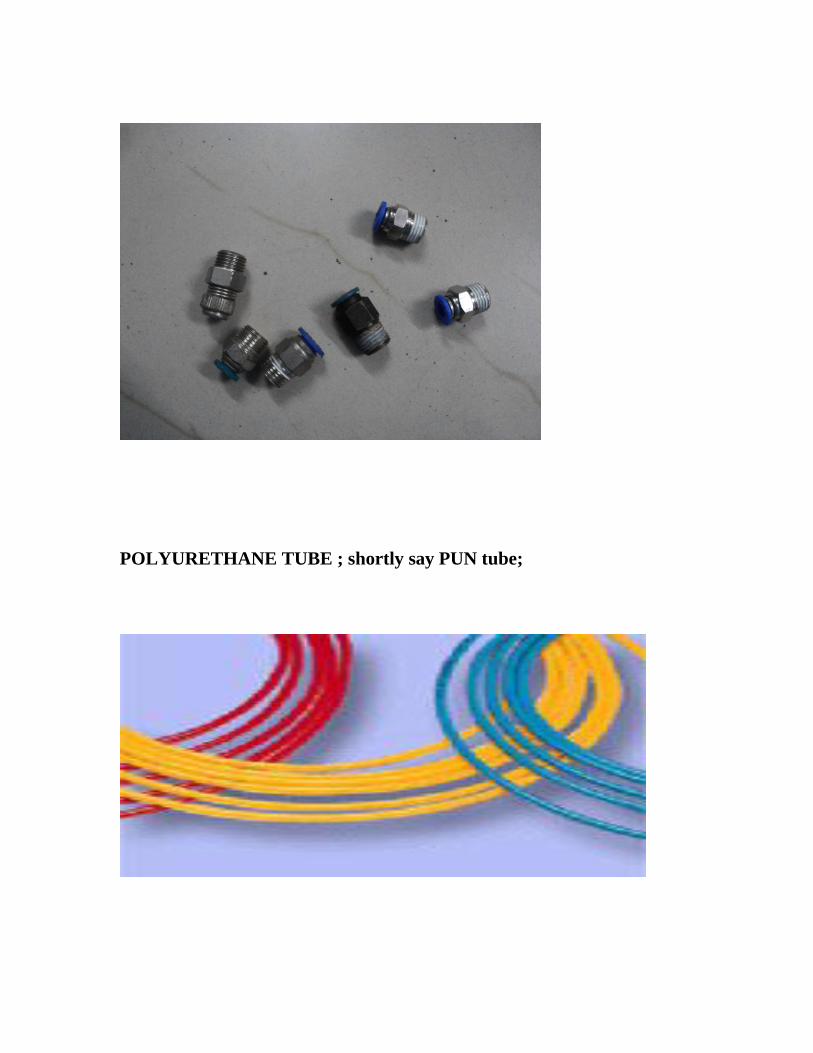
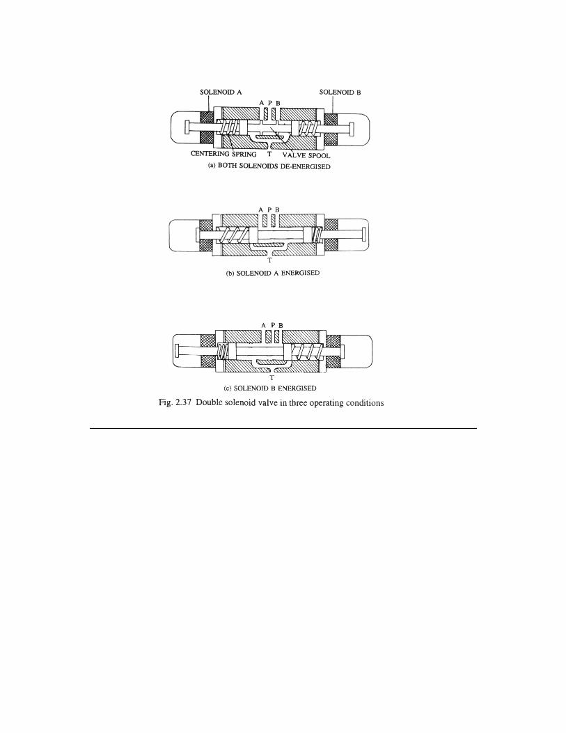
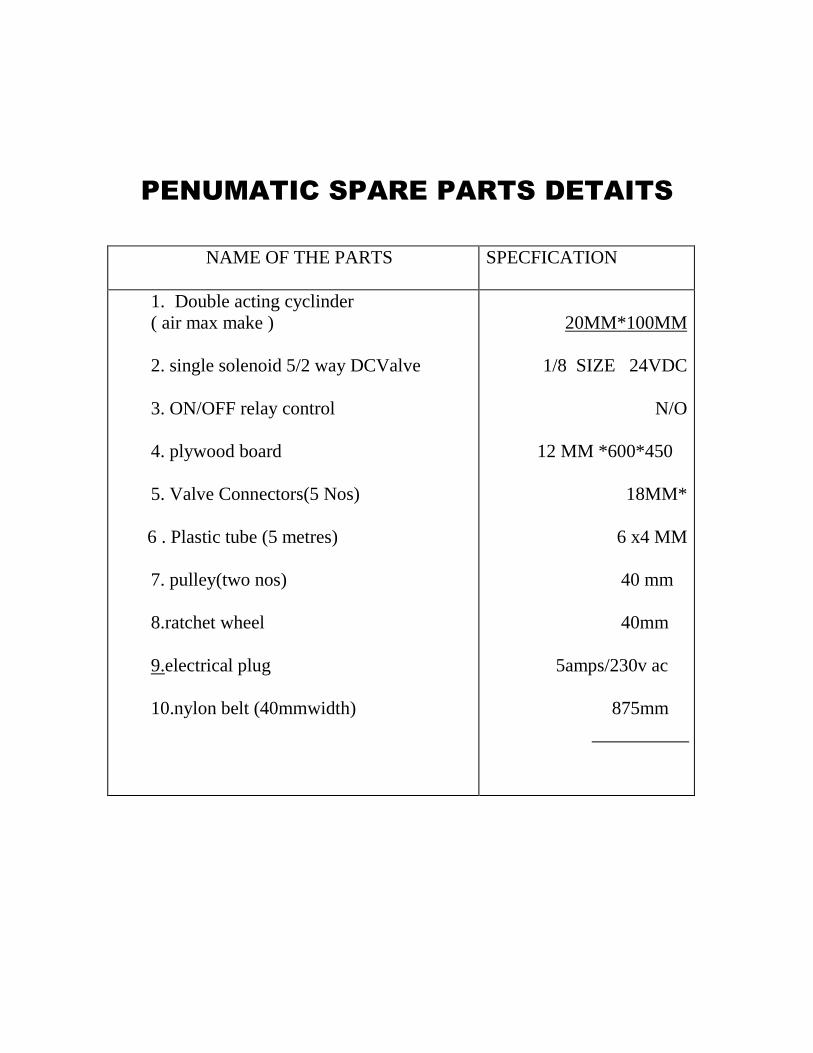

COST ESTIMATION
COST ESTIMATION
NAME OF THE PARTS PRICE
1 Double acting cyclinder 3 NOS
2 Single solenoid 52 way DCValve
3 Relay amp switch
4 MS STAND
5 Valve Connectors(5 Nosx 4000)
6 Plastic tube (2 metres)
7 CYLCLE wheel pulley(two nos)
8ratchet wheel
9electrical plug
10nylon belt (40mmwidth)
1152 WAY LEVER VALVE 2 NOS
TOTAL
400000
150000
150000
30000
30000
40000
20000
10000
40000
50000
160000
1080000
--------------------------------
CONCLUSION
CONCLUSION
We make this project entirely different from other projects Since
concepts involved in our project is entirely different that a single unit is used
to various purposes which is not developed by any of other team members
By doing this project we gained the knowledge of working of
pneumatic system and how automation can be effectively done with the help
of pneumatic system
It is concluded that any automation system can be done with the help
of electro pneumatic system
We have successfully completed the project work at our Institute
By doing this project work we understood the working principle and
uses of various valves switches relays etc
Once again we express our sincere thanks to our staff members
BIBILOGRAPHY
BIBILOGRAPHY
1 Low cost automation with pneumatics - FESTO
2 Electro pneumatics - FESTO
3 Hydraulics amp pneumatics for Power Production - Harry L ndash Stewart
4 Basic pneumatics - FESTO
5 wwwgooglecom
6 Workshop Technology - Hajra Chowdry
7 Production Technology -RS Khurmi
PHOTO VIEW

COST ESTIMATION
NAME OF THE PARTS PRICE
1 Double acting cyclinder 3 NOS
2 Single solenoid 52 way DCValve
3 Relay amp switch
4 MS STAND
5 Valve Connectors(5 Nosx 4000)
6 Plastic tube (2 metres)
7 CYLCLE wheel pulley(two nos)
8ratchet wheel
9electrical plug
10nylon belt (40mmwidth)
1152 WAY LEVER VALVE 2 NOS
TOTAL
400000
150000
150000
30000
30000
40000
20000
10000
40000
50000
160000
1080000
--------------------------------
CONCLUSION
CONCLUSION
We make this project entirely different from other projects Since
concepts involved in our project is entirely different that a single unit is used
to various purposes which is not developed by any of other team members
By doing this project we gained the knowledge of working of
pneumatic system and how automation can be effectively done with the help
of pneumatic system
It is concluded that any automation system can be done with the help
of electro pneumatic system
We have successfully completed the project work at our Institute
By doing this project work we understood the working principle and
uses of various valves switches relays etc
Once again we express our sincere thanks to our staff members
BIBILOGRAPHY
BIBILOGRAPHY
1 Low cost automation with pneumatics - FESTO
2 Electro pneumatics - FESTO
3 Hydraulics amp pneumatics for Power Production - Harry L ndash Stewart
4 Basic pneumatics - FESTO
5 wwwgooglecom
6 Workshop Technology - Hajra Chowdry
7 Production Technology -RS Khurmi
PHOTO VIEW

CONCLUSION
CONCLUSION
We make this project entirely different from other projects Since
concepts involved in our project is entirely different that a single unit is used
to various purposes which is not developed by any of other team members
By doing this project we gained the knowledge of working of
pneumatic system and how automation can be effectively done with the help
of pneumatic system
It is concluded that any automation system can be done with the help
of electro pneumatic system
We have successfully completed the project work at our Institute
By doing this project work we understood the working principle and
uses of various valves switches relays etc
Once again we express our sincere thanks to our staff members
BIBILOGRAPHY
BIBILOGRAPHY
1 Low cost automation with pneumatics - FESTO
2 Electro pneumatics - FESTO
3 Hydraulics amp pneumatics for Power Production - Harry L ndash Stewart
4 Basic pneumatics - FESTO
5 wwwgooglecom
6 Workshop Technology - Hajra Chowdry
7 Production Technology -RS Khurmi
PHOTO VIEW

CONCLUSION
We make this project entirely different from other projects Since
concepts involved in our project is entirely different that a single unit is used
to various purposes which is not developed by any of other team members
By doing this project we gained the knowledge of working of
pneumatic system and how automation can be effectively done with the help
of pneumatic system
It is concluded that any automation system can be done with the help
of electro pneumatic system
We have successfully completed the project work at our Institute
By doing this project work we understood the working principle and
uses of various valves switches relays etc
Once again we express our sincere thanks to our staff members
BIBILOGRAPHY
BIBILOGRAPHY
1 Low cost automation with pneumatics - FESTO
2 Electro pneumatics - FESTO
3 Hydraulics amp pneumatics for Power Production - Harry L ndash Stewart
4 Basic pneumatics - FESTO
5 wwwgooglecom
6 Workshop Technology - Hajra Chowdry
7 Production Technology -RS Khurmi
PHOTO VIEW

BIBILOGRAPHY
BIBILOGRAPHY
1 Low cost automation with pneumatics - FESTO
2 Electro pneumatics - FESTO
3 Hydraulics amp pneumatics for Power Production - Harry L ndash Stewart
4 Basic pneumatics - FESTO
5 wwwgooglecom
6 Workshop Technology - Hajra Chowdry
7 Production Technology -RS Khurmi
PHOTO VIEW

BIBILOGRAPHY
1 Low cost automation with pneumatics - FESTO
2 Electro pneumatics - FESTO
3 Hydraulics amp pneumatics for Power Production - Harry L ndash Stewart
4 Basic pneumatics - FESTO
5 wwwgooglecom
6 Workshop Technology - Hajra Chowdry
7 Production Technology -RS Khurmi
PHOTO VIEW

PHOTO VIEW