Embed Size (px)
Citation preview
Pneumatic conveying of wood powder by using a steam-jetejector
Salman Hassan*, KjellstroÈ m BjoÈ rn
Division of Energy Engineering, University of Technology, S-971 87 LuleaÊ, Sweden
Received 30 June 1999; accepted 17 April 2000
Abstract
Wood powder and sawdust are two fuels which will be tested in a pressurized cyclone-gasi®er. The gasi®er will bea part of combined cycle power plant where a gas turbine is run by the product gases from the gasi®er and a steam
boiler will use the exhaust gas from the turbine. To inject the fuel into the cyclone, a steam-jet ejector seems to beappropriate due to its simplicity and the possibility of using the steam produced by the boiler for feeding of the fuel.Three types of wood powder with di�erent particle-size distribution have been tested in di�erent ejector geometries.
The results show that the steam-jet ejector is suitable as a feeding pump for wood powder and sawdust. Forcommercial wood powder fuel with particle size below 1 mm, a powder to steam mass ¯ow ratio of about 25 andwith coarser sawdust a mass ¯ow ratio of at least 10 can be reached. The pressure gain required to overcome the
pressure drop in the cyclone gasi®er can be achieved. The relative pressure gain seems to be independent of the sizedistribution of the particles. 7 2000 Elsevier Science Ltd. All rights reserved.
Keywords: Wood powder; Steam-jet ejector; Cyclone gasi®er
1. Introduction
In 1994 a test facility for gasi®cation of wood-powder was designed and built by the Divisionof Energy Engineering at the LuleaÊ University ofTechnology. The facility is located at the labora-tory of Energy Technology Center in PiteaÊ , ETC.The aim of the work done at the facility is tostudy the possibilities to run a gas turbine in a
combined-cycle plant using product gas generatedfrom wood powder or sawdust in a cyclone gasi-®er as fuel. Feeding of the fuel into the cyclone isone of the problems studied. The feeding systemshould supply the amount of wood powderneeded at a uniform rate and in the same timegive the particles of the fuel a high inlet velocitywhich is necessary to get the maximum separ-ation of ash in the cyclone.
In previous papers [3,5] the authors togetherwith others have reported on the performance ofscrew-feeders. The ¯ow of the powder through
Biomass and Bioenergy 19 (2000) 103±117
0961-9534/00/$ - see front matter 7 2000 Elsevier Science Ltd. All rights reserved.
PII: S0961-9534(00 )00024-6
www.elsevier.com/locate/biombioe
* Correspondig author.
these feeders is somewhat irregular and the ¯uc-tuations can be very high at low loads. Gabra etal. suggested a solution where brushes are placedat the outlet from the screw-feeders while Jop-pich and Salman placed a vibrator feeder afterthe screw. Both these solutions reduced the ¯uc-tuations considerably.
In this paper the performance of a steam-jetejector used for injection of the wood powderand sawdust into the cyclone is examined.
2. The test facility
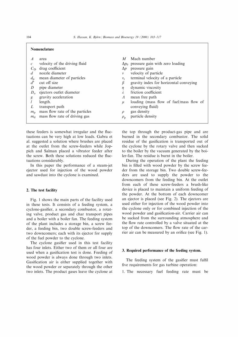
Fig. 1 shows the main parts of the facility usedin these tests. It consists of a feeding system, acyclone-gasi®er, a secondary combustor, a rotat-ing valve, product gas and char transport pipesand a boiler with a boiler fan. The feeding systemof the plant includes a storage bin, a screw fee-der, a feeding bin, two double screw-feeders andtwo downcomers; each with its ejector for supplyof the fuel powder to the cyclone.
The cyclone gasi®er used in this test facilityhas four inlets. Either two of them or all four areused when a gasi®cation test is done. Feeding ofwood powder is always done through two inlets.Gasi®cation air is either supplied together withthe wood powder or separately through the othertwo inlets. The product gases leave the cyclone at
the top through the product-gas pipe and areburned in the secondary combustor. The solidresidue of the gasi®cation is transported out ofthe cyclone by the rotary valve and then suckedto the boiler by the vacuum generated by the boi-ler-fan. The residue is burnt in the boiler.
During the operation of the plant the feedingbin is ®lled with wood powder by the screw fee-der from the storage bin. Two double screw-fee-ders are used to supply the powder to thedowncomers from the feeding bin. At the outletfrom each of these screw-feeders a brush-likedevice is placed to maintain a uniform feeding ofthe powder. At the bottom of each downcomeran ejector is placed (see Fig. 2). The ejectors areused either for injection of the wood powder intothe cyclone only or for combined injection of thewood powder and gasi®cation-air. Carrier air canbe sucked from the surrounding atmosphere andthe ¯ow rate controlled by a valve situated at thetop of the downcomers. The ¯ow rate of the car-rier air can be measured by an ori®ce (see Fig. 1).
3. Required performance of the feeding system.
The feeding system of the gasi®er must ful®l®ve requirements for gas turbine operation:
1. The necessary fuel feeding rate must be
Nomenclature
A areac velocity of the driving ¯uidCD drag coe�cientd nozzle diameterdp mean diameter of particlesd� cut o� sizeD pipe diameterDo ejectors outlet diameterg gravity accelerationl length.L transport pathmp mass ¯ow rate of the particlesmd mass ¯ow rate of driving gas
M Mach numberDp0 pressure gain with zero loadingDp pressure gainv velocity of particlevt terminal velocity of a particleb gravity index for horizontal conveyingZ dynamic viscosityl friction coe�cientL mean free pathm loading (mass ¯ow of fuel/mass ¯ow of
conveying ¯uid)r gas densityrp particle density
S. Hassan, K. BjoÈrn / Biomass and Bioenergy 19 (2000) 103±117104
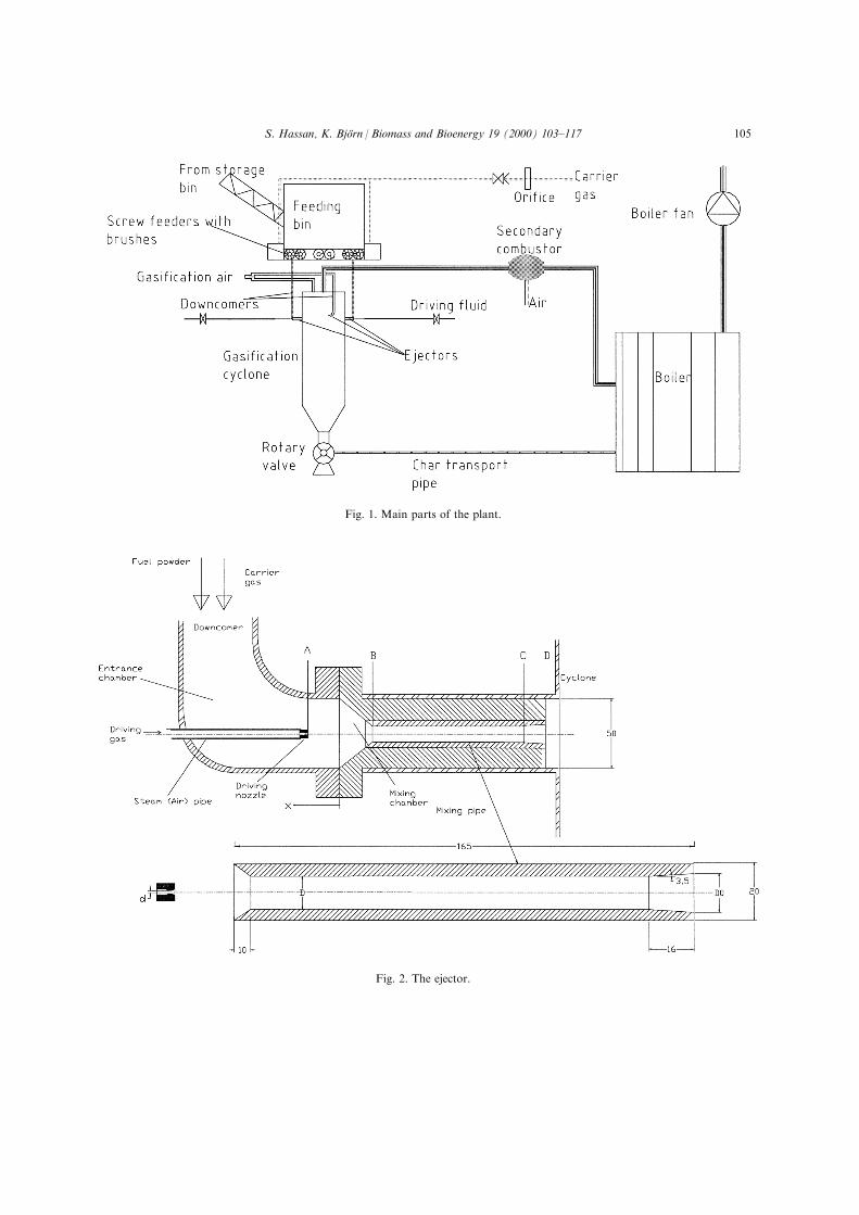
Fig. 1. Main parts of the plant.
Fig. 2. The ejector.
S. Hassan, K. BjoÈrn / Biomass and Bioenergy 19 (2000) 103±117 105
achieved.
2. Fluctuations of the fuel feeding rate must be
small (+/ÿ 10%) [2].
3. The feeding of the fuel must be achieved with
minimum ¯ow of driving gas and carrier gas
(highest loading possible).
4. The fuel must enter the gasi®er with high vel-
ocity.
5. The feeding system shall give a pressure gain
exceeding the pressure losses in the cyclone.
The gas turbine to be operated by the gasi-
®er in the facility will require a fuel feeding
rate of about 100 kg/h. Since there are two
fuel ejectors, each ejector has to inject at least
50 kg/h.
There is a risk for dust-explosion if a mix-
ture of wood powder and air has a concen-
tration of oxygen above 8% at atmospheric
pressure and 9% at 5 bar [9]. Inertization of
the feeding bin and the downcomers is there-
fore desirable. To avoid a large consumption
of inert gas, the carrier gas ¯owing with the
wood powder must be minimized. If possible,
the injection of the powder shall be done
without any ¯ow of carrier gas.
It is also desirable to minimize the need for
driving gas ¯ow, since the driving gas must be
pressurised. When steam is used, the driving
gas also adds to the ¯ow of inert gases into
the cyclone.
One of the aims of the cyclone gasi®er is to
achieve e�cient separation of particles. The
inlet velocity of the powder particles therefore
needs to be high since this will reduce the cut-
o� size of the cyclone gasi®er [6].
There is a pressure drop of 100±300 Pa in
the cyclone gasi®er depending on the geometry
of its outlet pipe. This pressure drop must be
gained by the feeding system. The ejectors act
as a pump which give the pressure gain
required to overcome these pressure losses.
Some of these requirements are contradictory
such as the requirement of high inlet velocity of
particles against the minimizing of the driving
¯uid. The velocity of the fuel depends on the
momentum of the driving ¯uid. Therefore a bal-
ance between these requirements is a challengefor the designer.
4. The ejector
The ejector used is shown in Fig. 2 The nozzlefor the driving ¯uid is a convergent±divergentnozzle with a throat diameter of 1.2 mm giving asupersonic outlet velocity (about M � 1:6). Theposition of the outlet of the driving nozzle couldbe varied relative to the mixing chamber.
The mixing pipe has a short convergententrance, a relative long mixing section of con-stant diameter and a short divergent exit. Threediameters of the mixing pipe i.e. 12, 14 and 16mm were tested, giving ratios between the drivingnozzle throat diameter and mixing section diam-eter of 10, 11.67 and 13.3, respectively. The cor-responding outlet diameters Do were 16, 20, and20 mm.
5. Characteristics of fuel powders
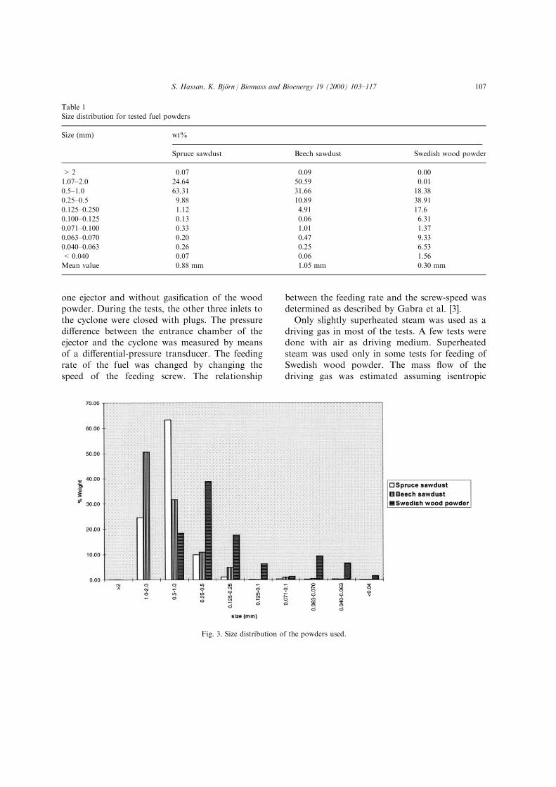
The three fuel powders tested were Swedishcommercial wood powder fuel produced bygrinding of pine and ®r, sawdust from beech andsawdust from spruce. The bulk density for thewood powder is 210 kg/m3, for the saw dust ofspruce 159 kg/m3and for sawdust of beech 306kg/m3. The size distributions of particles weredetermined by sieving and are shown in theTable 1 and Fig. 3. The mean size given in thetable is the mass weighted mean size dp:
dp �X
mpidiXmpi
�1�
Where mpi is the mass-percentage of each fractionof powder of average size di:
6. Experimental
All the experiments reported here were done atatmospheric pressure in the downcomers with
S. Hassan, K. BjoÈrn / Biomass and Bioenergy 19 (2000) 103±117106
one ejector and without gasi®cation of the woodpowder. During the tests, the other three inlets tothe cyclone were closed with plugs. The pressuredi�erence between the entrance chamber of theejector and the cyclone was measured by meansof a di�erential-pressure transducer. The feedingrate of the fuel was changed by changing thespeed of the feeding screw. The relationship
between the feeding rate and the screw-speed wasdetermined as described by Gabra et al. [3].
Only slightly superheated steam was used as adriving gas in most of the tests. A few tests weredone with air as driving medium. Superheatedsteam was used only in some tests for feeding ofSwedish wood powder. The mass ¯ow of thedriving gas was estimated assuming isentropic
Table 1
Size distribution for tested fuel powders
Size (mm) wt%
Spruce sawdust Beech sawdust Swedish wood powder
> 2 0.07 0.09 0.00
1.07±2.0 24.64 50.59 0.01
0.5±1.0 63.31 31.66 18.38
0.25±0.5 9.88 10.89 38.91
0.125±0.250 1.12 4.91 17.6
0.100±0.125 0.13 0.06 6.31
0.071±0.100 0.33 1.01 1.37
0.063±0.070 0.20 0.47 9.33
0.040±0.063 0.26 0.25 6.53
< 0.040 0.07 0.06 1.56
Mean value 0.88 mm 1.05 mm 0.30 mm
Fig. 3. Size distribution of the powders used.
S. Hassan, K. BjoÈrn / Biomass and Bioenergy 19 (2000) 103±117 107
critical ¯ow in the driving gas nozzle. Table 2shows the condition and ¯ow rates of the drivingmedium for the ejector.
The loading, de®ned as the ratio between the¯ow rate of the powder conveyed to the mass¯ow of the driving gas:
m � _mp
_md
�2�
could be changed by increasing the ¯ow rate ofthe powder i.e. by increasing the speed of the fee-der screws.
Tests were made with di�erent diameters ofthe mixing pipe of the ejector (12, 14 and 16mm).
The powder, which is injected into the cyclone,was discharged from the cyclone by the rotaryvalve and then sucked to the boiler by the vac-uum produced by the boiler fan.
One test was made to examine the e�ect of thedriving nozzle position. In this test, the positionof the outlet of the nozzle relative to the entranceof the ejector was changed see Fig. 2 and themass ¯ow of air sucked measured. This test wasdone without injection of any wood powder.
All the measurements were recorded at a fre-quency of 0.5 Hz.
7. Results
7.1. E�ect of the driving nozzle position
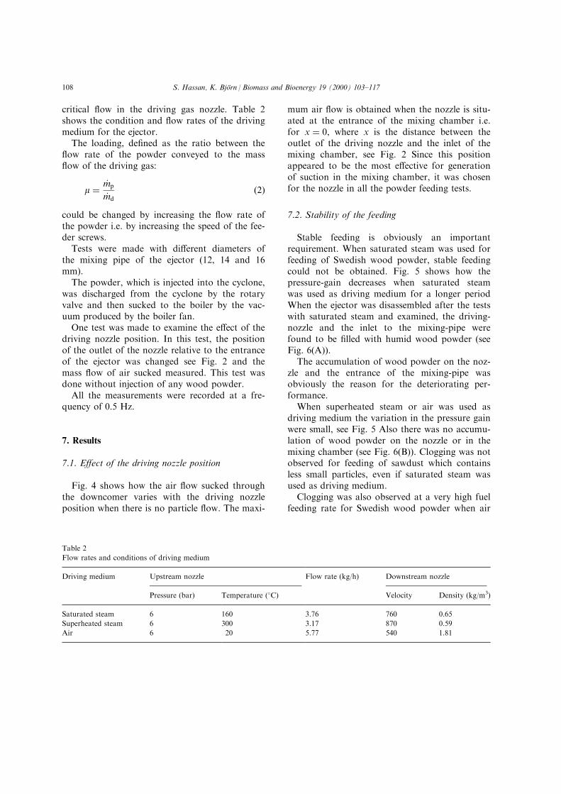
Fig. 4 shows how the air ¯ow sucked throughthe downcomer varies with the driving nozzleposition when there is no particle ¯ow. The maxi-
mum air ¯ow is obtained when the nozzle is situ-ated at the entrance of the mixing chamber i.e.for x � 0, where x is the distance between theoutlet of the driving nozzle and the inlet of themixing chamber, see Fig. 2 Since this positionappeared to be the most e�ective for generationof suction in the mixing chamber, it was chosenfor the nozzle in all the powder feeding tests.
7.2. Stability of the feeding
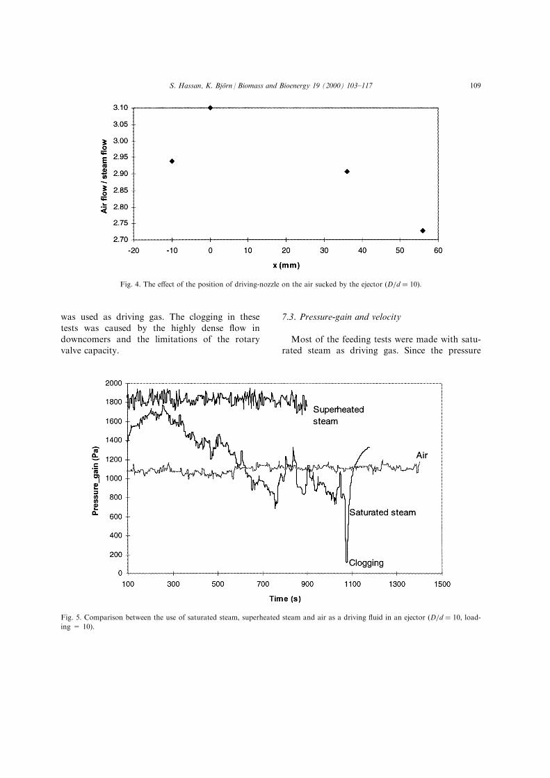
Stable feeding is obviously an importantrequirement. When saturated steam was used forfeeding of Swedish wood powder, stable feedingcould not be obtained. Fig. 5 shows how thepressure-gain decreases when saturated steamwas used as driving medium for a longer periodWhen the ejector was disassembled after the testswith saturated steam and examined, the driving-nozzle and the inlet to the mixing-pipe werefound to be ®lled with humid wood powder (seeFig. 6(A)).
The accumulation of wood powder on the noz-zle and the entrance of the mixing-pipe wasobviously the reason for the deteriorating per-formance.
When superheated steam or air was used asdriving medium the variation in the pressure gainwere small, see Fig. 5 Also there was no accumu-lation of wood powder on the nozzle or in themixing chamber (see Fig. 6(B)). Clogging was notobserved for feeding of sawdust which containsless small particles, even if saturated steam wasused as driving medium.
Clogging was also observed at a very high fuelfeeding rate for Swedish wood powder when air
Table 2
Flow rates and conditions of driving medium
Driving medium Upstream nozzle Flow rate (kg/h) Downstream nozzle
Pressure (bar) Temperature (8C) Velocity Density (kg/m3)
Saturated steam 6 160 3.76 760 0.65
Superheated steam 6 300 3.17 870 0.59
Air 6 20 5.77 540 1.81
S. Hassan, K. BjoÈrn / Biomass and Bioenergy 19 (2000) 103±117108
was used as driving gas. The clogging in thesetests was caused by the highly dense ¯ow indowncomers and the limitations of the rotaryvalve capacity.
7.3. Pressure-gain and velocity
Most of the feeding tests were made with satu-rated steam as driving gas. Since the pressure
Fig. 4. The e�ect of the position of driving-nozzle on the air sucked by the ejector �D=d � 10�:
Fig. 5. Comparison between the use of saturated steam, superheated steam and air as a driving ¯uid in an ejector �D=d � 10, load-
ing = 10).
S. Hassan, K. BjoÈrn / Biomass and Bioenergy 19 (2000) 103±117 109
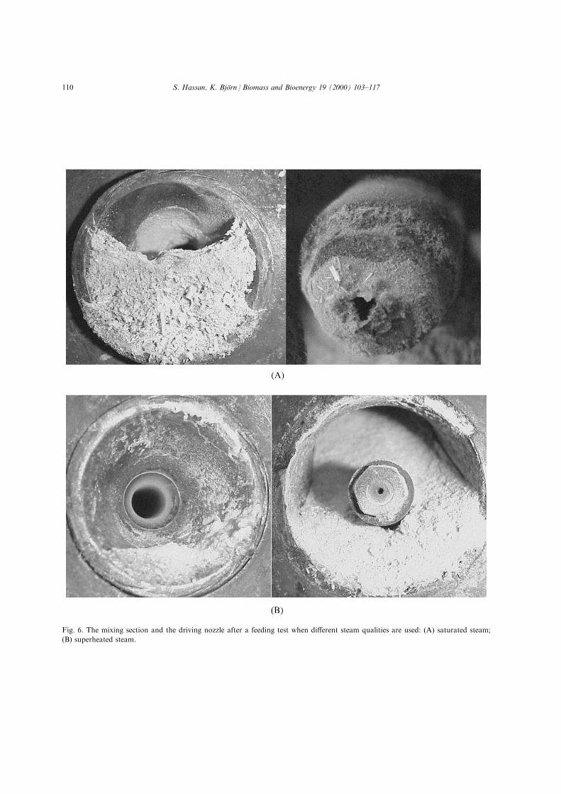
Fig. 6. The mixing section and the driving nozzle after a feeding test when di�erent steam qualities are used: (A) saturated steam;
(B) superheated steam.
S. Hassan, K. BjoÈrn / Biomass and Bioenergy 19 (2000) 103±117110
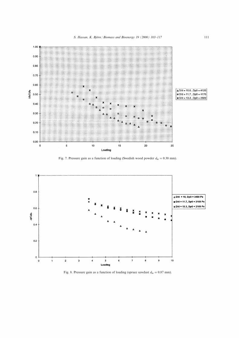
Fig. 7. Pressure gain as a function of loading (Swedish wood powder dm � 0:30 mm).
Fig. 8. Pressure gain as a function of loading (spruce sawdust dm � 0:87 mm).
S. Hassan, K. BjoÈrn / Biomass and Bioenergy 19 (2000) 103±117 111
gain varied in the tests with Swedish wood pow-der, the pressure gain for undisturbed feedingwas determined as the average value during 60,30 s after the start of the test. Figs. 7±9 show themeasured pressure gain as a function of the load-ing.
The results for Swedish wood powder areshown in Fig. 7. A maximum loading of 24.8 wasreached. As seen from Fig. 7 the pressure-gaindecreases as the loading increases.
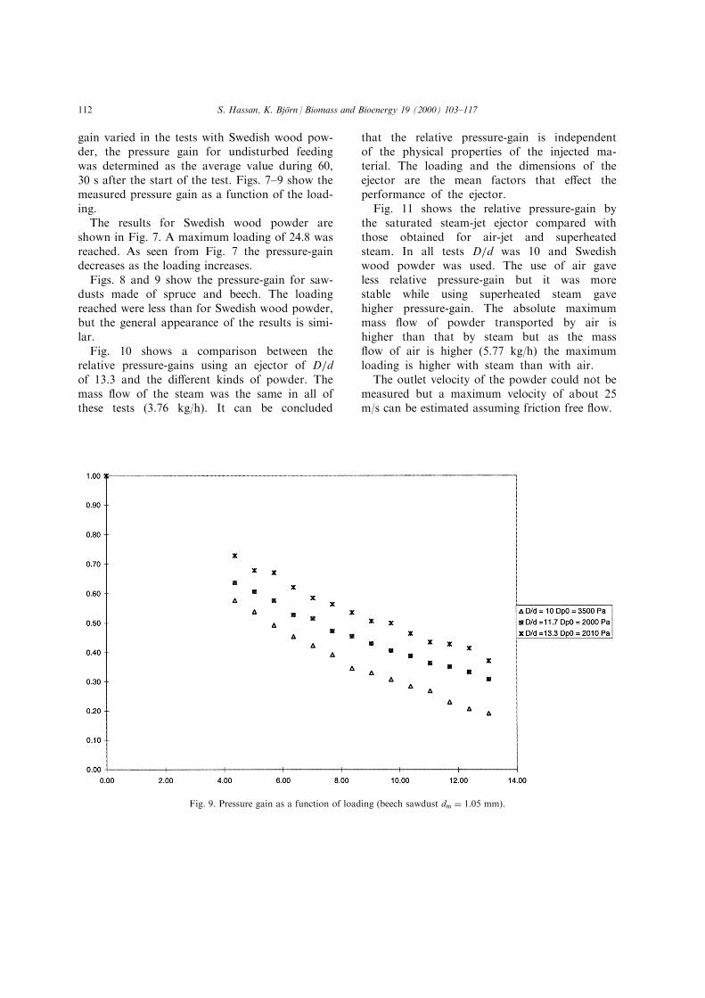
Figs. 8 and 9 show the pressure-gain for saw-dusts made of spruce and beech. The loadingreached were less than for Swedish wood powder,but the general appearance of the results is simi-lar.
Fig. 10 shows a comparison between therelative pressure-gains using an ejector of D=dof 13.3 and the di�erent kinds of powder. Themass ¯ow of the steam was the same in all ofthese tests (3.76 kg/h). It can be concluded
that the relative pressure-gain is independentof the physical properties of the injected ma-terial. The loading and the dimensions of theejector are the mean factors that e�ect theperformance of the ejector.
Fig. 11 shows the relative pressure-gain bythe saturated steam-jet ejector compared withthose obtained for air-jet and superheatedsteam. In all tests D=d was 10 and Swedishwood powder was used. The use of air gaveless relative pressure-gain but it was morestable while using superheated steam gavehigher pressure-gain. The absolute maximummass ¯ow of powder transported by air ishigher than that by steam but as the mass¯ow of air is higher (5.77 kg/h) the maximumloading is higher with steam than with air.
The outlet velocity of the powder could not bemeasured but a maximum velocity of about 25m/s can be estimated assuming friction free ¯ow.
Fig. 9. Pressure gain as a function of loading (beech sawdust dm � 1:05 mm).
S. Hassan, K. BjoÈrn / Biomass and Bioenergy 19 (2000) 103±117112
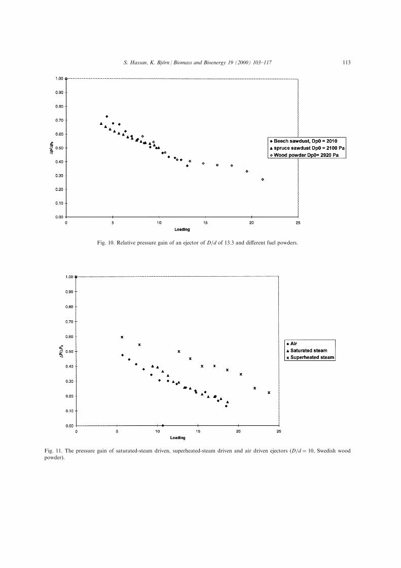
Fig. 10. Relative pressure gain of an ejector of D=d of 13.3 and di�erent fuel powders.
Fig. 11. The pressure gain of saturated-steam driven, superheated-steam driven and air driven ejectors �D=d � 10, Swedish wood
powder).
S. Hassan, K. BjoÈrn / Biomass and Bioenergy 19 (2000) 103±117 113
8. Theoretical considerations
8.1. Theoretical model proposed by Bohnet
A mathematical model for the calculation ofthe particle velocity and the pressure-gain by theejector has been developed by Bohnet [1]. Hedivided the ejector into three di�erent zones; thehopper (mixing chamber), the mixing tube andthe di�user. In both the hopper and the mixingtube the driven ¯ow (particles) is acceleratedwhile in the di�user the particles are acceleratedonly if the particles have not been accelerated totheir ®nal velocity after the mixing tube.
Bohnet suggested that the average velocity ofthe driving gas in each of the three zones is cal-culated from the continuity equation and simplegeometrical considerations. The retardation ofthe driving gas caused by the acceleration of theparticle is ignored.
For each section the acceleration of the par-ticles is then calculated by considering the dragforce (FD) between the particles and the drivinggas, friction force (Ff ) between the particles andthe wall and the gravity force (FG), required tokeep the particles suspended in the gas:
mpdv
dt� FD ÿ Ff ÿ FG �3�
The drag force is expressed in terms of the term-inal velocity vt of the particles which gives theacceleration as
dv
dt� g
�cÿ v
vt
�2
ÿl v2
2dÿ bg �4�
Where l is a friction factor with a value of0.002±0.005 and b is a factor suggested by Rizk[8]. For particles transported horizontally, Boh-net put this factor to a constant of 0.4 whileRizk recommended that b is calculated as theratio between the terminal velocity of the par-ticles and the velocity of the driving jet. Whenthe drag coe�cient CD is known, the terminalvelocity can be calculated from
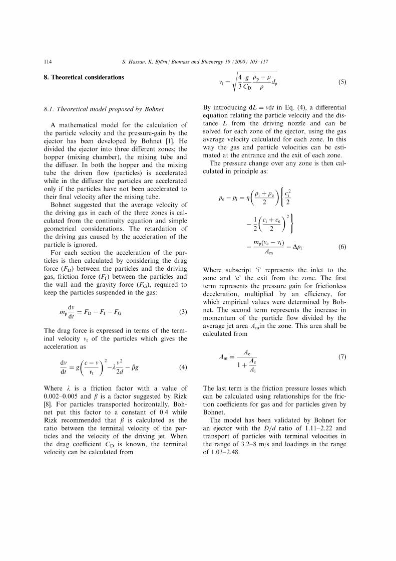
vt ������������������������������4
3
g
CD
rp ÿ r
rdp
s�5�
By introducing dL � vdt in Eq. (4), a di�erentialequation relating the particle velocity and the dis-tance L from the driving nozzle and can besolved for each zone of the ejector, using the gasaverage velocity calculated for each zone. In thisway the gas and particle velocities can be esti-mated at the entrance and the exit of each zone.
The pressure change over any zone is then cal-culated in principle as:
pe ÿ pi � Z�ri � re
2
�(c2i2
ÿ 1
2
�ci � ce
2
�2)
ÿ mp�ve ÿ vi �Am
ÿ Dpf �6�
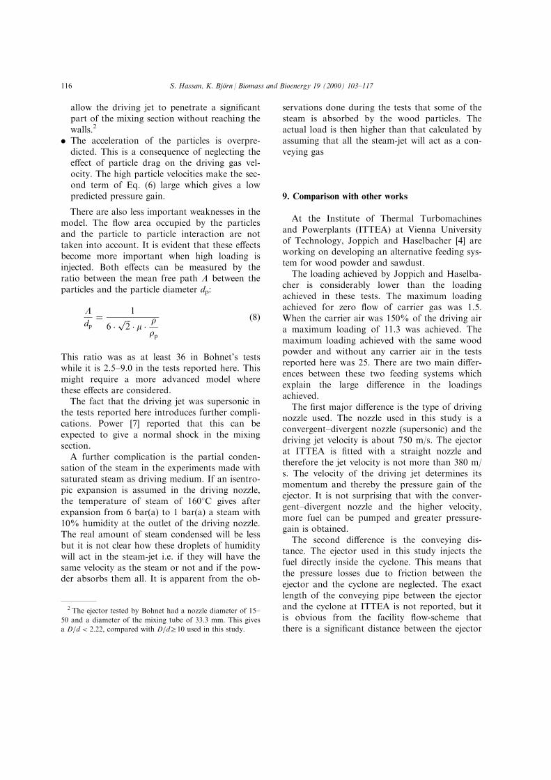
Where subscript `i' represents the inlet to thezone and `e' the exit from the zone. The ®rstterm represents the pressure gain for frictionlessdeceleration, multiplied by an e�ciency, forwhich empirical values were determined by Boh-net. The second term represents the increase inmomentum of the particle ¯ow divided by theaverage jet area Amin the zone. This area shall becalculated from
Am � Ae
1� Ae
Ai
�7�
The last term is the friction pressure losses whichcan be calculated using relationships for the fric-tion coe�cients for gas and for particles given byBohnet.
The model has been validated by Bohnet foran ejector with the D=d ratio of 1.11±2.22 andtransport of particles with terminal velocities inthe range of 3.2±8 m/s and loadings in the rangeof 1.03±2.48.
S. Hassan, K. BjoÈrn / Biomass and Bioenergy 19 (2000) 103±117114
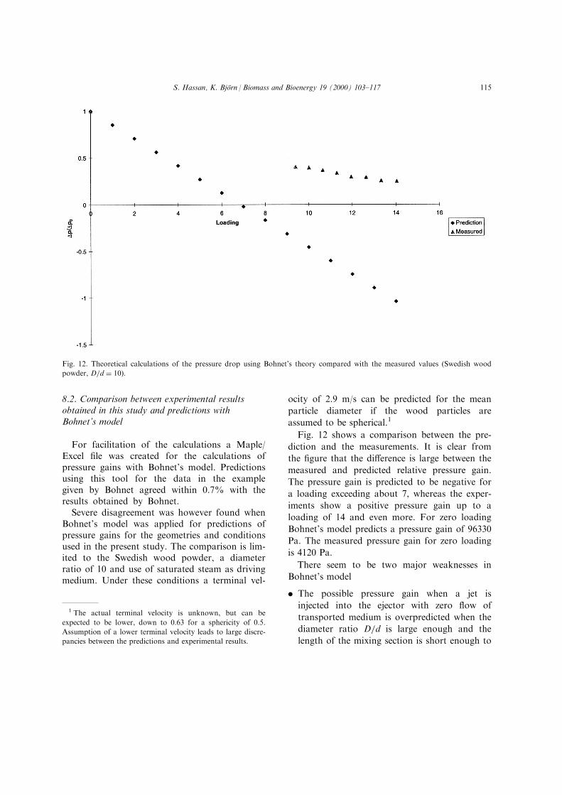
8.2. Comparison between experimental resultsobtained in this study and predictions withBohnet's model
For facilitation of the calculations a Maple/Excel ®le was created for the calculations ofpressure gains with Bohnet's model. Predictionsusing this tool for the data in the examplegiven by Bohnet agreed within 0.7% with theresults obtained by Bohnet.
Severe disagreement was however found whenBohnet's model was applied for predictions ofpressure gains for the geometries and conditionsused in the present study. The comparison is lim-ited to the Swedish wood powder, a diameterratio of 10 and use of saturated steam as drivingmedium. Under these conditions a terminal vel-
ocity of 2.9 m/s can be predicted for the mean
particle diameter if the wood particles are
assumed to be spherical.1
Fig. 12 shows a comparison between the pre-
diction and the measurements. It is clear from
the ®gure that the di�erence is large between the
measured and predicted relative pressure gain.
The pressure gain is predicted to be negative for
a loading exceeding about 7, whereas the exper-
iments show a positive pressure gain up to a
loading of 14 and even more. For zero loading
Bohnet's model predicts a pressure gain of 96330
Pa. The measured pressure gain for zero loading
is 4120 Pa.
There seem to be two major weaknesses in
Bohnet's model
. The possible pressure gain when a jet is
injected into the ejector with zero ¯ow of
transported medium is overpredicted when the
diameter ratio D=d is large enough and the
length of the mixing section is short enough to
Fig. 12. Theoretical calculations of the pressure drop using Bohnet's theory compared with the measured values (Swedish wood
powder, D=d � 10).
1 The actual terminal velocity is unknown, but can be
expected to be lower, down to 0.63 for a sphericity of 0.5.
Assumption of a lower terminal velocity leads to large discre-
pancies between the predictions and experimental results.
S. Hassan, K. BjoÈrn / Biomass and Bioenergy 19 (2000) 103±117 115
allow the driving jet to penetrate a signi®cantpart of the mixing section without reaching thewalls.2
. The acceleration of the particles is overpre-dicted. This is a consequence of neglecting thee�ect of particle drag on the driving gas vel-ocity. The high particle velocities make the sec-ond term of Eq. (6) large which gives a lowpredicted pressure gain.
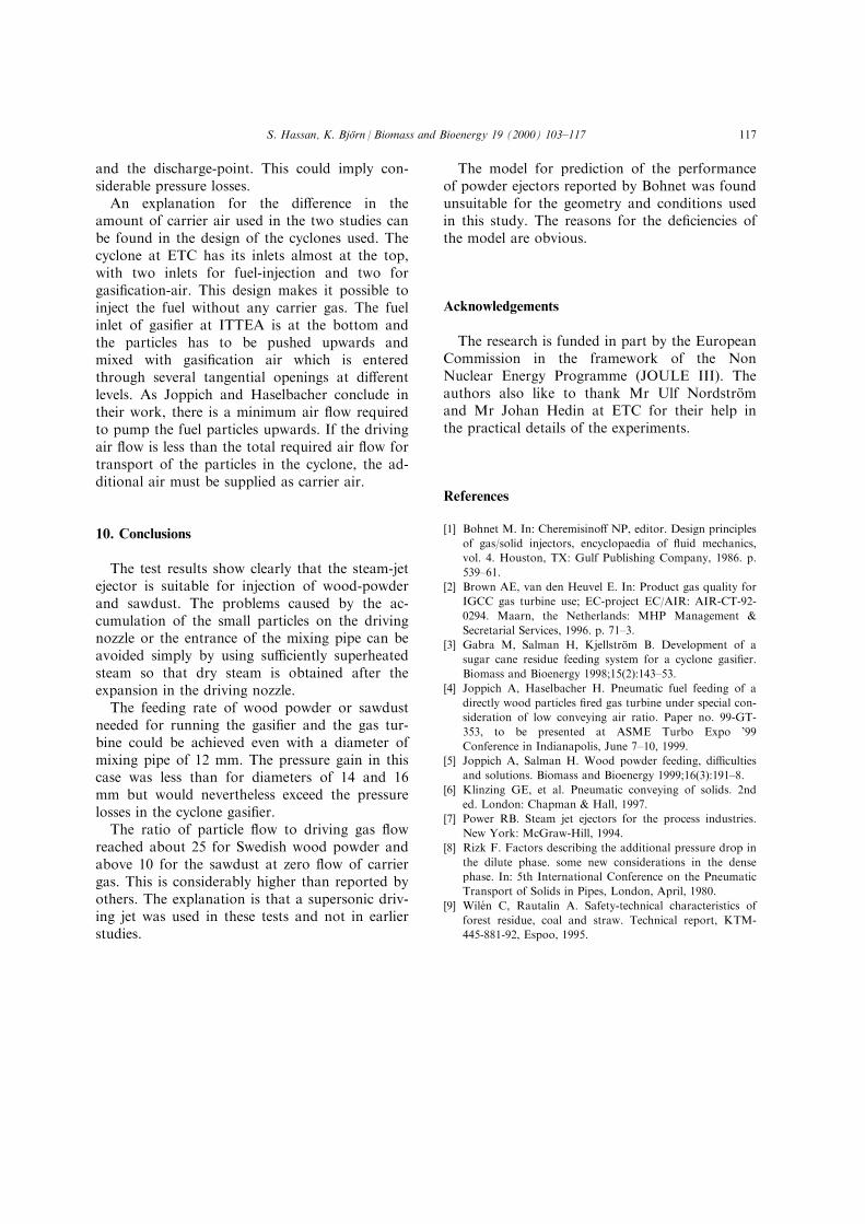
There are also less important weaknesses in themodel. The ¯ow area occupied by the particlesand the particle to particle interaction are nottaken into account. It is evident that these e�ectsbecome more important when high loading isinjected. Both e�ects can be measured by theratio between the mean free path L between theparticles and the particle diameter dp:
Ldp
� 1
6 � ���2p � m � r
rp
�8�
This ratio was as at least 36 in Bohnet's testswhile it is 2.5±9.0 in the tests reported here. Thismight require a more advanced model wherethese e�ects are considered.
The fact that the driving jet was supersonic inthe tests reported here introduces further compli-cations. Power [7] reported that this can beexpected to give a normal shock in the mixingsection.
A further complication is the partial conden-sation of the steam in the experiments made withsaturated steam as driving medium. If an isentro-pic expansion is assumed in the driving nozzle,the temperature of steam of 1608C gives afterexpansion from 6 bar(a) to 1 bar(a) a steam with10% humidity at the outlet of the driving nozzle.The real amount of steam condensed will be lessbut it is not clear how these droplets of humiditywill act in the steam-jet i.e. if they will have thesame velocity as the steam or not and if the pow-der absorbs them all. It is apparent from the ob-
servations done during the tests that some of thesteam is absorbed by the wood particles. Theactual load is then higher than that calculated byassuming that all the steam-jet will act as a con-veying gas
9. Comparison with other works
At the Institute of Thermal Turbomachinesand Powerplants (ITTEA) at Vienna Universityof Technology, Joppich and Haselbacher [4] areworking on developing an alternative feeding sys-tem for wood powder and sawdust.
The loading achieved by Joppich and Haselba-cher is considerably lower than the loadingachieved in these tests. The maximum loadingachieved for zero ¯ow of carrier gas was 1.5.When the carrier air was 150% of the driving aira maximum loading of 11.3 was achieved. Themaximum loading achieved with the same woodpowder and without any carrier air in the testsreported here was 25. There are two main di�er-ences between these two feeding systems whichexplain the large di�erence in the loadingsachieved.
The ®rst major di�erence is the type of drivingnozzle used. The nozzle used in this study is aconvergent±divergent nozzle (supersonic) and thedriving jet velocity is about 750 m/s. The ejectorat ITTEA is ®tted with a straight nozzle andtherefore the jet velocity is not more than 380 m/s. The velocity of the driving jet determines itsmomentum and thereby the pressure gain of theejector. It is not surprising that with the conver-gent±divergent nozzle and the higher velocity,more fuel can be pumped and greater pressure-gain is obtained.
The second di�erence is the conveying dis-tance. The ejector used in this study injects thefuel directly inside the cyclone. This means thatthe pressure losses due to friction between theejector and the cyclone are neglected. The exactlength of the conveying pipe between the ejectorand the cyclone at ITTEA is not reported, but itis obvious from the facility ¯ow-scheme thatthere is a signi®cant distance between the ejector
2 The ejector tested by Bohnet had a nozzle diameter of 15±
50 and a diameter of the mixing tube of 33.3 mm. This gives
a D=d < 2:22, compared with D=dr10 used in this study.
S. Hassan, K. BjoÈrn / Biomass and Bioenergy 19 (2000) 103±117116
and the discharge-point. This could imply con-siderable pressure losses.
An explanation for the di�erence in theamount of carrier air used in the two studies canbe found in the design of the cyclones used. Thecyclone at ETC has its inlets almost at the top,with two inlets for fuel-injection and two forgasi®cation-air. This design makes it possible toinject the fuel without any carrier gas. The fuelinlet of gasi®er at ITTEA is at the bottom andthe particles has to be pushed upwards andmixed with gasi®cation air which is enteredthrough several tangential openings at di�erentlevels. As Joppich and Haselbacher conclude intheir work, there is a minimum air ¯ow requiredto pump the fuel particles upwards. If the drivingair ¯ow is less than the total required air ¯ow fortransport of the particles in the cyclone, the ad-ditional air must be supplied as carrier air.
10. Conclusions
The test results show clearly that the steam-jetejector is suitable for injection of wood-powderand sawdust. The problems caused by the ac-cumulation of the small particles on the drivingnozzle or the entrance of the mixing pipe can beavoided simply by using su�ciently superheatedsteam so that dry steam is obtained after theexpansion in the driving nozzle.
The feeding rate of wood powder or sawdustneeded for running the gasi®er and the gas tur-bine could be achieved even with a diameter ofmixing pipe of 12 mm. The pressure gain in thiscase was less than for diameters of 14 and 16mm but would nevertheless exceed the pressurelosses in the cyclone gasi®er.
The ratio of particle ¯ow to driving gas ¯owreached about 25 for Swedish wood powder andabove 10 for the sawdust at zero ¯ow of carriergas. This is considerably higher than reported byothers. The explanation is that a supersonic driv-ing jet was used in these tests and not in earlierstudies.
The model for prediction of the performanceof powder ejectors reported by Bohnet was foundunsuitable for the geometry and conditions usedin this study. The reasons for the de®ciencies ofthe model are obvious.
Acknowledgements
The research is funded in part by the EuropeanCommission in the framework of the NonNuclear Energy Programme (JOULE III). Theauthors also like to thank Mr Ulf NordstroÈ mand Mr Johan Hedin at ETC for their help inthe practical details of the experiments.
References
[1] Bohnet M. In: Cheremisino� NP, editor. Design principles
of gas/solid injectors, encyclopaedia of ¯uid mechanics,
vol. 4. Houston, TX: Gulf Publishing Company, 1986. p.
539±61.
[2] Brown AE, van den Heuvel E. In: Product gas quality for
IGCC gas turbine use; EC-project EC/AIR: AIR-CT-92-
0294. Maarn, the Netherlands: MHP Management &
Secretarial Services, 1996. p. 71±3.
[3] Gabra M, Salman H, KjellstroÈ m B. Development of a
sugar cane residue feeding system for a cyclone gasi®er.
Biomass and Bioenergy 1998;15(2):143±53.
[4] Joppich A, Haselbacher H. Pneumatic fuel feeding of a
directly wood particles ®red gas turbine under special con-
sideration of low conveying air ratio. Paper no. 99-GT-
353, to be presented at ASME Turbo Expo '99
Conference in Indianapolis, June 7±10, 1999.
[5] Joppich A, Salman H. Wood powder feeding, di�culties
and solutions. Biomass and Bioenergy 1999;16(3):191±8.
[6] Klinzing GE, et al. Pneumatic conveying of solids. 2nd
ed. London: Chapman & Hall, 1997.
[7] Power RB. Steam jet ejectors for the process industries.
New York: McGraw-Hill, 1994.
[8] Rizk F. Factors describing the additional pressure drop in
the dilute phase. some new considerations in the dense
phase. In: 5th International Conference on the Pneumatic
Transport of Solids in Pipes, London, April, 1980.
[9] Wile n C, Rautalin A. Safety-technical characteristics of
forest residue, coal and straw. Technical report, KTM-
445-881-92, Espoo, 1995.
S. Hassan, K. BjoÈrn / Biomass and Bioenergy 19 (2000) 103±117 117