Embed Size (px)
Citation preview

Pneumatic AutomationModel SR / DA Actuators

Features and Benefits
2
3
4
5
6
7
9
10
1
8
2
1. Steel PinionNickel plated for corrosion protection,
4.
to maximize wear resistance, and toreduce frictionNAMUR slotted and threaded shaft
5.
allows for direct mounting of limitswitches, positioners, and positionmonitors
2. Rotation AdjustmentAdjustment ±5° in open and closed positions
3. Die Cast Aluminum End CapsStandard polyester powder coated
Zinc phosphate coated for corrosion resistance
Stainless steel as standard
10. Extruded Aluminum BodyUNI 6060 AluminumHard anodized finish to 45-50 micron
Nickel plated or epoxy coated bodies
9. POM Piston Guides
Top mounting pad drilled and tapped
Large contact areaDurable with low frictionSelf lubricating
8. SealsNBR-70 standard for temperatures
Viton high temperature seals -4°F
HNBR low temperature seals -40°F
7. Die Cast Aluminum PistonsChemical nickel plating available
6. Solenoid Valve ConnectionNAMUR pattern to permit direct
Bottom of pinion is ISO 5211
High Tensile Steel SpringsNickel plating available
Assembly Screwpressure/torque requirementsSpring sets easily changed to suit different air
wear reductionfor corrosion resistance and exceptional
available
accessoriesto NAMUR for direct mounting of
to 85°C)ranging from -4°F to 185°F (-20°C
to 320°F (-20°C to 150°C)
to 185°F (-40°C to 85°C)
mounting of solenoid valves

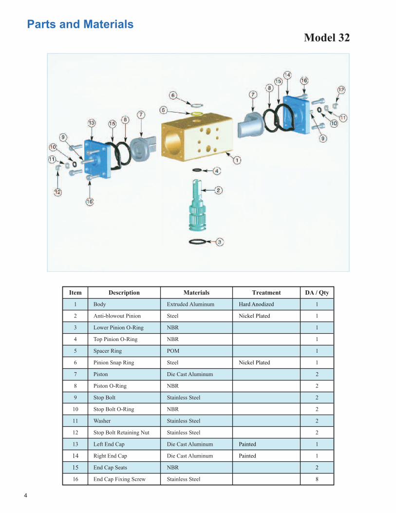
Item Description Materials Treatment DA / Qty
1
2
3
4
5
6
7
8
9
10
11
12
13
14
15
Body Extruded Aluminum
16
1
Anti-blowout Pinion Steel 1
Lower Pinion O-Ring NBR 1
Spacer Ring
NBR 1Top Pinion O-Ring
POM 1
Pinion Snap Ring Steel 1
Piston Die Cast Aluminum 2
Piston O-Ring NBR 2
Stop Bolt Stainless Steel 2
Stop Bolt O-Ring NBR
Stainless Steel
2
Washer 2
Stop Bolt Retaining Nut Stainless Steel 2
1Die Cast AluminumLeft End Cap
Right End Cap Die Cast Aluminum 1
End Cap Seats NBR
Hard Anodized
Nickel Plated
2
8End Cap Fixing Screw Stainless Steel
Model 32
Painted
Nickel Plated
Painted
4
Parts and Materials
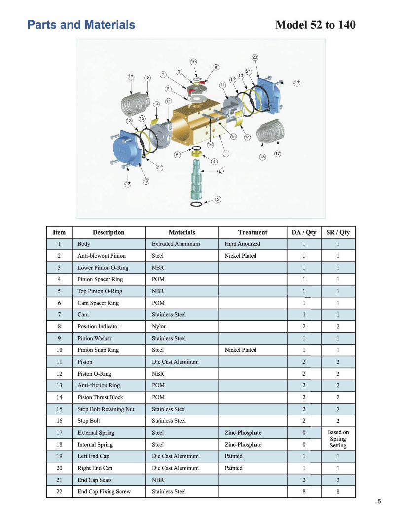

Item Description Materials Treatment DA / Qty SR / Qty1
2
3
4
5
6
7
8
9
10
11
12
13
14
15
Body Extruded Aluminum
16
1 1
Anti-blowout Pinion Steel
17
1 1
18
19
20
21
22
23
24
25
26
27
28
29
Lower Pinion O-Ring NBR 1 1
Top Pinion O-Ring NBR 1 1
Pinion Spacer Ring POM 1 1
Pinion Snap Ring Steel 1 1
Piston Die Cast Aluminum 2 2
2Piston O-Ring NBR 2
Anti-friction Ring PTFE 15% Graphite 2
Piston Thrust Block POM
NBR
4 (6)*
2
Stop Bolt O-Ring 2
Washer Stainless Steel 2
2Stainless SteelStop Bolt Retaining Nut
Stop Bolt Stainless Steel 2
External Spring Steel
Hard Anodized
Nickel Plated
Nickel Plated
Zinc-Phosphate 0
4 (6)*
2
2
2
2
0
0
1
Based onSpringSetting
Central Spring
Internal Spring
Left End Cap
Right End Cap
End Cap Fixing Screw
Steel
Steel
Die Cast Aluminum
Die Cast Aluminum
Stainless Steel
Zinc-Phosphate
Zinc-Phosphate
Painted
Painted 1
8 (12)*
1
1
8 (12)*
30
31
End Cap O-Ring
End Cap Fixing Screw
Precompressed Spring
Anti-friction Ring
Pinion Washer
Closed Position Adjustment Upon Request
Plate
Coupling
Anti-friction Ring
Stop Screw
Stop Bolt Retaining Nut
Fixing Screws
NBR
NBR
Steel
PTFE 15% Graphite
Stainless Steel
GGG40
Steel
Steel
Stainless Steel
Stainless Steel
PTFE
Zinc-Phosphate
Painted
Nickel Plated
Zinc Plated
2
2
0
1
1
1
1
1
1
1
4
1
1
1
1
1
4
2
2
1
1
Based onSpring Setting
Model 160 - 200 - 270Model 270 Only
Closed position adjustmentupon request
6
Parts and Materials
* (6) and (12) Valid for Model 270 Only


MOD
SR52
SETSpringTorque(in.lbs)
Start End
Air Supply Pressure (PSI)60 70
Torque Output Spring Return Actuators (in.lbs.)Start End Start End
80 90 100 115
Start End Start End Start End Start End030405*
465772
6682
105
80 47 104 70 127 94 150 11770 31 93
785532
116101
7855
140125
10178
163148
125102 183 137
SR63030405*
7185111
128152196
149 79 191 121 233 162 275 204136 54 177
1519653
219193
13895
261235
180136
303276
222178 339 241
SR75030405*
SR85030405*
SR100030405*
SR115
SR125
SR160
SR200
SR270
030405*030405*
040506*030405
050607
06*
08*
133162205
249303380
215361248417321536318389489
564691860
275247
13783
351 212 426 288 502 363322 158 398 234 473 309 549 385279 81 354 157 430 232 505 308 618 421
387 211 498 322 609 432 720 543354 155 465 265 576 376 687 487 797 633
392 146 503 257 614 368 725 478 891 645628 329 801 502 973 674 1146 847558 203 730
630375206
903802
548378
1075975
720551
12481147
893723 1406 982
1044958
541365
132912431067 352
650827538
6258001432
1133957 1615 1112 1900 1397
15281352 637
935 18131638
1220922 1923
2098 15051207 2350 1635
718808
1055
1770223026552637312437264664804489389832
1073516735
131314771913
2841332741863752469953276867
125491394715336
13511261
2447
53014788
114951053995848637
640477
1350
40353080
6884541539552486
1725 10151636 8511388 415
31622737
20741507
663961265453 3613
44455400
1492110310139651300912063
885073815912
2099 138920101762
1226789
388634522983 1443
22402779
748668225893
579550083539
18221172741631915363
1361912150106819221 186721252122098
19619205742153016920
1545913990
72888182 6385
4925 8591 6175 10562 8137
1594727115209651741623053
37154175 2963
2167 4421 2828 5475 3865
20993072153819742758
25111164160017632474
23842136
Sizing and SelectionTorque Output - Spring Return
9
* Standard Spring Set
Spring Start
Spring End
Air Start
Air End
- at the beginning of the spring cycle the springs are fully compressed; the stored energyand torque output of the spring is at the maximum
- at the end of the spring cycle the springs are uncompressed and the torque output of thespring is at the minimum
- at the beginning of the air cycle the springs are uncompressed and the air torque outputis at the maximum
- at the end of the air cycle the springs are fully compressed and the air torque output is atthe minimum, due to increasing energy required to compress springs
SR140030405*
103611341453
195821262728
1910 856 2412 1358 2914 1861 3408 23551810 668 2312 1170 2814 1672 2668381021663308
1979 515 2481 1017 276942332013347715112975

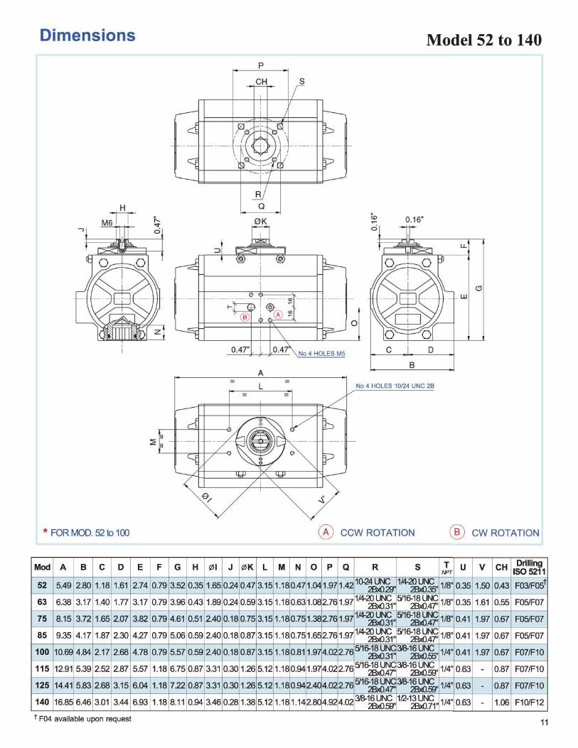
Dimensions Model 32, 160, 200, 270
10
Kit for Closed Position Adjustment Optional Model 160, 200, 270
F03
F10/F12
F14
F16
0.35
1.06
1.42
1.81
Mod
32
160
200
270
A B C D E F G H I L M N O P R S T U V W Z Y X CH DrillingISO 5211
0.63
1.89
1.52
3.23
0.35
1.06
1.41
1.81
0.47
1.42
1.90
2.37
-
2.50
3.11
4.37
-
2.20
2.52
3.11
-
-
-
-
1.77
2.03
2.68
Q
-
6.29
7.48
9.05
1/8"
1/4"
1/4"
1/4"
-
3.21
3.46
4.76
0.46
1.38
1.97
1.97
0.47
1.26
1.54
2.05
-
4.02
-
-
3/8-16 UNC
10-24 UNC2Bx0.29"
2Bx0.59"1/2-13 UNC
2Bx0.71"5/8-11 UNC
2Bx0.98"3/4-10 UNC
2Bx1.18"
1.42
4.92
5.51
6.50
4.33
20.55
22.64
26.46
1.77
7.36
8.58
11.42
0.89
3.43
4.29
5.71
0.89
3.94
4.29
5.71
2.56
8.58
10.59
14.21
1.77
7.40
9.41
13.03
0.39
1.18
1.42
1.42
1.97
3.15
3.15
3.15
-
5.12
5.12
5.12 *
* only with square connection at 45°
CCW ROTATION CW ROTATION
No 4 HOLES M5
HOLES 10/24 UNC 2B x 0.23"No 2 HOLES M5 x 0.23"
VALID FOR MOD. 200 AND 270 VALID FOR MOD. 160
VALID FO
R MOD. 32
No 6 HOLES M5
DETAIL
*0.79 FOR MOD. 32
DEPTH X
UPON REQUEST
NPT
SEE DETAIL
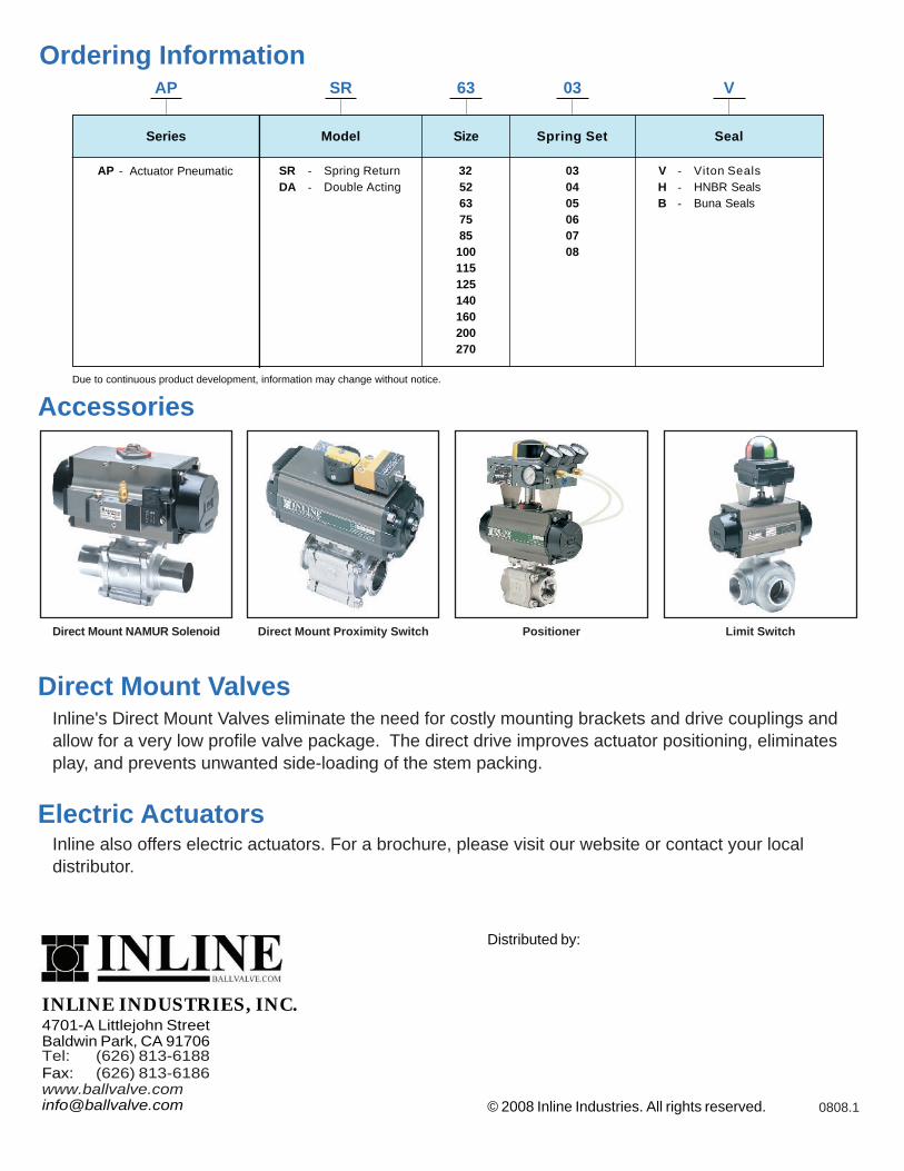
Ordering InformationAP SR 63
Series Model Size Spring Set Seal
AP SRDA
Spring ReturnDouble Acting
V - Viton Seals
Due to continuous product development, information may change without notice.
H HNBR Seals
03
-
V
520304
- Actuator Pneumatic - -
7585
100115125
160200
63
270
05060708
32
Accessories
Direct Mount NAMUR Solenoid Limit SwitchDirect Mount Proximity Switch Positioner
INLINE INDUSTRIES, INC.4701-A Littlejohn StreetBaldwin Park, CA 91706
Fax:
Distributed by:
© 2008 Inline Industries. All rights reserved.
Tel: (626) 813-6188(626) 813-6186
www.ballvalve.com0808.1
Direct Mount Valves
Electric ActuatorsInline also offers electric actuators. For a brochure, please visit our website or contact your localdistributor.
Inline's Direct Mount Valves eliminate the need for costly mounting brackets and drive couplings andallow for a very low profile valve package. The direct drive improves actuator positioning, eliminatesplay, and prevents unwanted side-loading of the stem packing.
140
B Buna Seals -