Embed Size (px)
Citation preview

ENGINEERING YOUR SUCCESS.
aerospaceclimate controlelectromechanicalfiltrationfluid & gas handlinghydraulicspneumaticsprocess controlsealing & shielding
Pneumatic Actuator ProductsP1Q Series Global Compact Cylinders
Catalog 0960-E
800.696.6165 www.comoso.com
Parker Hannifin CorporationPneumatic DivisionWadsworth, Ohio www.parker.com/pneumatics
P1Q Series Global Compact Cylinders Catalog 0960-E
Warning, Offer of Sale
Features ...................................................................................................................................... 3
Technical Information General Technical Data ........................................................................................................ 4Operating Environmental Data ............................................................................................. 4Material Specifications ......................................................................................................... 4Main Data ............................................................................................................................ 5Cylinder Forces ................................................................................................................... 5Front Profiles By Bore Size .................................................................................................. 5
Application Guide ........................................................................................................................ 6
Dimensions Non-Magnet ........................................................................................................................ 7Magnet ................................................................................................................................ 8Male Rod Thread Option ..................................................................................................... 9
Model Number Index ................................................................................................................. 10
Non-Magnetic Common Part Numbers ..................................................................................... 11
Magnetic Common Part Numbers ............................................................................................. 12
Mountings Flange ............................................................................................................................... 13Foot .................................................................................................................................. 13Clevis ................................................................................................................................ 14Lock Nut ........................................................................................................................... 14Rod Eye ............................................................................................................................ 15Rod Clevis ......................................................................................................................... 15
Accessories Sensors ........................................................................................................................16-17Air Quality Chart ................................................................................................................ 18
Safety Guide .........................................................................................................................20-21
Offer Of Sale .............................................................................................................................. 22
! WARNINGFAILURE OR IMPROPER SELECTION OR IMPROPER USE OF THE PRODUCTS AND/OR SYSTEMS DESCRIBED HEREIN OR RELATED ITEMS CAN CAUSE DEATH, PERSONAL INJURY AND PROPERTY DAMAGE.This document and other information from Parker Hannifin Corporation, its subsidiaries and authorized distributors provide product and/or system options for further investigation by users having technical expertise. It is important that you analyze all aspects of your application including consequences of any failure, and review the information concerning the product or system in the current product catalog. Due to the variety of operating conditions and applications for these products or systems, the user, through its own analysis and testing, is solely responsible for making the final selection of the products and systems and assuring that all performance, safety and warning requirements of the application are met.The products described herein, including without limitation, product features, specifications, designs, availability and pricing, are subject to change by Parker Hannifin Corporation and its subsidiaries at any time without notice.
Offer of SaleThe items described in this document are hereby offered for sale by Parker Hannifin Corporation, its subsidiaries or its authorized distributors. This offer and its acceptance are governed by the provisions stated on the separate page of this document entitled “Offer of Sale”.
© Copyright 2012, 2011 Parker Hannifin Corporation. All Rights Reserved
800.696.6165 www.comoso.com
3 Parker Hannifin CorporationPneumatic DivisionWadsworth, Ohio www.parker.com/pneumatics
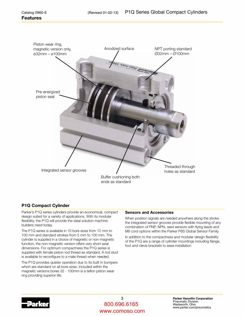
Parker’s P1Q series cylinders provide an economical, compact design suited for a variety of applications. With its modular flexibility, the P1Q will provide the ideal solution machine builders need today.
The P1Q series is available in 10 bore sizes from 12 mm to 100 mm and standard strokes from 5 mm to 100 mm. The cylinder is supplied in a choice of magnetic or non-magnetic function, the non-magnetic version offers very short axial dimensions. For optimum compactness the P1Q series is supplied with female piston rod thread as standard. A rod stud is available to reconfigure to a male thread when needed.
The P1Q provides quieter operation due to its built in bumpers which are standard on all bore sizes. Included within the magnetic versions bores 32 - 100mm is a teflon piston wear ring providing superior life.
Sensors and AccessoriesWhen position signals are needed anywhere along the stroke the integrated sensor grooves provide flexible mounting of any combination of PNP, NPN, reed sensors with flying leads and M8 cord options within the Parker P8S Global Sensor Family.
In addition to the compactness and modular design flexibility of the P1Q are a range of cylinder mountings including flange, foot and clevis brackets to ease installation
Catalog 0960-E
FeaturesP1Q Series Global Compact Cylinders
Pre-energized piston seal
Piston wear ring, magnetic version only,ø32mm – ø100mm
Integrated sensor grooves
Anodized surface NPT porting standard Ø32mm – Ø100mm
Threaded through holes as standard
Buffer cushioning both ends as standard
P1Q Compact Cylinder
(Revised 01-02-13)
800.696.6165 www.comoso.com
4 Parker Hannifin CorporationPneumatic DivisionWadsworth, Ohio www.parker.com/pneumatics
Catalog 0960-E
Technical Information P1Q Series Global Compact Cylinders
General technical dataProduct type Compact
Bore size 12 - 100 mm
Stroke length 100 mm
Versions P1Q...B/E Double acting, Non magnetic
P1Q...G/N Double acting, Magnetic
Cushioning Elastic bumpers
Position sensing Proximity sensor
Installation Direct Through holes
Female thread on front and rear end face
Accessories Cylinder mountings
Mounting position Any
Operating and environmental data Operating medium For best possible service life and trouble-free operation it is recommended to use dry, filtered compressed air to ISO 8573-
1:2010 quality class 3.4.3. This specifies a dew point of +3°C for indoor operation (a lower dew point should be selected for outdoor operation) and is in line with the air quality from most standard compressors with a standard filter. Refer to page 18.
Operating pressure 0.5 bar to 10 bar
Ambient temperature -5°C to 60°C
Pre-lubricated Further lubrication is normally not necessary. If additional lubrication is introduced it must be continued.
Corrosion resistance High resistance to corrosion and chemicals. Materials and surface treatment have been selected for industrial applications where solvents and detergents are frequently used.
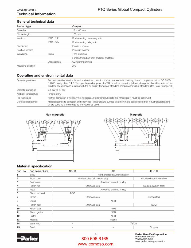
Material specificationPart No Part name / bore 12 - 25 32 40 - 100
1 Body Hard anodised aluminium alloy
2 Front cover Hard anodised aluminium alloy Anodised aluminium alloy
3 Rear cover Anodised aluminium alloy
4 Piston rod Stainless steel Medium carbon steel
5 Piston Anodised aluminium alloy
6 Piston rod seal NBR
7 Circlip Stainless steel Spring steel
8 O ring NBR
9 Piston bolt Stainless steel SCM
10 Piston seal NBR
11 Piston gasket NBR
12 Buffer NBR
13 Magnet Plastic
14 Wear ring – Teflon
15 Bush – – Copper
Non magnetic Magnetic
800.696.6165 www.comoso.com
5 Parker Hannifin CorporationPneumatic DivisionWadsworth, Ohio www.parker.com/pneumatics
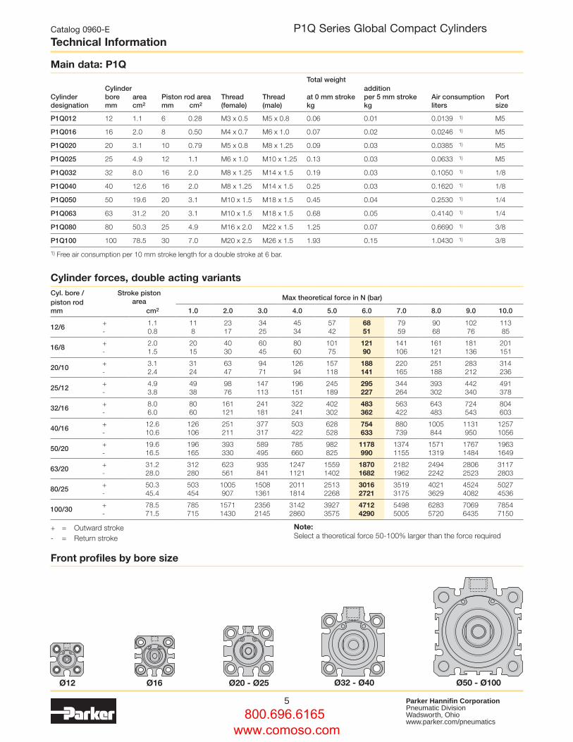
Main data: P1QTotal weight
Cylinderdesignation
Cylinderboremm
areacm2
Piston rod area mm cm2
Thread(female)
Thread(male)
at 0 mm strokekg
addition per 5 mm strokekg
Air consumption liters
Port size
P1Q012 12 1.1 6 0.28 M3 x 0.5 M5 x 0.8 0.06 0.01 0.0139 1) M5
P1Q016 16 2.0 8 0.50 M4 x 0.7 M6 x 1.0 0.07 0.02 0.0246 1) M5
P1Q020 20 3.1 10 0.79 M5 x 0.8 M8 x 1.25 0.09 0.03 0.0385 1) M5
P1Q025 25 4.9 12 1.1 M6 x 1.0 M10 x 1.25 0.13 0.03 0.0633 1) M5
P1Q032 32 8.0 16 2.0 M8 x 1.25 M14 x 1.5 0.19 0.03 0.1050 1) 1/8
P1Q040 40 12.6 16 2.0 M8 x 1.25 M14 x 1.5 0.25 0.03 0.1620 1) 1/8
P1Q050 50 19.6 20 3.1 M10 x 1.5 M18 x 1.5 0.45 0.04 0.2530 1) 1/4
P1Q063 63 31.2 20 3.1 M10 x 1.5 M18 x 1.5 0.68 0.05 0.4140 1) 1/4
P1Q080 80 50.3 25 4.9 M16 x 2.0 M22 x 1.5 1.25 0.07 0.6690 1) 3/8
P1Q100 100 78.5 30 7.0 M20 x 2.5 M26 x 1.5 1.93 0.15 1.0430 1) 3/8
1) Free air consumption per 10 mm stroke length for a double stroke at 6 bar.
Cylinder forces, double acting variantsCyl. bore / piston rodmm
Stroke piston area Max theoretical force in N (bar)
cm2 1.0 2.0 3.0 4.0 5.0 6.0 7.0 8.0 9.0 10.0
12/6+-
1.10.8
118
23 17
3425
4534
5742
6851
7959
9068
10276
11385
16/8+-
2.0 1.5
2015
4030
6045
8060
10175
12190
141106
161121
181136
201151
20/10 +-
3.1 2.4
3124
6347
9471
12694
157118
188141
220165
251188
283212
314236
25/12 +-
4.9 3.8
4938
9876
147113
196151
245189
295227
344264
393302
442340
491378
32/16+-
8.06.0
8060
161121
241181
322241
402302
483362
563422
643483
724543
804603
40/16+-
12.610.6
126106
251211
377317
503422
628528
754633
880739
1005844
1131950
12571056
50/20 +-
19.616.5
196165
393330
589495
785660
982825
1178990
13741155
15711319
17671484
19631649
63/20 +-
31.228.0
312280
623561
935841
12471121
15591402
18701682
21821962
24942242
28062523
31172803
80/25+-
50.345.4
503454
1005907
15081361
20111814
25132268
30162721
35193175
40213629
45244082
50274536
100/30+-
78.571.5
785715
15711430
23562145
31422860
39273575
47124290
54985005
62835720
70696435
78547150
+ = Outward stroke- = Return stroke
Note: Select a theoretical force 50-100% larger than the force required
Catalog 0960-E
Technical Information P1Q Series Global Compact Cylinders
Front profiles by bore size
Ø12 Ø32 - Ø40Ø16 Ø50 - Ø100Ø20 - Ø25
800.696.6165 www.comoso.com
6 Parker Hannifin CorporationPneumatic DivisionWadsworth, Ohio www.parker.com/pneumatics
Catalog 0960-E
Application Guide P1Q Series Global Compact Cylinders
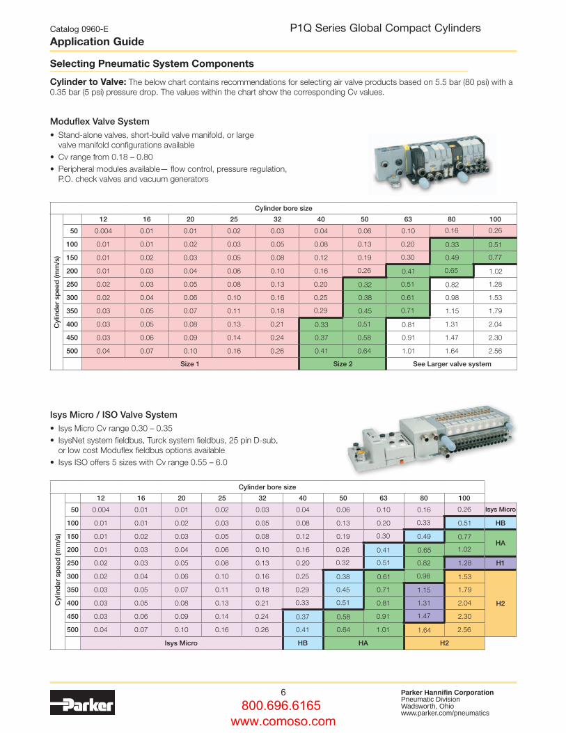
Selecting Pneumatic System Components
Cylinder bore size
Cyl
ind
er s
pee
d (m
m/s
)
12 16 20 25 32 40 50 63 80 100
50 0.004 0.01 0.01 0.02 0.03 0.04 0.06 0.10 0.16 0.26
100 0.01 0.01 0.02 0.03 0.05 0.08 0.13 0.20 0.33 0.51
150 0.01 0.02 0.03 0.05 0.08 0.12 0.19 0.30 0.49 0.77
200 0.01 0.03 0.04 0.06 0.10 0.16 0.26 0.41 0.65 1.02
250 0.02 0.03 0.05 0.08 0.13 0.20 0.32 0.51 0.82 1.28
300 0.02 0.04 0.06 0.10 0.16 0.25 0.38 0.61 0.98 1.53
350 0.03 0.05 0.07 0.11 0.18 0.29 0.45 0.71 1.15 1.79
400 0.03 0.05 0.08 0.13 0.21 0.33 0.51 0.81 1.31 2.04
450 0.03 0.06 0.09 0.14 0.24 0.37 0.58 0.91 1.47 2.30
500 0.04 0.07 0.10 0.16 0.26 0.41 0.64 1.01 1.64 2.56
Size 1 Size 2 See Larger valve system
Moduflex Valve System • Stand-alone valves, short-build valve manifold, or large
valve manifold configurations available• Cv range from 0.18 – 0.80 • Peripheral modules available— flow control, pressure regulation,
P.O. check valves and vacuum generators
Isys Micro / ISO Valve System • Isys Micro Cv range 0.30 – 0.35• IsysNet system fieldbus, Turck system fieldbus, 25 pin D-sub,
or low cost Moduflex fieldbus options available• Isys ISO offers 5 sizes with Cv range 0.55 – 6.0
Cylinder to Valve: The below chart contains recommendations for selecting air valve products based on 5.5 bar (80 psi) with a 0.35 bar (5 psi) pressure drop. The values within the chart show the corresponding Cv values.
Cylinder bore size
12 16 20 25 32 40 50 63 80 100
Cyl
ind
er s
pee
d (m
m/s
)
50 0.004 0.01 0.01 0.02 0.03 0.04 0.06 0.10 0.16 0.26 Isys Micro
100 0.01 0.01 0.02 0.03 0.05 0.08 0.13 0.20 0.33 0.51 HB
150 0.01 0.02 0.03 0.05 0.08 0.12 0.19 0.30 0.49 0.77HA
200 0.01 0.03 0.04 0.06 0.10 0.16 0.26 0.41 0.65 1.02
250 0.02 0.03 0.05 0.08 0.13 0.20 0.32 0.51 0.82 1.28 H1
300 0.02 0.04 0.06 0.10 0.16 0.25 0.38 0.61 0.98 1.53
H2
350 0.03 0.05 0.07 0.11 0.18 0.29 0.45 0.71 1.15 1.79
400 0.03 0.05 0.08 0.13 0.21 0.33 0.51 0.81 1.31 2.04
450 0.03 0.06 0.09 0.14 0.24 0.37 0.58 0.91 1.47 2.30
500 0.04 0.07 0.10 0.16 0.26 0.41 0.64 1.01 1.64 2.56
Isys Micro HB HA H2
800.696.6165 www.comoso.com
7 Parker Hannifin CorporationPneumatic DivisionWadsworth, Ohio www.parker.com/pneumatics
Catalog 0960-E
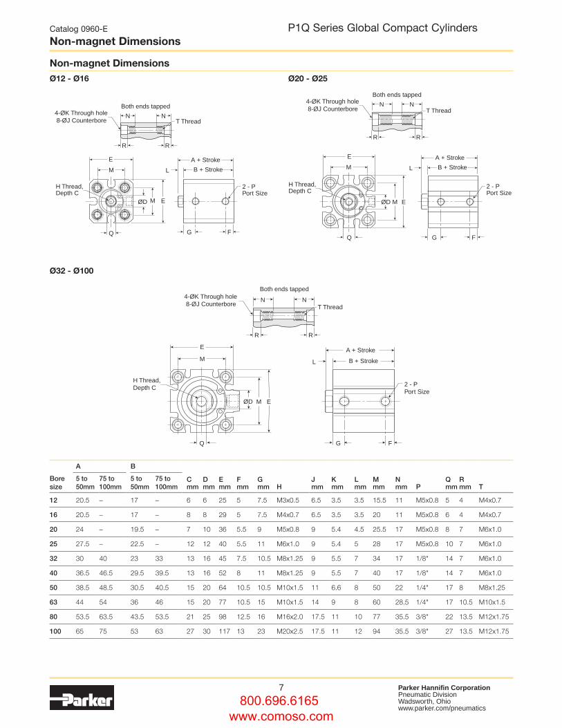
Non-magnet DimensionsP1Q Series Global Compact Cylinders
E
ØD
A + Stroke
B + StrokeM
EM
L
N NT Thread
R R
Both ends tapped
GQ
4-ØK Through hole 8-ØJ Counterbore
F
H Thread,Depth C
2 - PPort Size
Boresize
A B
Dmm
Emm
Fmm
Gmm H
Jmm
Kmm
Lmm
Mmm
Nmm P
Qmm
Rmm T
5 to 50mm
75 to 100mm
5 to 50mm
75 to 100mm
Cmm
12 20.5 – 17 – 6 6 25 5 7.5 M3x0.5 6.5 3.5 3.5 15.5 11 M5x0.8 5 4 M4x0.7
16 20.5 – 17 – 8 8 29 5 7.5 M4x0.7 6.5 3.5 3.5 20 11 M5x0.8 6 4 M4x0.7
20 24 – 19.5 – 7 10 36 5.5 9 M5x0.8 9 5.4 4.5 25.5 17 M5x0.8 8 7 M6x1.0
25 27.5 – 22.5 – 12 12 40 5.5 11 M6x1.0 9 5.4 5 28 17 M5x0.8 10 7 M6x1.0
32 30 40 23 33 13 16 45 7.5 10.5 M8x1.25 9 5.5 7 34 17 1/8" 14 7 M6x1.0
40 36.5 46.5 29.5 39.5 13 16 52 8 11 M8x1.25 9 5.5 7 40 17 1/8" 14 7 M6x1.0
50 38.5 48.5 30.5 40.5 15 20 64 10.5 10.5 M10x1.5 11 6.6 8 50 22 1/4" 17 8 M8x1.25
63 44 54 36 46 15 20 77 10.5 15 M10x1.5 14 9 8 60 28.5 1/4" 17 10.5 M10x1.5
80 53.5 63.5 43.5 53.5 21 25 98 12.5 16 M16x2.0 17.5 11 10 77 35.5 3/8" 22 13.5 M12x1.75
100 65 75 53 63 27 30 117 13 23 M20x2.5 17.5 11 12 94 35.5 3/8" 27 13.5 M12x1.75
Non-magnet DimensionsØ12 - Ø16 Ø20 - Ø25
Ø32 - Ø100
E
ØD
A + Stroke
B + StrokeM L
G F
EM
Q
H Thread,Depth C
2 - PPort Size
N N
Both ends tapped4-ØK Through hole 8-ØJ Counterbore T Thread
R R
ØD
A + Stroke
B + Stroke
E
M L
EM
Q
H Thread,Depth C
G F
2 - PPort Size
N N
Both ends tapped4-ØK Through hole 8-ØJ Counterbore T Thread
R R
800.696.6165 www.comoso.com
8 Parker Hannifin CorporationPneumatic DivisionWadsworth, Ohio www.parker.com/pneumatics
E
ØD
A + Stroke
B + StrokeM
EM
L
N NT Thread
R R
Both ends tapped
GQ
4-ØK Through hole 8-ØJ Counterbore
F
H Thread,Depth C
2 - PPort Size
E
ØD
A + Stroke
B + StrokeM L
G F
EM
Q
H Thread,Depth C
2 - PPort Size
N N
Both ends tapped4-ØK Through hole 8-ØJ Counterbore T Thread
R R
ØD
A + Stroke
B + Stroke
E
M L
EM
Q
H Thread,Depth C
G F
2 - PPort Size
N N
Both ends tapped4-ØK Through hole 8-ØJ Counterbore T Thread
R R
Catalog 0960-E
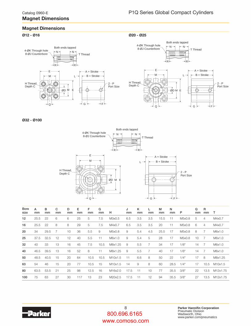
Magnet DimensionsP1Q Series Global Compact Cylinders
Bore size
Amm
Bmm
Cmm
Dmm
Emm
Fmm
Gmm H
Jmm
Kmm
Lmm
Mmm
Nmm P
Qmm
Rmm T
12 25.5 22 6 6 25 5 7.5 M3x0.5 6.5 3.5 3.5 15.5 11 M5x0.8 5 4 M4x0.7
16 25.5 22 8 8 29 5 7.5 M4x0.7 6.5 3.5 3.5 20 11 M5x0.8 6 4 M4x0.7
20 34 29.5 7 10 36 5.5 9 M5x0.8 9 5.4 4.5 25.5 17 M5x0.8 8 7 M6x1.0
25 37.5 32.5 12 12 40 5.5 11 M6x1.0 9 5.4 5 28 17 M5x0.8 10 7 M6x1.0
32 40 33 13 16 45 7.5 10.5 M8x1.25 9 5.5 7 34 17 1/8" 14 7 M6x1.0
40 46.5 39.5 13 16 52 8 11 M8x1.25 9 5.5 7 40 17 1/8" 14 7 M6x1.0
50 48.5 40.5 15 20 64 10.5 10.5 M10x1.5 11 6.6 8 50 22 1/4" 17 8 M8x1.25
63 54 46 15 20 77 10.5 15 M10x1.5 14 9 8 60 28.5 1/4" 17 10.5 M10x1.5
80 63.5 53.5 21 25 98 12.5 16 M16x2.0 17.5 11 10 77 35.5 3/8" 22 13.5 M12x1.75
100 75 63 27 30 117 13 23 M20x2.5 17.5 11 12 94 35.5 3/8" 27 13.5 M12x1.75
Magnet DimensionsØ12 - Ø16 Ø20 - Ø25
Ø32 - Ø100
800.696.6165 www.comoso.com
9 Parker Hannifin CorporationPneumatic DivisionWadsworth, Ohio www.parker.com/pneumatics
Male Rod Thread Dimensions
Catalog 0960-E
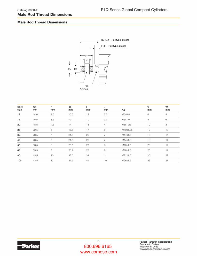
Male Rod Thread DimensionsP1Q Series Global Compact Cylinders
Bore size
B2mm
Fmm
Hmm
Imm
Jmm K2
Vmm
Wmm
12 14.0 3.5 10.5 18 2.7 M5x0.8 6 5
16 15.5 3.5 12 10 3.2 M6x1.0 8 6
20 18.5 4.5 14 13 4 M8x1.25 10 8
25 22.5 5 17.5 17 5 M10x1.25 12 10
32 28.5 7 21.5 22 7 M14x1.5 16 14
40 28.5 7 21.5 22 7 M14x1.5 16 14
50 33.5 8 25.5 27 8 M18x1.5 20 17
63 33.5 8 25.2 27 8 M18x1.5 20 17
80 43.5 10 33.5 32 11 M22x1.5 25 22
100 43.5 12 31.5 41 16 M26x1.5 32 27
B2 (B2 + Pull type stroke)
F (F + Pull type stroke)
H
J
ØV K2
I
W2-Sides
800.696.6165 www.comoso.com
10 Parker Hannifin CorporationPneumatic DivisionWadsworth, Ohio www.parker.com/pneumatics
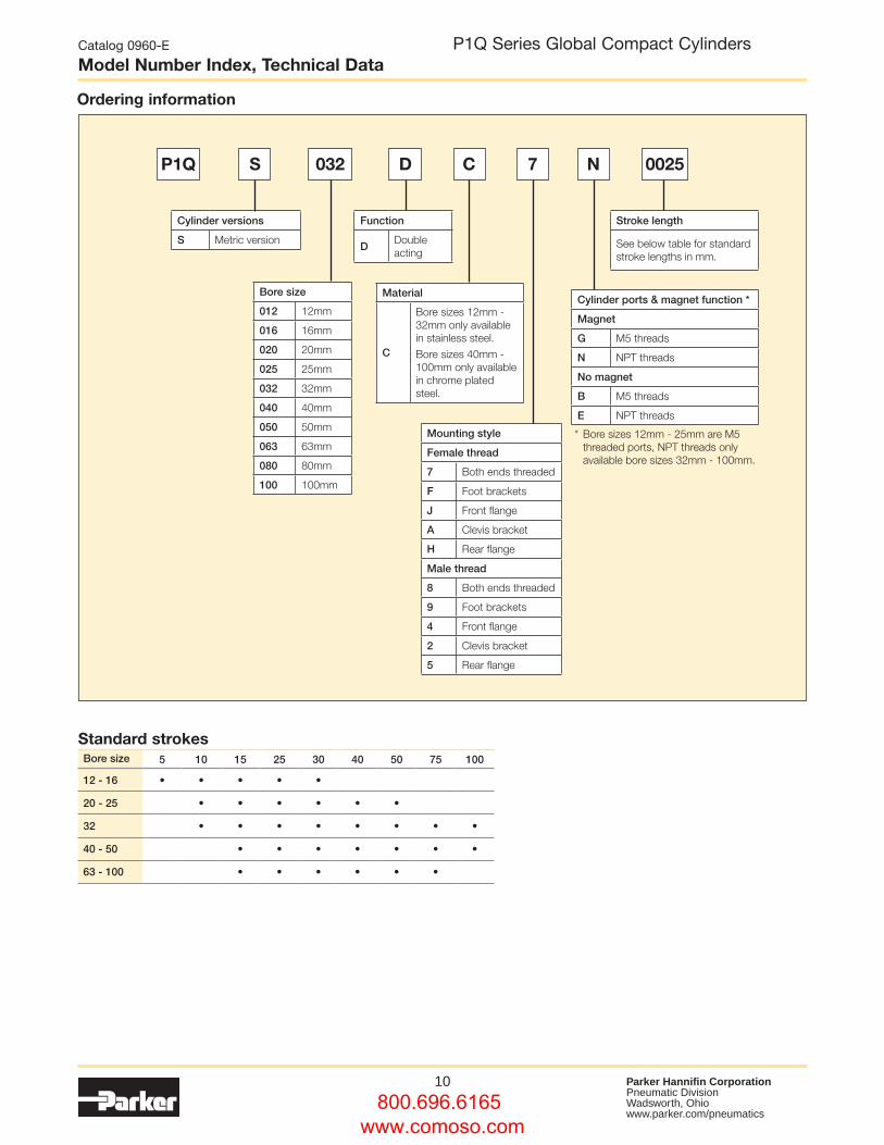
Stroke length
See below table for standard stroke lengths in mm.
Function
DDouble acting
Material
C
Bore sizes 12mm - 32mm only available in stainless steel.
Bore sizes 40mm - 100mm only available in chrome plated steel.
Mounting style
Female thread
7 Both ends threaded
F Foot brackets
J Front flange
A Clevis bracket
H Rear flange
Male thread
8 Both ends threaded
9 Foot brackets
4 Front flange
2 Clevis bracket
5 Rear flange
Cylinder versions
S Metric version
Cylinder ports & magnet function *
Magnet
G M5 threads
N NPT threads
No magnet
B M5 threads
E NPT threads
* Bore sizes 12mm - 25mm are M5 threaded ports, NPT threads only available bore sizes 32mm - 100mm.
Bore size
012 12mm
016 16mm
020 20mm
025 25mm
032 32mm
040 40mm
050 50mm
063 63mm
080 80mm
100 100mm
P1Q S 032 D C 7 N 0025
Catalog 0960-E
Model Number Index, Technical DataP1Q Series Global Compact Cylinders
Ordering information
Standard strokesBore size 5 10 15 25 30 40 50 75 100
12 - 16 • • • • •
20 - 25 • • • • • •
32 • • • • • • • •
40 - 50 • • • • • • •
63 - 100 • • • • • •
800.696.6165 www.comoso.com
11 Parker Hannifin CorporationPneumatic DivisionWadsworth, Ohio www.parker.com/pneumatics
Catalog 0960-E
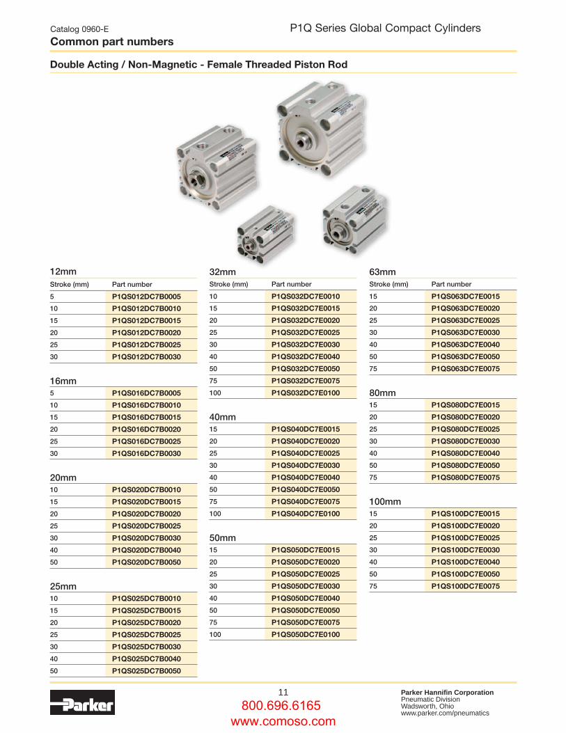
Common part numbersP1Q Series Global Compact Cylinders
12mmStroke (mm) Part number
5 P1QS012DC7B0005
10 P1QS012DC7B0010
15 P1QS012DC7B0015
20 P1QS012DC7B0020
25 P1QS012DC7B0025
30 P1QS012DC7B0030
16mm5 P1QS016DC7B0005
10 P1QS016DC7B0010
15 P1QS016DC7B0015
20 P1QS016DC7B0020
25 P1QS016DC7B0025
30 P1QS016DC7B0030
20mm10 P1QS020DC7B0010
15 P1QS020DC7B0015
20 P1QS020DC7B0020
25 P1QS020DC7B0025
30 P1QS020DC7B0030
40 P1QS020DC7B0040
50 P1QS020DC7B0050
25mm10 P1QS025DC7B0010
15 P1QS025DC7B0015
20 P1QS025DC7B0020
25 P1QS025DC7B0025
30 P1QS025DC7B0030
40 P1QS025DC7B0040
50 P1QS025DC7B0050
32mmStroke (mm) Part number
10 P1QS032DC7E0010
15 P1QS032DC7E0015
20 P1QS032DC7E0020
25 P1QS032DC7E0025
30 P1QS032DC7E0030
40 P1QS032DC7E0040
50 P1QS032DC7E0050
75 P1QS032DC7E0075
100 P1QS032DC7E0100
40mm15 P1QS040DC7E0015
20 P1QS040DC7E0020
25 P1QS040DC7E0025
30 P1QS040DC7E0030
40 P1QS040DC7E0040
50 P1QS040DC7E0050
75 P1QS040DC7E0075
100 P1QS040DC7E0100
50mm15 P1QS050DC7E0015
20 P1QS050DC7E0020
25 P1QS050DC7E0025
30 P1QS050DC7E0030
40 P1QS050DC7E0040
50 P1QS050DC7E0050
75 P1QS050DC7E0075
100 P1QS050DC7E0100
63mmStroke (mm) Part number
15 P1QS063DC7E0015
20 P1QS063DC7E0020
25 P1QS063DC7E0025
30 P1QS063DC7E0030
40 P1QS063DC7E0040
50 P1QS063DC7E0050
75 P1QS063DC7E0075
80mm15 P1QS080DC7E0015
20 P1QS080DC7E0020
25 P1QS080DC7E0025
30 P1QS080DC7E0030
40 P1QS080DC7E0040
50 P1QS080DC7E0050
75 P1QS080DC7E0075
100mm15 P1QS100DC7E0015
20 P1QS100DC7E0020
25 P1QS100DC7E0025
30 P1QS100DC7E0030
40 P1QS100DC7E0040
50 P1QS100DC7E0050
75 P1QS100DC7E0075
Double Acting / Non-Magnetic - Female Threaded Piston Rod
800.696.6165 www.comoso.com
12 Parker Hannifin CorporationPneumatic DivisionWadsworth, Ohio www.parker.com/pneumatics
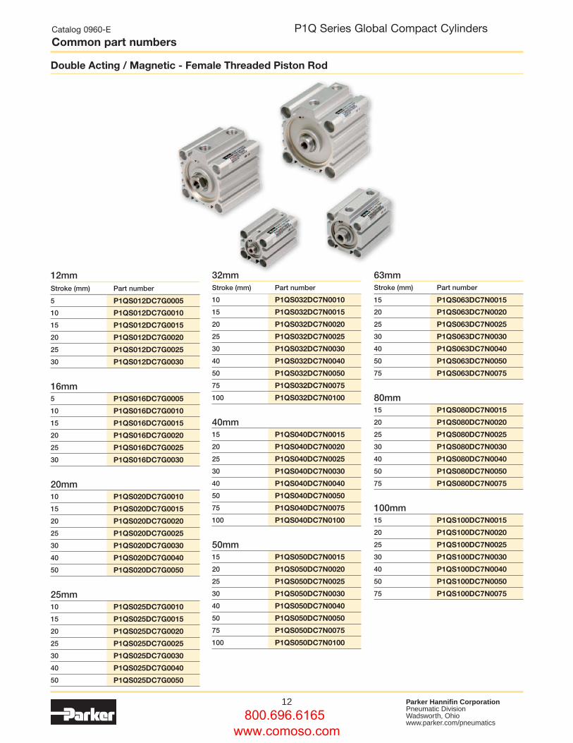
12mmStroke (mm) Part number
5 P1QS012DC7G0005
10 P1QS012DC7G0010
15 P1QS012DC7G0015
20 P1QS012DC7G0020
25 P1QS012DC7G0025
30 P1QS012DC7G0030
16mm5 P1QS016DC7G0005
10 P1QS016DC7G0010
15 P1QS016DC7G0015
20 P1QS016DC7G0020
25 P1QS016DC7G0025
30 P1QS016DC7G0030
20mm10 P1QS020DC7G0010
15 P1QS020DC7G0015
20 P1QS020DC7G0020
25 P1QS020DC7G0025
30 P1QS020DC7G0030
40 P1QS020DC7G0040
50 P1QS020DC7G0050
25mm10 P1QS025DC7G0010
15 P1QS025DC7G0015
20 P1QS025DC7G0020
25 P1QS025DC7G0025
30 P1QS025DC7G0030
40 P1QS025DC7G0040
50 P1QS025DC7G0050
32mmStroke (mm) Part number
10 P1QS032DC7N0010
15 P1QS032DC7N0015
20 P1QS032DC7N0020
25 P1QS032DC7N0025
30 P1QS032DC7N0030
40 P1QS032DC7N0040
50 P1QS032DC7N0050
75 P1QS032DC7N0075
100 P1QS032DC7N0100
40mm15 P1QS040DC7N0015
20 P1QS040DC7N0020
25 P1QS040DC7N0025
30 P1QS040DC7N0030
40 P1QS040DC7N0040
50 P1QS040DC7N0050
75 P1QS040DC7N0075
100 P1QS040DC7N0100
50mm15 P1QS050DC7N0015
20 P1QS050DC7N0020
25 P1QS050DC7N0025
30 P1QS050DC7N0030
40 P1QS050DC7N0040
50 P1QS050DC7N0050
75 P1QS050DC7N0075
100 P1QS050DC7N0100
63mmStroke (mm) Part number
15 P1QS063DC7N0015
20 P1QS063DC7N0020
25 P1QS063DC7N0025
30 P1QS063DC7N0030
40 P1QS063DC7N0040
50 P1QS063DC7N0050
75 P1QS063DC7N0075
80mm15 P1QS080DC7N0015
20 P1QS080DC7N0020
25 P1QS080DC7N0025
30 P1QS080DC7N0030
40 P1QS080DC7N0040
50 P1QS080DC7N0050
75 P1QS080DC7N0075
100mm15 P1QS100DC7N0015
20 P1QS100DC7N0020
25 P1QS100DC7N0025
30 P1QS100DC7N0030
40 P1QS100DC7N0040
50 P1QS100DC7N0050
75 P1QS100DC7N0075
Double Acting / Magnetic - Female Threaded Piston Rod
Catalog 0960-E
Common part numbersP1Q Series Global Compact Cylinders
800.696.6165 www.comoso.com
13 Parker Hannifin CorporationPneumatic DivisionWadsworth, Ohio www.parker.com/pneumatics
Catalog 0960-E
Accessories - MountingsP1Q Series Global Compact Cylinders
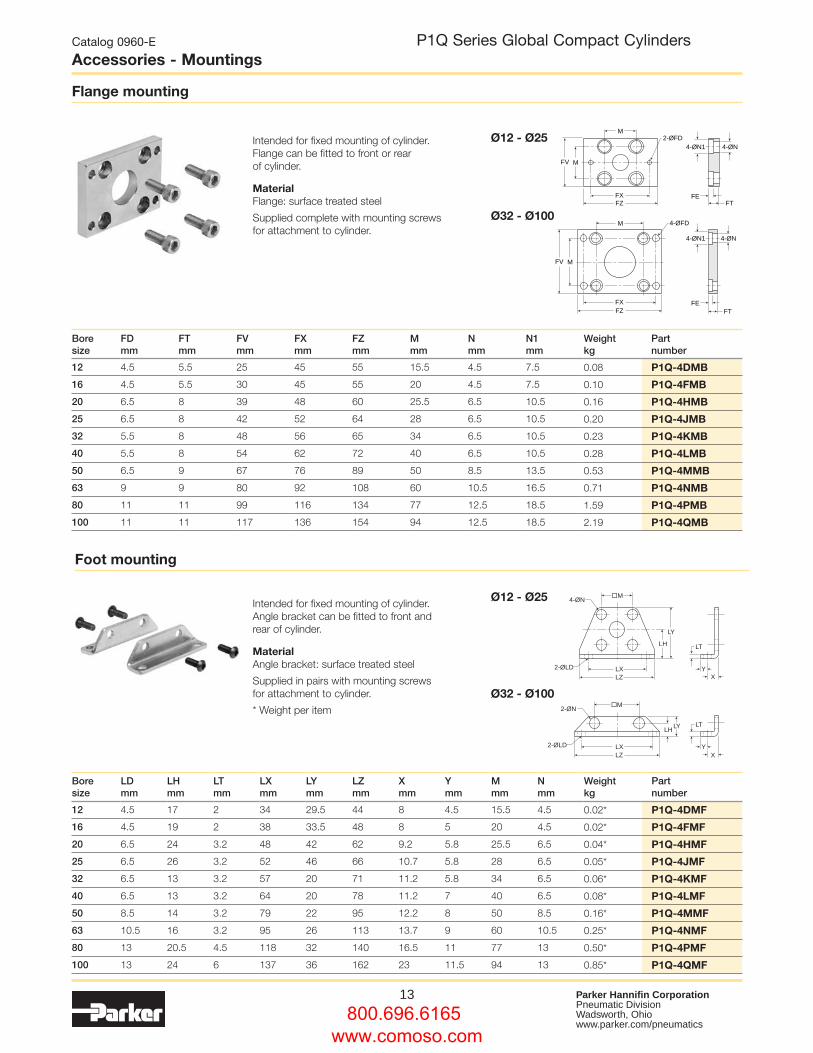
Intended for fixed mounting of cylinder. Flange can be fitted to front or rear of cylinder.
MaterialFlange: surface treated steel
Supplied complete with mounting screws for attachment to cylinder.
Intended for fixed mounting of cylinder. Angle bracket can be fitted to front and rear of cylinder.
MaterialAngle bracket: surface treated steel
Supplied in pairs with mounting screws for attachment to cylinder.
* Weight per item
Flange mounting
Foot mounting
Ø12 - Ø25
Ø12 - Ø25
Ø32 - Ø100
Ø32 - Ø100
XY
LT
LZLX
�M
LY
LH
4-ØN
2-ØLD
XY
LT
LZLX
LYLH
2-ØN
2-ØLD
�M
Bore size
FD mm
FT mm
FV mm
FX mm
FZ mm
M mm
N mm
N1 mm
Weight kg
Part number
12 4.5 5.5 25 45 55 15.5 4.5 7.5 0.08 P1Q-4DMB
16 4.5 5.5 30 45 55 20 4.5 7.5 0.10 P1Q-4FMB
20 6.5 8 39 48 60 25.5 6.5 10.5 0.16 P1Q-4HMB
25 6.5 8 42 52 64 28 6.5 10.5 0.20 P1Q-4JMB
32 5.5 8 48 56 65 34 6.5 10.5 0.23 P1Q-4KMB
40 5.5 8 54 62 72 40 6.5 10.5 0.28 P1Q-4LMB
50 6.5 9 67 76 89 50 8.5 13.5 0.53 P1Q-4MMB
63 9 9 80 92 108 60 10.5 16.5 0.71 P1Q-4NMB
80 11 11 99 116 134 77 12.5 18.5 1.59 P1Q-4PMB
100 11 11 117 136 154 94 12.5 18.5 2.19 P1Q-4QMB
Bore size
LD mm
LH mm
LT mm
LX mm
LY mm
LZ mm
X mm
Y mm
M mm
N mm
Weight kg
Part number
12 4.5 17 2 34 29.5 44 8 4.5 15.5 4.5 0.02* P1Q-4DMF
16 4.5 19 2 38 33.5 48 8 5 20 4.5 0.02* P1Q-4FMF
20 6.5 24 3.2 48 42 62 9.2 5.8 25.5 6.5 0.04* P1Q-4HMF
25 6.5 26 3.2 52 46 66 10.7 5.8 28 6.5 0.05* P1Q-4JMF
32 6.5 13 3.2 57 20 71 11.2 5.8 34 6.5 0.06* P1Q-4KMF
40 6.5 13 3.2 64 20 78 11.2 7 40 6.5 0.08* P1Q-4LMF
50 8.5 14 3.2 79 22 95 12.2 8 50 8.5 0.16* P1Q-4MMF
63 10.5 16 3.2 95 26 113 13.7 9 60 10.5 0.25* P1Q-4NMF
80 13 20.5 4.5 118 32 140 16.5 11 77 13 0.50* P1Q-4PMF
100 13 24 6 137 36 162 23 11.5 94 13 0.85* P1Q-4QMF
FZFX
M
M
4-ØN12-ØFD
4-ØN
FT
FT
FV
FE
FZFX
M
M
4-ØN1
4-ØFD
4-ØN
FV
FE
800.696.6165 www.comoso.com
14 Parker Hannifin CorporationPneumatic DivisionWadsworth, Ohio www.parker.com/pneumatics
Catalog 0960-E
Accessories - MountingsP1Q Series Global Compact Cylinders
CU 4-ØN
ØCD
4-ØN
CW
M
E
ØCD
M E
CZCX
CZCX
RR
CWCU
RR
M E
M E
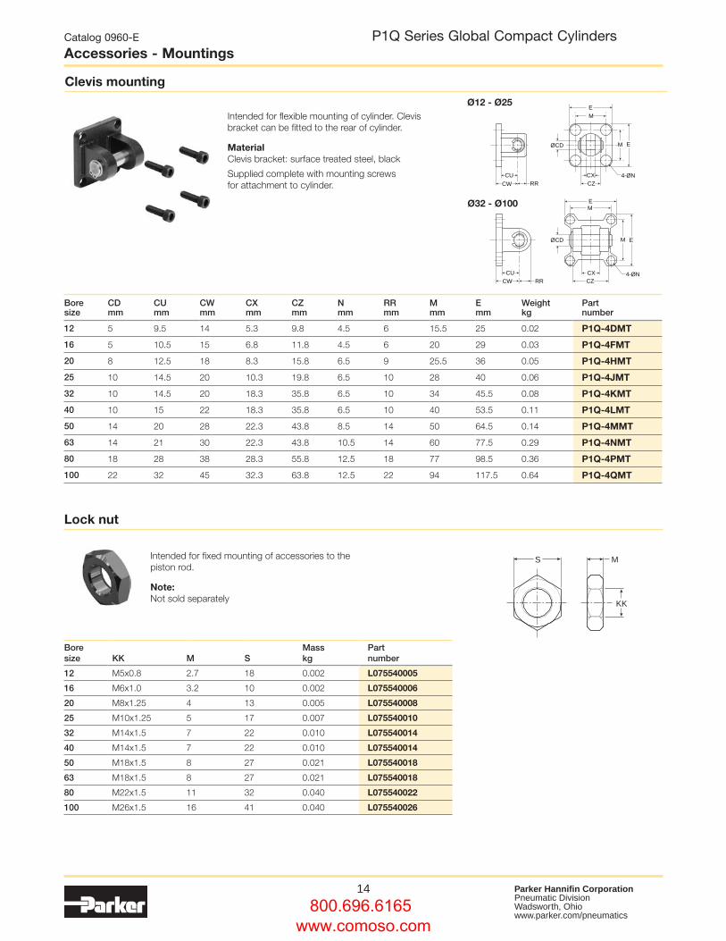
Intended for flexible mounting of cylinder. Clevis bracket can be fitted to the rear of cylinder.
MaterialClevis bracket: surface treated steel, black
Supplied complete with mounting screws for attachment to cylinder.
Clevis mounting
Bore size
CD mm
CU mm
CW mm
CX mm
CZ mm
N mm
RR mm
M mm
E mm
Weight kg
Part number
12 5 9.5 14 5.3 9.8 4.5 6 15.5 25 0.02 P1Q-4DMT
16 5 10.5 15 6.8 11.8 4.5 6 20 29 0.03 P1Q-4FMT
20 8 12.5 18 8.3 15.8 6.5 9 25.5 36 0.05 P1Q-4HMT
25 10 14.5 20 10.3 19.8 6.5 10 28 40 0.06 P1Q-4JMT
32 10 14.5 20 18.3 35.8 6.5 10 34 45.5 0.08 P1Q-4KMT
40 10 15 22 18.3 35.8 6.5 10 40 53.5 0.11 P1Q-4LMT
50 14 20 28 22.3 43.8 8.5 14 50 64.5 0.14 P1Q-4MMT
63 14 21 30 22.3 43.8 10.5 14 60 77.5 0.29 P1Q-4NMT
80 18 28 38 28.3 55.8 12.5 18 77 98.5 0.36 P1Q-4PMT
100 22 32 45 32.3 63.8 12.5 22 94 117.5 0.64 P1Q-4QMT
Ø12 - Ø25
Ø32 - Ø100
Intended for fixed mounting of accessories to the piston rod.
Note:Not sold separately
Lock nut
S M
KK
Bore size KK M S
Mass kg
Part number
12 M5x0.8 2.7 18 0.002 L075540005
16 M6x1.0 3.2 10 0.002 L075540006
20 M8x1.25 4 13 0.005 L075540008
25 M10x1.25 5 17 0.007 L075540010
32 M14x1.5 7 22 0.010 L075540014
40 M14x1.5 7 22 0.010 L075540014
50 M18x1.5 8 27 0.021 L075540018
63 M18x1.5 8 27 0.021 L075540018
80 M22x1.5 11 32 0.040 L075540022
100 M26x1.5 16 41 0.040 L075540026
800.696.6165 www.comoso.com
15 Parker Hannifin CorporationPneumatic DivisionWadsworth, Ohio www.parker.com/pneumatics
Catalog 0960-E
Accessories - MountingsP1Q Series Global Compact Cylinders
KK Th’d x A Depth
EM
ØCKER
LE
CA
E
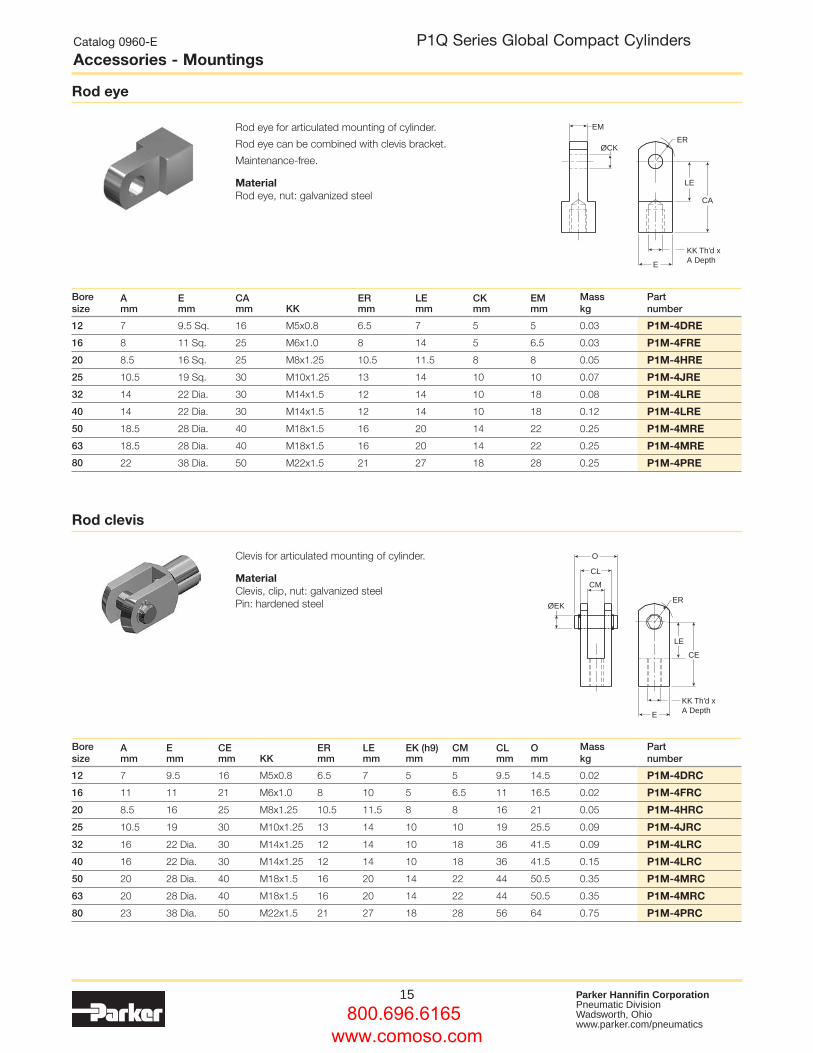
Rod eye for articulated mounting of cylinder.
Rod eye can be combined with clevis bracket.
Maintenance-free.
MaterialRod eye, nut: galvanized steel
Rod eye
Bore size
Amm
Emm
CAmm KK
ERmm
LEmm
CKmm
EMmm
Mass kg
Part number
12 7 9.5 Sq. 16 M5x0.8 6.5 7 5 5 0.03 P1M-4DRE
16 8 11 Sq. 25 M6x1.0 8 14 5 6.5 0.03 P1M-4FRE
20 8.5 16 Sq. 25 M8x1.25 10.5 11.5 8 8 0.05 P1M-4HRE
25 10.5 19 Sq. 30 M10x1.25 13 14 10 10 0.07 P1M-4JRE
32 14 22 Dia. 30 M14x1.5 12 14 10 18 0.08 P1M-4LRE
40 14 22 Dia. 30 M14x1.5 12 14 10 18 0.12 P1M-4LRE
50 18.5 28 Dia. 40 M18x1.5 16 20 14 22 0.25 P1M-4MRE
63 18.5 28 Dia. 40 M18x1.5 16 20 14 22 0.25 P1M-4MRE
80 22 38 Dia. 50 M22x1.5 21 27 18 28 0.25 P1M-4PRE
O
CL
CM
ØEKER
LE
CE
KK Th’d x A DepthE
Clevis for articulated mounting of cylinder.
MaterialClevis, clip, nut: galvanized steel Pin: hardened steel
Rod clevis
Bore size
Amm
Emm
CEmm KK
ERmm
LEmm
EK (h9)mm
CMmm
CLmm
Omm
Mass kg
Part number
12 7 9.5 16 M5x0.8 6.5 7 5 5 9.5 14.5 0.02 P1M-4DRC
16 11 11 21 M6x1.0 8 10 5 6.5 11 16.5 0.02 P1M-4FRC
20 8.5 16 25 M8x1.25 10.5 11.5 8 8 16 21 0.05 P1M-4HRC
25 10.5 19 30 M10x1.25 13 14 10 10 19 25.5 0.09 P1M-4JRC
32 16 22 Dia. 30 M14x1.25 12 14 10 18 36 41.5 0.09 P1M-4LRC
40 16 22 Dia. 30 M14x1.25 12 14 10 18 36 41.5 0.15 P1M-4LRC
50 20 28 Dia. 40 M18x1.5 16 20 14 22 44 50.5 0.35 P1M-4MRC
63 20 28 Dia. 40 M18x1.5 16 20 14 22 44 50.5 0.35 P1M-4MRC
80 23 38 Dia. 50 M22x1.5 21 27 18 28 56 64 0.75 P1M-4PRC
800.696.6165 www.comoso.com
16 Parker Hannifin CorporationPneumatic DivisionWadsworth, Ohio www.parker.com/pneumatics
Catalog 0960-E
Accessories - SensorsP1Q Series Global Compact Cylinders
Global P8S Sensor Series
The P8S family of sensors provides a broad range of reed and solid state sensor types with flying lead or M8 options available. Mounting on all cylinders is within the integrated sensor grooves allowing for compact installation. For 12mm and 16mm bores the sensors can be mounted on 3 sidesand on 20mm to 100mm bores on four sides for flexible mounting and ease of installation.
Electronic sensors
The electronic sensors utilise “Solid State” technology, providing operation with no moving parts. These switches are available in NPN and PNP type, both provide built in short circuit and transient protection as standard. The solid state operation allows for high switching on off frequency, ideal for applications where long service life is required.
Technical dataDesign GMR (Giant Magnetic Resistance)
magneto-resistive function
Installation Mounts within cylinder switch Groove
Outputs PNP or NPN, normally open
Voltage range 5-30 V DC
Voltage drop 1.5 V max
Switching Current 50 mA max
Switch Rating 1.5 W max
Leakage current 0.01 mA max
Internal consumption 10 mA max (NPN) 12 mA max (PNP)
On/off switching frequency 1000 Hz max
Encapsulation IP67 (NEMA 6)
Temperature range –10 °C to +70 °C
Indication LED Red (NPN)
LED Green (PNP)
Cable Polyurethane
Reed sensors
Reed type sensors are based on proven reed switch technology and provide reliable function in many applications. Simple installation and the available AC voltage range are advantages for this range of sensors.
Technical dataDesign Reed element
Installation Mounts within cylinder switch Groove
Output Normally open
Voltage range 5-120 V DC/AC
Voltage Drop 2.5 V max
Switching Current 100 mA max
Switch Rating 10 W max
Encapsulation IP67 (NEMA 6)
Temperature range –10 °C to +70 °C
Indication LED Red
Cable Polyurethane
800.696.6165 www.comoso.com
17 Parker Hannifin CorporationPneumatic DivisionWadsworth, Ohio www.parker.com/pneumatics
Catalog 0960-E
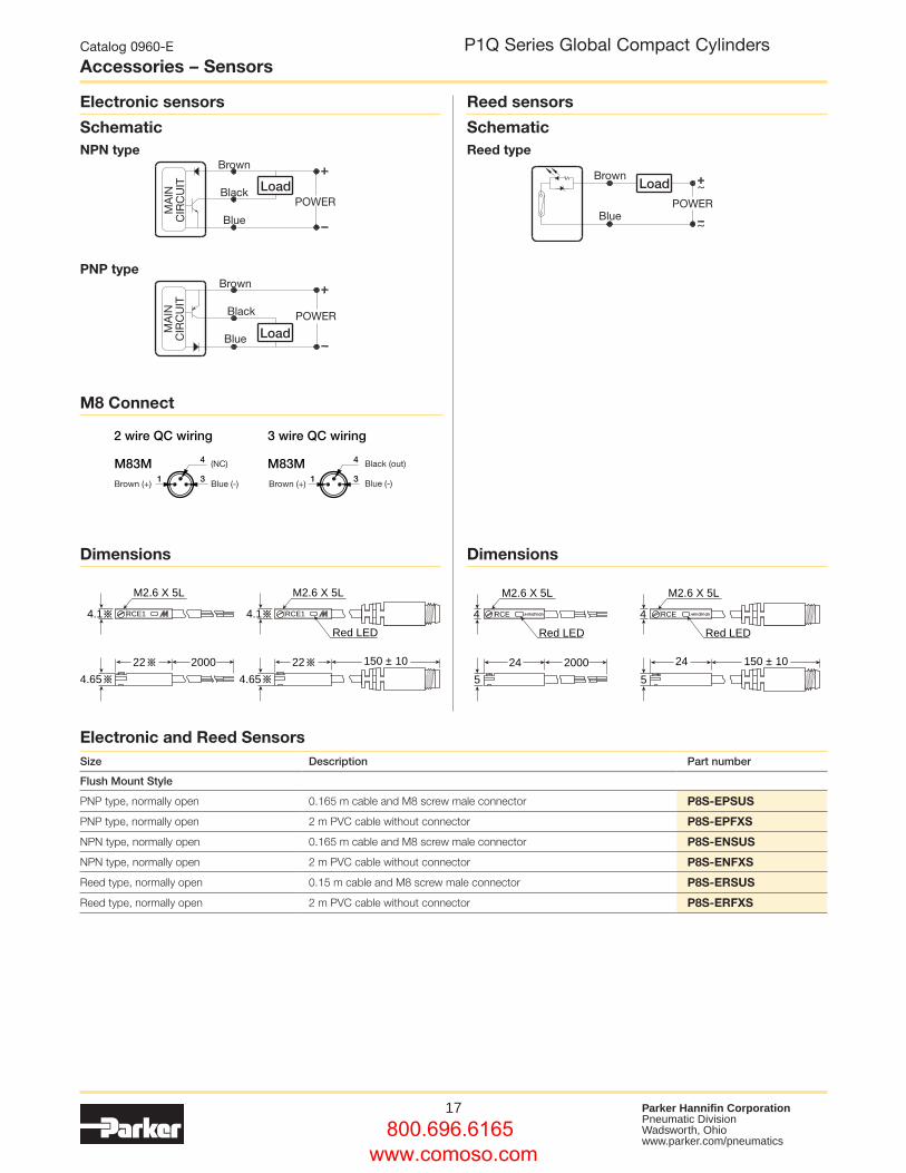
Accessories – SensorsP1Q Series Global Compact Cylinders
Dimensions Dimensions
Schematic
M8 Connect
Schematic
Electronic sensors Reed sensors
LoadBrown
BluePOWER
Load
Load
Brown
Black
Blue
Brown
Black
Blue
MA
INC
IRC
UIT
MA
INC
IRC
UIT
POWER
POWER
NPN type Reed type
PNP type
RCE1
M2.6 X 5L
200022
4.1
4.65
RCE1
M2.6 X 5L
Red LED
22
4.1
4.65
150 ± 10
RCE
M2.6 X 5L
Red LED
200024
4
5
RCE
M2.6 X 5L
Red LED
24 150 ± 10
4
5
2 wire QC wiring 3 wire QC wiring
M83M1 3
4
M124M
3 1
2
4
1 3
4M83M
3 1
2
4
M124M
(NC)
(NC)
Brown (+)
(NC)
Black (out)
Black (out)
Brown (+)
Blue (-)Brown (+)
Blue (-)
Brown (+)
Blue (-)
(NC)
Blue (-)
Electronic and Reed SensorsSize Description Part number
Flush Mount Style
PNP type, normally open 0.165 m cable and M8 screw male connector P8S-EPSUS
PNP type, normally open 2 m PVC cable without connector P8S-EPFXS
NPN type, normally open 0.165 m cable and M8 screw male connector P8S-ENSUS
NPN type, normally open 2 m PVC cable without connector P8S-ENFXS
Reed type, normally open 0.15 m cable and M8 screw male connector P8S-ERSUS
Reed type, normally open 2 m PVC cable without connector P8S-ERFXS
800.696.6165 www.comoso.com
18 Parker Hannifin CorporationPneumatic DivisionWadsworth, Ohio www.parker.com/pneumatics
Catalog 0960-E
Air Quality ChartP1Q Series Global Compact Cylinders
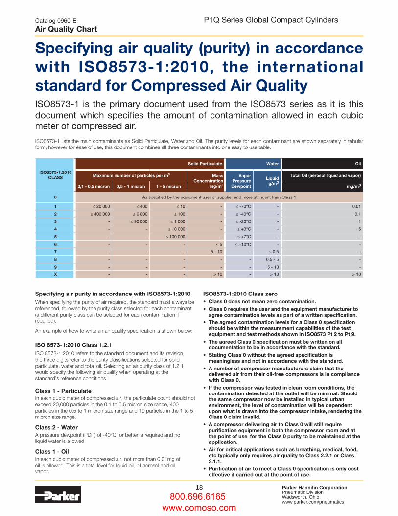
Specifying air quality (purity) in accordance with ISO8573-1:2010, the international standard for Compressed Air QualityISO8573-1 is the primary document used from the ISO8573 series as it is this document which specifies the amount of contamination allowed in each cubic meter of compressed air.
ISO8573-1 lists the main contaminants as Solid Particulate, Water and Oil. The purity levels for each contaminant are shown separately in tabular form, however for ease of use, this document combines all three contaminants into one easy to use table.
ISO8573-1:2010 CLASS
Solid Particulate Water Oil
Maximum number of particles per m3 MassConcentration
mg/m3
Vapor Pressure
Dewpoint
Liquid g/m3
Total Oil (aerosol liquid and vapor)
0,1 - 0,5 micron 0,5 - 1 micron 1 - 5 micron mg/m3
0 As specified by the equipment user or supplier and more stringent than Class 1
1 ≤ 20 000 ≤ 400 ≤ 10 - ≤ -70°C - 0.01
2 ≤ 400 000 ≤ 6 000 ≤ 100 - ≤ -40°C - 0.1
3 - ≤ 90 000 ≤ 1 000 - ≤ -20°C - 1
4 - - ≤ 10 000 - ≤ +3°C - 5
5 - - ≤ 100 000 - ≤ +7°C - -
6 - - - ≤ 5 ≤ +10°C - -
7 - - - 5 - 10 - ≤ 0,5 -
8 - - - - - 0.5 - 5 -
9 - - - - - 5 - 10 -
X - - - > 10 - > 10 > 10
Specifying air purity in accordance with ISO8573-1:2010When specifying the purity of air required, the standard must always be referenced, followed by the purity class selected for each contaminant (a different purity class can be selected for each contamination if required).
An example of how to write an air quality specification is shown below:
ISO 8573-1:2010 Class 1.2.1ISO 8573-1:2010 refers to the standard document and its revision, the three digits refer to the purity classifications selected for solid particulate, water and total oil. Selecting an air purity class of 1.2.1 would specify the following air quality when operating at the standard’s reference conditions :
Class 1 - ParticulateIn each cubic meter of compressed air, the particulate count should not exceed 20,000 particles in the 0.1 to 0.5 micron size range, 400 particles in the 0.5 to 1 micron size range and 10 particles in the 1 to 5 micron size range.
Class 2 - WaterA pressure dewpoint (PDP) of -40°C or better is required and no liquid water is allowed.
Class 1 - OilIn each cubic meter of compressed air, not more than 0.01mg of oil is allowed. This is a total level for liquid oil, oil aerosol and oil vapor.
ISO8573-1:2010 Class zero • Class 0 does not mean zero contamination.• Class 0 requires the user and the equipment manufacturer to
agree contamination levels as part of a written specification. • The agreed contamination levels for a Class 0 specification
should be within the measurement capabilities of the test equipment and test methods shown in ISO8573 Pt 2 to Pt 9.
• The agreed Class 0 specification must be written on all documentation to be in accordance with the standard.
• Stating Class 0 without the agreed specification is meaningless and not in accordance with the standard.
• A number of compressor manufacturers claim that the delivered air from their oil-free compressors is in compliance with Class 0.
• If the compressor was tested in clean room conditions, the contamination detected at the outlet will be minimal. Should the same compressor now be installed in typical urban environment, the level of contamination will be dependent upon what is drawn into the compressor intake, rendering the Class 0 claim invalid.
• A compressor delivering air to Class 0 will still require purification equipment in both the compressor room and at the point of use for the Class 0 purity to be maintained at the application.
• Air for critical applications such as breathing, medical, food, etc typically only requires air quality to Class 2.2.1 or Class 2.1.1.
• Purification of air to meet a Class 0 specification is only cost effective if carried out at the point of use.
800.696.6165 www.comoso.com
19 Parker Hannifin CorporationPneumatic DivisionWadsworth, Ohio www.parker.com/pneumatics
Catalog 0960-E
NotesP1Q Series Global Compact Cylinders
800.696.6165 www.comoso.com

20 Parker Hannifin CorporationPneumatic DivisionWadsworth, Ohio www.parker.com/pneumatics
P1Q Series Global Compact Cylinders Catalog 0960-E
Safety Guide
Before selecting or using Parker (The Company) cylinders or related accessories, it is important that you read, understand and follow the following safety information. Training is advised before selecting and using The Company’s products.1.0 General Instructions 1.1 Scope – This safety guide provides instructions for selecting
and using (including assembling, installing, and maintaining) cylinder products. This safety guide is a supplement to and is to be used with the specific Company publications for the specific cylinder products that are being considered for use.
1.2 Fail Safe – Cylinder products can and do fail without warning for many reasons. All systems and equipment should be designed in a fail-safe mode so that if the failure of a cylinder product occurs people and property won’t be endangered.
1.3 Distribution – Provide a free copy of this safety guide to each person responsible for selecting or using cylinder products. Do not select or use The Company’s cylinders without thoroughly reading and understanding this safety guide as well as the specific Company publications for the products considered or selected.
1.4 User Responsibility – Due to very wide variety of cylinder applications and cylinder operating conditions, The Company does not warrant that any particular cylinder is suitable for any specific application. This safety guide does not analyze all technical parameters that must be considered in selecting a product. The hydraulic and pneumatic cylinders outlined in this catalog are designed to The Company’s design guidelines and do not necessarily meet the design guideline of other agencies such as American Bureau of Shipping, ASME Pressure Vessel Code etc. The user, through its own analysis and testing, is solely responsible for:
• Making the final selection of the cylinders and related accessories. • Determining if the cylinders are required to meet specific design
requirements as required by the Agency(s) or industry standards covering the design of the user’s equipment.
• Assuring that the user’s requirements are met, OSHA requirements are met, and safety guidelines from the applicable agencies such as but not limited to ANSI are followed and that the use presents no health or safety hazards.
• Providing all appropriate health and safety warnings on the equipment on which the cylinders are used.
1.5 Additional Questions – Call the appropriate Company technical service department if you have any questions or require any additional information. See the Company publication for the product being considered or used, or call 1-800-CPARKER, or go to www.parker.com, for telephone numbers of the appropriate technical service department.
2.0 Cylinder and Accessories Selection 2.1 Seals – Part of the process of selecting a cylinder is the selection
of seal compounds. Before making this selection, consult the “seal information page(s)” of the publication for the series of cylinders of interest.
The application of cylinders may allow fluids such as cutting fluids, wash down fluids etc. to come in contact with the external area of the cylinder. These fluids may attack the piston rod wiper and or the primary seal and must be taken into account when selecting and specifying seal compounds.
Dynamic seals will wear. The rate of wear will depend on many operating factors. Wear can be rapid if a cylinder is mis-aligned or if the cylinder has been improperly serviced. The user must take seal wear into consideration in the application of cylinders.
2.2 Piston Rods – Possible consequences of piston rod failure orseparation of the piston rod from the piston include, but are not limited to are:
• Piston rod and or attached load thrown off at high speed. • High velocity fluid discharge. • Piston rod extending when pressure is applied in the piston
retract mode. Piston rods or machine members attached to the piston rod may move
suddenly and without warning as a consequence of other conditions occurring to the machine such as, but not limited to:
• Unexpected detachment of the machine member from the piston rod. • Failure of the pressurized fluid delivery system (hoses, fittings, valves,
pumps, compressors) which maintain cylinder position. • Catastrophic cylinder seal failure leading to sudden loss of pressurized
fluid. • Failure of the machine control system. Follow the recommendations of the “Piston Rod Selection Chart and
Data” in the publication for the series of cylinders of interest. The suggested piston rod diameter in these charts must be followed in order to avoid piston rod buckling.
Piston rods are not normally designed to absorb bending moments or loads which are perpendicular to the axis of piston rod motion. These additional loads can cause the piston rod to fail. If these types of additional loads are expected to be imposed on the piston rod, their magnitude should be made known to our engineering department.
The cylinder user should always make sure that the piston rod is securely attached to the machine member.
On occasion cylinders are ordered with double rods (a piston rod extended from both ends of the cylinder). In some cases a stop is threaded on to one of the piston rods and used as an external stroke adjuster. On occasions spacers are attached to the machine member connected to the piston rod and also used as a stroke adjuster. In both cases the stops will create a pinch point and the user should consider appropriate use of guards. If these external stops are not perpendicular to the mating contact surface, or if debris is trapped between the contact surfaces, a bending moment will be placed on the piston rod, which can lead to piston rod failure. An external stop will also negate the effect of cushioning and will subject the piston rod to impact loading. Those two (2) conditions can cause piston rod failure. Internal stroke adjusters are available with and without cushions. The use of external stroke adjusters should be reviewed with our engineering department.
The piston rod to piston and the stud to piston rod threaded connections are secured with an anaerobic adhesive. The strength of the adhesive decreases with increasing temperature. Cylinders which can be exposed to temperatures above +250°F (+121°C) are to be ordered with a non studded piston rod and a pinned piston to rod joint.
2.3 Cushions – Cushions should be considered for cylinder applications when the piston velocity is expected to be over 4 inches/second.
Cylinder cushions are normally designed to absorb the energy of a linear applied load. A rotating mass has considerably more energy than the same mass moving in a linear mode. Cushioning for a rotating mass application should be review by our engineering department.
2.4 Cylinder Mountings – Some cylinder mounting configurations may have certain limitations such as but not limited to minimum stroke for side or foot mounting cylinders or pressure de-ratings for certain mounts. Carefully review the catalog for these types of restrictions.
Always mount cylinders using the largest possible high tensile alloy steel socket head cap screws that can fit in the cylinder mounting holes and torque them to the manufacturer’s recommendations for their size.
2.5 Port Fittings – Hydraulic cylinders applied with meter out or deceleration circuits are subject to intensified pressure at piston rod end.
The rod end pressure is approximately equal to: operating pressure x effective cap end area
effective rod end piston area Contact your connector supplier for the pressure rating of individual
connectors.
3.0 Cylinder and Accessories Installation and Mounting 3.1 Installation 3.1.1 – Cleanliness is an important consideration, and cylinders are
shipped with the ports plugged to protect them from contaminants entering the ports. These plugs should not be removed until the piping is to be installed. Before making the connection to the cylinder ports, piping should be thoroughly cleaned to remove all chips or burrs which might have resulted from threading or flaring operations.
Safety Guide for Selecting and Using Hydraulic, Pneumatic Cylinders and Their Accessories
WARNING: FAILURE OF THE CyLINDER, ITS PARTS, ITS MOUNTING, ITS CONNECTIONS TO OTHER OBJECTS, OR ITS CONTROLS CAN RESULT IN: • Unanticipated or uncontrolled movement of the cylinder or objects connected to it. • Falling of the cylinder or objects held up by it. • Fluid escaping from the cylinder, potentially at high velocity.THESE EVENTS COULD CAUSE DEATH OR PERSONAL INJURy By, FOR EXAMPLE, PERSONS FALLING FROM HIGH LOCATIONS, BEING CRUSHED OR STRUCK By HEAVy OR FAST MOVING OBJECTS, BEING PUSHED INTO DANGEROUS EQUIPMENT OR SITUATIONS, OR SLIPPING ON ESCAPED FLUID.
!
800.696.6165 www.comoso.com
21 Parker Hannifin CorporationPneumatic DivisionWadsworth, Ohio www.parker.com/pneumatics
P1Q Series Global Compact Cylinders Catalog 0960-E
Safety Guide
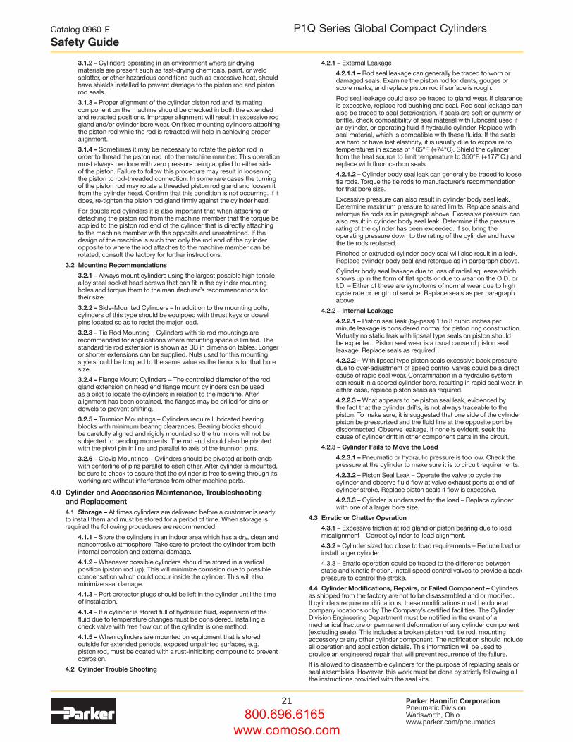
3.1.2 – Cylinders operating in an environment where air drying materials are present such as fast-drying chemicals, paint, or weld splatter, or other hazardous conditions such as excessive heat, should have shields installed to prevent damage to the piston rod and piston rod seals.
3.1.3 – Proper alignment of the cylinder piston rod and its mating component on the machine should be checked in both the extended and retracted positions. Improper alignment will result in excessive rod gland and/or cylinder bore wear. On fixed mounting cylinders attaching the piston rod while the rod is retracted will help in achieving proper alignment.
3.1.4 – Sometimes it may be necessary to rotate the piston rod in order to thread the piston rod into the machine member. This operation must always be done with zero pressure being applied to either side of the piston. Failure to follow this procedure may result in loosening the piston to rod-threaded connection. In some rare cases the turning of the piston rod may rotate a threaded piston rod gland and loosen it from the cylinder head. Confirm that this condition is not occurring. If it does, re-tighten the piston rod gland firmly against the cylinder head.
For double rod cylinders it is also important that when attaching or detaching the piston rod from the machine member that the torque be applied to the piston rod end of the cylinder that is directly attaching to the machine member with the opposite end unrestrained. If the design of the machine is such that only the rod end of the cylinder opposite to where the rod attaches to the machine member can be rotated, consult the factory for further instructions.
3.2 Mounting Recommendations
3.2.1 – Always mount cylinders using the largest possible high tensile alloy steel socket head screws that can fit in the cylinder mounting holes and torque them to the manufacturer’s recommendations for their size.
3.2.2 – Side-Mounted Cylinders – In addition to the mounting bolts, cylinders of this type should be equipped with thrust keys or dowel pins located so as to resist the major load.
3.2.3 – Tie Rod Mounting – Cylinders with tie rod mountings are recommended for applications where mounting space is limited. The standard tie rod extension is shown as BB in dimension tables. Longer or shorter extensions can be supplied. Nuts used for this mounting style should be torqued to the same value as the tie rods for that bore size.
3.2.4 – Flange Mount Cylinders – The controlled diameter of the rod gland extension on head end flange mount cylinders can be used as a pilot to locate the cylinders in relation to the machine. After alignment has been obtained, the flanges may be drilled for pins or dowels to prevent shifting.
3.2.5 – Trunnion Mountings – Cylinders require lubricated bearing blocks with minimum bearing clearances. Bearing blocks should be carefully aligned and rigidly mounted so the trunnions will not be subjected to bending moments. The rod end should also be pivoted with the pivot pin in line and parallel to axis of the trunnion pins.
3.2.6 – Clevis Mountings – Cylinders should be pivoted at both ends with centerline of pins parallel to each other. After cylinder is mounted, be sure to check to assure that the cylinder is free to swing through its working arc without interference from other machine parts.
4.0 Cylinder and Accessories Maintenance, Troubleshooting and Replacement
4.1 Storage – At times cylinders are delivered before a customer is ready to install them and must be stored for a period of time. When storage is required the following procedures are recommended.
4.1.1 – Store the cylinders in an indoor area which has a dry, clean and noncorrosive atmosphere. Take care to protect the cylinder from both internal corrosion and external damage.
4.1.2 – Whenever possible cylinders should be stored in a vertical position (piston rod up). This will minimize corrosion due to possible condensation which could occur inside the cylinder. This will also minimize seal damage.
4.1.3 – Port protector plugs should be left in the cylinder until the time of installation.
4.1.4 – If a cylinder is stored full of hydraulic fluid, expansion of the fluid due to temperature changes must be considered. Installing a check valve with free flow out of the cylinder is one method.
4.1.5 – When cylinders are mounted on equipment that is stored outside for extended periods, exposed unpainted surfaces, e.g. piston rod, must be coated with a rust-inhibiting compound to prevent corrosion.
4.2 Cylinder Trouble Shooting
4.2.1 – External Leakage
4.2.1.1 – Rod seal leakage can generally be traced to worn or damaged seals. Examine the piston rod for dents, gouges or score marks, and replace piston rod if surface is rough.
Rod seal leakage could also be traced to gland wear. If clearance is excessive, replace rod bushing and seal. Rod seal leakage can also be traced to seal deterioration. If seals are soft or gummy or brittle, check compatibility of seal material with lubricant used if air cylinder, or operating fluid if hydraulic cylinder. Replace with seal material, which is compatible with these fluids. If the seals are hard or have lost elasticity, it is usually due to exposure to temperatures in excess of 165°F. (+74°C). Shield the cylinder from the heat source to limit temperature to 350°F. (+177°C.) and replace with fluorocarbon seals.
4.2.1.2 – Cylinder body seal leak can generally be traced to loose tie rods. Torque the tie rods to manufacturer’s recommendation for that bore size.
Excessive pressure can also result in cylinder body seal leak. Determine maximum pressure to rated limits. Replace seals and retorque tie rods as in paragraph above. Excessive pressure can also result in cylinder body seal leak. Determine if the pressure rating of the cylinder has been exceeded. If so, bring the operating pressure down to the rating of the cylinder and have the tie rods replaced.
Pinched or extruded cylinder body seal will also result in a leak. Replace cylinder body seal and retorque as in paragraph above.
Cylinder body seal leakage due to loss of radial squeeze which shows up in the form of flat spots or due to wear on the O.D. or I.D. – Either of these are symptoms of normal wear due to high cycle rate or length of service. Replace seals as per paragraph above.
4.2.2 – Internal Leakage
4.2.2.1 – Piston seal leak (by-pass) 1 to 3 cubic inches per minute leakage is considered normal for piston ring construction. Virtually no static leak with lipseal type seals on piston should be expected. Piston seal wear is a usual cause of piston seal leakage. Replace seals as required.
4.2.2.2 – With lipseal type piston seals excessive back pressure due to over-adjustment of speed control valves could be a direct cause of rapid seal wear. Contamination in a hydraulic system can result in a scored cylinder bore, resulting in rapid seal wear. In either case, replace piston seals as required.
4.2.2.3 – What appears to be piston seal leak, evidenced by the fact that the cylinder drifts, is not always traceable to the piston. To make sure, it is suggested that one side of the cylinder piston be pressurized and the fluid line at the opposite port be disconnected. Observe leakage. If none is evident, seek the cause of cylinder drift in other component parts in the circuit.
4.2.3 – Cylinder Fails to Move the Load
4.2.3.1 – Pneumatic or hydraulic pressure is too low. Check the pressure at the cylinder to make sure it is to circuit requirements.
4.2.3.2 – Piston Seal Leak – Operate the valve to cycle the cylinder and observe fluid flow at valve exhaust ports at end of cylinder stroke. Replace piston seals if flow is excessive.
4.2.3.3 – Cylinder is undersized for the load – Replace cylinder with one of a larger bore size.
4.3 Erratic or Chatter Operation
4.3.1 – Excessive friction at rod gland or piston bearing due to load misalignment – Correct cylinder-to-load alignment.
4.3.2 – Cylinder sized too close to load requirements – Reduce load or install larger cylinder.
4.3.3 – Erratic operation could be traced to the difference between static and kinetic friction. Install speed control valves to provide a back pressure to control the stroke.
4.4 Cylinder Modifications, Repairs, or Failed Component – Cylindersas shipped from the factory are not to be disassembled and or modified. If cylinders require modifications, these modifications must be done at company locations or by The Company’s certified facilities. The Cylinder Division Engineering Department must be notified in the event of a mechanical fracture or permanent deformation of any cylinder component (excluding seals). This includes a broken piston rod, tie rod, mounting accessory or any other cylinder component. The notification should include all operation and application details. This information will be used to provide an engineered repair that will prevent recurrence of the failure.
It is allowed to disassemble cylinders for the purpose of replacing seals or seal assemblies. However, this work must be done by strictly following all the instructions provided with the seal kits.
800.696.6165 www.comoso.com
22 Parker Hannifin CorporationPneumatic DivisionWadsworth, Ohio www.parker.com/pneumatics
1. Terms and Conditions. Seller’s willingness to offer Products, or accept an order for Products, to or from Buyer is subject to these Terms and Conditions or any newer version of the terms and conditions found on-line at www.parker.com/saleterms/. Seller objects to any contrary or additional terms or conditions of Buyer’s order or any other document issued by Buyer.2. Price Adjustments; Payments. Prices stated on Seller’s quote or other documentation offered by Seller are valid for 30 days, and do not include any sales, use, or other taxes unless specifically stated, Unless otherwise specified by Seller, all prices are F.C.A. Seller’s facility (INCOTERMS 2010). Payment is subject to credit approval and is due 30 days from the date of invoice or such other term as required by Seller’s Credit Department, after which Buyer shall pay interest on any unpaid invoices at the rate of 1.5% per month or the maximum allowable rate under applicable law.3. Delivery Dates; Title and Risk; Shipment. All delivery dates are approximate and Seller shall not be responsible for any damages resulting from any delay. Regardless of the manner of shipment, title to any products and risk of loss or damage shall pass to Buyer upon placement of the products with the shipment carrier at Seller’s facility. Unless otherwise stated, Seller may exercise its judgment in choosing the carrier and means of delivery. No deferment of shipment at Buyers’ request beyond the respective dates indicated will be made except on terms that will indemnify, defend and hold Seller harmless against all loss and additional expense. Buyer shall be responsible for any additional shipping charges incurred by Seller due to Buyer’s acts or omissions.4. Warranty. Seller warrants that the Products sold hereunder shall be free from defects in material or workmanship for a period of twelve months from the date of delivery to Buyer or 2,000 hours of normal use, whichever occurs first. The prices charged for Seller’s products are based upon the exclusive limited warranty stated above, and upon the following disclaimer: DISCLAIMER OF WARRANTy: THIS WARRANTY COMPRISES THE SOLE AND ENTIRE WARRANTY PERTAINING TO PRODUCTS PROVIDED HEREUNDER. SELLER DISCLAIMS ALL OTHER WARRANTIES, EXPRESS AND IMPLIED, INCLUDING DESIGN, MERCHANTABILITY AND FITNESS FOR A PARTICULAR PURPOSE.5. Claims; Commencement of Actions. Buyer shall promptly inspect all Products upon delivery. No claims for shortages will be allowed unless reported to the Seller within 10 days of delivery. No other claims against Seller will be allowed unless asserted in writing within 30 days after delivery. Buyer shall notify Seller of any alleged breach of warranty within 30 days after the date the defect is or should have been discovered by Buyer. Any action based upon breach of this agreement or upon any other claim arising out of this sale (other than an action by Seller for an amount due on any invoice) must be commenced within 12 months from the date of the breach without regard to the date breach is discovered.6. LIMITATION OF LIABILITY. UPON NOTIFICATION, SELLER WILL, AT ITS OPTION, REPAIR OR REPLACE A DEFECTIVE PRODUCT, OR REFUND THE PURCHASE PRICE. IN NO EVENT SHALL SELLER BE LIABLE TO BUYER FOR ANY SPECIAL, INDIRECT, INCIDENTAL OR CONSEQUENTIAL DAMAGES ARISING OUT OF, OR AS THE RESULT OF, THE SALE, DELIVERY, NON-DELIVERY, SERVICING, USE OR LOSS OF USE OF THE PRODUCTS OR ANY PART THEREOF, OR FOR ANY CHARGES OR EXPENSES OF ANY NATURE INCURRED WITHOUT SELLER’S WRITTEN CONSENT, EVEN IF SELLER HAS BEEN NEGLIGENT, WHETHER IN CONTRACT, TORT OR OTHER LEGAL THEORY. IN NO EVENT SHALL SELLER’S LIABILITY UNDER ANY CLAIM MADE BY BUYER EXCEED THE PURCHASE PRICE OF THE PRODUCTS.7. User Responsibility. The user, through its own analysis and testing, is solely responsible for making the final selection of the system and Product and assuring that all performance, endurance, maintenance, safety and warning requirements of the application are met. The user must analyze all aspects of the application and follow applicable industry standards and Product information. If Seller provides Product or system options, the user is responsible for determining that such data and specifications are suitable and sufficient for all applications and reasonably foreseeable uses of the Products or systems.8. Loss to Buyer’s Property. Any designs, tools, patterns, materials, drawings, confidential information or equipment furnished by Buyer or any other items which become Buyer’s property, may be considered obsolete and may be destroyed by Seller after two consecutive years have elapsed without Buyer ordering the items manufactured using such property. Seller shall not be responsible for any loss or damage to such property while it is in Seller’s possession or control.9. Special Tooling. A tooling charge may be imposed for any special tooling, including without limitation, dies, fixtures, molds and patterns, acquired to manufacture Products. Such special tooling shall be and remain Seller’s property notwithstanding payment of any charges by Buyer. In no event will Buyer acquire any interest in apparatus belonging to Seller which is utilized in the manufacture of the Products, even if such apparatus has been specially converted or adapted for such manufacture and notwithstanding any charges paid by Buyer. Unless otherwise agreed, Seller shall have the right to alter, discard or otherwise dispose of any special tooling or other property in its sole discretion at any time.10. Buyer’s Obligation; Rights of Seller. To secure payment of all sums due or otherwise, Seller shall retain a security interest in the goods delivered and this agreement shall be deemed a Security Agreement under the Uniform Commercial Code. Buyer authorizes Seller as its attorney to execute and file on Buyer’s behalf all documents Seller deems necessary to perfect its security interest.11. Improper use and Indemnity. Buyer shall indemnify, defend, and hold Seller harmless from any claim, liability, damages, lawsuits, and costs (including attorney fees), whether for personal injury, property damage, patent, trademark or copyright
The items described in this document and other documents and descriptions provided by Parker Hannifin Corporation, its subsidiaries and its authorized distributors (“Seller”) are hereby offered for sale at prices to be established by Seller. This offer and its acceptance by any customer (“Buyer”) shall be governed by all of the following Terms and Conditions. Buyer’s order for any item described in its document, when communicated to Seller verbally, or in writing, shall constitute acceptance of this offer. All goods or work described will be referred to as “Products”.
infringement or any other claim, brought by or incurred by Buyer, Buyer’s employees, or any other person, arising out of: (a) improper selection, improper application or other misuse of Products purchased by Buyer from Seller; (b) any act or omission, negligent or otherwise, of Buyer; (c) Seller’s use of patterns, plans, drawings, or specifications furnished by Buyer to manufacture Product; or (d) Buyer’s failure to comply with these terms and conditions. Seller shall not indemnify Buyer under any circumstance except as otherwise provided.12. Cancellations and Changes. Orders shall not be subject to cancellation or change by Buyer for any reason, except with Seller’s written consent and upon terms that will indemnify, defend and hold Seller harmless against all direct, incidental and consequential loss or damage. Seller may change product features, specifications, designs and availability with notice to Buyer.13. Limitation on Assignment. Buyer may not assign its rights or obligations under this agreement without the prior written consent of Seller.14. Force Majeure. Seller does not assume the risk and shall not be liable for delay or failure to perform any of Seller’s obligations by reason of circumstances beyond the reasonable control of Seller (hereinafter “Events of Force Majeure”) Events of Force Majeure shall include without limitation: accidents, strikes or labor disputes, acts of any government or government agency, acts of nature, delays or failures in delivery from carriers or suppliers, shortages of materials, or any other cause beyond Seller’s reasonable control.15. Waiver and Severability. Failure to enforce any provision of this agreement will not waive that provision nor will any such failure prejudice Seller’s right to enforce that provision in the future. Invalidation of any provision of this agreement by legislation or other rule of law shall not invalidate any other provision herein. The remaining provisions of this agreement will remain in full force and effect.16. Termination. Seller may terminate this agreement for any reason and at any time by giving Buyer thirty (30) days written notice of termination. Seller may immediately terminate this agreement, in writing, if Buyer: (a) commits a breach of any provision of this agreement (b) appointments a trustee, receiver or custodian for all or any part of Buyer’s property (c) files a petition for relief in bankruptcy on its own behalf, or by a third party (d) makes an assignment for the benefit of creditors, or (e) the dissolves or liquidates all or a majority of its assets.17. Governing Law. This agreement and the sale and delivery of all Products hereunder shall be deemed to have taken place in and shall be governed and construed in accordance with the laws of the State of Ohio, as applicable to contracts executed and wholly performed therein and without regard to conflicts of laws principles. Buyer irrevocably agrees and consents to the exclusive jurisdiction and venue of the courts of Cuyahoga County, Ohio with respect to any dispute, controversy or claim arising out of or relating to this agreement. 18. Indemnity for Infringement of Intellectual Property Rights. Seller shall have no liability for infringement of any patents, trademarks, copyrights, trade dress, trade secrets or similar rights except as provided in this Section. Seller will defend and indemnify Buyer against allegations of infringement of U.S. patents, U.S. trademarks, copyrights, trade dress and trade secrets (“Intellectual Property Rights”). Seller will defend at its expense and will pay the cost of any settlement or damages awarded in an action brought against Buyer based on an allegation that a Product sold pursuant to this Agreement infringes the Intellectual Property Rights of a third party. Seller’s obligation to defend and indemnify Buyer is contingent on Buyer notifying Seller within ten (10) days after Buyer becomes aware of such allegations of infringement, and Seller having sole control over the defense of any allegations or actions including all negotiations for settlement or compromise. If a Product is subject to a claim that it infringes the Intellectual Property Rights of a third party, Seller may, at its sole expense and option, procure for Buyer the right to continue using the Product, replace or modify the Product so as to make it noninfringing, or offer to accept return of the Product and return the purchase price less a reasonable allowance for depreciation. Notwithstanding the foregoing, Seller shall have no liability for claims of infringement based on information provided by Buyer, or directed to Products delivered hereunder for which the designs are specified in whole or part by Buyer, or infringements resulting from the modification, combination or use in a system of any Product sold hereunder. The foregoing provisions of this Section shall constitute Seller’s sole and exclusive liability and Buyer’s sole and exclusive remedy for infringement of Intellectual Property Rights.19. Entire Agreement. This agreement contains the entire agreement between the Buyer and Seller and constitutes the final, complete and exclusive expression of the terms of sale. All prior or contemporaneous written or oral agreements or negotiations with respect to the subject matter are herein merged.20. Compliance with Law, U. K. Bribery Act and U.S. Foreign Corrupt Practices Act. Buyer agrees to comply with all applicable laws and regulations, including both those of the United Kingdom and the United States of America, and of the country or countries of the Territory in which the Buyer may operate, including without limitation the U. K. Bribery Act, the U.S. Foreign Corrupt Practices Act (“FCPA”) and the U.S. Anti-Kickback Act (the “Anti-Kickback Act”), and agrees to indemnify and hold harmless Seller from the consequences of any violation of such provisions by Buyer, its employees or agents. Buyer acknowledges that they are familiar with the provisions of the U. K. Bribery Act, the FCPA and the Anti-Kickback Act, and certifies that Buyer will adhere to the requirements thereof. In particular, Buyer represents and agrees that Buyer shall not make any payment or give anything of value, directly or indirectly to any governmental official, any foreign political party or official thereof, any candidate for foreign political office, or any commercial entity or person, for the purpose of influencing such person to purchase products or otherwise benefit the business of Seller. 02/12
Catalog 0960-E
Offer of SaleP1Q Series Global Compact Cylinders
800.696.6165 www.comoso.com

800.696.6165 www.comoso.com

Parker Hannifin CorporationPneumatic Division135 Quadral DriveWadsworth, OH 44281 USATel: 330 336 3511Fax: 330 334 3335Web site: www.parker.com/pneumatics
Catalog 0960-E 6/2012
800.696.6165 www.comoso.com