Embed Size (px)
Citation preview
02/08 Page 1 of 8
PN E U C O N
PV
CT-1
10
AC
AD
/PV
CT/PV
CT -
110
GLOBE 2 WAY CONTROL VALVE SERIES - 110
INTRODUCTION
This type of Valve with its classic globe body shape, which reflects its name, uses the variable area generated between the plug and seat to control fluid flow. It is very versatile offering reduced trim options as well as a variety of special trims for severe high pressure drop applications. This style of valve is easily adapted for use on cryogenic tempetatures and for high temperature duties. This valve is preferred for tight shut – off, positioning accuracy, high rangeability and simplified maintenance, satisfy the majority of control valve applications throughout the process and power industries in control of Air, Steam, Water, Gas, Chemicals etc.
SPECIFICATIONS DESIGN : ASME B16-34
VALVE SIZE : 15 to 450 mm ( 1/2” to 18” )
RATING : ANSI 150 to 2500 or Equivalents to BS, DIN, etc.
FACE TO FACE : ISA S.75.03 1985 up to 600 ISA S.75.16 900 and above
END CONNECTION : Flanged, Screwed, Butt Weld, Socket weld.
BODY MATERIALS : Carbon Steel, Chrome-moly Steel, Stainless Steel, Monel, Alloy20, Hastelloy B/C, PP, Teflon etc. : Teflon Lined / Teflon Metal Housed
BONNET : Standard upto 250°C
: Normalizing (Finned) between 250°C to 500°C
: Extended cold service - 20°C to - 200°C : Extended Bellows seals.
GLAND PACKING : Grafoil / PTFE V Rings.
TRIM DESIGNS : Top Guided Contoured, Splined Micro Flow, V-Ported (Balanced / Unbalanced), Low Noise ( LN1, LN2, LN3, LN4 )
TRIM MATERIALS : Stainless Steel, Alloy20, Monel, Hastelloy B/C, Stellite (Alloy 6 )
CHARACTERISTICS : Equal Percentage, Linear and Quick Opening.
SEAT LEAKAGE : As per FCI-70-2 (ANSI B 16.104) Class III. IV, V and VI ( STANDARD LEAKAGE RATES )
Metal to Metal Seating Class IV, Less than 0.01% of rated Cv. Metal to Soft Seating – Bubble tight (Zero Leakage)
ACTUATOR TYPE : Diaphragm, Cylinder or Electric.
ACTUATOR ACTION : Direct / Reverse Acting.
DIAPHRAGM : Nitrile / Neoprene.
SPRING RANGES : 3 – 15 PSIG ( 0.2 – 1.0 Kg/cm² ) : 6 – 30 PSIG ( 0.4 – 2.0 Kg/cm² )
AIR SUPPLY : 20 – 35 PSIG (1.4 – 2.5 Kg/cm² )
AIR CONNECTION : 1/ 4” or 1/ 2” NPT
HANDWHEEL : Top or Side Mounted Handwheel
ACCESSORIES : Valve Positioner - Pneumatic , Electro Pneumatic, OPTIONAL Smart Positioner, Airset, Solenoid Valve, Air Lock, Volume Booster, I/P Converter, Position Transmitter, Limit – Proximity Switches etc. Removable Blind Head, Steam Jacketing, etc.
CONTROL VALVE WITH REVERSE ACTUATOR
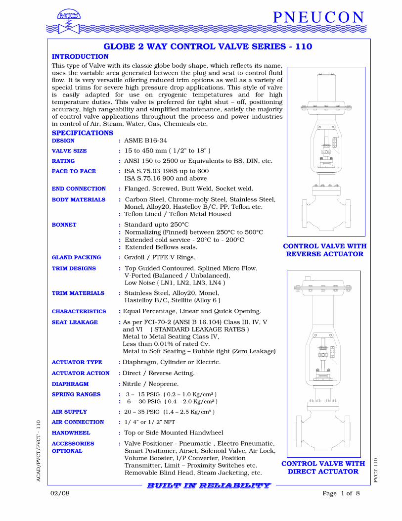
CONTROL VALVE WITH DIRECT ACTUATOR
BUILT IN RELIABILITY
02/08 Page 2 of 8
PN E U C O N
PV
CT-1
10
AC
AD
/PV
CT/PV
CT -
110
DESIGN FEATURES
>> High flow capacity and rangeability.
>> Large variety of Trim design.
>> Top opening for easy trim inspection without disturbing insulation or piping connection.
>> Tight closing for reliable control even when changes in pressure / temperature are sudden
and extreme.
>> Bolts located outside of the piping stress area to eliminate gasket crush problems,
reducing downtime.
>> Wide selection of actuators to meet most system requirement.
>> Rigorously proven on-site performance.
QUALITY AND PERFORMANCE GUARANTEE
>> Produced with Quality Systems accredited to ISO 9001 : 2000 ( Certificate No. 208920.)
by Bureau Veritas and “CE” in accordance to Pressure Equipments Directive and Regulations by Lloyd’s Register.
>> Full material certification available for all major component Parts.
>> Full guarantee on design and Performance.
>> All testing performed to the requirements of ANSI B16.34.
RANGEABILITY The Inherent rangeability of Pneucon standard trims is as given under.
STANDARD RANGEABILITY TRIM SIZE
CONTOURED LOW NOISE RANGE
ins mm
1/2 and 3/4 15 and 20 40 : 1 35 : 1
1 to 3 25 to 80 55 : 1 50 : 1
4 to 18 100 to 450 70 : 1 70 : 1
Microsplines Upto 400 : 1
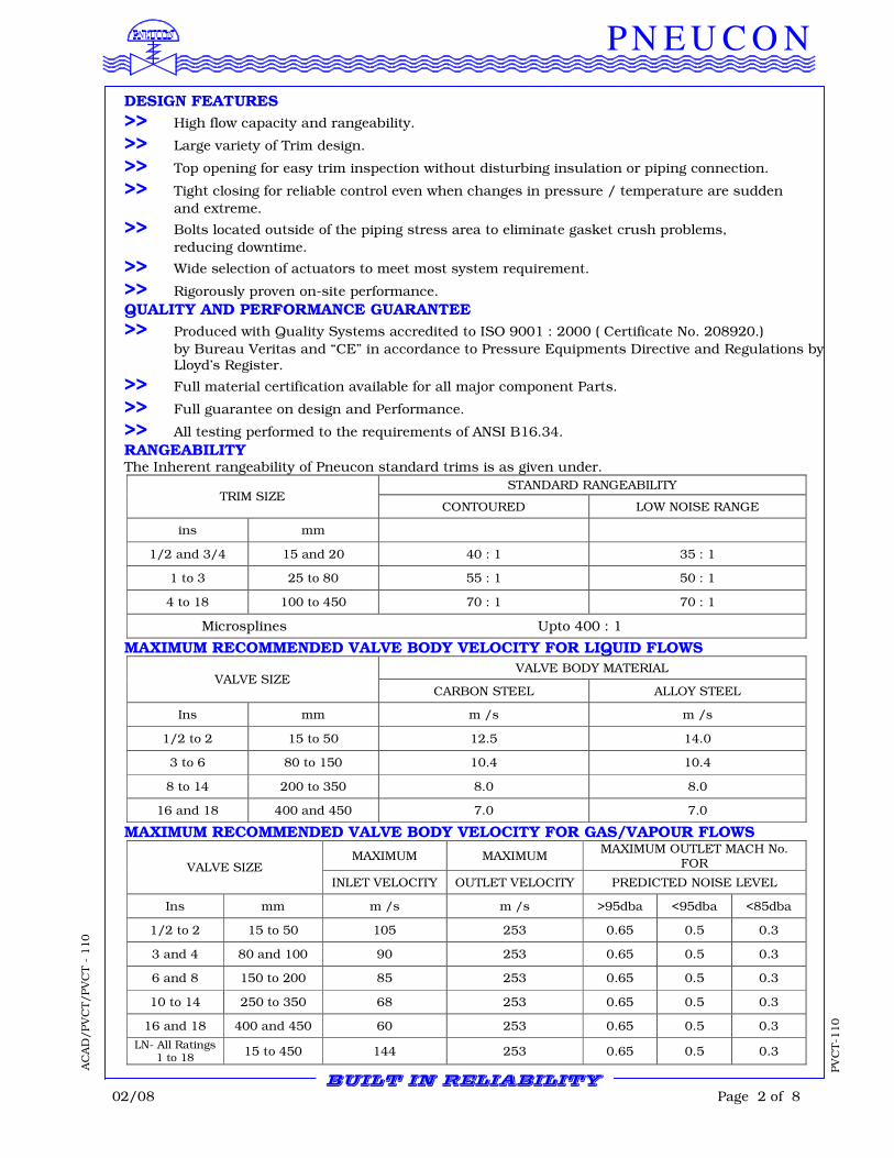
MAXIMUM RECOMMENDED VALVE BODY VELOCITY FOR LIQUID FLOWS
VALVE BODY MATERIAL VALVE SIZE
CARBON STEEL ALLOY STEEL
Ins mm m /s m /s
1/2 to 2 15 to 50 12.5 14.0
3 to 6 80 to 150 10.4 10.4
8 to 14 200 to 350 8.0 8.0
16 and 18 400 and 450 7.0 7.0
MAXIMUM RECOMMENDED VALVE BODY VELOCITY FOR GAS/VAPOUR FLOWS
MAXIMUM MAXIMUM MAXIMUM OUTLET MACH No.
FOR VALVE SIZE
INLET VELOCITY OUTLET VELOCITY PREDICTED NOISE LEVEL
Ins mm m /s m /s >95dba <95dba <85dba
1/2 to 2 15 to 50 105 253 0.65 0.5 0.3
3 and 4 80 and 100 90 253 0.65 0.5 0.3
6 and 8 150 to 200 85 253 0.65 0.5 0.3
10 to 14 250 to 350 68 253 0.65 0.5 0.3
16 and 18 400 and 450 60 253 0.65 0.5 0.3
LN- All Ratings 1 to 18
15 to 450 144 253 0.65 0.5 0.3
BUILT IN RELIABILITY
02/08 Page 3 of 8
PN E U C O N
PV
CT-1
10
PV
CT-1
10
AC
AD
/PV
CT/PV
CT -
110
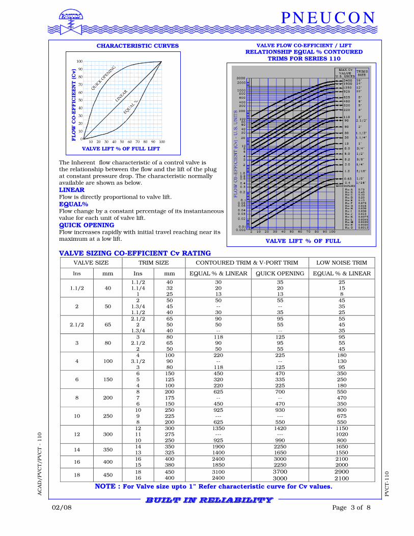
The Inherent flow characteristic of a control valve is the relationship between the flow and the lift of the plug at constant pressure drop. The characteristic normally available are shown as below.
LINEAR Flow is directly proportional to valve lift.
EQUAL% Flow change by a constant percentage of its instantaneous value for each unit of valve lift.
QUICK OPENING Flow increases rapidly with initial travel reaching near its maximum at a low lift.
VALVE SIZING CO-EFFICIENT Cv RATING
VALVE SIZE TRIM SIZE CONTOURED TRIM & V-PORT TRIM LOW NOISE TRIM
Ins mm Ins mm EQUAL % & LINEAR QUICK OPENING EQUAL % & LINEAR
1.1/2 40 1.1/2 1.1/4
1
40 32 25
30 20 13
35 20 13
25 15 8
2 50 2
1.3/4 1.1/2
50 45 40
50 -- 30
55 -- 35
45 35 25
2.1/2 65 2.1/2
2 1.3/4
65 50 40
90 50 --
95 55 --
55 45 35
3 80 3
2.1/2 2
80 65 50
118 90 50
125 95 55
95 55 45
4 100 4
3.1/2 3
100 90 80
220 --
118
225 --
125
180 130 95
6 150 6 5 4
150 125 100
450 320 220
470 335 225
350 250 180
8 200 8 7 6
200 175 150
625 --
450
700 --
470
550 470 350
10 250 10 9 8
250 225 200
925 --- 625
930 --- 550
800 675 550
12 300 12 11 10
300 275 250
1350 --- 925
1420 --- 990
1150 1020 800
14 350 14 13
350 325
1900 1400
2250 1650
1650 1550
16 400 16 15
400 380
2400 1850
3000 2250
2100 2000
18 450 18 16
450 400
3100 2400
3700 3000
2900 2100
NOTE : For Valve size upto 1” Refer characteristic curve for Cv values.
BUILT IN RELIABILITY
VALVE LIFT % OF FULL LIFT
VALVE FLOW CO-EFFICIENT / LIFT
RELATIONSHIP EQUAL % CONTOURED TRIMS FOR SERIES 110
CHARACTERISTIC CURVES
0
10
20
30
40
50
60
70
80
90
100
10 20 30 40 50 60 70 80 90 100
QU
ICK
OPEN
ING
LINEA
R
EQU
AL %
VALVE LIFT % OF FULL LIFT
FLO
W C
O-E
FF
ICIE
EN
T (C
v)
02/08 Page 4 of 8
PN E U C O N
PV
CT-1
10
AC
AD
/PV
CT/PV
CT -
110
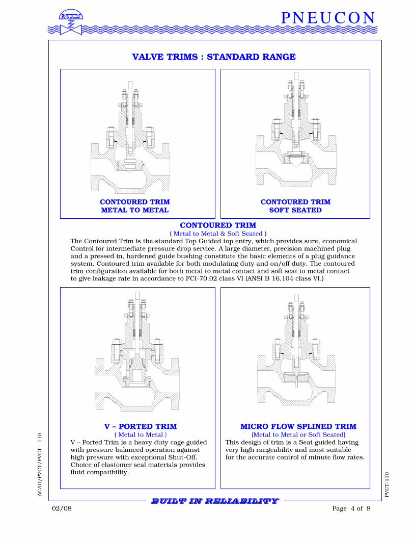
VALVE TRIMS : STANDARD RANGE
MICRO FLOW SPLINED TRIM (Metal to Metal or Soft Seated}
This design of trim is a Seat guided having very high rangeability and most suitable for the accurate control of minute flow rates.
CONTOURED TRIM
( Metal to Metal & Soft Seated ) The Contoured Trim is the standard Top Guided top entry, which provides sure, economical Control for intermediate pressure drop service. A large diameter, precision machined plug and a pressed in, hardened guide bushing constitute the basic elements of a plug guidance system. Contoured trim available for both modulating duty and on/off duty. The contoured trim configuration available for both metal to metal contact and soft seat to metal contact to give leakage rate in accordance to FCI-70.02 class VI (ANSI B 16.104 class VI.)
V – PORTED TRIM ( Metal to Metal }
V – Ported Trim is a heavy duty cage guided with pressure balanced operation against high pressure with exceptional Shut-Off. Choice of elastomer seal materials provides fluid compatibility.
BUILT IN RELIABILITY
CONTOURED TRIM METAL TO METAL
CONTOURED TRIM SOFT SEATED
02/08 Page 5 of 8
PN E U C O N
PV
CT-1
10
AC
AD
/PV
CT/PV
CT -
110
BUILT IN RELIABILITYBUILT IN RELIABILITYBUILT IN RELIABILITYBUILT IN RELIABILITY
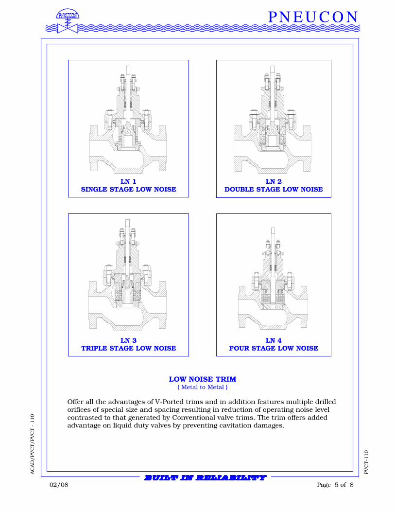
LOW NOISE TRIM ( Metal to Metal )
Offer all the advantages of V-Ported trims and in addition features multiple drilled orifices of special size and spacing resulting in reduction of operating noise level contrasted to that generated by Conventional valve trims. The trim offers added advantage on liquid duty valves by preventing cavitation damages.
LN 1 SINGLE STAGE LOW NOISE
LN 2 DOUBLE STAGE LOW NOISE
LN 3 TRIPLE STAGE LOW NOISE
LN 4 FOUR STAGE LOW NOISE
02/08 Page 6 of 8
PN E U C O N
PV
CT-1
10
AC
AD
/PV
CT/PV
CT -
110
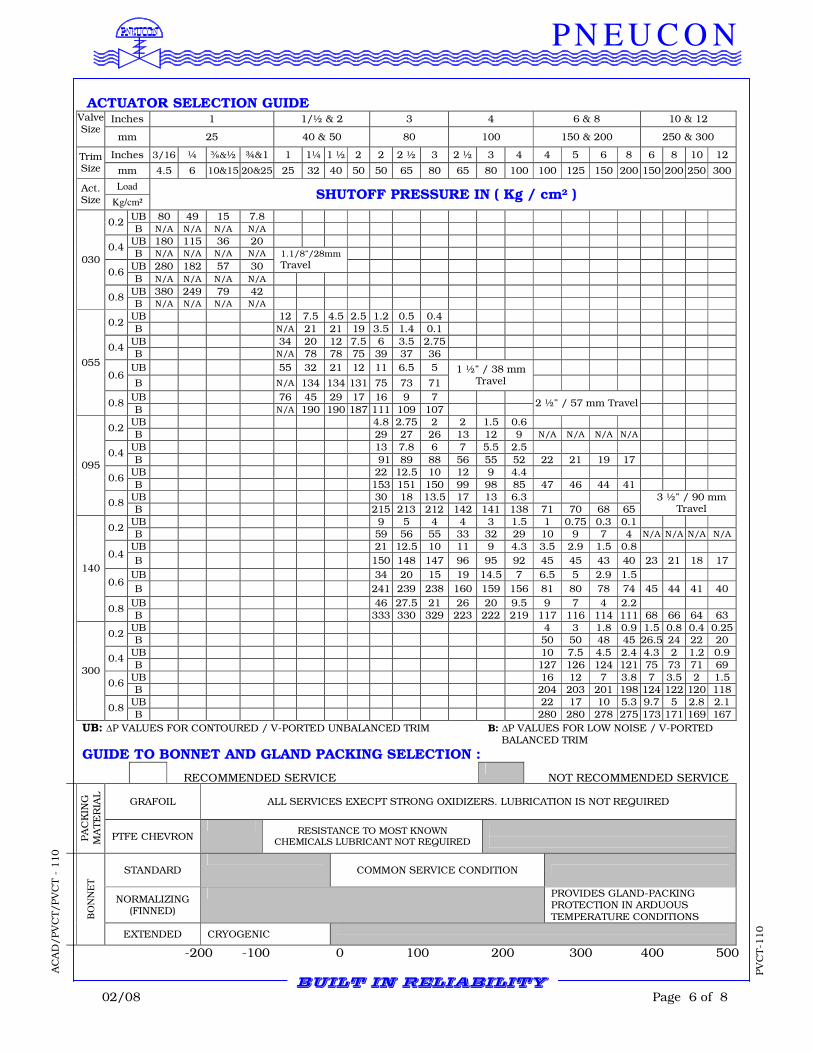
ACTUATOR SELECTION GUIDE
Inches 1 1/½ & 2 3 4 6 & 8 10 & 12 Valve Size
mm 25 40 & 50 80 100 150 & 200 250 & 300
Inches 3/16 ¼ ⅜&½ ¾&1 1 1¼ 1 ½ 2 2 2 ½ 3 2 ½ 3 4 4 5 6 8 6 8 10 12 Trim Size mm 4.5 6 10&15 20&25 25 32 40 50 50 65 80 65 80 100 100 125 150 200 150 200 250 300
Load Act. Size Kg/cm²
SHUTOFF PRESSURE IN ( Kg / cm² )
UB 80 49 15 7.8 0.2
B N/A N/A N/A N/A UB 180 115 36 20
0.4 B N/A N/A N/A N/A
UB 280 182 57 30
1.1/8”/28mm Travel
0.6 B N/A N/A N/A N/A
UB 380 249 79 42
030
0.8 B N/A N/A N/A N/A
UB 12 7.5 4.5 2.5 1.2 0.5 0.4 0.2
B N/A 21 21 19 3.5 1.4 0.1
UB 34 20 12 7.5 6 3.5 2.75 0.4
B N/A 78 78 75 39 37 36
UB 55 32 21 12 11 6.5 5 0.6
B N/A 134 134 131 75 73 71
1 ½” / 38 mm Travel
UB 76 45 29 17 16 9 7
055
0.8 B N/A 190 190 187 111 109 107
2 ½” / 57 mm Travel
UB 4.8 2.75 2 2 1.5 0.6 0.2
B 29 27 26 13 12 9 N/A N/A N/A N/A
UB 13 7.8 6 7 5.5 2.5 0.4
B 91 89 88 56 55 52 22 21 19 17 UB 22 12.5 10 12 9 4.4
0.6 B 153 151 150 99 98 85 47 46 44 41
UB 30 18 13.5 17 13 6.3
095
0.8 B 215 213 212 142 141 138 71 70 68 65
3 ½” / 90 mm Travel
UB 9 5 4 4 3 1.5 1 0.75 0.3 0.1 0.2
B 59 56 55 33 32 29 10 9 7 4 N/A N/A N/A N/A
UB 21 12.5 10 11 9 4.3 3.5 2.9 1.5 0.8 0.4
B 150 148 147 96 95 92 45 45 43 40 23 21 18 17
UB 34 20 15 19 14.5 7 6.5 5 2.9 1.5 0.6
B 241 239 238 160 159 156 81 80 78 74 45 44 41 40
UB 46 27.5 21 26 20 9.5 9 7 4 2.2
140
0.8 B 333 330 329 223 222 219 117 116 114 111 68 66 64 63
UB 4 3 1.8 0.9 1.5 0.8 0.4 0.25 0.2
B 50 50 48 45 26.5 24 22 20
UB 10 7.5 4.5 2.4 4.3 2 1.2 0.9 0.4
B 127 126 124 121 75 73 71 69
UB 16 12 7 3.8 7 3.5 2 1.5 0.6
B 204 203 201 198 124 122 120 118 UB 22 17 10 5.3 9.7 5 2.8 2.1
300
0.8 B 280 280 278 275 173 171 169 167
UB: ∆P VALUES FOR CONTOURED / V-PORTED UNBALANCED TRIM B: ∆P VALUES FOR LOW NOISE / V-PORTED BALANCED TRIM
GUIDE TO BONNET AND GLAND PACKING SELECTION :
GRAFOIL ALL SERVICES EXECPT STRONG OXIDIZERS. LUBRICATION IS NOT REQUIRED
PA
CK
ING
M
ATE
RIA
L
PTFE CHEVRON
RESISTANCE TO MOST KNOWN CHEMICALS LUBRICANT NOT REQUIRED
STANDARD
COMMON SERVICE CONDITION
NORMALIZING (FINNED)
PROVIDES GLAND-PACKING PROTECTION IN ARDUOUS TEMPERATURE CONDITIONS B
ON
NE
T
EXTENDED CRYOGENIC
-200 -100 0 100 200 300 400 500
RECOMMENDED SERVICE NOT RECOMMENDED SERVICE
BUILT IN RELIABILITY
02/08 Page 7 of 8
PN E U C O N
PV
CT-1
10
AC
AD
/PV
CT/PV
CT -
110
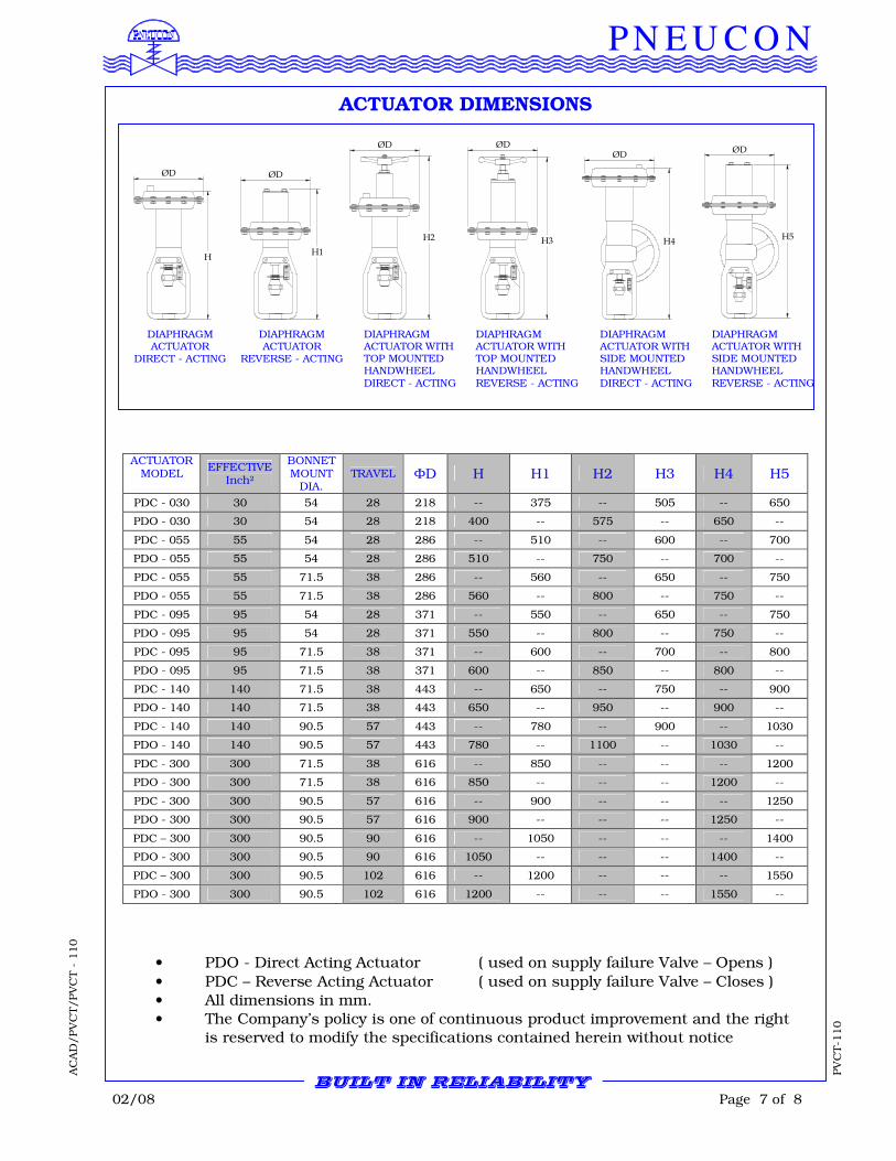
ACTUATOR DIMENSIONS
ACTUATOR MODEL
EFFECTIVE Inch2
BONNET MOUNT
DIA. TRAVEL ФD H H1 H2 H3 H4 H5
PDC - 030 30 54 28 218 -- 375 -- 505 -- 650
PDO - 030 30 54 28 218 400 -- 575 -- 650 --
PDC - 055 55 54 28 286 -- 510 -- 600 -- 700
PDO - 055 55 54 28 286 510 -- 750 -- 700 --
PDC - 055 55 71.5 38 286 -- 560 -- 650 -- 750
PDO - 055 55 71.5 38 286 560 -- 800 -- 750 --
PDC - 095 95 54 28 371 -- 550 -- 650 -- 750
PDO - 095 95 54 28 371 550 -- 800 -- 750 --
PDC - 095 95 71.5 38 371 -- 600 -- 700 -- 800
PDO - 095 95 71.5 38 371 600 -- 850 -- 800 --
PDC - 140 140 71.5 38 443 -- 650 -- 750 -- 900
PDO - 140 140 71.5 38 443 650 -- 950 -- 900 --
PDC - 140 140 90.5 57 443 -- 780 -- 900 -- 1030
PDO - 140 140 90.5 57 443 780 -- 1100 -- 1030 --
PDC - 300 300 71.5 38 616 -- 850 -- -- -- 1200
PDO - 300 300 71.5 38 616 850 -- -- -- 1200 --
PDC - 300 300 90.5 57 616 -- 900 -- -- -- 1250
PDO - 300 300 90.5 57 616 900 -- -- -- 1250 --
PDC – 300 300 90.5 90 616 -- 1050 -- -- -- 1400
PDO - 300 300 90.5 90 616 1050 -- -- -- 1400 --
PDC – 300 300 90.5 102 616 -- 1200 -- -- -- 1550
PDO - 300 300 90.5 102 616 1200 -- -- -- 1550 --
• PDO - Direct Acting Actuator ( used on supply failure Valve – Opens )
• PDC – Reverse Acting Actuator ( used on supply failure Valve – Closes ) • All dimensions in mm. • The Company’s policy is one of continuous product improvement and the right
is reserved to modify the specifications contained herein without notice
BUILT IN RELIABILITY
ØD
H3H2
ØD
ØD
H1H
ØD
H5
ØD
H4
ØD
DIAPHRAGM ACTUATOR
DIRECT - ACTING
DIAPHRAGM ACTUATOR
REVERSE - ACTING
DIAPHRAGM ACTUATOR WITH TOP MOUNTED HANDWHEEL DIRECT - ACTING
DIAPHRAGM ACTUATOR WITH TOP MOUNTED HANDWHEEL REVERSE - ACTING
DIAPHRAGM ACTUATOR WITH SIDE MOUNTED HANDWHEEL DIRECT - ACTING
DIAPHRAGM ACTUATOR WITH SIDE MOUNTED HANDWHEEL REVERSE - ACTING
02/08 Page 8 of 8
PN E U C O N
PV
CT-1
10 D
esig
ned B
y :
R
ajes
h
AC
AD
/PV
CT/PV
CT -
110
The Company’s policy is one of continuous product improvement and the right is reserved to modify the specifications contained herein without noti
P N E U C O N V A L V E S P V T. L T D.
Plot No: A-35, Road No. 10,Wagle Industrial Estate, Thane – 400 604, India.
Phone: +9122 2583 8371, 2583 8372, Fax : +9122 2583 8373 E-Mail: [email protected] Web: www. pneuconvalves.com
IN TECHANICAL COLLABORATION WITH VALVE SOLUTIONS LTD. – U .K
BUILT IN RELIABILITY
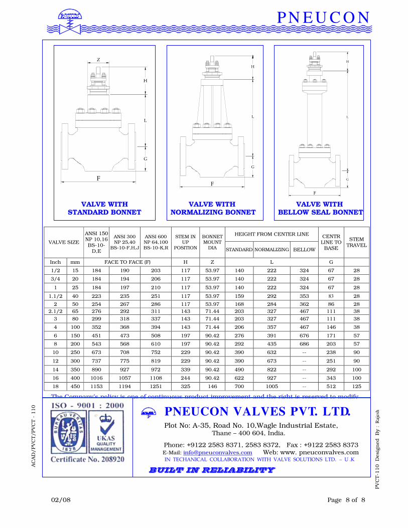
HEIGHT FROM CENTER LINE
VALVE SIZE
ANSI 150 NP 10,16 BS-10-
D,E
ANSI 300 NP 25,40
BS-10-F,H,J
ANSI 600 NP 64,100 BS-10-K,R
STEM IN UP
POSITION
BONNET MOUNT
DIA STANDARD NORMALIZING BELLOW
CENTR LINE TO
BASE
STEM TRAVEL
Inch mm FACE TO FACE (F) H Z L G
1/2 15 184 190 203 117 53.97 140 222 324 67 28
3/4 20 184 194 206 117 53.97 140 222 324 67 28
1 25 184 197 210 117 53.97 140 222 324 67 28
1.1/2 40 223 235 251 117 53.97 159 292 353 83 28
2 50 254 267 286 117 53.97 168 284 362 86 28
2.1/2 65 276 292 311 143 71.44 203 327 467 111 38
3 80 299 318 337 143 71.44 203 327 467 111 38
4 100 352 368 394 143 71.44 206 357 467 146 38
6 150 451 473 508 197 90.42 276 391 676 171 57
8 200 543 568 610 197 90.42 292 435 686 203 57
10 250 673 708 752 229 90.42 390 632 -- 238 90
12 300 737 775 819 229 90.42 390 673 -- 251 90
14 350 890 927 972 339 90.42 490 822 -- 292 100
16 400 1016 1057 1108 244 90.42 622 927 -- 343 100
18 450 1153 1194 1251 325 146 700 1005 -- 512 125
F
G
L
H
Z
F
G
L
H
VALVE WITH
STANDARD BONNET VALVE WITH
BELLOW SEAL BONNET
H
L
G
F
VALVE WITH NORMALIZING BONNET