Embed Size (px)
Citation preview
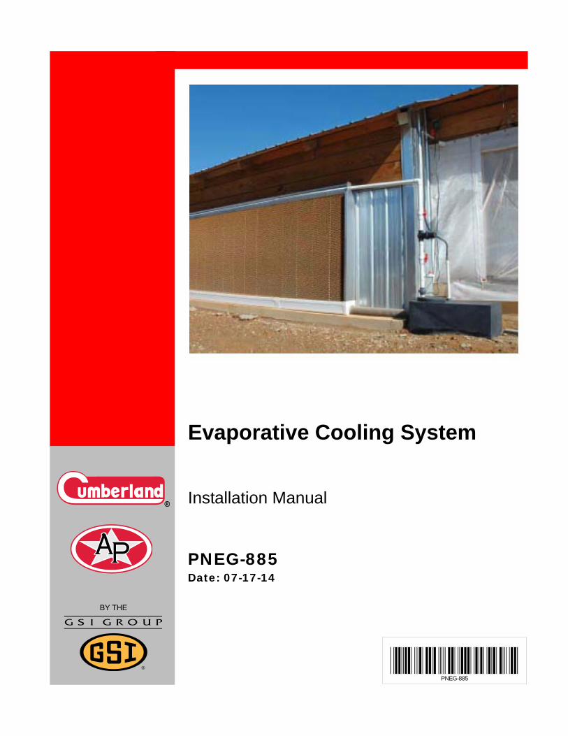
PNEG-885
Evaporative Cooling System
Installation Manual
PNEG-885Date: 07-17-14

2 PNEG-885 Evaporative Cooling System
NOTE: To achieve maximum efficiency and performance while ensuring long life from your Re-circulating Cooling System, it is imperative that it be installed and maintained correctly. Please read all instructions carefully before beginning installation.
Table of Contents
PNEG-885 Evaporative Cooling System 3
ContentsChapter 1 Safety .....................................................................................................................................................4
Safety Guidelines ...................................................................................................................................4Safety Instructions ..................................................................................................................................5
Chapter 2 Introduction to Evaporative Cooling ..................................................................................................6Dry Bulb Temperature ............................................................................................................................6Wet Bulb Temperature ...........................................................................................................................6Wet Bulb Depression .............................................................................................................................6Evaporative Pad Cooling Efficiency .......................................................................................................6Enthalpy .................................................................................................................................................6Specific Volume .....................................................................................................................................6Dew Point Temperature .........................................................................................................................6Relative Humidity ...................................................................................................................................6
Chapter 3 Evaporative Cooling Theory and Benefits .........................................................................................7Evaporative Cooling Theory ...................................................................................................................7Benefits ..................................................................................................................................................7Placing the Evaporative Cooling System ...............................................................................................7
Chapter 4 Evaporative System Installation .........................................................................................................8RCS Evaporative Cooling Rough Opening ............................................................................................8Closed Top Cover Assembly Installation .............................................................................................11Open Top Cover Assembly Installation ................................................................................................14Trough Assembly Installation ...............................................................................................................16Jet Pump System .................................................................................................................................18Installing the Supply Line and Spray Bar .............................................................................................21End Panel Assembly Installation ..........................................................................................................22Setting the Media Pad ..........................................................................................................................23Installing the Reservoir Tank ................................................................................................................26Installing the Vertical Piping Assembly ................................................................................................27End Jet Pump System ..........................................................................................................................29Center Jet Pump System .....................................................................................................................32Installing the Float Valve Assembly .....................................................................................................35Wiring the Re-Circulating Cooling System ...........................................................................................35
Chapter 5 Operation and Maintenance of the Re-Circulating Cooling System ..............................................36Initial Start-Up New Media ...................................................................................................................36Normal Operation .................................................................................................................................36Annual Shut Down and Start-Up Process ............................................................................................37Annual Start-Up ....................................................................................................................................37Algae/Bacteria Control .........................................................................................................................37Maintenance/Water Chemistry .............................................................................................................38Re-Circulating Closed Top Cooling System (RCS-10)......................................................................... 39Re-Circulating Stainless Steel Open Top (RCS-10-OT) ...................................................................... 40Re-Circulating Aluminum Open Top (RCS-10-OTA) ............................................................................41
Chapter 6 Appendix-I: Pad Retainers .................................................................................................................42Installation of Pad Retainers ................................................................................................................42
Chapter 7 Appendix-II: Offset Support Brackets ..............................................................................................43RCS Evaporative Cooling Rough Opening ..........................................................................................43
Chapter 8 Warranty ..............................................................................................................................................45
4 PNEG-885 Evaporative Cooling System
1. Safety
Safety Guidelines
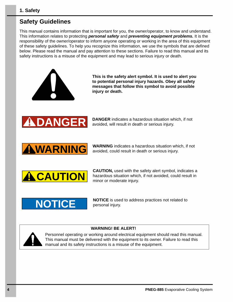
This manual contains information that is important for you, the owner/operator, to know and understand. This information relates to protecting personal safety and preventing equipment problems. It is the responsibility of the owner/operator to inform anyone operating or working in the area of this equipment of these safety guidelines. To help you recognize this information, we use the symbols that are defined below. Please read the manual and pay attention to these sections. Failure to read this manual and its safety instructions is a misuse of the equipment and may lead to serious injury or death.
DANGER
WARNING
CAUTION
NOTICE
This is the safety alert symbol. It is used to alert you to potential personal injury hazards. Obey all safety messages that follow this symbol to avoid possible injury or death.
WARNING indicates a hazardous situation which, if not avoided, could result in death or serious injury.
CAUTION, used with the safety alert symbol, indicates a hazardous situation which, if not avoided, could result in minor or moderate injury.
NOTICE is used to address practices not related to personal injury.
DANGER indicates a hazardous situation which, if not avoided, will result in death or serious injury.
Personnel operating or working around electrical equipment should read this manual. This manual must be delivered with the equipment to its owner. Failure to read this manual and its safety instructions is a misuse of the equipment.
WARNING! BE ALERT!
1. Safety
PNEG-885 Evaporative Cooling System 5
Safety Instructions
Our foremost concern is your safety and the safety of others associated with this equipment. We want to keep you as a customer. This manual is to help you understand safe operating procedures and some problems that may be encountered by the operator and other personnel.
As owner and/or operator, it is your responsibility to know what requirements, hazards, and precautions exist, and to inform all personnel associated with the equipment or in the area. Safety precautions may be required from the personnel. Avoid any alterations to the equipment. Such alterations may produce a very dangerous situation where SERIOUS INJURY or DEATH may occur.
This equipment shall be installed in accordance with the current installation codes and applicable regulations, which should be carefully followed in all cases. Authorities having jurisdiction should be consulted before installations are made.
GSI Group, recommends that you contact your local power company and have a representative review your installation so your wiring will be compatible with their system and so that you will have adequate power supplied to your unit.
6 PNEG-885 Evaporative Cooling System
2. Introduction to Evaporative Cooling
When non-saturated air comes in contact with free moisture and the two are thermally isolated from an outside heat source, there is a transfer of mass and heat. Because the vapor pressure of the free water surface is higher than that of the unsaturated air, water transfers in response to the differential. The transfer involves a change of state from liquid to vapor, requiring heat of vaporization. The heat recovery for this change of state comes from the sensible heat content of both the air and water, resulting in a drop of temperature of both. As the temperature in the immediate vicinity of the interface drops and creates a temperature differential within the air vapor mixture, a transfer of heat occurs as the whole system changes to a thermodynamic balance. Since no outside heat is added during the process, total heat content does not change. There is simply an adiabatic exchange of latent heat for sensible heat. A change in environment results, however, from the change of the state of water and change in temperature of the air vapor mixture.
Dry Bulb Temperature
Dry bulb temperature is measured by a mercury in glass thermometer properly shielded from radiation, wiped dry and given sufficient time to reach a steady state reading.
Wet Bulb Temperature
Wet bulb temperature is a value indicated on an ordinary mercury glass thermometer, whose bulb is covered by a wet wick and placed in a 1000 FPM moving stream of air.
Wet Bulb Depression
Wet bulb depression is the difference in degrees between dry bulb and wet bulb temperature.
Evaporative Pad Cooling Efficiency
Evaporative pad cooling efficiency is the percentage of wet bulb depression that the air is cooled as it passes through the pad.
Enthalpy
Enthalpy is the internal energy content of an air-water-vapor mixture. The energy contained in the mixture can be present both as sensible heat (indicated by dry bulb temperature) and latent heat of vaporization (energy content of the water vapor).
Specific Volume
Specific volume is the cubic feet of the mixture per pound of dry air.
Dew Point Temperature
Dew point temperature is the temperature at which moisture will start to condense from the air.
Relative Humidity
Relative humidity is the ratio of the partial pressure of the water vapor in moist air to the vapor pressure. The relationship for the relative humidity is expressed as a percent.
PNEG-885 Evaporative Cooling System 7
3. Evaporative Cooling Theory and Benefits
Evaporative Cooling Theory
Evaporative cooling works by evaporating water into the air. In order for water to evaporate, it must absorb heat, which is supplied by the outside air brought into the house for ventilation. As hot outside air comes in contact with the wet evaporative cooling pad, some of the heat is absorbed by water and the air becomes cooler. The water does not increase in temperature during this process, but only changes in state from a liquid to a vapor.
How well evaporative cooling works depends partly on the weather. The air temperature in the building can only be theoretically lowered to the dew point temperature. The dew point temperature can be measured when the air is completely saturated with water (when the relative humidity is 100 percent). Generally, the difference between the air temperature and the dew point temperature is greatest during the warmest hours of the day. Therefore, an evaporative cooling system is most effective during the hottest hours of the day.
The theoretical efficiency of the system is limited by the dew point temperature. The actual air temperature in the building cannot be cooled to dew point temperature. Using a properly maintained system, however, the air temperature in the building can be reduced to within 3°F - 5°F of the dew point temperature.
Benefits
Livestock and poultry cannot adequately remove excess body heat through sweating. The main way animals lose heat is by the atmosphere. However, when the air temperature approaches the body temperature of the animal, it becomes difficult to reduce body temperature through heat loss to the atmosphere. Therefore, external cooling must be provided.
Evaporative cooling is a very cost effective way of reducing heat stress incurred by warm summer temperatures. By providing a comfortably cooled environment, animals and poultry can experience better weight gain, better production and improved reproductive characteristics.
Placing the Evaporative Cooling System
Each building and system is a little different just as management styles differ. The system can be located such that it will be more of an outside attachment to the building or may be incorporated into the building structure so that it is considered inside. Some of this depends on whether it is preferred to service from inside or outside. It may depend on environmental conditions, especially in the winter where the system is subject to less harsh conditions if located between a curtain and the animals. A closed curtain will serve to prevent blowing dust, debris, rain and ice from entering the system.
8 PNEG-885 Evaporative Cooling System
4. Evaporative System Installation
RCS Evaporative Cooling Rough Opening
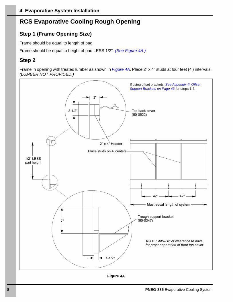
Step 1 (Frame Opening Size)
Frame should be equal to length of pad.
Frame should be equal to height of pad LESS 1/2". (See Figure 4A.)
Step 2
Frame in opening with treated lumber as shown in Figure 4A. Place 2" x 4" studs at four feet (4') intervals. (LUMBER NOT PROVIDED.)
Figure 4A
If using offset brackets, See Appendix-II: Offset Support Brackets on Page 43 for steps 1-3.
4. Evaporative System Installation
PNEG-885 Evaporative Cooling System 9
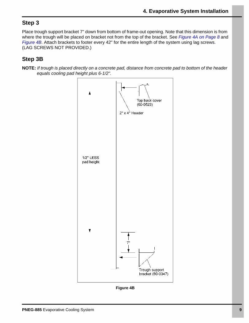
Step 3
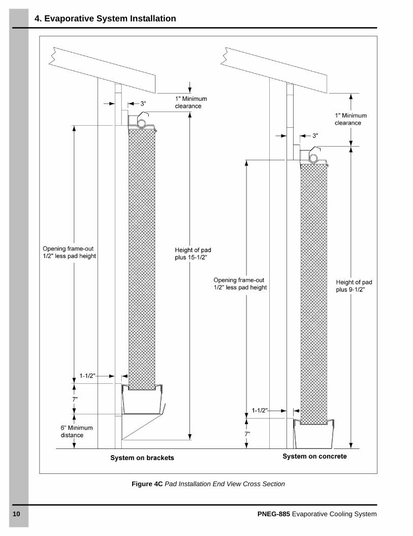
Place trough support bracket 7" down from bottom of frame-out opening. Note that this dimension is from where the trough will be placed on bracket not from the top of the bracket. See Figure 4A on Page 8 andFigure 4B. Attach brackets to footer every 42" for the entire length of the system using lag screws. (LAG SCREWS NOT PROVIDED.)
Step 3B
NOTE: If trough is placed directly on a concrete pad, distance from concrete pad to bottom of the header equals cooling pad height plus 6-1/2".
Figure 4B
4. Evaporative System Installation
10 PNEG-885 Evaporative Cooling System
Figure 4C Pad Installation End View Cross Section
4. Evaporative System Installation
PNEG-885 Evaporative Cooling System 11
Closed Top Cover Assembly Installation
Step 4
Check rough opening for specified distance from support brackets (1/2" less than pad height).
If using the open top system, proceed to Step 5A on Page 14.
Step 5
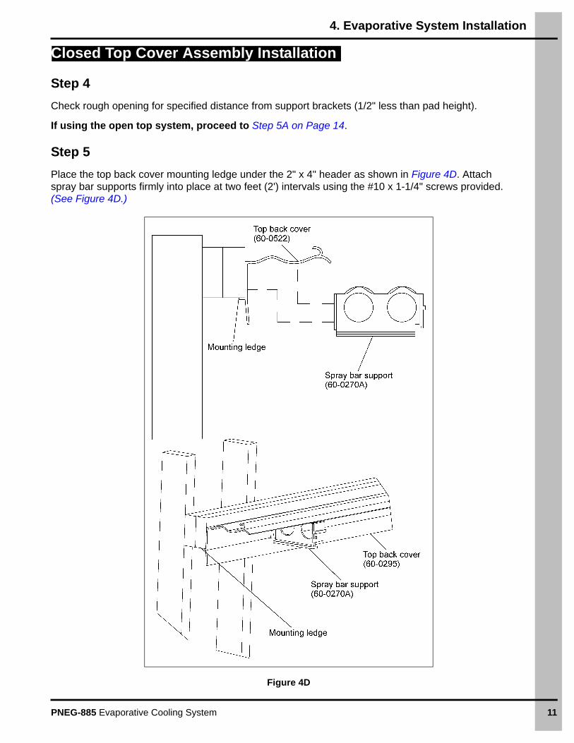
Place the top back cover mounting ledge under the 2" x 4" header as shown in Figure 4D. Attach spray bar supports firmly into place at two feet (2') intervals using the #10 x 1-1/4" screws provided. (See Figure 4D.)
Figure 4D
4. Evaporative System Installation
12 PNEG-885 Evaporative Cooling System
Closed Top Cover Assembly Installation (Continued)
Step 6
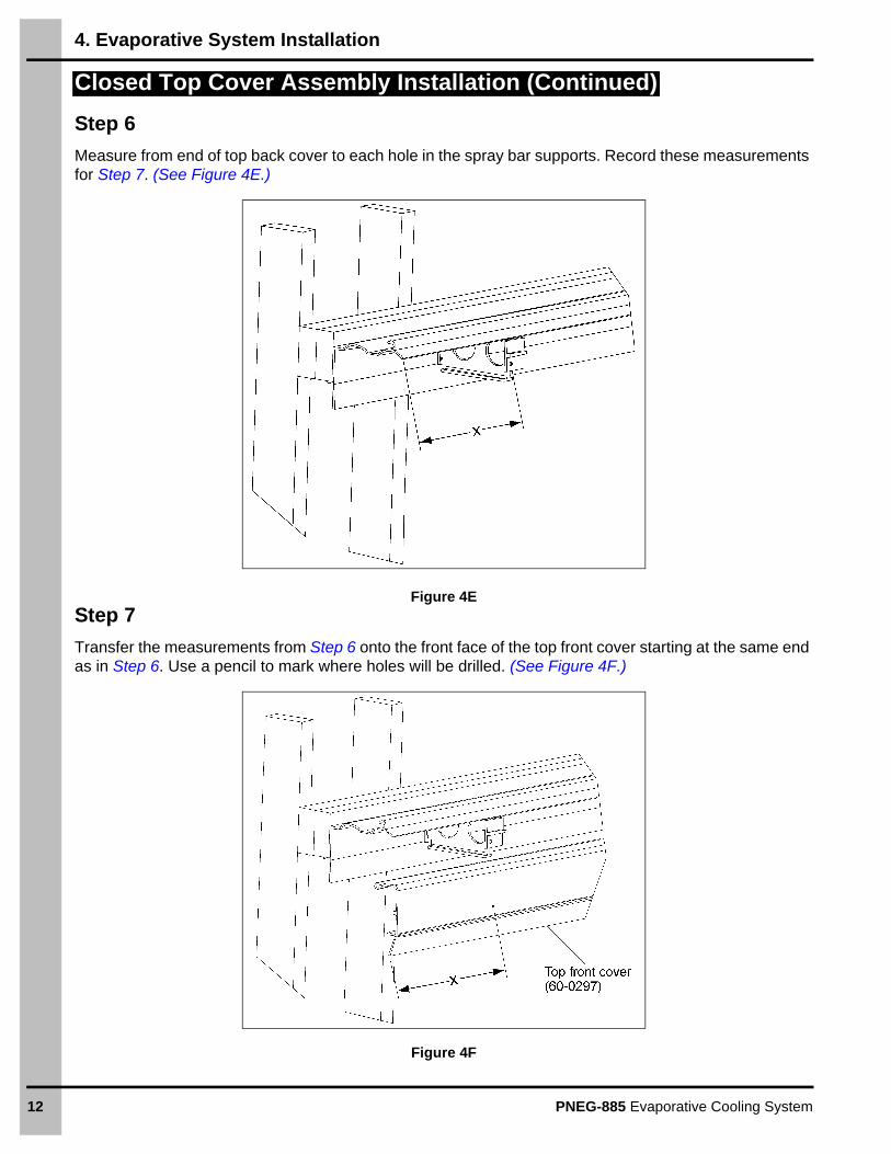
Measure from end of top back cover to each hole in the spray bar supports. Record these measurements for Step 7. (See Figure 4E.)
Figure 4E
Step 7
Transfer the measurements from Step 6 onto the front face of the top front cover starting at the same end as in Step 6. Use a pencil to mark where holes will be drilled. (See Figure 4F.)
Figure 4F
4. Evaporative System Installation
PNEG-885 Evaporative Cooling System 13
Closed Top Cover Assembly Installation (Continued)
Step 8
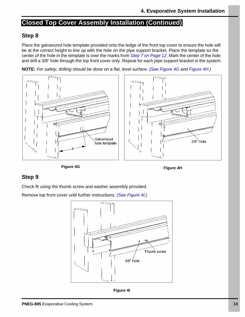
Place the galvanized hole template provided onto the ledge of the front top cover to ensure the hole will be at the correct height to line up with the hole on the pipe support bracket. Place the template so the center of the hole in the template is over the marks from Step 7 on Page 12. Mark the center of the hole and drill a 3/8" hole through the top front cover only. Repeat for each pipe support bracket in the system.
NOTE: For safety, drilling should be done on a flat, level surface. (See Figure 4G and Figure 4H.)
Figure 4G Figure 4H
Step 9
Check fit using the thumb screw and washer assembly provided.
Remove top front cover until further instructions. (See Figure 4I.)
Figure 4I
4. Evaporative System Installation
14 PNEG-885 Evaporative Cooling System
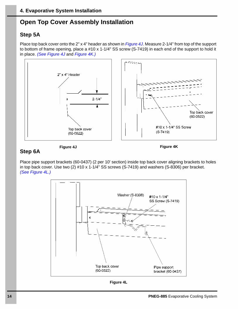
Open Top Cover Assembly Installation
Step 5A
Place top back cover onto the 2" x 4" header as shown in Figure 4J. Measure 2-1/4" from top of the support to bottom of frame opening, place a #10 x 1-1/4" SS screw (S-7419) in each end of the support to hold it in place. (See Figure 4J and Figure 4K.)
Figure 4J Figure 4K Step 6A
Place pipe support brackets (60-0437) (2 per 10' section) inside top back cover aligning brackets to holes in top back cover. Use two (2) #10 x 1-1/4" SS screws (S-7419) and washers (S-8306) per bracket. (See Figure 4L.)
Figure 4L
4. Evaporative System Installation
PNEG-885 Evaporative Cooling System 15
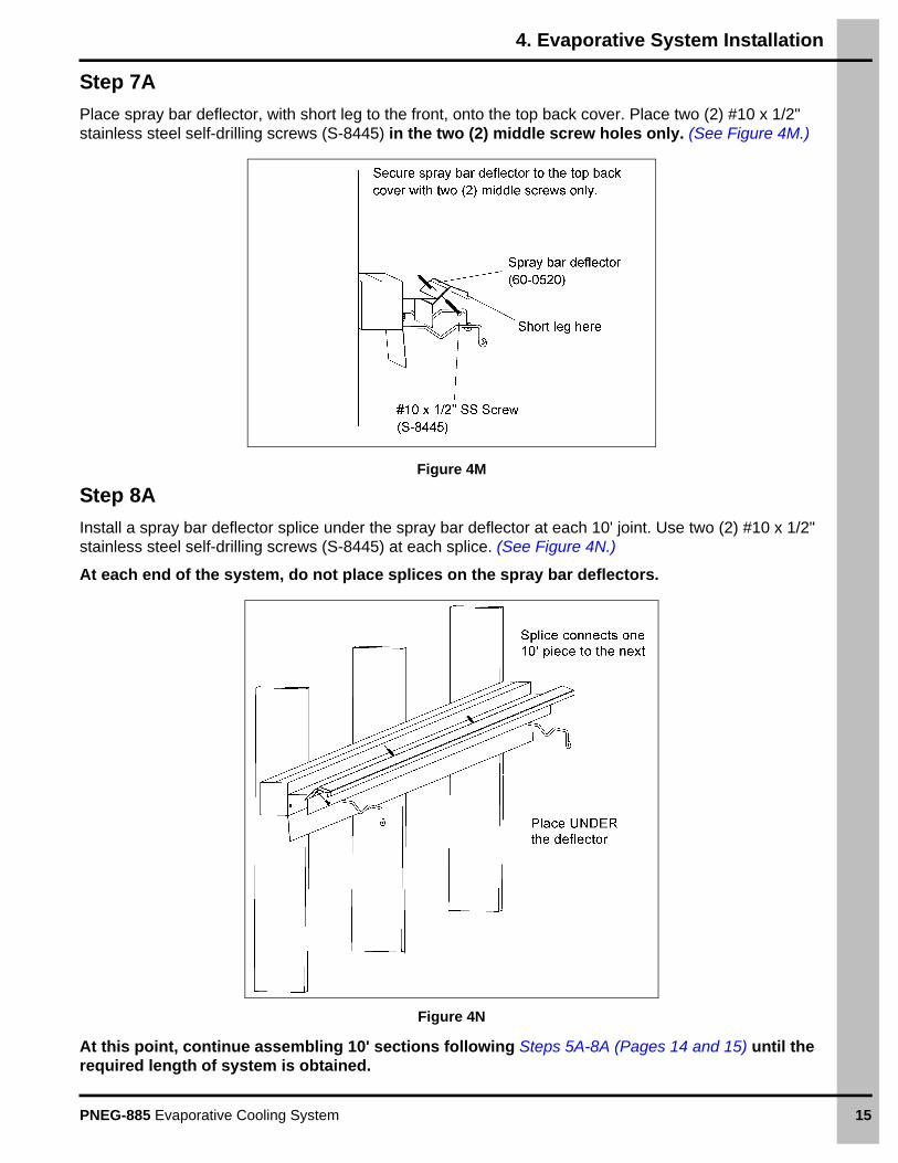
Step 7A
Place spray bar deflector, with short leg to the front, onto the top back cover. Place two (2) #10 x 1/2" stainless steel self-drilling screws (S-8445) in the two (2) middle screw holes only. (See Figure 4M.)
Figure 4M
Step 8A
Install a spray bar deflector splice under the spray bar deflector at each 10' joint. Use two (2) #10 x 1/2" stainless steel self-drilling screws (S-8445) at each splice. (See Figure 4N.)
At each end of the system, do not place splices on the spray bar deflectors.
Figure 4N
At this point, continue assembling 10' sections following Steps 5A-8A (Pages 14 and 15) until the required length of system is obtained.
4. Evaporative System Installation
16 PNEG-885 Evaporative Cooling System
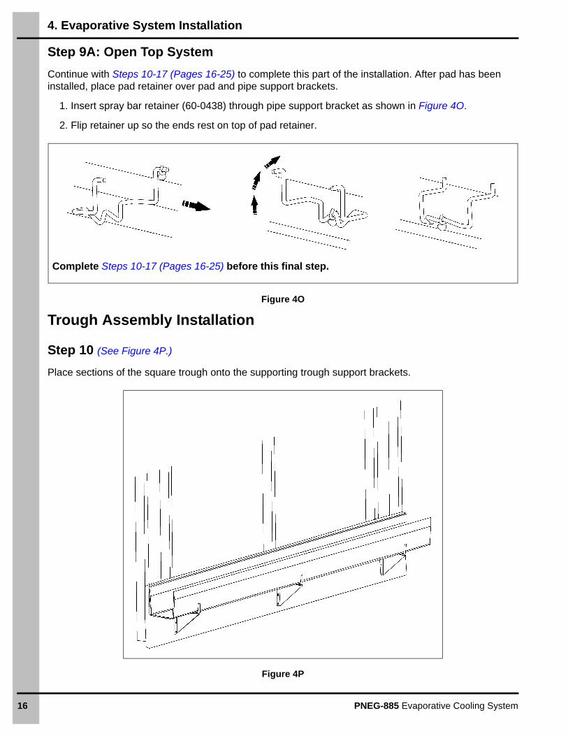
Step 9A: Open Top System
Continue with Steps 10-17 (Pages 16-25) to complete this part of the installation. After pad has been installed, place pad retainer over pad and pipe support brackets.
1. Insert spray bar retainer (60-0438) through pipe support bracket as shown in Figure 4O.
2. Flip retainer up so the ends rest on top of pad retainer.
Figure 4O
Trough Assembly Installation
Step 10 (See Figure 4P.)
Place sections of the square trough onto the supporting trough support brackets.
Figure 4P
Complete Steps 10-17 (Pages 16-25) before this final step.
4. Evaporative System Installation
PNEG-885 Evaporative Cooling System 17
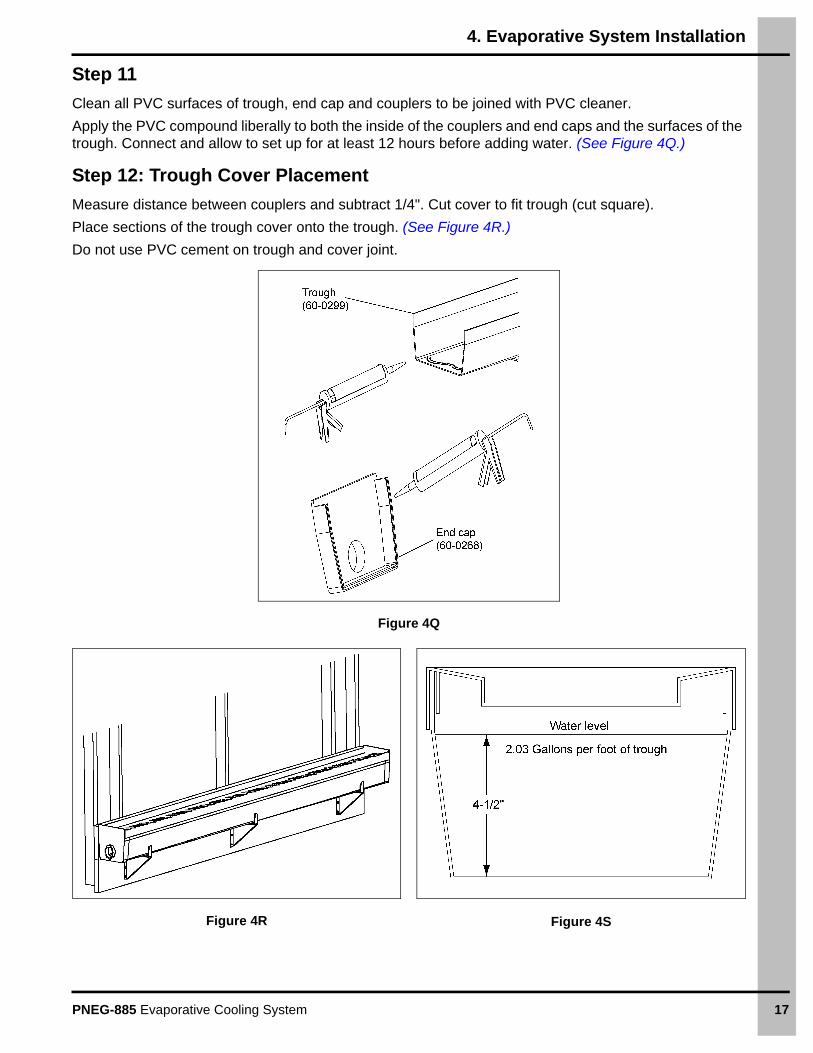
Step 11
Clean all PVC surfaces of trough, end cap and couplers to be joined with PVC cleaner.
Apply the PVC compound liberally to both the inside of the couplers and end caps and the surfaces of the trough. Connect and allow to set up for at least 12 hours before adding water. (See Figure 4Q.)
Step 12: Trough Cover Placement
Measure distance between couplers and subtract 1/4". Cut cover to fit trough (cut square).
Place sections of the trough cover onto the trough. (See Figure 4R.)
Do not use PVC cement on trough and cover joint.
Figure 4Q
Figure 4R Figure 4S
4. Evaporative System Installation
18 PNEG-885 Evaporative Cooling System
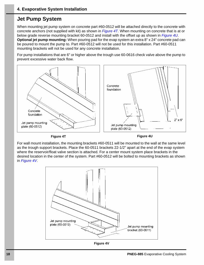
Jet Pump SystemWhen mounting jet pump system on concrete part #60-0512 will be attached directly to the concrete with concrete anchors (not supplied with kit) as shown in Figure 4T. When mounting on concrete that is at or below grade reverse mounting bracket 60-0512 and install with the offset up as shown in Figure 4U. Optional jet pump mounting: When pouring pad for the evap system an extra 8" x 24" concrete pad can be poured to mount the pump to. Part #60-0512 will not be used for this installation. Part #60-0511 mounting brackets will not be used for any concrete installation.
For pump installations that are 6" or higher above the trough use 60-0616 check valve above the pump to prevent excessive water back flow.
Figure 4T Figure 4U
For wall mount installation, the mounting brackets #60-0511 will be mounted to the wall at the same level as the trough support brackets. Place the 60-0511 brackets 22-1/2" apart at the end of the evap system where the reservoir/float valve section is attached. For a center mount system place brackets in the desired location in the center of the system. Part #60-0512 will be bolted to mounting brackets as shown in Figure 4V.
Figure 4V
4. Evaporative System Installation
PNEG-885 Evaporative Cooling System 19
Jet Pump System (Continued)
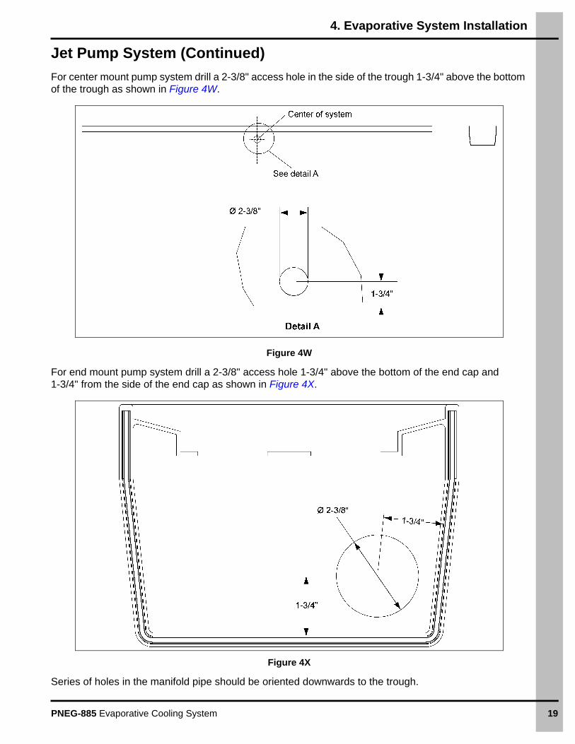
For center mount pump system drill a 2-3/8" access hole in the side of the trough 1-3/4" above the bottom of the trough as shown in Figure 4W.
Figure 4W
For end mount pump system drill a 2-3/8" access hole 1-3/4" above the bottom of the end cap and 1-3/4" from the side of the end cap as shown in Figure 4X.
Figure 4X
Series of holes in the manifold pipe should be oriented downwards to the trough.
4. Evaporative System Installation
20 PNEG-885 Evaporative Cooling System
Jet Pump System (Continued)
Figure 4Y
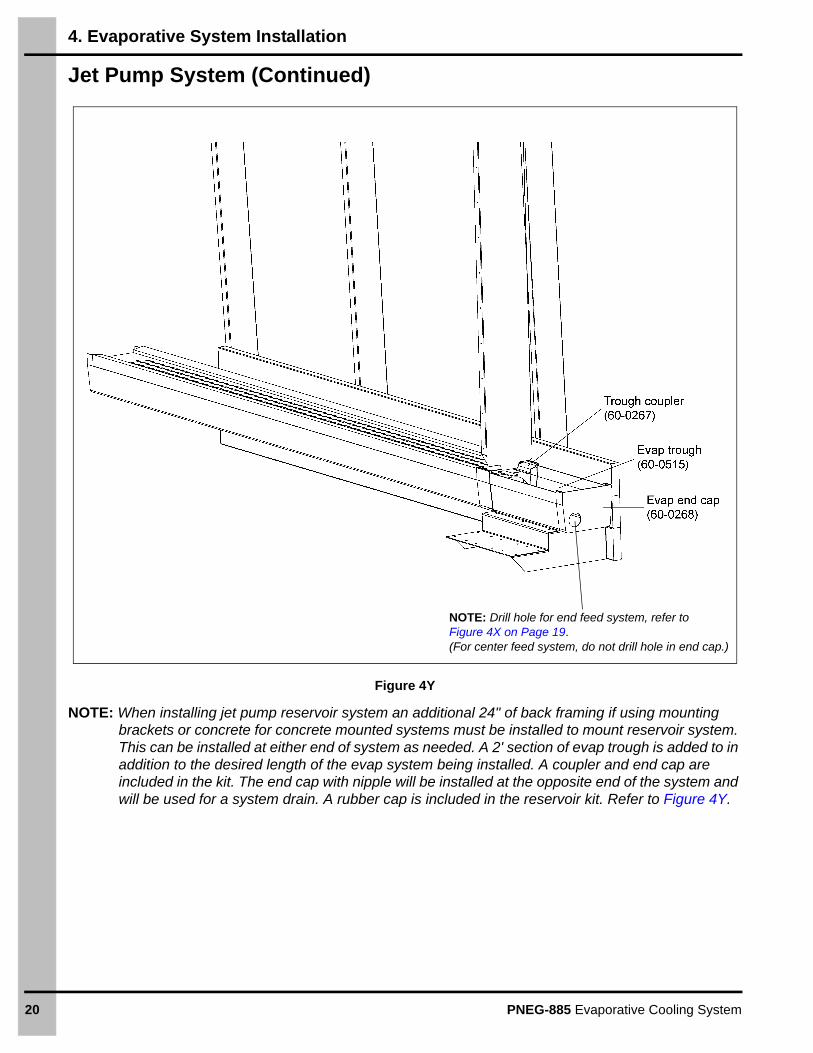
NOTE: When installing jet pump reservoir system an additional 24" of back framing if using mounting brackets or concrete for concrete mounted systems must be installed to mount reservoir system. This can be installed at either end of system as needed. A 2' section of evap trough is added to in addition to the desired length of the evap system being installed. A coupler and end cap are included in the kit. The end cap with nipple will be installed at the opposite end of the system and will be used for a system drain. A rubber cap is included in the reservoir kit. Refer to Figure 4Y.
NOTE: Drill hole for end feed system, refer to Figure 4X on Page 19.(For center feed system, do not drill hole in end cap.)
4. Evaporative System Installation
PNEG-885 Evaporative Cooling System 21
Installing the Supply Line and Spray Bar
Step 13
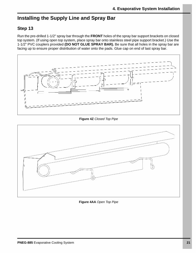
Run the pre-drilled 1-1/2" spray bar through the FRONT holes of the spray bar support brackets on closed top system. (If using open top system, place spray bar onto stainless steel pipe support bracket.) Use the 1-1/2" PVC couplers provided (DO NOT GLUE SPRAY BAR). Be sure that all holes in the spray bar are facing up to ensure proper distribution of water onto the pads. Glue cap on end of last spray bar.
Figure 4Z Closed Top Pipe
Figure 4AA Open Top Pipe
4. Evaporative System Installation
22 PNEG-885 Evaporative Cooling System
End Panel Assembly Installation
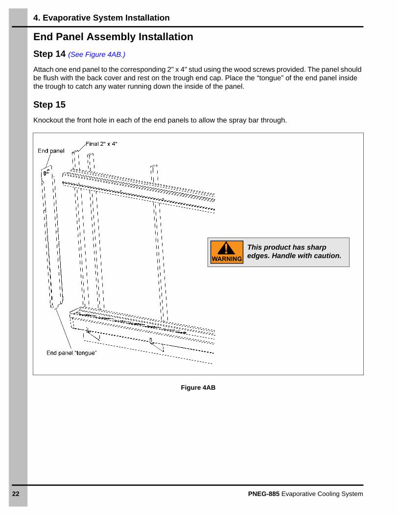
Step 14 (See Figure 4AB.)
Attach one end panel to the corresponding 2" x 4" stud using the wood screws provided. The panel should be flush with the back cover and rest on the trough end cap. Place the “tongue” of the end panel inside the trough to catch any water running down the inside of the panel.
Step 15
Knockout the front hole in each of the end panels to allow the spray bar through.
Figure 4AB
WARNING
This product has sharp edges. Handle with caution.
4. Evaporative System Installation
PNEG-885 Evaporative Cooling System 23
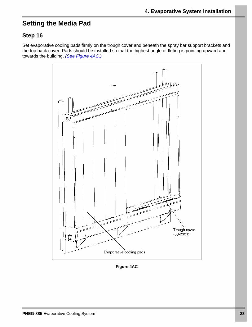
Setting the Media Pad
Step 16
Set evaporative cooling pads firmly on the trough cover and beneath the spray bar support brackets and the top back cover. Pads should be installed so that the highest angle of fluting is pointing upward and towards the building. (See Figure 4AC.)
Figure 4AC
4. Evaporative System Installation
24 PNEG-885 Evaporative Cooling System
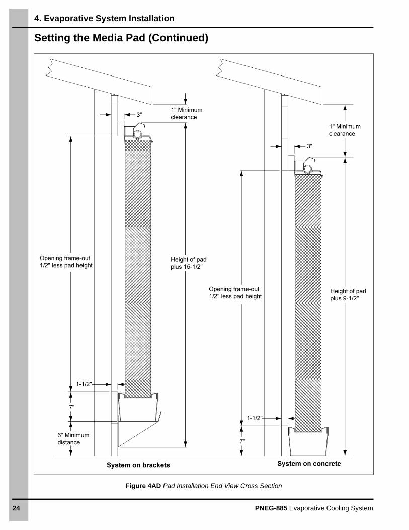
Setting the Media Pad (Continued)
Figure 4AD Pad Installation End View Cross Section
4. Evaporative System Installation
PNEG-885 Evaporative Cooling System 25
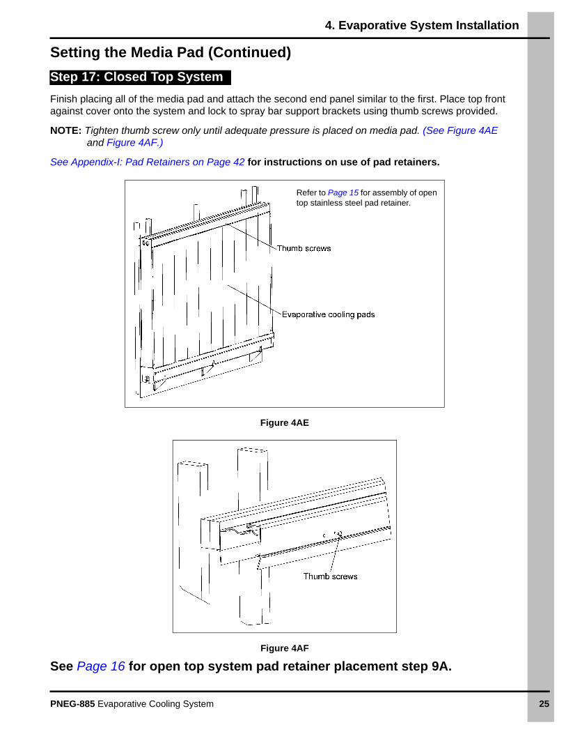
Setting the Media Pad (Continued)
Step 17: Closed Top System
Finish placing all of the media pad and attach the second end panel similar to the first. Place top front against cover onto the system and lock to spray bar support brackets using thumb screws provided.
NOTE: Tighten thumb screw only until adequate pressure is placed on media pad. (See Figure 4AE and Figure 4AF.)
See Appendix-I: Pad Retainers on Page 42 for instructions on use of pad retainers.
Figure 4AE
Figure 4AF
See Page 16 for open top system pad retainer placement step 9A.
Refer to Page 15 for assembly of open top stainless steel pad retainer.
4. Evaporative System Installation
26 PNEG-885 Evaporative Cooling System
Installing the Reservoir Tank
Step 18
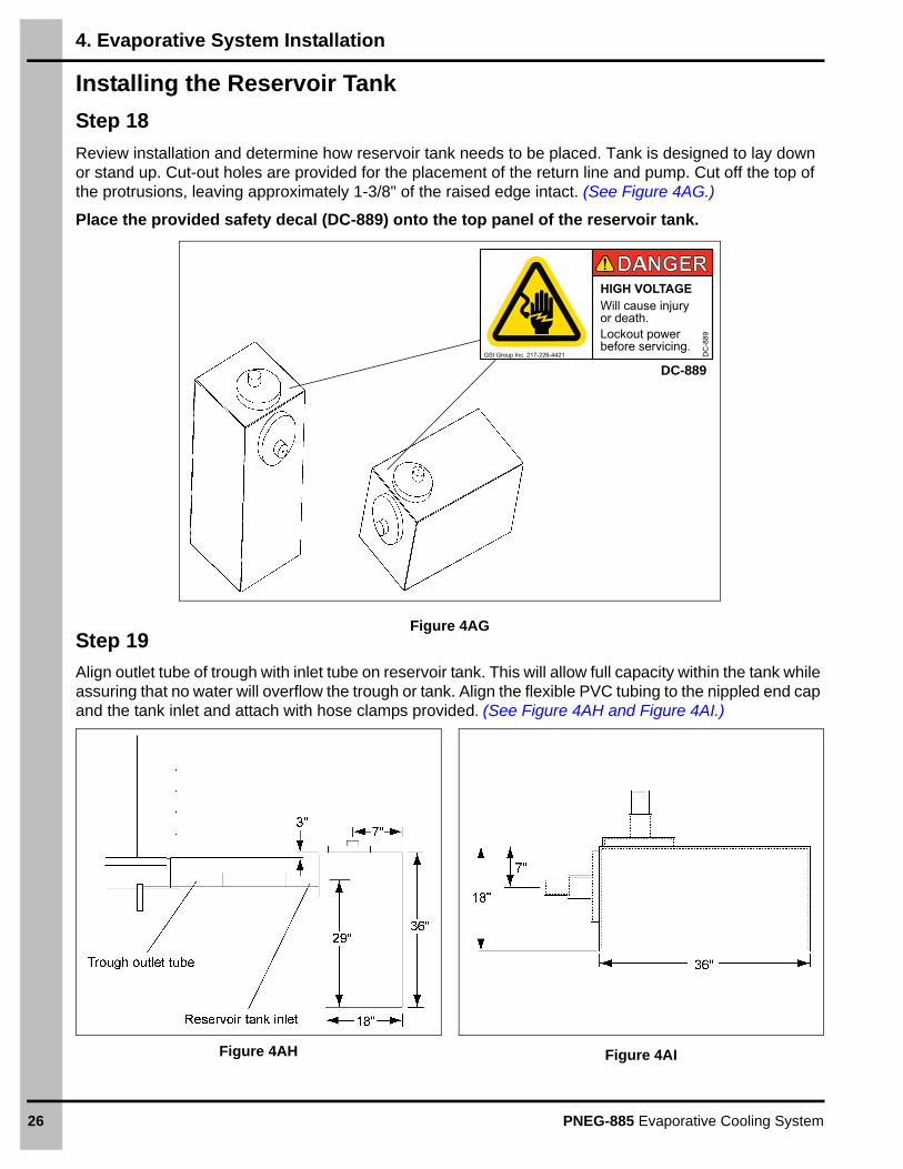
Review installation and determine how reservoir tank needs to be placed. Tank is designed to lay down or stand up. Cut-out holes are provided for the placement of the return line and pump. Cut off the top of the protrusions, leaving approximately 1-3/8" of the raised edge intact. (See Figure 4AG.)
Place the provided safety decal (DC-889) onto the top panel of the reservoir tank.
Figure 4AG Step 19
Align outlet tube of trough with inlet tube on reservoir tank. This will allow full capacity within the tank while assuring that no water will overflow the trough or tank. Align the flexible PVC tubing to the nippled end cap and the tank inlet and attach with hose clamps provided. (See Figure 4AH and Figure 4AI.)
Figure 4AH Figure 4AI
DANGERDANGERHIGH VOLTAGEWill cause injuryor death.Lockout powerbefore servicing.
DC
-889
GSI Group Inc. 217-226-4421
DC-889
4. Evaporative System Installation
PNEG-885 Evaporative Cooling System 27
Installing the Vertical Piping Assembly
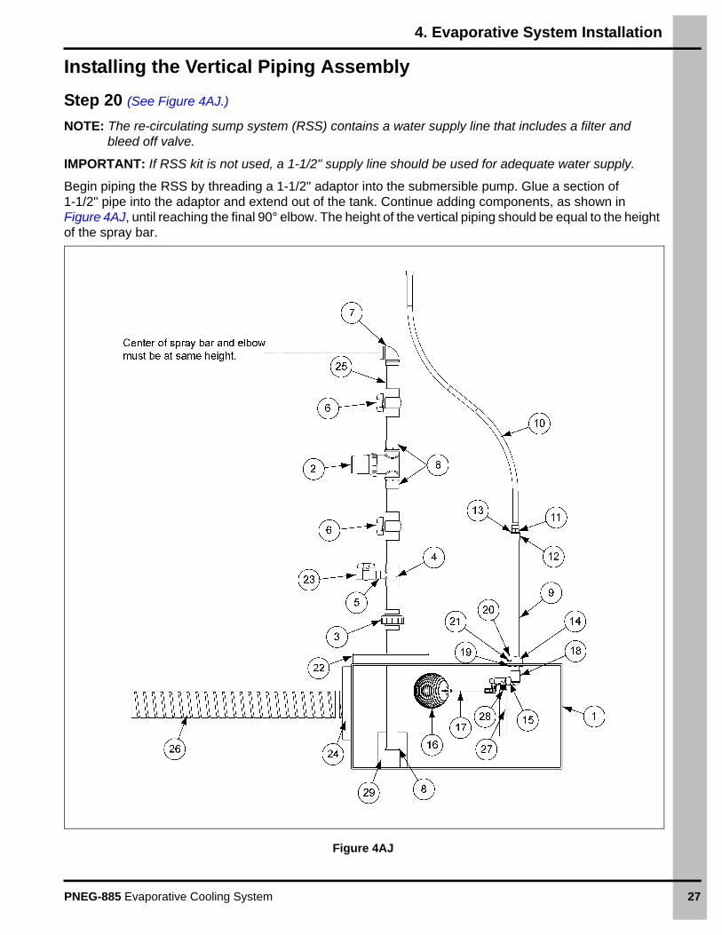
Step 20 (See Figure 4AJ.)
NOTE: The re-circulating sump system (RSS) contains a water supply line that includes a filter and bleed off valve.
IMPORTANT: If RSS kit is not used, a 1-1/2" supply line should be used for adequate water supply.
Begin piping the RSS by threading a 1-1/2" adaptor into the submersible pump. Glue a section of 1-1/2" pipe into the adaptor and extend out of the tank. Continue adding components, as shown in Figure 4AJ, until reaching the final 90° elbow. The height of the vertical piping should be equal to the height of the spray bar.
Figure 4AJ
4. Evaporative System Installation
28 PNEG-885 Evaporative Cooling System
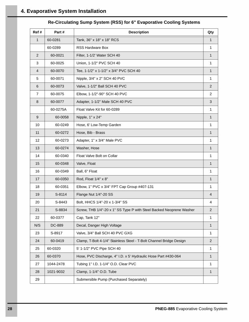
Re-Circulating Sump System (RSS) for 6" Evaporative Cooling Systems
Ref # Part # Description Qty
1 60-0281 Tank, 36" x 18" x 18" RCS 1
60-0289 RSS Hardware Box 1
2 60-0021 Filter, 1-1/2' Water SCH 40 1
3 60-0025 Union, 1-1/2" PVC SCH 40 1
4 60-0070 Tee, 1-1/2" x 1-1/2" x 3/4" PVC SCH 40 1
5 60-0071 Nipple, 3/4" x 2" SCH 40 PVC 1
6 60-0073 Valve, 1-1/2" Ball SCH 40 PVC 2
7 60-0075 Elbow, 1-1/2"-90° SCH 40 PVC 2
8 60-0077 Adapter, 1-1/2" Male SCH 40 PVC 3
60-0275A Float Valve Kit for 60-0289 1
9 60-0058 Nipple, 1" x 24" 1
10 60-0249 Hose, 6' Low-Temp Garden 1
11 60-0272 Hose, Bib - Brass 1
12 60-0273 Adapter, 1" x 3/4" Male PVC 1
13 60-0274 Washer, Hose 1
14 60-0340 Float Valve Bolt on Collar 1
15 60-0348 Valve, Float 1
16 60-0349 Ball, 6" Float 1
17 60-0350 Rod, Float 1/4" x 8" 1
18 60-0351 Elbow, 1" PVC x 3/4" FPT Cap Group #407-131 1
19 S-8114 Flange Nut 1/4"-20 SS 4
20 S-8443 Bolt, HHCS 1/4"-20 x 1-3/4" SS 4
21 S-8834 Screw, THB 1/4"-20 x 1" SS Type P with Steel Backed Neoprene Washer 2
22 60-0377 Cap, Tank 12" 1
N/S DC-889 Decal, Danger High Voltage 1
23 S-8917 Valve, 3/4" Ball SCH 40 PVC GXG 1
24 60-0419 Clamp, T-Bolt 4-1/4" Stainless Steel - T-Bolt Channel Bridge Design 2
25 60-0320 5' 1-1/2" PVC Pipe SCH 40 1
26 60-0370 Hose, PVC Discharge, 4" I.D. x 5' Hydraulic Hose Part #430-064 1
27 1044-2478 Tubing 1" I.D. 1-1/4" O.D. Clear PVC 1
28 1021-9032 Clamp, 1-1/4" O.D. Tube 1
29 Submersible Pump (Purchased Separately)
4. Evaporative System Installation
PNEG-885 Evaporative Cooling System 29
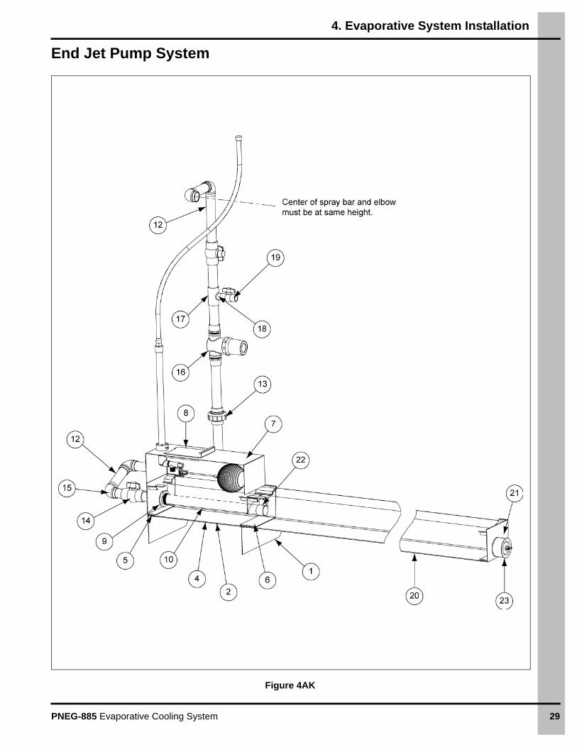
End Jet Pump System
Figure 4AK
4. Evaporative System Installation
30 PNEG-885 Evaporative Cooling System
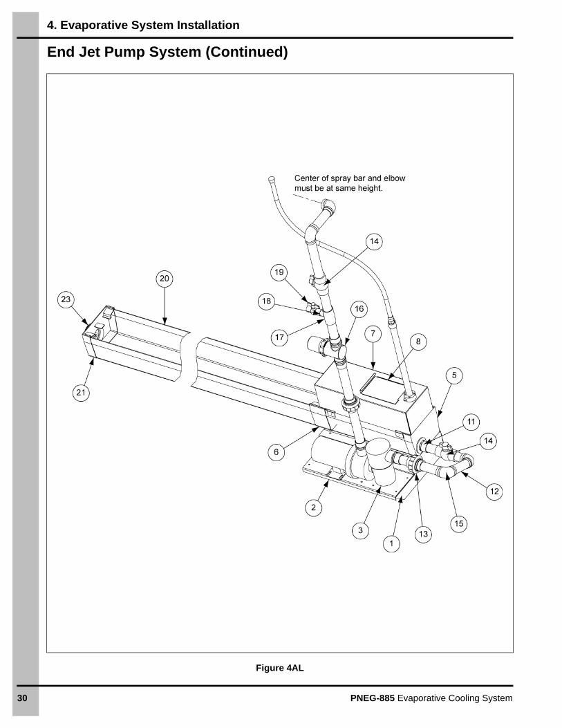
End Jet Pump System (Continued)
Figure 4AL
4. Evaporative System Installation
PNEG-885 Evaporative Cooling System 31
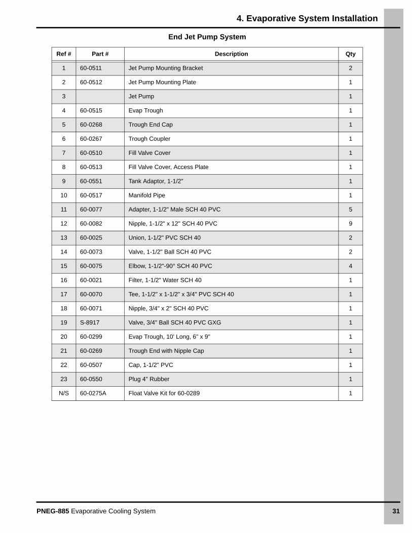
End Jet Pump System
Ref # Part # Description Qty
1 60-0511 Jet Pump Mounting Bracket 2
2 60-0512 Jet Pump Mounting Plate 1
3 Jet Pump 1
4 60-0515 Evap Trough 1
5 60-0268 Trough End Cap 1
6 60-0267 Trough Coupler 1
7 60-0510 Fill Valve Cover 1
8 60-0513 Fill Valve Cover, Access Plate 1
9 60-0551 Tank Adaptor, 1-1/2" 1
10 60-0517 Manifold Pipe 1
11 60-0077 Adapter, 1-1/2" Male SCH 40 PVC 5
12 60-0082 Nipple, 1-1/2" x 12" SCH 40 PVC 9
13 60-0025 Union, 1-1/2" PVC SCH 40 2
14 60-0073 Valve, 1-1/2" Ball SCH 40 PVC 2
15 60-0075 Elbow, 1-1/2"-90° SCH 40 PVC 4
16 60-0021 Filter, 1-1/2" Water SCH 40 1
17 60-0070 Tee, 1-1/2" x 1-1/2" x 3/4" PVC SCH 40 1
18 60-0071 Nipple, 3/4" x 2" SCH 40 PVC 1
19 S-8917 Valve, 3/4" Ball SCH 40 PVC GXG 1
20 60-0299 Evap Trough, 10' Long, 6" x 9" 1
21 60-0269 Trough End with Nipple Cap 1
22 60-0507 Cap, 1-1/2" PVC 1
23 60-0550 Plug 4" Rubber 1
N/S 60-0275A Float Valve Kit for 60-0289 1
4. Evaporative System Installation
32 PNEG-885 Evaporative Cooling System
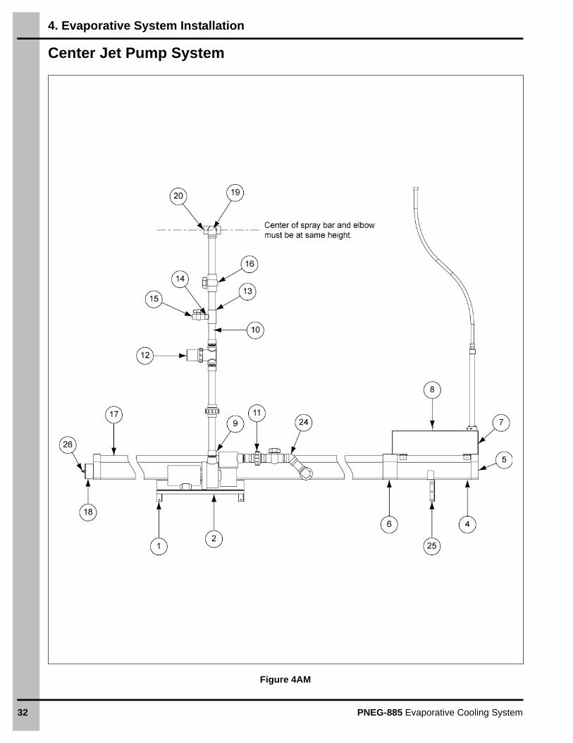
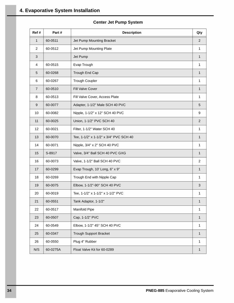
Center Jet Pump System
Figure 4AM
4. Evaporative System Installation
PNEG-885 Evaporative Cooling System 33
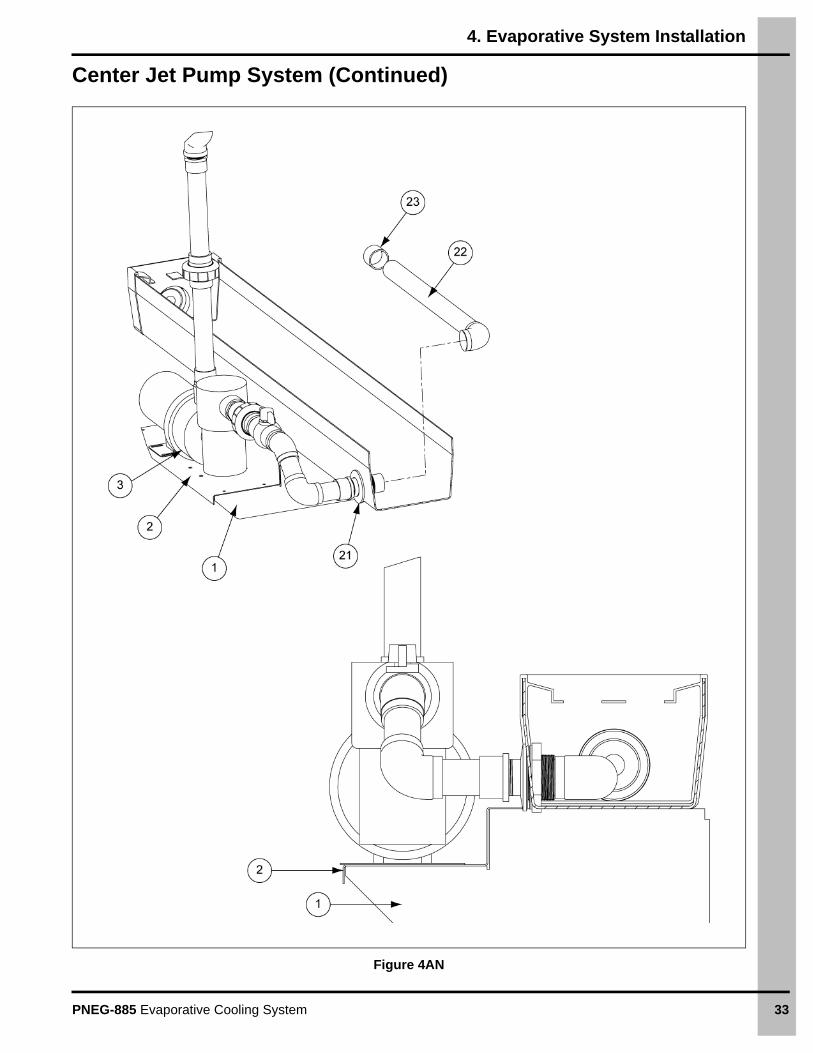
Center Jet Pump System (Continued)
Figure 4AN
4. Evaporative System Installation
34 PNEG-885 Evaporative Cooling System
Center Jet Pump System
Ref # Part # Description Qty
1 60-0511 Jet Pump Mounting Bracket 2
2 60-0512 Jet Pump Mounting Plate 1
3 Jet Pump 1
4 60-0515 Evap Trough 1
5 60-0268 Trough End Cap 1
6 60-0267 Trough Coupler 1
7 60-0510 Fill Valve Cover 1
8 60-0513 Fill Valve Cover, Access Plate 1
9 60-0077 Adapter, 1-1/2" Male SCH 40 PVC 5
10 60-0082 Nipple, 1-1/2" x 12" SCH 40 PVC 9
11 60-0025 Union, 1-1/2" PVC SCH 40 2
12 60-0021 Filter, 1-1/2" Water SCH 40 1
13 60-0070 Tee, 1-1/2" x 1-1/2" x 3/4" PVC SCH 40 1
14 60-0071 Nipple, 3/4" x 2" SCH 40 PVC 1
15 S-8917 Valve, 3/4" Ball SCH 40 PVC GXG 1
16 60-0073 Valve, 1-1/2" Ball SCH 40 PVC 2
17 60-0299 Evap Trough, 10' Long, 6" x 9" 1
18 60-0269 Trough End with Nipple Cap 1
19 60-0075 Elbow, 1-1/2"-90° SCH 40 PVC 3
20 60-0019 Tee, 1-1/2" x 1-1/2" x 1-1/2" PVC 1
21 60-0551 Tank Adaptor, 1-1/2" 1
22 60-0517 Manifold Pipe 1
23 60-0507 Cap, 1-1/2" PVC 1
24 60-0549 Elbow, 1-1/2" 45° SCH 40 PVC 1
25 60-0347 Trough Support Bracket 1
26 60-0550 Plug 4" Rubber 1
N/S 60-0275A Float Valve Kit for 60-0289 1
4. Evaporative System Installation
PNEG-885 Evaporative Cooling System 35
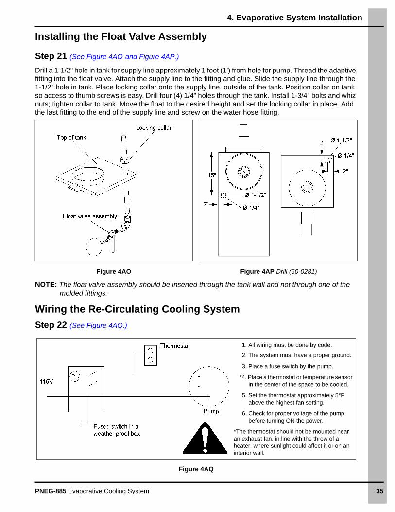
Installing the Float Valve Assembly
Step 21 (See Figure 4AO and Figure 4AP.)
Drill a 1-1/2" hole in tank for supply line approximately 1 foot (1') from hole for pump. Thread the adaptive fitting into the float valve. Attach the supply line to the fitting and glue. Slide the supply line through the 1-1/2" hole in tank. Place locking collar onto the supply line, outside of the tank. Position collar on tank so access to thumb screws is easy. Drill four (4) 1/4" holes through the tank. Install 1-3/4" bolts and whiz nuts; tighten collar to tank. Move the float to the desired height and set the locking collar in place. Add the last fitting to the end of the supply line and screw on the water hose fitting.
Figure 4AO Figure 4AP Drill (60-0281)
NOTE: The float valve assembly should be inserted through the tank wall and not through one of the molded fittings.
Wiring the Re-Circulating Cooling System
Step 22 (See Figure 4AQ.)
Figure 4AQ
1. All wiring must be done by code.
2. The system must have a proper ground.
3. Place a fuse switch by the pump.
*4. Place a thermostat or temperature sensor in the center of the space to be cooled.
5. Set the thermostat approximately 5°F above the highest fan setting.
6. Check for proper voltage of the pump before turning ON the power.
*The thermostat should not be mounted near an exhaust fan, in line with the throw of a heater, where sunlight could affect it or on an interior wall.
36 PNEG-885 Evaporative Cooling System
5. Operation and Maintenance of the Re-Circulating Cooling System
Initial Start-Up New Media
Inspect for Air Leaks
To obtain the most efficient cooling available, it is important that all air flows through the pad. Since air takes the path of least resistance, any leaks around curtain, exhaust fans, door, etc., will let air bypass the pad and will dilute cooled air with warm outside air. This will cause a temperature increase throughout the house.
Allow Break-in Period
The new pad has a slick surface and wets out more slowly than a pad that has been in use for some time. After installation, run water continuously over the pad for one to two days. To wet out the pad faster, add a small amount of surfactants to the water supply. Spreader-sticker type agricultural surfactants are available through supply houses and hardware stores.
Check for Dry Streaks
Dry streaks on the pad indicate problems with the water distribution system. Usually a minor adjustment in the direction of distribution holes will correct the problem. Also, check distribution holes for debris. Clear any plugged holes by inserting a rod or dowel into the hole.
Adjust Water Bleed Off Rate
It is important that a constant amount of re-circulating water is drained from the system during its operation. This prevents concentration of dissolved solids that may stick to the pad. Accumulation of deposits will restrict air flow through the pad.
Normal Operation
Run Pump Constantly
It is best to run the pump constantly during the cooling season, unless the water source is very soft. Allowing the pump to cycle ON and OFF for short durations increases the rate at which deposits will accumulate on the pad.
Daily Shut Down
At the end of each cooling day, allow the fans to run 30 minutes or longer after the pump is shut down. This helps dry out the pad which prevents the growth of bacteria or fungus that can plug filter and distribution holes.
Maintain Bleed Off
Periodically check for dry spots and to ensure that bleed off function is operational. Well-meaning personnel many times misinterpret dribbling water as a leak and turn OFF the valve. If necessary, attach a warning sign to the bleed off valve.
Proper Water Levels
Do not over fill the system with water. If the water level is too high, the bottom of the media may sit in water at all times and become waterlogged. This also can threaten the pad’s self-supporting status and shorten its life.
5. Operation and Maintenance of the Re-Circulating Cooling System
PNEG-885 Evaporative Cooling System 37
Annual Shut Down and Start-Up Process
Annual Shut Down
At the end of each cooling season, winterize the system. This permits a quick start-up with minimal repairs when the system is again placed in operation.
Drain the System
Allowing water to freeze within the system can cause serious damage. Winterizing the system simply involves draining all pumps, water collection troughs and holding tanks. Even if freezing is not a problem, water allowed to remain in the system can accumulate sediment, algae or bacteria and will plug pump screens and distribution holes when the system is started again.
Close Valves and Seal Large Holes
Pump intakes and other large openings to the system should be properly sealed. Rats, frogs, snails, lizards and insects have been found inside water distribution systems and their presence can result in restricted water flow or damage to pumps and other components.
Annual Start-Up
When starting the new cooling season, the following procedures will help ensure that the system is clean.
Inspect the System Thoroughly
Make a complete visual inspection of pump screens and filters for dirt and other foreign matter including birds and rodents, or their nests. This inspection should be completed before water is added to the system.
Perform Test Run
Fill the tank and run the pump for one or two hours. Shut down the system and recheck all screens, pumps and filters for trash or other refuse.
Adjust Water Bleed Off
Refer to the water chemistry portion of the maintenance section on Page 38.
Algae/Bacteria Control
Control without Chemicals
Most organisms thrive in the presence of water, sunlight and nutrients.
Allowing the media to dry at the end of each cooling day eliminates the moisture problem and the organisms become flaky or powdery. When the system is started the next day, the small dry flakes are washed out and trapped in the filter. Large flakes or deposits can be brushed or vacuumed from dry pads. This method is used to control algae in most agricultural operations.
To solve the sunlight problem, use dark louvers or curtains to shade the pad. Make sure airflow is not impeded.
All nutrients and fertilizers should be kept away from the pad. In greenhouse applications, never spray liquid fertilizer on the pad. Most chemicals that contain phosphorus or phosphate compounds will promote organism growth.
5. Operation and Maintenance of the Re-Circulating Cooling System
38 PNEG-885 Evaporative Cooling System
Control with Chemicals
There are numerous products and methods available for chemical control of organisms. This section covers some basic ideas about their application.
Always exercise extreme caution when using any chemicals to control the growth of organisms. Harsh chemicals can damage the media and other system components and can be harmful to humans. Handle chemical defoliants carefully. Start with very low concentrations and gradually increase application amount to effective levels. Overuse of chemicals can damage the system.
The most commonly used chemical for organism control is chlorine. It is readily available and inexpensive, but it is also potentially dangerous. The only effective way to apply chlorine is to introduce it into the system on a continual basis on the pressure side of the pump. This can be done using a chemical injection pump that meters and adds a controlled amount each time the water re-circulates. Another application method is a basket type tablet holder installed on the pressure side of the pump.
NOTE: In final solution, 1 to 4 PPM free chlorine adequately controls organism growth. Higher rates of application may cause damage to the system and/or components. Use chlorine only if you can meter in these amounts. Up to three (3) times this concentration may be used in a garden type sprayer for an occasional shock treatment. Spray directly on the pad face, but only when organism growth is a serious problem and other methods are impractical. Always wear protective clothing and use proper eye and respiratory protection when spraying chlorine, or any other chemical.
Incorrect application of chemicals voids pad for warranties. Therefore, any chemical control program should be a coordinated effort that includes the system user, the chemical supplier and AP/Cumberland sales technicians.
Maintenance/Water Chemistry
Hard Water
Hard water contains a high amount of minerals, primarily calcium. A sample of water can contain only a specific amount of dissolved solids in solution. If these concentrations increase beyond a certain level, the excess minerals come out of solution.
Evaporation on cooling pads concentrates the minerals in solution and causes deposit buildup that can reduce airflow through the pad.
In most cases, bleeding off a portion of the re-circulating water (3% to 5%) and adding water to compensate for bleed off and evaporation will minimize mineral buildup on the pad.
The bleed off valve is placed on the pressure side between the pump and distribution header. A globe valve works well for regulating bleed off since it can be adjusted fairly accurately.
Soft Water
Soft water contains low concentrations of dissolved solids in solution and if used over extended periods of time may leach the stiffening agents from the pad. If water source provides soft water, minimize bleed off (less than 1%) or eliminate bleed off totality.
Regardless of the type of water used, the ideal final mineral concentration allows a slight white “frosting” to appear on the air entering face of the media over several months of operation. If water source is causing difficulty, contact an AP/Cumberland representative.
5. Operation and Maintenance of the Re-Circulating Cooling System
PNEG-885 Evaporative Cooling System 39
pH range:
Evaporative media provides optimal long life if the pH of the re-circulating water is between 6 and 9, which is normal for most water. If re-circulating water pH is outside this range, consult an AP/Cumberland sales technician.
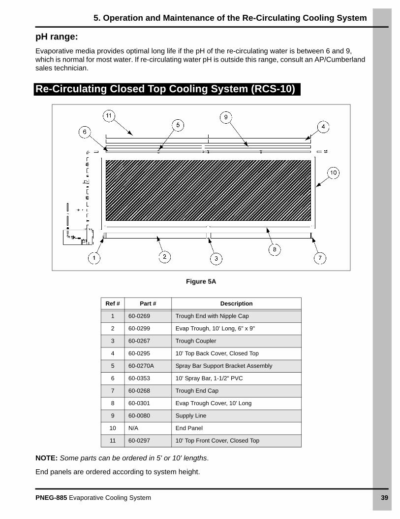
Re-Circulating Closed Top Cooling System (RCS-10)
Figure 5A
NOTE: Some parts can be ordered in 5' or 10' lengths.
End panels are ordered according to system height.
Ref # Part # Description
1 60-0269 Trough End with Nipple Cap
2 60-0299 Evap Trough, 10' Long, 6" x 9"
3 60-0267 Trough Coupler
4 60-0295 10' Top Back Cover, Closed Top
5 60-0270A Spray Bar Support Bracket Assembly
6 60-0353 10' Spray Bar, 1-1/2" PVC
7 60-0268 Trough End Cap
8 60-0301 Evap Trough Cover, 10' Long
9 60-0080 Supply Line
10 N/A End Panel
11 60-0297 10' Top Front Cover, Closed Top
5. Operation and Maintenance of the Re-Circulating Cooling System
40 PNEG-885 Evaporative Cooling System
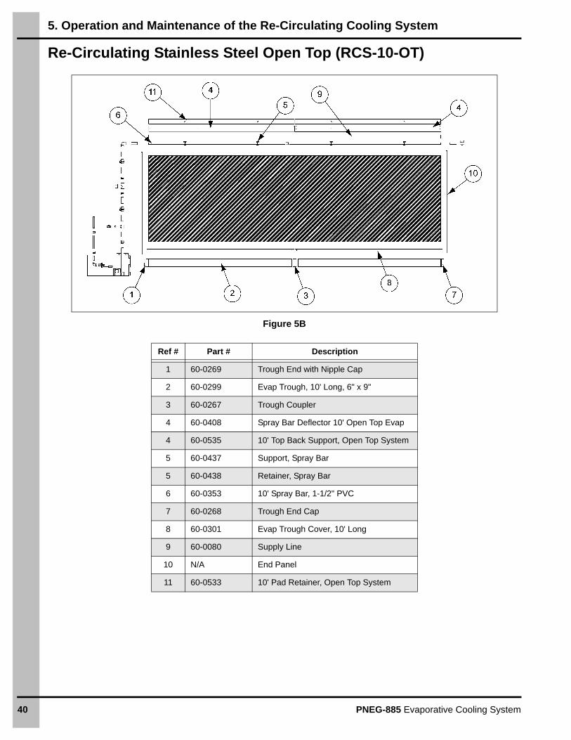
Re-Circulating Stainless Steel Open Top (RCS-10-OT)
Figure 5B
Ref # Part # Description
1 60-0269 Trough End with Nipple Cap
2 60-0299 Evap Trough, 10' Long, 6" x 9"
3 60-0267 Trough Coupler
4 60-0408 Spray Bar Deflector 10' Open Top Evap
4 60-0535 10' Top Back Support, Open Top System
5 60-0437 Support, Spray Bar
5 60-0438 Retainer, Spray Bar
6 60-0353 10' Spray Bar, 1-1/2" PVC
7 60-0268 Trough End Cap
8 60-0301 Evap Trough Cover, 10' Long
9 60-0080 Supply Line
10 N/A End Panel
11 60-0533 10' Pad Retainer, Open Top System
5. Operation and Maintenance of the Re-Circulating Cooling System
PNEG-885 Evaporative Cooling System 41
Re-Circulating Aluminum Open Top (RCS-10-OTA)
Ref # Part # Description
1 60-0269 Trough End with Nipple Cap
2 60-0299 Evap Trough, 10' Long, 6" x 9"
3 60-0267 Trough Coupler
4 60-0520 Spray Bar Deflector 10' Open Top Evap
4 60-0522 10' Top Back Support, Open Top System
5 60-0437 Support, Spray Bar
5 60-0438 Retainer, Spray Bar
6 60-0353 10' Spray Bar, 1-1/2" PVC
7 60-0268 Trough End Cap
8 60-0301 Evap Trough Cover, 10' Long
9 60-0080 Supply Line
10 N/A End Panel - Various per Size of System
11 60-0519 10' Pad Retainer, Open Top System
42 PNEG-885 Evaporative Cooling System
6. Appendix-I: Pad Retainers
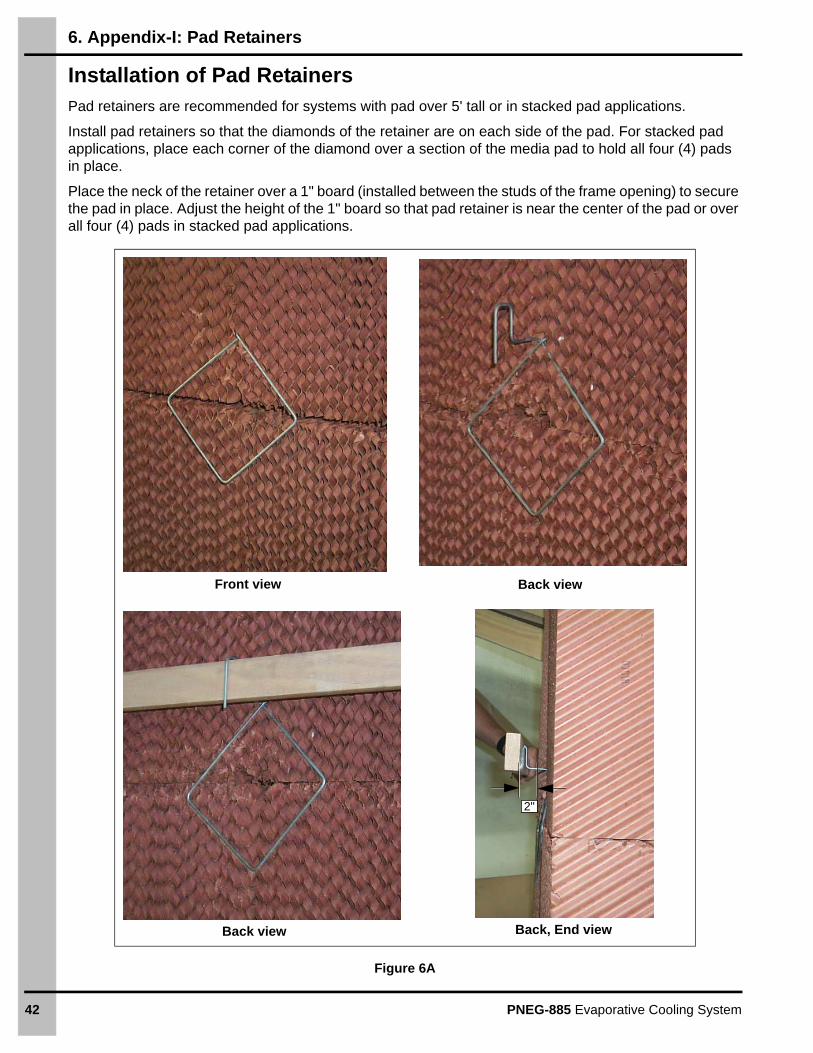
Installation of Pad RetainersPad retainers are recommended for systems with pad over 5' tall or in stacked pad applications.
Install pad retainers so that the diamonds of the retainer are on each side of the pad. For stacked pad applications, place each corner of the diamond over a section of the media pad to hold all four (4) pads in place.
Place the neck of the retainer over a 1" board (installed between the studs of the frame opening) to secure the pad in place. Adjust the height of the 1" board so that pad retainer is near the center of the pad or over all four (4) pads in stacked pad applications.
Figure 6A
Front view Back view
Back view Back, End view
2"
PNEG-885 Evaporative Cooling System 43
7. Appendix-II: Offset Support Brackets
RCS Evaporative Cooling Rough Opening
Framing the RCS with Offset Brackets
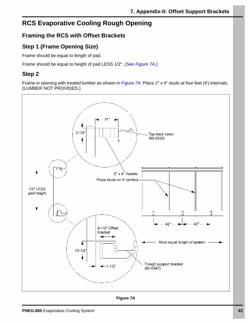
Step 1 (Frame Opening Size)
Frame should be equal to length of pad.
Frame should be equal to height of pad LESS 1/2". (See Figure 7A.)
Step 2
Frame in opening with treated lumber as shown in Figure 7A. Place 2" x 4" studs at four feet (4') intervals. (LUMBER NOT PROVIDED.)
Figure 7A
7. Appendix-II: Offset Support Brackets
44 PNEG-885 Evaporative Cooling System
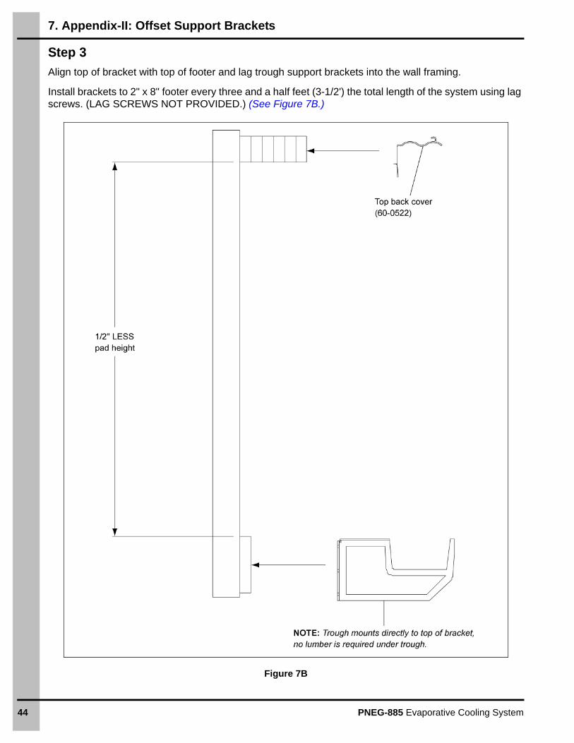
Step 3
Align top of bracket with top of footer and lag trough support brackets into the wall framing.
Install brackets to 2" x 8" footer every three and a half feet (3-1/2') the total length of the system using lag screws. (LAG SCREWS NOT PROVIDED.) (See Figure 7B.)
Figure 7B
PNEG-885 Evaporative Cooling System 45
8. Warranty
GSI Group, LLC Limited WarrantyThe GSI Group, LLC (“GSI”) warrants products which it manufactures to be free of defects in materials and workmanship under normal usage and conditions for a period of 12 months after sale to the original end-user or if a foreign sale, 14 months from arrival at port of discharge, whichever is earlier. The end-user’s sole remedy (and GSI’s only obligation) is to repair or replace, at GSI’s option and expense, products that in GSI’s judgment, contain a material defect in materials or workmanship. Expenses incurred by or on behalf of the end-user without prior written authorization from the GSI Warranty Group shall be the sole responsibility of the end-user.
Warranty Extensions:The Limited Warranty period is extended for the following products:
GSI further warrants that the portable and tower dryer frame and basket, excluding all auger and auger drive components, shall be free from defects in materials for a period of time beginning on the twelfth (12th) month from the date of purchase and continuing until the sixtieth (60th) month from the date of purchase (extended warranty period). During the extended warranty period, GSI will replace the frame or basket components that prove to be defective under normal conditions of use without charge, excluding the labor, transportation, and/or shipping costs incurred in the performance of this extended warranty.
Conditions and Limitations:THERE ARE NO WARRANTIES THAT EXTEND BEYOND THE LIMITED WARRANTY DESCRIPTION SET FORTH ABOVE. SPECIFICALLY, GSI MAKES NO FURTHER WARRANTY OF ANY KIND, EXPRESS OR IMPLIED, INCLUDING, WITHOUT LIMITATION, WARRANTIES OF MERCHANTABILITY OR FITNESS FOR A PARTICULAR PURPOSE OR USE IN CONNECTION WITH: (I) PRODUCT MANUFACTURED OR SOLD BY GSI OR (II) ANY ADVICE, INSTRUCTION, RECOMMENDATION OR SUGGESTION PROVIDED BY AN AGENT, REPRESENTATIVE OR EMPLOYEE OF GSI REGARDING OR RELATED TO THE CONFIGURATION, INSTALLATION, LAYOUT, SUITABILITY FOR A PARTICULAR PURPOSE, OR DESIGN OF SUCH PRODUCTS.
GSI shall not be liable for any direct, indirect, incidental or consequential damages, including, without limitation, loss of anticipated profits or benefits. The sole and exclusive remedy is set forth in the Limited Warranty, which shall not exceed the amount paid for the product purchased. This warranty is not transferable and applies only to the original end-user. GSI shall have no obligation or responsibility for any representations or warranties made by or on behalf of any dealer, agent or distributor.
GSI assumes no responsibility for claims resulting from construction defects or unauthorized modifications to products which it manufactured. Modifications to products not specifically delineated in the manual accompanying the equipment at initial sale will void the Limited Warranty.
This Limited Warranty shall not extend to products or parts which have been damaged by negligent use, misuse, alteration, accident or which have been improperly/inadequately maintained. This Limited Warranty extends solely to products manufactured by GSI.
Prior to installation, the end-user has the responsibility to comply with federal, state and local codes which apply to the location and installation of products manufactured or sold by GSI.
Product Warranty Period
AP Fans and Flooring
Performer Series Direct Drive Fan Motor 3 Years* Warranty prorated from list price:
0 to 3 years - no cost to end-user
3 to 5 years - end-user pays 25%
5 to 7 years - end-user pays 50%
7 to 10 years - end-user pays 75%
** Warranty prorated from list price:
0 to 3 years - no cost to end-user
3 to 5 years - end-user pays 50%
† Motors, burner components and moving parts not included. Portable dryer screens included. Tower dryer screens not included.
All Fiberglass Housings Lifetime
All Fiberglass Propellers Lifetime
AP and Cumberland Flex-Flo/Pan Feeding System Motors 2 Years
Cumberland Feeding/Watering Systems
Feeder System Pan Assemblies 5 Years **
Feed Tubes (1-3/4" and 2.00") 10 Years *
Centerless Augers 10 Years *
Watering Nipples 10 Years *
Grain Systems Grain Bin Structural Design 5 Years
Grain SystemsFarm FansZimmerman
Portable and Tower Dryers 2 Years
Portable and Tower Dryer Frames and Internal Infrastructure †
5 Years
9101239_1_CR_rev8.DOC (revised January 2014)

Copyright © 2014 by GroupPrinted in the USA
This equipment shall be installed in accordance with the current installation codes and applicable
regulations, which should be carefully followed in all cases. Authorities having jurisdiction should be
consulted before installations are made.
1004 E. Illinois St. Assumption, IL 62510-0020
Phone: 1-217-226-4421 Fax: 1-217-226-4420
www.gsiag.com
CN-312964
AP/Cumberland is a part of GSI, a worldwide brand of AGCO Corporation.


![PASSIVE DOWNDRAUGHT EVAPORATIVE COOLING: The … · can be used to achieve thermal comfort. [1] Passive Downdraught Evaporative cooling (PDEC) Origin: Evaporative cooling has been](https://img.pdfslide.us/doc/110x75/5f835db0418ed251ad1ae1c3/passive-downdraught-evaporative-cooling-the-can-be-used-to-achieve-thermal-comfort.jpg)