Embed Size (px)
Citation preview

Cambium
PMP Synchronization
Solutions User Guide

pmp-0297 006v000 (February 2016)
Accuracy
While reasonable efforts have been made to assure the accuracy of this document, Cambium Networks assumes no liability resulting from any inaccuracies or omissions in this document, or from use of the
information obtained herein. Cambium reserves the right to make changes to any products described herein to
improve reliability, function, or design, and reserves the right to revise this document and to make changes from time to time in content hereof with no obligation to notify any person of revisions or changes. Cambium does not assume any liability arising out of the application or use of any product, software, or circuit described herein; neither does it convey license under its patent rights or the rights of others. It is possible that this publication may contain references to, or information about Cambium products (machines and programs), programming, or services that are not announced in your country. Such references or information must not be construed to mean that Cambium intends to announce such Cambium products, programming, or services in your country.
Copyrights
This document, Cambium products, and 3rd Party software products described in this document may include or describe copyrighted Cambium and other 3rd Party supplied computer programs stored in semiconductor memories or other media. Laws in the United States and other countries preserve for Cambium, its licensors, and other 3rd Party supplied software certain exclusive rights for copyrighted material, including the exclusive right to copy, reproduce in any form, distribute and make derivative works of the copyrighted material. Accordingly, any copyrighted material of Cambium, its licensors, or the 3rd Party software supplied material contained in the Cambium products described in this document may not be copied, reproduced, reverse engineered, distributed, merged or modified in any manner without the express written permission of Cambium. Furthermore, the purchase of Cambium products shall not be deemed to grant either directly or by implication, estoppel, or otherwise, any license under the copyrights, patents or patent applications of Cambium or other 3rd Party supplied software, except for the normal non-exclusive, royalty free license to use that arises by operation of law in the sale of a product.
Restrictions
Software and documentation are copyrighted materials. Making unauthorized copies is prohibited by law. No part of the software or documentation may be reproduced, transmitted, transcribed, stored in a retrieval system, or translated into any language or computer language, in any form or by any means, without prior written permission of Cambium.
License Agreements
The software described in this document is the property of Cambium and its licensors. It is furnished by express license agreement only and may be used only in accordance with the terms of such an agreement.
High Risk Materials
Components, units, or 3rd Party products used in the product described herein are NOT fault-tolerant and are NOT designed, manufactured, or intended for use as on-line control equipment in the following hazardous environments requiring fail-safe controls: the operation of Nuclear Facilities, Aircraft Navigation or Aircraft Communication Systems, Air Traffic Control, Life Support, or Weapons Systems (High Risk Activities). Cambium and its supplier(s) specifically disclaim any expressed or implied warranty of fitness for such High Risk Activities.
© 2016 Cambium Networks Limited. All Rights Reserved.

PMP Synchronization Solutions User Guide
pmp-0297 006v000 (February 2016) i
Safety and regulatory information
This section describes important safety and regulatory guidelines that must be observed by personnel installing or operating Cambium wireless equipment.
Important safety information
WARNING
To prevent loss of life or physical injury, observe the safety guidelines in this section.
Power lines
Exercise extreme care when working near power lines.
Working at heights
Exercise extreme care when working at heights.
Grounding and protective earth
Units must be properly grounded to protect against lightning. It is the user’s responsibility to install the
equipment in accordance with national regulations. In the USA, follow Section 810 of the National Electric
Code, ANSI/NFPA No.70-1984 (USA). In Canada, follow Section 54 of the Canadian Electrical Code.
These codes describe correct installation procedures for grounding the outdoor unit, mast, lead-in wire
and discharge unit, size of grounding conductors and connection requirements for grounding electrodes.
Other regulations may apply in different countries and therefore it is recommended that installation of the
outdoor unit be contracted to a professional installer.
Powering down before servicing
Always power down and unplug the equipment before servicing.
Primary disconnect device
The AP, SM, or BHs unit’s power supply is the primary disconnect device.
External cables
Safety may be compromised if outdoor rated cables are not used for connections that will be exposed to
the outdoor environment.

PMP Synchronization Solutions User Guide
pmp-0297 006v000 (February 2016) ii
RF exposure near the antenna
Radio frequency (RF) fields will be present close to the antenna when the transmitter is on. Always turn
off the power to the unit before undertaking maintenance activities in front of the antenna.
Minimum separation distances
Install the AP/SM/BH so as to provide and maintain the minimum separation distances from all persons.
The minimum separation distances for each frequency variant are specified in the product’s
corresponding User Guide.

PMP Synchronization Solutions User Guide
pmp-0297 006v000 (February 2016) iii
Contents
Safety and regulatory information ............................................................................................ i
Important safety information .......................................................................................................................... i
General information ............................................................................................................................................ ix
Version information ...................................................................................................................................... ix
Contacting Cambium Networks ................................................................................................................... ix
Caring for the environment .................................................................................................................................. x
Chapter 1: Introduction to synchronization ....................................................................... 1-1
Interference and reliability ............................................................................................................................... 1-2
Exclusivity and free use of spectrum ........................................................................................................ 1-2
Sources of interference ............................................................................................................................ 1-3
Neutralizing interference .................................................................................................................................. 1-4
GPS synchronization ................................................................................................................................ 1-4
Configuration options for TDD synchronization ........................................................................................ 1-5
Alternative to GPS synchronization .......................................................................................................... 1-6
Cambium’s synchronization solutions ............................................................................................................. 1-7
Universal GPS (UGPS) ............................................................................................................................ 1-7
CMM4 (Rack Mount) ................................................................................................................................ 1-7
CMMmicro (CMM3) .................................................................................................................................. 1-8
CMM4 (Cabinet with switch) ................................................................................................................... 1-8
CMM4 (Cabinet without switch) .............................................................................................................. 1-8
Chapter 2: Cambium Cluster Management Module (CMM) .................................................... 2-1
CMM4 and Controller Board ............................................................................................................................ 2-2
Power ............................................................................................................................................................... 2-6
Ethernet Switch ............................................................................................................................................... 2-7
Specifications .................................................................................................................................................. 2-8
Providing sync to CMM via UGPS Module .................................................................................................... 2-10
CMM Planning ............................................................................................................................................... 2-11
Typical Ethernet Cabling ........................................................................................................................ 2-11
Standard Ethernet Cabling Configuration ............................................................................................... 2-11
Power Planning ....................................................................................................................................... 2-16
Syncing Two Co-located CMMs Together .............................................................................................. 2-18
Cables ..................................................................................................................................................... 2-20
EtherWAN Switch Information ....................................................................................................................... 2-24
Configuring a CMM4 ...................................................................................................................................... 2-26
Configuring IP Communications Parameters ......................................................................................... 2-26
Overriding Forgotten IP Addresses, Usernames, or Passwords ............................................................ 2-27
Log In ...................................................................................................................................................... 2-30
User Update ............................................................................................................................................ 2-31
PMP Synchronization Solutions User Guide
pmp-0297 006v000 (February 2016) iv
Add User ................................................................................................................................................. 2-32
Delete User ............................................................................................................................................. 2-33
Configuring the CMM4 ports ................................................................................................................... 2-33
Configuring General CMM4 Parameters ................................................................................................ 2-34
Configuring the SNMP parameters ......................................................................................................... 2-36
Configuring VLAN ................................................................................................................................... 2-38
Configuring the Unit Settings .................................................................................................................. 2-39
Viewing the ARP Table (Statistics) ......................................................................................................... 2-40
Viewing General Status .......................................................................................................................... 2-41
Viewing Sync Status ............................................................................................................................... 2-44
Viewing the System Log ......................................................................................................................... 2-45
Viewing the Network Interface ................................................................................................................ 2-46
Viewing Layer 2 neighbors ..................................................................................................................... 2-46
Installing a CMM4 .......................................................................................................................................... 2-47
Avoiding hazards .................................................................................................................................... 2-47
Grounding Equipment ............................................................................................................................. 2-47
Conforming to Regulations ..................................................................................................................... 2-48
Protecting Cables and Connections ....................................................................................................... 2-48
Testing the Components ........................................................................................................................ 2-48
Unpacking Components ......................................................................................................................... 2-48
Cables ..................................................................................................................................................... 2-48
Installing a GPS Antenna ....................................................................................................................... 2-48
Installing the power supply for the CMM4 (30 VDC or 54 VDC) ............................................................ 2-52
Temperature Range................................................................................................................................ 2-57
Installing a CMM4 (Models 1090CKHH and 1091HH) ........................................................................... 2-57
Installing a Rackmount CMM4 (Model 1092HH) .................................................................................... 2-59
Cabling a CMM4 (Models 1090CKHH and 1091HH) ............................................................................. 2-60
Cabling a Rackmount CMM4 .................................................................................................................. 2-64
Power Faults ........................................................................................................................................... 2-66
Chapter 3: Universal Global Positioning System Module ...................................................... 3-1
UGPS Product Description and Overview ....................................................................................................... 3-2
UGPS Power Source Configurations .............................................................................................................. 3-4
External Power Only ................................................................................................................................. 3-4
Power from the Radio via UGPS Timing Port 1 or UGPS Timing Port 2 ................................................. 3-8
UGPS and CMM Configurations ................................................................................................................... 3-14
Product Specifications ................................................................................................................................... 3-15
UGPS installation and operation ................................................................................................................... 3-16
UGPS Installation Procedure......................................................................................................................... 3-18
IP default bypass ........................................................................................................................................... 3-22
GPS status and location data readout ........................................................................................................... 3-24
Retrieving GPS Status and Location Data via Radio Web Management GUI ....................................... 3-24
Retrieving GPS status and location data via SNMP ............................................................................... 3-25
UGPS Power Port and Timing Port Pinouts .................................................................................................. 3-28
Chapter 4: CMM Regulatory and Legal Notices .................................................................. 4-1

PMP Synchronization Solutions User Guide
pmp-0297 006v000 (February 2016) v
Important Note on Modifications ............................................................................................................... 4-1
National and Regional Regulatory Notices ...................................................................................................... 4-2
U.S. Federal Communication Commission (FCC) Notification ................................................................. 4-2
Industry Canada (IC) Notification ............................................................................................................. 4-2
Equipment Disposal .................................................................................................................................. 4-3
EU Declaration of Conformity for RoHS Compliance ............................................................................... 4-3
Labeling and Disclosure Table for China ................................................................................................. 4-3
RF Exposure Separation Distances ................................................................................................................ 4-5
Legal Notices ................................................................................................................................................... 4-6
Software License Terms and Conditions .................................................................................................. 4-6
Hardware Warranty in U.S. ....................................................................................................................... 4-9
Limit of Liability ......................................................................................................................................... 4-9
Chapter 5: UGPS Regulatory, Legal, and Safety Notices ...................................................... 5-1
IMPORTANT NOTE ON MODIFICATIONS ............................................................................................. 5-1
Universal GPS module label ..................................................................................................................... 5-1
NATIONAL AND REGIONAL REGULATORY NOTICES ........................................................................ 5-1
Equipment Disposal .................................................................................................................................. 5-3
LIMIT OF LIABILITY ................................................................................................................................. 5-3

PMP Synchronization Solutions User Guide
pmp-0297 006v000 (February 2016) vi
List of Figures
Figure 1 GPS Synchronization ............................................................................................................................. 1-4
Figure 2 One unsynchronized AP in cluster resulting in self-interference ............................................................ 1-6
Figure 3 CMM4 internal view, including cable glands ........................................................................................... 2-3
Figure 4 Rackmount CMM4 .................................................................................................................................. 2-4
Figure 5 GPS Antenna.......................................................................................................................................... 2-5
Figure 6 CMM4 Standard Configuration ............................................................................................................. 2-12
Figure 7 Rackmount CMM4 Standard Configuration ......................................................................................... 2-12
Figure 8 CMM4 cabled to use Gigabit Ethernet feed ......................................................................................... 2-14
Figure 9 CMM4 cabled to support PTP 500/600 ................................................................................................ 2-15
Figure 10 Location of pin 1 ................................................................................................................................. 2-21
Figure 11 CMM sync cable pinout ...................................................................................................................... 2-23
Figure 12 Location of pin 1 ................................................................................................................................. 2-23
Figure 13 IP tab of CMM4................................................................................................................................... 2-26
Figure 14 Login page of CMM4 .......................................................................................................................... 2-30
Figure 15 Changer Users Password tab of CMM4 ............................................................................................. 2-31
Figure 16 Add User tab of CMM4 ....................................................................................................................... 2-32
Figure 17 Delete User tab of CMM4 ................................................................................................................... 2-33
Figure 18 Port Configuration tab of CMM4 ......................................................................................................... 2-33
Figure 19 CMM4 Configuration tab .................................................................................................................... 2-34
Figure 20 SNMP tab of CMM4 ........................................................................................................................... 2-36
Figure 21 VLAN tab of CMM4 ............................................................................................................................ 2-38
Figure 22 Unit Settings Tab of CMM4 ................................................................................................................ 2-39
Figure 23 ARP table ........................................................................................................................................... 2-40
Figure 24 General status tab of CMM4 .............................................................................................................. 2-41
Figure 25 Sync Status tab of CMM4 ................................................................................................................... 2-44
Figure 26 System Log tab of the CMM ............................................................................................................... 2-45
Figure 27 Network Interface tab of the CMM...................................................................................................... 2-46
Figure 28 Layer 2 Neighbors Log ....................................................................................................................... 2-46
Figure 29 Detail of GPS antenna mounting ........................................................................................................ 2-49
Figure 30 Weatherproofing an N-type antenna connector ................................................................................. 2-50
Figure 31 AP/BHM to UGPS cable ...................................................................................................................... 2-51
Figure 32 Power supply DC connection ............................................................................................................. 2-52
Figure 33 Power supply AC connection ............................................................................................................. 2-53
Figure 34 CMM4 line filter installation (EU only) ................................................................................................ 2-54
Figure 35 Rackmount CMM line filter installation (EU only) ............................................................................... 2-55
Figure 36 Resistor when using both 56 VDC and 30 VDC power ...................................................................... 2-57
Figure 37 CMM4 V-bracket to pole mounting ..................................................................................................... 2-58
Figure 38 Attaching the rackmounting brackets ................................................................................................. 2-59
Figure 39 Rackmount CMM4 rack screws.......................................................................................................... 2-60

PMP Synchronization Solutions User Guide
pmp-0297 006v000 (February 2016) vii
Figure 40 Ethernet port connections .................................................................................................................. 2-61
Figure 41 Staggered Ethernet cables ................................................................................................................. 2-61
Figure 42 CMM4 LED indicators ........................................................................................................................ 2-63
Figure 43 LED indicators - rackmount CMM4 .................................................................................................... 2-65
Figure 44 CMM port status showing power fault ................................................................................................ 2-66
Figure 45 UGPS connector interface .................................................................................................................... 3-3
Figure 46 Power Pinout - UGPS Ethernet Power Cable ...................................................................................... 3-4
Figure 47 PMP 100 AP receiving synchronization from external-powered UGPS ............................................... 3-5
Figure 48 PMP 320 receiving synchronization from external-powered UGPS ..................................................... 3-6
Figure 49 One PMP 400/430 AP and one PMP 100 AP receiving synchronization from external-powered UGPS ........................................................................................................................................................................ 3-7
Figure 50 Power Pinout - UGPS to AP/BHM Timing Port (6-pin RJ-11) .............................................................. 3-8
Figure 51 AP/BHM to UGPS cable ........................................................................................................................ 3-9
Figure 52 PTP 230 backhaul master powering UGPS and receiving synchronization ...................................... 3-10
Figure 53 PMP 450 AP powering UGPS and receiving synchronization ........................................................... 3-11
Figure 54 Two PTP 230 backhaul master units powering UGPS and receiving synchronization ...................... 3-12
Figure 55 PTP 230 backhaul master powering UGPS/receiving synchronization and PMP 100/430 receiving synchronization ............................................................................................................................................. 3-13
Figure 56 UGPS to CMM cable pin configuration .............................................................................................. 3-17
Figure 57 Location of pin 1 ................................................................................................................................. 3-17
Figure 58 Configuring the sync input and disabling UGPS power - PMP 100/400/430 and PTP 100/200 series . 3-18
Figure 59 Configuring the sync source - PMP 320 series .................................................................................. 3-18
Figure 60 Configuring the sync input and enabling UGPS power - PTP 230 series .......................................... 3-20
Figure 61 CMM port conifguration for UGPS power ........................................................................................... 3-21
Figure 62 IP default bypass - default radio on timing port 1 ............................................................................... 3-23
Figure 63 IP default bypass - default radio on timing port 2 ............................................................................... 3-23
Figure 64 GPS status and location data - PMP 430 example ............................................................................ 3-24
Figure 65 GPS status and location data - PMP 320 ........................................................................................... 3-25
Figure 66 UGPS label ........................................................................................................................................... 5-1
Figure 67 Waste disposal of electronic and electric equipment ........................................................................... 5-3

PMP Synchronization Solutions User Guide
pmp-0297 006v000 (February 2016) viii
List of Tables
Table 1 CMM4 model numbers and Ethernet switch configurations .................................................................... 2-2
Table 2 Power supply part numbers ..................................................................................................................... 2-6
Table 3 CMM4 specifications ............................................................................................................................... 2-8
Table 4 Rackmount CMM4 specifications ............................................................................................................ 2-9
Table 5 Recommended Ethernet cables ............................................................................................................ 2-20
Table 6 RJ-45 pinouts for straight-through Ethernet cable - 30 VDC ................................................................. 2-20
Table 7 RJ-45 pinouts for straight-through Ethernet cable - 56 VDC ................................................................. 2-21
Table 8 Recommended antenna cable ............................................................................................................... 2-21
Table 9 Wire size for CMM4 DC cable ............................................................................................................... 2-22
Table 10 EtherWAN switch details ..................................................................................................................... 2-24
Table 11 IP tab attributes.................................................................................................................................... 2-26
Table 12 Change User Password tab attributes ................................................................................................. 2-31
Table 13 Add User attributes .............................................................................................................................. 2-32
Table 14 Delete User attributes .......................................................................................................................... 2-33
Table 15 Port Configuration attributes ................................................................................................................ 2-34
Table 16 CMM tab attributes .............................................................................................................................. 2-35
Table 17 Link Speed selections for CMM4 ......................................................................................................... 2-35
Table 18 SNMP tab attributes ............................................................................................................................ 2-37
Table 19 VLAN tab attributes ............................................................................................................................. 2-38
Table 20 Unit Settings tab attributes .................................................................................................................. 2-39
Table 21 ARP Table tab attributes ..................................................................................................................... 2-40
Table 22 General Status tab attributes ............................................................................................................... 2-42
Table 23 Sync Status tab attributes .................................................................................................................... 2-44
Table 24 Network Interface tab attributes ........................................................................................................... 2-46
Table 25 AP/BHM to UGPS cable pinout ............................................................................................................ 2-51
Table 26 AP/BHM to UGPS cable pinout .............................................................................................................. 3-9
Table 27 Compatible 30V Power Supplies and Cords ....................................................................................... 3-16
Table 28 Cable Length Specification .................................................................................................................. 3-17
Table 29 UGPS IP default bypass wiring ........................................................................................................... 3-22
Table 30 UGPS IP default bypass wiring ........................................................................................................... 3-22
Table 31 GPS SNMP OIDs - PMP 100/400/430 and PTP 100/200/230 series ................................................. 3-26
Table 32 GPS SNMP OIDs - PMP 320 series .................................................................................................... 3-27
Table 33 UGPS Power Port Pinout .................................................................................................................... 3-28
Table 34 UGPS Timing Port Pinout ..................................................................................................................... 3-28
Table 35 Disclosure Table for China .................................................................................................................... 4-4
Table 36 Exposure separation distances ............................................................................................................ 4-5

PMP Synchronization Solutions User Guide
pmp-0297 006v000 (February 2016) ix
General information
Version information
The following shows the issue status of this document since it was first released:
Issue Date of issue Remarks
001v000 January 2013 First issue
002v000 April 2013 Formatting updates, rack-mount power supply cabling update
003v000
004v000 April 2013
Pinout details for UGPS powering
Instructions for weatherproofing an N-type connector
005v000 January 2016
Discontinue 30 VDC and 56 VDC CMM power supplies, introduce
new power supplies
Update UGPS power supply information
006v000 February 2016 ePMP Updates
Contacting Cambium Networks
PMP support website: http://www.cambiumnetworks.com/support
Cambium main website: http://www.cambiumnetworks.com/
Sales enquiries: [email protected]
Email support: [email protected]
Telephone numbers:
For full list of Cambium support telephone numbers, see:
http://www.cambiumnetworks.com/support/contact-support
Address:
Cambium Networks
3800 Golf Road, Suite 360
Rolling Meadows, IL 60008

PMP Synchronization Solutions User Guide Caring for the environment
pmp-0297 006v000 (February 2016) x
Caring for the environment
The following information describes national or regional requirements for the disposal of Cambium
Networks supplied equipment and for the approved disposal of surplus packaging.
In EU countries
The following information is provided to enable regulatory compliance with the European Union (EU)
directives identified and any amendments made to these directives when using Cambium equipment in
EU countries.
Disposal of Cambium equipment
European Union (EU) Directive 2002/96/EC Waste Electrical and Electronic Equipment (WEEE)
Do not dispose of Cambium equipment in landfill sites. In the EU, Cambium in conjunction with a
recycling partner ensures that equipment is collected and recycled according to the requirements of EU
environmental law.
Disposal of surplus packaging
Do not dispose of surplus packaging in landfill sites. In the EU, it is the individual recipient’s responsibility
to ensure that packaging materials are collected and recycled according to the requirements of EU
environmental law.
In non-EU countries
In non-EU countries, dispose of Cambium equipment and all surplus packaging in accordance with
national and regional regulations.

PMP Synchronization Solutions User Guide
pmp-0297 006v000 (February 2016) 1-1
Chapter 1: Introduction to synchronization

PMP Synchronization Solutions User Guide Interference and reliability
pmp-0297 006v000 (February 2016) 1-2
Interference and reliability
In the unlicensed wireless environment, interference can be defined as unwanted, competing
radio signals in the same frequency band. These interfering signals can disrupt, delay and reduce
the reliability and quality of your network traffic and performance. In licensed frequency bands
where no outside signals are competing, the issue is self-interference, i.e., your own network’s
signals competing with each other. In either case, the results go beyond lower quality
transmission; they extend to customer dissatisfaction, loss of competitive advantage and
decreased return on investment.
Exclusivity and free use of spectrum
There are two types of frequency bands in which wireless networks operate: the licensed and
unlicensed bands. Characteristics of each include:
Licensed frequencies
Licensed frequencies are bands reserved for the exclusive use of a public/private entity. Since
the spectrum is clean and clear with no RF emitters (controlled by other entities) operating in the
same frequency, wireless system reliability is greatly improved. Interference issues are largely
confined to self-interference problems.
Unlicensed frequencies
Frequently described as a “Free Use” environment, unlicensed frequencies provide spectrum that
is available to virtually anyone that wants to use it. Signals from different transmitting
organizations and entities may compete with one another for space, creating an environment in
which interference and ambient noise — as well as self-interference — can be significant
impairments to reliable communications. The sheer number of the competing signals in
unlicensed spectrum places a premium on ensuring that the equipment you use is of
exceptionally high quality and design.

PMP Synchronization Solutions User Guide Interference and reliability
pmp-0297 006v000 (February 2016) 1-3
Sources of interference
In general, there are three basic categories of interference:
Self-interference
Emanating from an organization’s own operating environment, self-interference is a factor in both
licensed and unlicensed frequencies. In either band, self-interference occurs when distinct signals
come from a network under your control, whether from the same tower location or from several
miles away. Furthermore, the larger and denser the network grows, the more it will be exposed to
self-interference and the reliability and performance issues it may cause.
In most cases, it is best dealt with self-interference the network planning stage. In building or
extending a wireless network, proper product design, ad- vanced technology (such as Cambium’s
industry leading use of GPS synchronization) and the ability to reuse a frequency band within the
spectrum can in most cases combine to reduce self-interference to a point at which it does not
have a significant impact on network performance and reliability.
External interference
In unlicensed frequencies, interference is more difficult to manage, since the interference comes
from networks and technology not under your control. Because a single access point can support
hundreds of subscribers or end users, interference can have a substantial impact.
Other networks aren’t the only culprits; more and more network interference is coming from a
wide range of consumer devices — such as surveillance cameras, Wi-Fi hotspots, and
microwave ovens — that may operate in or near the same frequency. Furthermore, a network
must be designed to not only deal with present interference sources, but must also be pre- pared
to deal with potential future sources as the wireless environment evolves and usage of the
spectrum expands.
Ambient Noise
Also called the noise floor, ambient noise is simply background noise that is always present in a
frequency band. It is caused by the growing numbers of wireless devices — from garage door
openers to other wireless networks — operating in the same unlicensed frequency. These all
crowd the spectrum and can be a significant factor in degrading signal and bandwidth. Ambient
noise levels increase as more devices and networks are deployed in the spectrum.

PMP Synchronization Solutions User Guide Neutralizing interference
pmp-0297 006v000 (February 2016) 1-4
Neutralizing interference
GPS synchronization
Cambium leads the wireless industry in its usage of powerful GPS synchronization capabilities in
all its PMP networks. This valuable capability dramatically reduces self-interference in licensed or
unlicensed frequency bands. GPS synchronization allows all sites to be set to the exact same
clock so network timing is very precise. As shown in the diagram, GPS satellite timing signals
reach the GPS receivers in each of the network’s access point radios establishing a common
timing reference. This allows all the access point radios in the network — whether hundreds or
thousands — to transmit at the same time and alter natively receive as all of the subscriber
modules in the network transmit at the same time in turn. This helps prevent radio signals
transmitted by an access point transceiver to interfere with reception of a user signal by another
access point transceiver, perhaps the most onerous kind of self-interference in time-division
duplex radio networks. With GPS synchronization, you can be certain your network can scale and
grow elegantly to serve increasing numbers of users and applications.
Figure 1 GPS Synchronization
The Navigation Satellite Timing and Ranging (NAVSTAR) and Global Navigation Satellite System
(GLONASS) Global Positioning Systems (GPS) each use 24 satellites to relay information for
precise derivation of position and time.
The cluster management module (CMM) contains a Cambium GPS Receiver. The CMM is a
critical element in the operation of the system. At one AP cluster site or throughout an entire
wireless system, the CMM provides a GPS timing pulse to each module, synchronizing the
network transmission cycles.
PMP Synchronization Solutions User Guide Neutralizing interference
pmp-0297 006v000 (February 2016) 1-5
The Oncore GPS Receiver tracks eight or more NAVSTAR or GLONASS satellites. The CMM
uses the signal from at least four of these satellites to generate a one-second interval clock that
has a rise time of 100 nsec. This clock directly synchronizes APs and which, in turn, synchronize
the SMs in the network.
The Oncore GPS Receiver also provides
the latitude and longitude of the GPS antenna (co-located with the CMM)
the number of satellites that are being tracked
the number of satellites that are available
the date
the time in Universal Coordinated Time (UCT)
the altitude of the GPS antenna
other information that can be used to diagnose network problems.
Configuration options for TDD synchronization
Cambium PMP systems use Time Division Duplexing (TDD) - one channel alternately transmits
and receives - rather than using one channel for transmitting and a second channel for receiving.
To accomplish TDD, the AP must provide sync to its SMs – it must keep them in sync.
Furthermore, co-located APs must be synced together - an unsynchronized AP that transmits
during the receive cycle of a co-located AP can prevent that second AP from being able to
decode the signals from its SMs. In addition, across a geographical area, APs that can “hear”
each other benefit from using a common sync to further reduce self-interference within the
network.
For more information on each product series’ synchronization configuration options, refer to the corresponding user guide, available here:
https://support.cambiumnetworks.com/files

PMP Synchronization Solutions User Guide Neutralizing interference
pmp-0297 006v000 (February 2016) 1-6
Alternative to GPS synchronization
A link can operate without GPS sync, but cannot operate without sync. The alternative to GPS
sync is to configure the AP in the link to generate a sync pulse to pass to the SM. Depending on
the RF environment in which the link operates, this latter alternative may or may not be plausible.
For example, in Figure 2, AP4
is not synchronized with any of the other APs.
is transmitting nearby the other APs while they are expecting to receive SM transmissions
from a maximum distance.
Figure 2 One unsynchronized AP in cluster resulting in self-interference
The result is self-interference. In this scenario, the self-interference can be avoided only by
synchronizing the TDD transmit cycles of all APs that operate in the same frequency band.
An AP that is isolated by at least 5 miles (8 km) from any other equipment can generate and pass
sync pulse without GPS timing and not risk that interference will result from the generated sync.
In any other type of link, sync should be derived from GPS timing.
Although the embedded timing generation capability of the AP keeps a precise clock
(configuration parameter Sync Source set to Generate Sync Signal), no trigger exists to start the
clock at the same moment in each AP of a cluster. So, the individual AP can synchronize
communications between itself and registered SMs, but cannot synchronize itself with other
modules, except by GPS timing.
Time

PMP Synchronization Solutions User Guide Cambium’s synchronization solutions
pmp-0297 006v000 (February 2016) 1-7
Cambium’s synchronization solutions
Cambium’s entire Point-to-Multipoint (PMP) technology portfolio offers GPS synchronization to limit the
network’s own self-interference. The Cluster Management CMM provides Global Positioning System
(GPS) synchronization to the Access Point (AP) and all associated Subscriber Modules (SM). Network
operators have a choice of CMM solutions to select the option that works best for the environment.
Universal GPS (UGPS)
The UGPS provides network synchronization
for smaller networks where a CMM may not be
cost effective. The UGPS provides
synchronization for one or two modules so that
even remote areas at the edge of the network
can operate with synchronization for improved
performance. The UGPS works with all
Cambium PMP radios. The UGPS has a small
footprint and is easy to deploy.
CMM4 (Rack Mount)
The cluster management module (CMM) is the
heart of the Cambium system’s synchronization
capability, which allows network operators to
reuse frequencies and add capacity while
ensuring consistency in the quality of service to
customers. For operators who prefer indoor
CMM mounting, Cambium offers the Rack-
Mounted Cluster Management Module 4. The
unit is designed to be mounted onto a standard
19-inch telecommunications rack and to allow
the Cambium CMM4 to be co-located with other
telecommunications equipment.
PMP Synchronization Solutions User Guide Cambium’s synchronization solutions
pmp-0297 006v000 (February 2016) 1-8
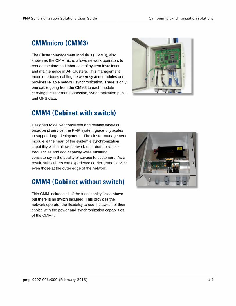
CMMmicro (CMM3)
The Cluster Management Module 3 (CMM3), also
known as the CMMmicro, allows network operators to
reduce the time and labor cost of system installation
and maintenance in AP Clusters. This management
module reduces cabling between system modules and
provides reliable network synchronization. There is only
one cable going from the CMM3 to each module
carrying the Ethernet connection, synchronization pulse
and GPS data.
CMM4 (Cabinet with switch)
Designed to deliver consistent and reliable wireless
broadband service, the PMP system gracefully scales
to support large deployments. The cluster management
module is the heart of the system’s synchronization
capability which allows network operators to re-use
frequencies and add capacity while ensuring
consistency in the quality of service to customers. As a
result, subscribers can experience carrier-grade service
even those at the outer edge of the network.
CMM4 (Cabinet without switch)
This CMM includes all of the functionality listed above
but there is no switch included. This provides the
network operator the flexibility to use the switch of their
choice with the power and synchronization capabilities
of the CMM4.
PMP Synchronization Solutions User Guide
pmp-0297 006v000 (February 2016) 2-1
Chapter 2: Cambium Cluster Management Module
(CMM)
The CMM4 consists of 3 subsystems, described in the following sections:
The CMM4 enclosure and controller board
Power supply(s)
An EtherWAN switch (contained only in 1090CKHH models - mounted in the CMM4)

PMP Synchronization Solutions User Guide CMM4 and Controller Board
pmp-0297 006v000 (February 2016) 2-2
CMM4 and Controller Board
The Cluster Management Module 4 (CMM4) provides power, sync, and network connectivity for up to
eight APs, backhauls, and Ethernet terrestrial feeds in a variety of configurations. The CMM4 provides
Sync over Power over Ethernet and integrated surge suppression on the controller board for up to 8
APs or BHs. Both a custom 30 VDC power scheme and a custom 56 VDC power scheme are
available. Neither is the same as the later IEEE Standard 802.3af, and neither is compatible with it.
Managed switching using a hardened EtherWAN switch (1090CKHH models). The CMM4 ships with
a 14-port EtherWAN switch and is also available without a switch. The CMM4 originally shipped with
a 9-port EtherWAN switch.
A weather-tight enclosure with either 4 or 7 glands/ports for Ethernet and power cables (1090 and
1091 models).
Surge suppression on the controller board for the incoming 30V DC and 54V DC power lines and
GPS coax cable.
Auto-negotiation on the Ethernet ports. Ports will auto-negotiate to match inputs that are either
100Base-T or 10Base-T, and either full duplex or half duplex, when the connected device is set to
auto-negotiate. Alternatively, these parameters are settable.
An always-on NTP (Network Time Protocol) server that can provide date and time to any radio that
can reach the CMM’s management IP address.
Table 1 shows model numbers and Ethernet switch configurations.
Table 1 CMM4 model numbers and Ethernet switch configurations
CMM4
Model No.
CMM4
Extended
Model
No.
EtherWAN Switch
Cable
glands
(ports) Total
Ports
10/100
Base-
TX
Ports
10/100/1000
Base-TX
Ports
1090CK
1090CKHH
(current
units)
14 12 2 7
1090CKAA
(earlier
units)
9 8 1 4
1091HH – No Switch 7
1092HH
(Rackmount) – No Switch –

PMP Synchronization Solutions User Guide CMM4 and Controller Board
pmp-0297 006v000 (February 2016) 2-3
Inside the CMM4 enclosure is a controller board, an EtherWAN switch (model 1090CKHH only), and a
GPS coax surge suppressor.
The controller board injects power and synchronization on up to eight Ethernet ports and provides the
equivalent of 600SS surge suppression on each of the eight ports. The controller board is managed
using a web browser, Telnet, or SNMP, and is supported by the Prizm Element Management System
(EMS). The controller board receives 30 VDC power and/or 54 VDC from external power supplies, and
provides 20 VDC power for the EtherWAN switch and other auxiliary equipment. The controller board
includes a GPS module, which provides sync and GPS information to the CMM, a management port, an
override toggle switch, and an auxiliary sync port for connecting to another CMM.
IMPORTANT! The controller board does not convert 30 VDC to 56 VDC or 56 VDC to 30 VDC. To power 56 VDC equipment from a CMM4 you must provide a 54 VDC power supply, and to power 30 VDC equipment from a CMM4 you must provide a 30 VDC power supply.
The hardened, managed EtherWAN switch (model 1090CKHHonly) provides a full array of networking
features. For details on the EtherWAN switch, see page 2-24.
Figure 3 CMM4 internal view, including cable glands
Weatherized enclosure
N-type coax connector for GPS antenna
EtherWAN 14-port hardened managed switch
Gigabit Ethernet ports
8 Ethernet ports supporting Sync over Power over Ethernet and providing surge suppression
Cable Glands
Patch cables between EtherWAN switch and controller board
Controller board
Patch cable between controller board management port and EtherWAN Switch

PMP Synchronization Solutions User Guide CMM4 and Controller Board
pmp-0297 006v000 (February 2016) 2-4
Figure 4 Rackmount CMM4
Outside the enclosure the CMM4 requires a GPS antenna and a power supply.
The GPS antenna requires a good view of the sky, and should not be mounted at the highest point of the
tower. For best satellite tracking results a clear vew of the southern horizon is required. It is included
with the CMM4 and is also available as a replacement item using part number GPSANTPNM03D.
EtherWAN Switch
Patch cables between EtherWAN switch and controller board
8 Ethernet ports supporting Sync over Power over Ethernet and providing surge suppression
Two 29/30 VDC input terminal blocks
Auxiliary sync port
Controller board management port
Two 56 VDC input terminal blocks
Two 20 VDC output terminal blocks
GPS coax surge suppressor
Override (default) toggle switch
8 Ethernet ports supporting Sync and Power over Ethernet and providing surge suppression Auxiliary sync port
Controller board management port
8 Ethernet ports
Override (default) toggle switch

PMP Synchronization Solutions User Guide CMM4 and Controller Board
pmp-0297 006v000 (February 2016) 2-5
Figure 5 GPS Antenna
The model 1090CKHHand model 1091HH CMM4 as shipped includes:
Weatherized enclosure containing the controller board, EtherWAN Ethernet Switch, and GPS coax
surge suppressor. See page 2-7 for details on EtherWAN switch options.
Patch cables between the controller board and the EtherWAN Ethernet Switch
U-bolts and V-brackets for pole-mounting the CMM4
GPS Antenna
GPS antenna pole-mount kit
A 1-hole cable gland insert for use on the DC power cable
The model 1092HH Rackmount CMM4 as shipped includes:
Rackmounting accessories
GPS Antenna and pole mount accessories
The CMM4 (all models) as shipped does not include:
Any power supply. The appropriate power supply(s), 30 VDC and/or 54 VDC, must be ordered
separately.
Ethernet cables to connect the CMM4 to APs, backhauls, or terrestrial feeds
Coax cable connecting the CMM4 to the GPS antenna

PMP Synchronization Solutions User Guide Power
pmp-0297 006v000 (February 2016) 2-6
Power
The power supply or supplies, 30 VDC and/or 54 VDC, are ordered separately. See Table 2 for pictures
of the 30 VDC and 54 VDC supplies and for power supply part numbers.
The 30 VDC power supply N000000L055A and the 54 VDC power supply
N000000L054A are equipped with a screw terminal and come with no
cables.
Table 2 Power supply part numbers
Name Part Number
30 VDC Power Supply
(no cables or cords) N000000L055A
54 VDC shown, 30 VDC
model features same design 54 VDC Power Supply
(no cables or cords)
N000000L054A
NOTE
The 30 VDC power supply N000000L055A is now included with CMMmicros (Cluster Management
Module micro). Previously, CMMmicros shipped with a 24-Volt DC power supply, but all 24 VDC
modules and radios are compatible with a 30 Volt system. Note that a 54 VDC CMM power supply will
not properly power on 24 VDC radio modules.

PMP Synchronization Solutions User Guide Ethernet Switch
pmp-0297 006v000 (February 2016) 2-7
Ethernet Switch
The model 1090CKHH CMM4 is available with a hardened, full-featured Ethernet switch made by
EtherWAN Systems mounted inside the CMM4 enclosure. The CMM4 ships with a 14-port EtherWAN
switch. Earlier units shipped with a 9-port EtherWAN switch.
For details on the EtherWAN switch, including the download site for its separate manual, see page 2-24.
Currently CMM4s ship as model number 1090CKHH and include a 14-port EtherWAN switch. Twelve
ports support 10/100Base-T Ethernet and two ports supports 1000Base-T (Gigabit) Ethernet. Typically,
eight ports are connected to the eight ports on the controller board via eight Ethernet patch cables, one
port is connected to the management port of the controller board, and the remaining ports are available
for connecting to high speed backhauls, terrestrial feeds, or for local access.
Earlier CMM4s shipped as model number 1090CKHH and included a 9-port EtherWAN switch. Eight
ports support 10/100Base-T Ethernet and one port supports 1000Base-T (Gigabit) Ethernet. Typically,
eight ports are connected to the eight ports on the controller board via eight Ethernet patch cables, and
the Gigabit Ethernet port is connected to the management port of the controller board if the port isn’t
needed for Gigabit Ethernet.
Regardless of CMM4 option chosen, one of the ports on the switch must be cabled to the management
port of the controller board or other access to the controller must be provided. The eight Ethernet lines
pass through the controller board and have power and sync injected, but do not themselves provide
network access to management of the controller board.
CMM4 models 1091HH and 1092HH do not contain an EtherWAN switch, and operators may supply an
external switch for Ethernet traffic management (such as switch-based VLAN, MAC-based trunking, port
security, port mirroring, QoS, etc.)

PMP Synchronization Solutions User Guide Specifications
pmp-0297 006v000 (February 2016) 2-8
Specifications
Table 3 CMM4 specifications
Specification System Range
Max length from CMM to any radio 328 cable feet (100 meters)
Max length from CMM to GPS
antenna 100 cable feet (30.5 meters)
Max length from CMM to another
CMM, if GPS sync cable is used 100 cable feet (30.5 meters)
Dimensions 20.75” x 14.75” x 7.75”
(52.7 cm x 37.5 cm x 19.7)
Weight 14.0 lbs. (6.4 kg)
Operation Temperature -40°F to +131°F (-40°C to +55°C)
Humidity 100% condensing
Ethernet, GPS Sync, and GPS
Coax Cables
The use of cables that conform to the operational
temperature of the product as well as being UV light
protected is mandatory. Shielded Ethernet cables are
strongly recommended
Input Power 29 VDC or 56 VDC, max 10.6A (-40°C)

PMP Synchronization Solutions User Guide Specifications
pmp-0297 006v000 (February 2016) 2-9
Table 4 Rackmount CMM4 specifications
Specification System Range
Max length from CMM to any radio 328 cable feet (100 meters)
Max length from CMM to GPS
antenna 100 cable feet (30.5 meters)
Max length from CMM to another
CMM, if GPS sync cable is used 100 cable feet (30.5 meters)
Dimensions 19” x 9.5” x 1.75” or 1 Rack Space
(48.25 cm x 24 cm x 4.5 cm)
Weight 6.8 lbs. (3 kg)
Ethernet, GPS Sync, and GPS
Coax Cables
The use of cables that conform to the operational
temperature of the product as well as being UV light
protected is mandatory. Shielded Ethernet cables are
strongly recommended
Input Power 29 VDC or 56 VDC, max 10.6A (-40°C)

PMP Synchronization Solutions User Guide Providing sync to CMM via UGPS Module
pmp-0297 006v000 (February 2016) 2-10
Providing sync to CMM via UGPS Module
A UGPS module may also be used as a GPS synchronization source (or backup GPS synchronization
source) for the CMM4 units. The UGPS provides GPS synchronization to the CMM unit via the CMM’s
Aux Sync port (location data is not provided by the UGPS module). This allows any access points or
backhaul masters connected to the CMM to receive sync. This configuration requires that the CMM4 be
configured to “Slave” mode via the CMM GUI. When using the UGPS as a synchronization source for a
CMM4, a special sync cable must be used. This cable may be constructed from an RJ-11 cable using the
pin configuration in Figure 51.

PMP Synchronization Solutions User Guide CMM Planning
pmp-0297 006v000 (February 2016) 2-11
CMM Planning
The following sections discuss Ethernet cabling, power, syncing two co-located CMMs together, and
engineering and ordering cables.
Typical Ethernet Cabling
Physical connectivity and cabling of the CMM4 is variable and is done per the specific requirements of a
given installation. The following sections depict several variations for specific network configurations.
Based on these typical layouts, operators should design connectivity and cabling that best meets their
site-specific needs.
NOTE
CMM4 models 1091HH and 1092HH do not contain an EtherWAN switch, and operators may supply an
external switch for Ethernet traffic management (such as switch-based VLAN, MAC-based trunking,
port security, port mirroring, QoS, etc.). This external switch may be cabled similar to the EtherWAN
switch in the diagrams below.
Standard Ethernet Cabling Configuration
Figure 6 and Figure 7 show the CMM4’s internal ports connected in a standard cabling configuration. In
this configuration there are four Ethernet connections to radios and one connection to a terrestrial feed.
The four Ethernet ports that are powered (indicated by a red light for 29V or a green light for 56V) were
configured using the CMM4 configuration web page. The Ethernet connection to the terrestrial feed is
not powered (no red or green light). An Ethernet cable connects the controller board management port
to the EtherWAN switch. Four of the eight Ethernet ports to radios are shown as unpowered and unused
in this configuration. Local access during local maintenance could be gained by connecting an Ethernet
cable from a local computer to any of the unpowered ports or to an unused port on the EtherWAN switch.

PMP Synchronization Solutions User Guide CMM Planning
pmp-0297 006v000 (February 2016) 2-12
Figure 6 CMM4 Standard Configuration
Figure 7 Rackmount CMM4 Standard Configuration
CAUTION! Do not mis-cable in such a way as to put power on the controller board Management Port.
NOTE
The 30 VDC CMM4 power supply is labeled as 30 VDC and typically measures 30 VDC at its output.
The associated CMM4 terminal blocks are marked 29 VDC, and some associated SM power supplies
are labeled 29.5 VDC. All of these components are elements of a nominal 30 VDC system, and can be
considered “30 VDC” elements.
The 54 VDC CMM4 power supply is labeled as 54 VDC and typically measures 54 VDC at its output.
The associated CMM4 terminal blocks are marked 56 VDC, and associated SM power supplies are
labeled 56 VDC. All of these components are elements of a nominal 56 VDC system, and can be
considered “56 VDC” elements.

PMP Synchronization Solutions User Guide CMM Planning
pmp-0297 006v000 (February 2016) 2-13
NOTE
When powering PMP 450i AP, ePMP 1000 Connectorized with GPS Sync, or Force 110 PTP devices
with a 56 V powered CMM, a crossover cable must be used, or Cambium dongle N000045L001A may
also be used (these devices require pins 8,7 +Vcc and pins 4, 5 DC return).
Configured for 1000Base-T (Gigabit) Ethernet Terrestrial Feed
IMPORTANT! The surge suppression provided by the controller board does not efficiently pass 1000Base-T (Gigabit) Ethernet. Connections required to support Gigabit Ethernet should not pass through the controller board portion of the CMM4 and should have separate surge suppression.
Figure 8 shows typical cabling for supporting a Gigabit Ethernet feed. A Gigabit port of the EtherWAN
switch is used for a terrestrial Gigabit Ethernet feed. The surge suppression on the controller board does
not efficiently pass 1000Base-T (Gigabit) Ethernet, so the Gigabit Ethernet from the EtherWAN switch
needs to
Be cabled so as not to go through the controller board
Have surge suppression provided using a HyperLink Technologies AL-CAT6HPJW surge suppressor
available from L-Com (http://www.l-com.com) or equivalent.
The AL-CAT6HPJW surge suppressor can be either mounted
inside the CMM4 enclosure (using stick-and-rip tape like Velcro or other secure mounting), with the
ground lug on the surge suppressor connected to the ground lug on the inside of the enclosure with
10 AWG (6 mm2) green ground wire.
outside the CMM4 enclosure, with the ground lug on the surge suppressor connected to known-good
ground/protective earth with 10 AWG (6 mm2) green ground wire.
in the case where the CMM4 is located in a telecommunication hut, mounted outside the hut at the
point of cable penetration, with the ground lug on the surge suppressor connected to known-good
ground/protective earth with 10 AWG (6 mm2) green ground wire.

PMP Synchronization Solutions User Guide CMM Planning
pmp-0297 006v000 (February 2016) 2-14
Figure 8 CMM4 cabled to use Gigabit Ethernet feed
Configured for Cambium PTP 400, 500, and 600 Series Ethernet Bridges
PTP 400, 500, and 600 Series Ethernet bridges can use the CMM4’s EtherWAN switch for their network
connectivity.
These units use a different powering scheme and must be powered using their external PIDU (Powered
InDoor Unit), not the powering option of the controller board in the CMM4. The PIDU must be located
between the CMM4 and the ODU (OutDoor Unit – the radio), so as not to put power on ports of the
EtherWAN switch.
IMPORTANT! The surge suppression provided by the controller board does not efficiently pass 1000BaseT (Gigabit) Ethernet. Connections required to support Gigabit Ethernet should not pass through the controller board portion of the CMM4 and should have separate surge suppression.
PTP 500 and PTP 600 Series bridges operate at greater than 100 Mbit speeds and so should not be
cabled to the controller board portion of the CMM4. Surge suppression to protect the EtherWAN switch
should be provided by a Hyperlink Technologies AL-CAT6HP-JW surge suppressor, cabled as shown in
Figure 9. The surge suppressor should be mounted
within 3 ft (1 m) of the CMM4 if the CMM4 is located outdoors
on the outside of the building or communications hut at the point of cable penetration if the CMM4 is
located indoors.

PMP Synchronization Solutions User Guide CMM Planning
pmp-0297 006v000 (February 2016) 2-15
Figure 9 CMM4 cabled to support PTP 500/600
PTP 400 Series bridges operate at less than 100 Mbit speeds and so can be cabled to one of the eight
Ethernet ports on the controller board, thus taking advantage of the controller board for surge
suppression. The port must be configured to be unpowered. The PTP 400 Series bridge is powered by
its own externally located PIDU.
NOTE
PTP 450 devices do not support synchronization over power port.

PMP Synchronization Solutions User Guide CMM Planning
pmp-0297 006v000 (February 2016) 2-16
Power Planning
IMPORTANT! The power supply or supplies for the CMM4 must be separately ordered – no power supplies are included under model numbers 1090CK, 1091, or 1092. (This differs from the CMMmicro where the power supply is included when model number 1070CK is ordered.) See Table 2 for pictures of the 30 VDC and 54 VDC supplies and for power supply part numbers.
A 30 VDC power supply is needed for the following equipment:
PMP 100 FSK regular and Advantage APs
PMP 54400 OFDM APs
PTP 100 FSK BHs
PTP 54200 OFDM BHs
PMP 450 Series OFDM APs
ePMP Series
A 54 VDC power supply is needed for the following equipment:
PMP 320 802.16e APs
PMP 430 OFDM APs
PMP 49400 OFDM APs
PTP 49200 OFDM BHs
PMP 450i OFDM APs (requires crossover cable N000045L001A for Ethernet
connection)
NOTE: In most cases SMs use the same voltage as their associated APs. Three exceptions to be aware of are
◦ PMP 320 SMs use 802.3af power supplies
◦ PMP 430 SMs use 30 VDC power supplies.
◦ PMP 450 900 MHz SMs use 30 VDC power supplies
There are four input power terminal blocks inside the CMM4. Two of them are for 29/30 VDC input, and
the other two are for 56 VDC input. The two 29 VDC terminal blocks and the two 56 VDC terminal blocks
allow the CMM4 to be powered from redundant power supplies, if so desired.
PMP Synchronization Solutions User Guide CMM Planning
pmp-0297 006v000 (February 2016) 2-17
The 30 VDC CMM4 power supply is labeled as 30 VDC and typically measures 30 VDC at its output. The
associated CMM4 terminal blocks are marked 29 VDC, and some associated SM power supplies are
labeled 29.5 VDC. All of these components are elements of a nominal 30 VDC system, and can be
considered “30 VDC” elements.
The 54 VDC CMM4 power supply is labeled as 54 VDC and typically measures 54 VDC at its output. The
associated CMM4 terminal blocks are marked 56 VDC, and associated SM power supplies are labeled
56 VDC. All of these components are elements of a nominal 56 VDC system, and can be considered “56
VDC” elements.
One of the CMM 56 VDC blocks has 2 terminals while the other has 3. The third terminal provides an
additional grounding point, if needed.
If you are using a CMM4 to power both 30 VDC and 56 VDC systems, then you must install both 30 VDC
and 54 VDC power supplies along with the CMM4. These power supplies must be wired to the correct
terminal blocks (marked 29 VDC and 56 VDC).
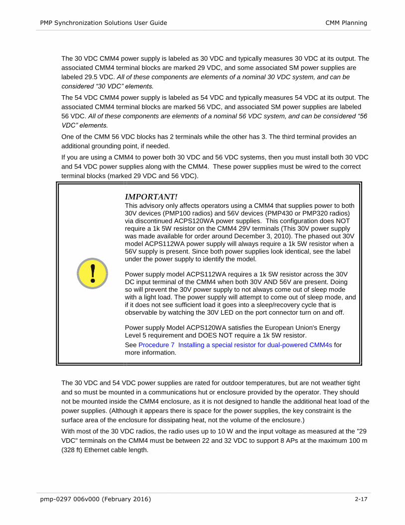
IMPORTANT! This advisory only affects operators using a CMM4 that supplies power to both 30V devices (PMP100 radios) and 56V devices (PMP430 or PMP320 radios) via discontinued ACPS120WA power supplies. This configuration does NOT require a 1k 5W resistor on the CMM4 29V terminals (This 30V power supply was made available for order around December 3, 2010). The phased out 30V model ACPS112WA power supply will always require a 1k 5W resistor when a 56V supply is present. Since both power supplies look identical, see the label under the power supply to identify the model. Power supply model ACPS112WA requires a 1k 5W resistor across the 30V DC input terminal of the CMM4 when both 30V AND 56V are present. Doing so will prevent the 30V power supply to not always come out of sleep mode with a light load. The power supply will attempt to come out of sleep mode, and if it does not see sufficient load it goes into a sleep/recovery cycle that is observable by watching the 30V LED on the port connector turn on and off. Power supply Model ACPS120WA satisfies the European Union's Energy Level 5 requirement and DOES NOT require a 1k 5W resistor. See Procedure 7 Installing a special resistor for dual-powered CMM4s for more information.
The 30 VDC and 54 VDC power supplies are rated for outdoor temperatures, but are not weather tight
and so must be mounted in a communications hut or enclosure provided by the operator. They should
not be mounted inside the CMM4 enclosure, as it is not designed to handle the additional heat load of the
power supplies. (Although it appears there is space for the power supplies, the key constraint is the
surface area of the enclosure for dissipating heat, not the volume of the enclosure.)
With most of the 30 VDC radios, the radio uses up to 10 W and the input voltage as measured at the "29
VDC" terminals on the CMM4 must be between 22 and 32 VDC to support 8 APs at the maximum 100 m
(328 ft) Ethernet cable length.

PMP Synchronization Solutions User Guide CMM Planning
pmp-0297 006v000 (February 2016) 2-18
With PMP 54400 APs, the radio uses up to 12 W at 30 VDC and the input voltage as measured at the
"29 VDC" terminals on the CMM4 must be between 28 and 32 VDC to support 8 APs at the maximum
100 m (328 ft) Ethernet cable length.
When supporting 56 VDC systems, the input voltage as measured at the “56 VDC” terminals on the
CMM4 must be between 44 and 59 VDC.
The CMM4 controller board provides two 20 VDC outputs – one for the EtherWAN switch, and one
optionally available for powering another low power device mounted in the enclosure by the operator,
such as a fiber-to-copper media converter. Total 20 VDC accessory power should not exceed 20 W.
In cases where -48 VDC power is available and powering from the -48 VDC is desired (for example, in
some telecommunications huts), procure a -48 VDC to +56 VDC converter such as a Mean Well Model
SD-350C-48 and install between the -48 VDC source and the +56 VDC power supply.
NOTE
EU Countries Only
To enable regulatory compliance with the European Union (EU) directives, a power
line filter module must be installed on the DC side of the power supply. This module
may be ordered from Cambium Networks (part number N000000L056A). Please
reference section EU countries only – power line filter module installation on page 2-
54.
Syncing Two Co-located CMMs Together
Two CMMs can be synced together to meet either of the following goals:
Case 1 – One GPS antenna for two CMMs: Use a single GPS antenna to support two CMMs. This
can be advantageous for a site with 2 CMMs where the site owner is charging per antenna and the
operator wishes to minimize site costs by only installing one GPS antenna.
Case 2 - Redundant Sync: Take advantage of co-located CMMs, each with its own antenna, to
provide “warm spare” redundant sync. If one GPS antenna, coax cable, or GPS module has
problems, remote re-configuration can re-establish sync to that CMM.
The CMMs can be any combination of CMMs - either two CMM4s, two CMMmicros, or a CMM4 and a
CMMmicro.
Syncing two CMMs together requires connecting their RJ-11 auxiliary ports together with a 6-wire cable
and configuring each CMM appropriately. The location of the RJ-11 auxiliary port is shown in Figure 3.
The connection cable is a special cable, not a straight-through cable. See page 2-23 for information on
the cable and Figure 11 for cable pinouts.

PMP Synchronization Solutions User Guide CMM Planning
pmp-0297 006v000 (February 2016) 2-19
Case 1 – Redundant Sync
In this case, each CMM is connected to its own GPS antenna via coax in the standard way, and the two
CMMs are connected via a special cable between the auxiliary sync RJ-11 ports of each CMM. If one
CMM loses sync due to problems with its GPS antenna, coax cable, or GPS module, that CMM can be
re-configured remotely over the network to get sync from the other CMM by going to the Configuration >
CMM web page and setting the sync source to Slave (RJ11 Port).
In normal operation, the appropriate web pages of each CMM will display GPS information, as will the
appropriate pages of connected APs and BHMs. Each CMM can be used as a NTP (Network Timing
Protocol) server for time-of-day information for APs and BHMs, configured at the AP or BHM.
Once reconfigured to get sync over the auxiliary sync RJ-11 Port, a CMM and its connected APs and
BHMs will no longer display GPS information. That CMM will no longer be providing NTP server
functions, and any AP or BHM configured to point to it for time-of-day will need to be re-configured to
point to a different NTP server to get accurate time-of-day information.
Depending on network design and other equipment in the network, the two CMMs may be connected
with an Ethernet cable, or may be each fed separately.
Case 2 – One GPS antenna for two CMMs
A typical scenario for the use of Case 2 would be where a site or building owner is charging per antenna,
the site requires 2 CMMs, and the operator wishes to minimize site costs by only installing one GPS
antenna.
In this case, the GPS antenna connects to one CMM via coax cable, and the two CMMs are connected
via a cable between the auxiliary sync RJ11 ports of each CMM. Sync is passed from one CMM to the
other via this cable. The Sync Source on the Configuration > CMM page of the CMM connected to the
GPS antenna should be set to Master (GPS Module), and the Sync Source on the Configuration >
CMM page of the other CMM should be set to Slave (RJ11 Port).
The slave CMM and its connected APs and BHMs will not display GPS information and the slave CMM
will not function as an NTP (Network Time Protocol) server.
Depending on network design and other equipment in the network, the two CMMs may be connected
with an Ethernet cable, or may be each fed separately.

PMP Synchronization Solutions User Guide CMM Planning
pmp-0297 006v000 (February 2016) 2-20
Cables
Ethernet Cables
The operator provides the Ethernet cables between the CMM4 and the radios it supports. They must be
engineered to length and are not included with the CMM4. The cable length from the CMM4 to any radio
must be under 100 m (328 ft).
Cables are available from Best-Tronics, Inc., http://best-tronics.com/. These cables can be ordered in
lengths up to 328 ft (100 m) and are listed in Table 5.
Table 5 Recommended Ethernet cables
Typical
Use Best-
Tronics
Part #
Description
Infrastructure
Ethernet
cable
BT-0781S-XXX RJ-45 to RJ-45 straight, shielded, UV-resistant Ethernet
cable using outdoor STP Cat 5e cable, lower cost than
plenum-rated, available only in black.
Infrastructure
Ethernet
cable for
plenums
BT-0562S-XXX RJ-45 to RJ-45 straight, shielded, UV-resistant, plenum-
rated Ethernet cable using outdoor STP Cat 5e cable,
available in beige, blue, grey, or white.
IMPORTANT! Shielded Ethernet cable is strongly recommended for AP and BH installations.
Alternatively, equivalent cables may be procured by the operator, fabricated by the operator in a depot,
or fabricated at site. The modules have auto MDX/MDIX and so either straight-through or crossover
Ethernet cables may be used. Pinouts for straight-through cables are shown in Table 6 and Table 7.
Figure 10 shows the location of Pin 1, relative to the lock tab on the connector.
Table 6 RJ-45 pinouts for straight-through Ethernet cable - 30 VDC
Pin 1 white / orange Pin 1
Pin 2 orange Pin 2
Pin 3 white / green Pin 3
Pin 4 blue Pin 4
Pin 5 white / blue Pin 5
Pin 6 green Pin 6
Pin 7 white / brown Pin 7
Pin 8 brown Pin 8 Pins 7 and 8 carry power to the modules.

PMP Synchronization Solutions User Guide CMM Planning
pmp-0297 006v000 (February 2016) 2-21
Table 7 RJ-45 pinouts for straight-through Ethernet cable - 56 VDC
Pin 1 white / orange Pin 1
Pin 2 orange Pin 2
Pin 3 white / green Pin 3
Pin 4 blue Pin 4
Pin 5 white / blue Pin 5
Pin 6 green Pin 6
Pin 7 white / brown Pin 7
Pin 8 brown Pin 8 Pins 5 and 8 carry power to the modules.
Figure 10 Location of pin 1
(Lock tab underneath)
← Pin 1
GPS Antenna Coaxial Cable
The operator provides the GPS antenna coaxial cable between the CMM4 and the GPS antenna. It must
be engineered to length and is not included with the CMM4. In most cases, the cable length from the
CMM4 to the GPS antenna must be under 30 m (~100 ft).
Antenna cables can be ordered from Best-Tronics, Inc., http://best-tronics.com/. Antenna cables can be
ordered in lengths up to 100 ft (30.4 m), as listed in Table 8.
Table 8 Recommended antenna cable
Best-
Tronics
Part # Description
BT-0564 N to N GPS antenna cable
Alternatively, equivalent cables may be procured by the operator, fabricated by the operator in a depot,
or fabricated at site using
Up to 100 feet (30.4 meters) of LMR200 coaxial cable
2 Times Microwave N-male connectors (Times Microwave P/N TC-200-NM) or equivalent connectors
Bulk unterminated Ethernet cable can be ordered
from Best-Tronics as bulk cable:
CA-0287S: (shielded, plenum rated)
CA-0367S: (lower cost, shielded, non-
plenum-rated)

PMP Synchronization Solutions User Guide CMM Planning
pmp-0297 006v000 (February 2016) 2-22
NOTE: The CMM4 has a female N-type coax connector on the outside of the enclosure, whereas the CMMmicro has a female BNC-type connector inside the enclosure. Take this into account when ordering or fabricating cables, and when replacing a CMMmicro with a CMM4.
DC Cables
Cambium recommends the use of flame-retardant, moisture and sunlight-resistant cable rated to 75° C
wet and bendable at -25° C for the DC cable between the power supply(s) and the CMM4. Examples of
such cable include General Cable (http://www.generalcable.com), catalog number 234580 for 12 AWG
cable and catalog number 236300 for 10 AWG cable, found in the Telecommunications Catalog.
Recommended wire size for the CMM4’s DC cable in most systems is shown in Table 9. These wire
sizes support up to 8 radios (30 VDC or 56 VDC radios) at up to 100 m (328 ft) Ethernet cable length
from the CMM4.
Table 9 Wire size for CMM4 DC cable
For supporting 8 PMP 54400 APs or PTP 54200 BHs (which are 12 W 30 VDC radios), reduce either the
maximum DC cable length or the Ethernet cable length by half. For example, if the Ethernet cable length
from CMM4 to 8 PMP 54400 APs is 50 m (164 ft) or less, the DC lengths in Table 9 can be used. If the
Ethernet cable length from CMM4 to 8 PMP 54400 APs is 100 m (328 ft), then halve the lengths shown
in Table 9.
DC Power Cord Length Wire Gauge
Under 12 ft (12.6 m) 14 AWG (2 mm2)
12 - 90 ft (3−25 m) 12 AWG (4 mm2)
91−145 ft (26−45 m) 10 AWG (6 mm2)
146−230 ft (46−70 m) 8 AWG (10 mm2)

PMP Synchronization Solutions User Guide CMM Planning
pmp-0297 006v000 (February 2016) 2-23
CMM Sync and UGPS Sync Cable
As described in on page 2-18, two CMMs (two CMMmicros, two CMM4s, or a CMMmicro and a CMM4)
can be connected together with a CMM sync cable to provide either
The ability to have one GPS antenna support two CMMs
“Warm spare” redundant sync
Pinouts for the CMM sync cable are shown in Figure 11. Figure 12 shows the location of Pin 1, relative
to the lock tab on the connector. When using a UGPS module for providing synchronization pulses to a
CMM4 unit, use the pinout configuration shown in Figure 51.
NOTE: The CMM sync cable used to connect two CMMs for sync purposes has different pinouts than the straight-through sync cable used to connect a “remote AP” to an SM, or an AP or BHM to a CMM2.
Figure 11 CMM sync cable pinout
Figure 12 Location of pin 1
(Lock tab is on other side)
<- Pin 1

PMP Synchronization Solutions User Guide EtherWAN Switch Information
pmp-0297 006v000 (February 2016) 2-24
EtherWAN Switch Information
This section includes key information on the EtherWAN switch. For full details and configuration
information, EtherWAN switch manuals are downloadable from http://www.etherwan.com/support-
mo.php. Consult Table 10 to obtain the appropriate model number for your EtherWAN switch to use to
download the correct manual.
EtherWAN switch management may be accessed in one of three ways:
Standard web-based browser interface
External SNMP-based network management using SNMP commands or an Element Management
System such as Prizm or One Point Wireless Manager
Administration console via the switch’s RS-232 serial port using Windows Hyperterminal or
equivalent
The EtherWAN switch as provided has the IP address, login ID, and password as shown in Table 10.
Table 10 EtherWAN switch details
CMM4
Extended
Model
No.
EtherWAN Switch
Default IP
address Login ID Default
password Total
Ports
10/100
Base-
TX
Ports
10/100/1000
Base-TX
Ports
EtherWAN
Model No.
1090CKHH 14 12 2 EX72129A 169.254.1.1
root
(not
changeable
by user)
No
password
1090CKAA
(earlier
versions) 9 8 1 EX96000 192.168.1.10
admin
(not
changeable
by user)
No
password
The 14-port EtherWAN switch may be reset (rebooted) either remotely or after gaining physical access to
the CMM4:
remotely: access the CMM4 controller board web page, navigate to Configuration > CMM and
click the Reset OEM Switch button to power cycle the switch.
after gaining physical access to the inside of the CMM4 enclosure: press the inset Reset button on
the EtherWAN switch’s faceplate using a nail or similar tool.
Either process reboots the switch but does not reset it to factory defaults.
The 9-port EtherWAN switch may be reset (rebooted) remotely by accessing the CMM4 controller board
web page, navigating to Configuration > CMM and clicking the Reset OEM Switch button. This button
power cycles the EtherWAN switch but does not reset it to factory defaults.

PMP Synchronization Solutions User Guide EtherWAN Switch Information
pmp-0297 006v000 (February 2016) 2-25
If you lose or forget the IP address of the EtherWAN switch after configuring it to an address other than
the default IP address, gain physical access to the CMM4, access the EtherWAN switch via its RS-232
serial port (which doesn’t require an IP address), and proceed to view or set the IP address. Alternatively,
you may wish to use Wireshark, Angry IP Scanner, or other tools to discover the missing IP address.
If after configuring a password you lose or forget it, contact Technical Support for assistance, using the
contact information on page ix.

PMP Synchronization Solutions User Guide Configuring a CMM4
pmp-0297 006v000 (February 2016) 2-26
Configuring a CMM4
Web pages on the CMM4 provide status information and support configuration. The eight Ethernet ports
can be configured, and information is provided on GPS status, Port configuration, FPGA and software
revision.
For information on configuring the EtherWAN switch, see the EtherWAN Switch Manual. The manual is
available for download as described in on page 2-24.
Configuring IP Communications Parameters
An example of the CMM4 IP tab is displayed in Figure 13.
Figure 13 IP tab of CMM4
The IP tab allows you to set the IP communications parameters for management of the CMM4.
Table 11 IP tab attributes
Attribute Meaning
IP Address
This is the IP address of the CMM4 controller board. The EtherWAN Switch has a
separate and distinct IP address that is set using the EtherWAN Switch web or serial
interface.
The default value for this parameter is 169.254.1.1.
Subnet Mask
This is the subnet mask of the CMM4 (controller board). The EtherWAN Switch has
a separate subnet mask that is set using the Ethernet Switch web or serial interface.
The default value for this parameter is 255.255.255.0.
PMP Synchronization Solutions User Guide Configuring a CMM4
pmp-0297 006v000 (February 2016) 2-27
Attribute Meaning
Default Gateway
This is the default gateway of the CMM4 (controller board). The EtherWAN Switch
has a separate default gateway setting that is set using the Ethernet Switch web or
serial interface.
The default for this parameter is 169.254.0.0.
Since both the controller board and the 14-port EtherWAN switch have the same
default IP address, either may respond when using IP address 169.254.1.1 from
your PC. You can configure first whichever unit responds first, as easily determined
by the distinctive web pages of the controller board or the EtherWAN switch, or you
can use Procedure 1 to more deterministically access and configure the EtherWAN
switch’s and controller board’s IP addresses.
Procedure 1 Configuring EtherWAN switch and Controller Board IP Addresses
1 Connect an Ethernet cable between your PC and the EtherWAN switch.
2 Disconnect the patch cable between the controller board management port and the
EtherWAN switch.
3 Enter the EtherWAN switch’s web pages using your browser and IP address 169.254.1.1
and proceed to configure the EtherWAN switch.
4 Reconnect the patch cable between the controller board management port and the
EtherWAN switch.
5 Enter the controller board’s web pages using your browser and IP address 169.254.1.1
and proceed to configure the CMM4 controller board.
6 Disconnect your PC from the EtherWAN switch.
Overriding Forgotten IP Addresses, Usernames, or Passwords
By using the toggle switch on the CMM4 controller board, you can temporarily override a lost or unknown
IP address, username, or password as follows:
When the toggle switch is in the “Default” position (up or towards the operator), a power cycle causes
the CMM4 to boot with the default IP address and no username or password required. The CMM
GUI displays a message indicating that the unit has been powered up in default mode.
When the toggle switch is in the “Normal” position (down or away from the operator) a power cycle
causes the CMM4 to boot with your operator-set IP address, username(s) and password(s).

PMP Synchronization Solutions User Guide Configuring a CMM4
pmp-0297 006v000 (February 2016) 2-28
To override a lost or unknown IP address or password, perform the following steps.
Procedure 2 Overriding forgotten IP addresses, usernames, or passwords
IMPORTANT!
When rebooted into override mode the ports on the CMM4 are temporarily unpowered. APs or BHs connected to the CMM4 will not have power, so you will temporarily lose the ability to access the CMM4 through those APs or BHs.
1 Gain physical access to the inside of the CMM4 enclosure.
2 Establish direct Ethernet connectivity to the CMM4 (not through an AP or BH).
3 Flip the toggle switch to the “Default” position (normally up, toward you).
4 Power cycle the CMM4.
RESULT: The module can now be accessed with the default IP address of 169.254.1.1, no
username, and no password. Ports are not currently powered due to toggle switch
override and are shown unpowered on the Configuration > Ports tab.
5 View the current IP address or set a new IP address on the Configuration > IP tab, view
users on the Account > Change Users Password tab, add users on the Account >
Add User tab, or set a new password on the Account > Change Users Password tab.
6 Change any other configuration values if desired. If you change ANY parameters on the
Configuration > Ports tab then the displayed parameters (including any unpowered
ports) will be used when rebooted with the toggle switch in the “Normal” position. Leave
ALL unchanged and the previous port configuration will be used.
IMPORTANT! If you leave the parameters on the Configuration > Ports tab unchanged, the ports will return to the state they were in before the override. Those that were powered before will be powered again. However, if you click “Save Changes” on the Configuration > Ports page before rebooting then the next boot will come up with the displayed port configuration.
7 Click the Save Changes button.
8 Flip the toggle switch to the “Normal” position (nominally down, away from you).
9 Click the Reboot button.

PMP Synchronization Solutions User Guide Configuring a CMM4
pmp-0297 006v000 (February 2016) 2-29
RECOMMENDATION: Note or print the IP settings from the Configuration > IP tab. Ensure that you can readily associate these IP settings with the module for future use.
NOTE: An override/default plug (an RJ-11 connector with pins 4 and 6 tied together) inserted into the auxiliary port before booting the CMM4 is equivalent to using the toggle switch and will also temporarily override a lost or unknown IP address, username, or password.
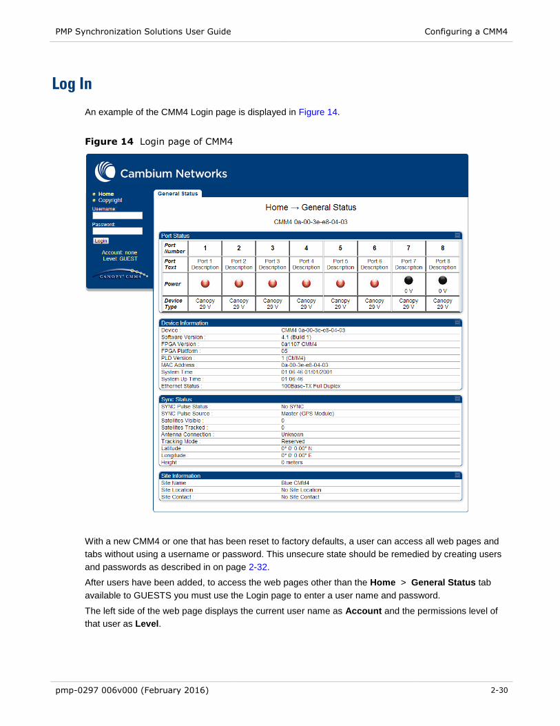
PMP Synchronization Solutions User Guide Configuring a CMM4
pmp-0297 006v000 (February 2016) 2-30
Log In
An example of the CMM4 Login page is displayed in Figure 14.
Figure 14 Login page of CMM4
With a new CMM4 or one that has been reset to factory defaults, a user can access all web pages and
tabs without using a username or password. This unsecure state should be remedied by creating users
and passwords as described in on page 2-32.
After users have been added, to access the web pages other than the Home > General Status tab
available to GUESTS you must use the Login page to enter a user name and password.
The left side of the web page displays the current user name as Account and the permissions level of
that user as Level.

PMP Synchronization Solutions User Guide Configuring a CMM4
pmp-0297 006v000 (February 2016) 2-31
NOTE
All CMM user accounts are local to the device.
User Update
An example of the CMM4 User Update tab is displayed in Figure 15..
Figure 15 Changer Users Password tab of CMM4
The Change Users Password tab provides the following options:
Table 12 Change User Password tab attributes
Attribute Meaning
New Password Type the new password (up to 32 alphanumeric characters) that you want to
use for management access to this CMM4.
Confirm Password Retype what you typed into the New Password parameter. If the password
differs from the password you typed into the New Password field a failure
message will be displayed in the Account Status field.
Change Password To put the new password for the user into immediate effect, click this button.
Account Status This is a read-only field that provides information on the current activity for that
screen. For instance, if changing the password was successful a message will
be displayed indicating the new password is active.

PMP Synchronization Solutions User Guide Configuring a CMM4
pmp-0297 006v000 (February 2016) 2-32
Add User
An example of the CMM4 Add User tab is displayed in Figure 16.
Figure 16 Add User tab of CMM4
If you are of ADMINISTRATOR level, the Add User Tab provides the following options to you.
Table 13 Add User attributes
Attribute Meaning
User Name Type the user name that you want to assign to the user you are adding.
Level Use the down arrow to select the desired permission level for the user you are
adding. Choices include INSTALLER and ADMINISTRATOR with the difference
being that a user with INSTALLER permissions can only change their own
password and cannot add or delete users, whereas a user with ADMINISTRATOR
permissions can change any user’s password and can add and delete users.
New Password Type the new password (up to 32 alphanumeric characters) for management
access to this CMM4 by the user you are adding. Leaving this field blank means no
password is needed and any password (or no password) will allow the user to log
in.
Confirm
Password
Retype what you typed into the New Password parameter. If there is a failure the
“Account Status” will indicate that the new password failed.
Account Status This is a read-only field that provides information on the current activity for that
screen. For instance, if adding a new user was successful a message will be
displayed indicating the user has been added.

PMP Synchronization Solutions User Guide Configuring a CMM4
pmp-0297 006v000 (February 2016) 2-33
Delete User
An example of the CMM4 Delete User tab is displayed in Figure 17.
Figure 17 Delete User tab of CMM4
If you are of ADMINISTRATOR level and want to remove a user, the Delete Users Password tab allows
you to do so as follows:
Table 14 Delete User attributes
Attribute Meaning
User Use the down arrow to select the user you want to remove. Note that the username used to log into the radio may not be deleted
Delete Ensure that the intended user is selected. Then click this button.
Account Status This is a read-only field that provides information on the current activity for that screen. For instance, if deleting the user was successful a message will be displayed indicating the user has been deleted.
Configuring the CMM4 ports
An example of the CMM4 Port Configurations tab is displayed in Figure 18.
Figure 18 Port Configuration tab of CMM4

PMP Synchronization Solutions User Guide Configuring a CMM4
pmp-0297 006v000 (February 2016) 2-34
The Port Configurations tab provides the following parameters.
Table 15 Port Configuration attributes
Attribute Meaning
Port 1 to 8: Description This is a user-defined field that identifies the port. It
appears in the Home -> General Status page.
Port 1 to 8: Power On or Off Select Power On to restore power over Ethernet to the
device that is connected to this port or Power Off to
remove power from it.
Ports 1 to 8: Power Cycle A button to invoke this feature is visible only when the port
is powered up.
Ports 1 to 8: Device Type Select 29 V or 56 V to identify the type of power supplied
to that port. The red light indicates 29 V and the green
light indicates 56V on the port status bar.
Configuring General CMM4 Parameters
An example of the CMM4 Configuration tab is displayed in Figure 19.
Figure 19 CMM4 Configuration tab

PMP Synchronization Solutions User Guide Configuring a CMM4
pmp-0297 006v000 (February 2016) 2-35
The CMM4 Configuration tab provides the following parameters.
Table 16 CMM tab attributes
Attribute Meaning
Session Timeout Enter the expiry in seconds for remote management sessions via HTTP, telnet, or ftp access to the CMM4 up to a maximum of 2592000 seconds.
Webpage Auto Update Enter the frequency (in seconds) for the web browser to automatically refresh the web-based interface. The default setting is 0. The 0 setting causes the web-based interface to never be automatically refreshed.
Ethernet Switch Power If you change this value and then click Save Changes, the change becomes effective immediately and the previous value is lost.
Sync Source Specify how the CMM4 should receive timing, either
◦ Master (GPS Module)
◦ Slave (RJ11 Port)
For additional information on using the Slave sync source, page 2-18.
Verify GPS Message
Checksum
When enabled, the device validates GPS messaging to ensure that the
radio is properly receiving data from the GPS source. If a GPS source is
not calculating and sending checksum data properly, the AP will still receive
synchronization pulses but not GPS data (location, data, etc.) and the
Invalid Message counter will increase on the radio’s Home > GPS Status
page. If an AP is receiving synchronization properly from a GPS unit but is
not receiving GPS data, operators may set Verify GPS Message
Checksum to “Disabled” to ignore checksum failures and to allow the AP to
process the GPS data.
Link Speeds If you wish to force the CMM4 to a speed or duplex state, or to return the module to auto-negotiating speed and duplex state, change the selection for the port. The range of selections is defined below:
Table 17 Link Speed selections for CMM4
Selection Result
Auto Negotiation
The CMM4 attempts to auto-negotiate speed and duplex state.
(This is the default and recommended setting for most network configurations.)
10Base T Half Duplex
The CMM4 is forced to 10 Mbps and half duplex.
10Base T Full Duplex
The CMM4 is forced to 10 Mbps and full duplex.
100Base T Half Duplex
The CMM4 is forced to 100 Mbps and half duplex.
100Base T Full Duplex
The CMM4 is forced to 100 Mbps and full duplex.
If you change this value for a port and then click Save Changes, the change becomes effective immediately and the previous value is lost.
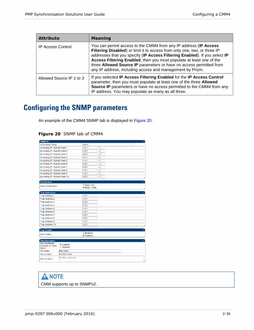
PMP Synchronization Solutions User Guide Configuring a CMM4
pmp-0297 006v000 (February 2016) 2-36
Attribute Meaning
IP Access Control You can permit access to the CMM4 from any IP address (IP Access Filtering Disabled) or limit it to access from only one, two, or three IP addresses that you specify (IP Access Filtering Enabled). If you select IP Access Filtering Enabled, then you must populate at least one of the three Allowed Source IP parameters or have no access permitted from any IP address, including access and management by Prizm.
Allowed Source IP 1 to 3 If you selected IP Access Filtering Enabled for the IP Access Control parameter, then you must populate at least one of the three Allowed Source IP parameters or have no access permitted to the CMM4 from any IP address. You may populate as many as all three.
Configuring the SNMP parameters
An example of the CMM4 SNMP tab is displayed in Figure 20.
Figure 20 SNMP tab of CMM4
NOTE
CMM supports up to SNMPv2.

PMP Synchronization Solutions User Guide Configuring a CMM4
pmp-0297 006v000 (February 2016) 2-37
The SNMP tab provides the following parameters.
Table 18 SNMP tab attributes
Attribute Meaning
Community String
Specify a control string that allows Prizm or a Element Management System
(EMS) to access the CMM4 via SNMP. No spaces are allowed in this string.
The default string is Canopy. The value is clear text and is readable by a
packet monitor. You can attain additional security by configuring the Accessing
Subnet and Read Permissions parameters.
Accessing Subnet
Specify the addresses that are allowed to send SNMP requests to this CMM4.
The EMS must have an address that is among these addresses (this subnet).
You must enter both
The network IP address in the form xxx.xxx.xxx.xxx
The CIDR (Classless Interdomain Routing) prefix length in the form /xx
For example
the /16 in 198.32.0.0/16 specifies a subnet mask of 255.255.0.0 (the first
16 bits in the address range are identical among all members of the
subnet).
192.168.102.0/24 specifies that any device whose IP address is in the
range 192.168.102.0 to 192.168.102.254 can send SNMP requests to the
CMM4, presuming that the device supplies the correct Community String
value.
The default treatment is to allow all networks access.
Read Permissions
Select Read Only if you wish to disallow any parameter value changes by Prizm or an NMS.
Trap Address 1 to 10 Specify the IP address (xxx.xxx.xxx.xxx) of one to ten servers (Prizm or NMS)
to which trap information should be sent. Traps inform the monitoring systems
that something has occurred. For example, trap information is sent
after a reboot of the module.
when Prizm or an NMS attempts to access agent information but either
o supplied an inappropriate community string or SNMP version
number.
o is associated with a subnet to which access is disallowed.
Trap Enable for Sync
Status
Variable to enable/disable GPS sync/out-sync traps.

PMP Synchronization Solutions User Guide Configuring a CMM4
pmp-0297 006v000 (February 2016) 2-38
Attribute Meaning
Site Name Enter a name for the physical module. What you enter here will be shown on
the General Status tab in the Home page of the CMM4. This information is also
set into the sysName SNMP MIB-II object and can be polled by an SNMP
management server.
Site Contact Enter contact information for the physical module. What you enter here will be
shown on the General Status tab in the Home page of the CMM4. This
information is also set into the sysName SNMP MIB-II object and can be polled
by an SNMP management server.
Site Location Enter site information for the physical module. What you enter here will be
shown on the General Status tab in the Home page of the CMM4.
Configuring VLAN
An example of the CMM4 802.1Q VLAN tab is displayed in Figure 21.
Figure 21 VLAN tab of CMM4
The VLAN tab provides the following parameters.
Table 19 VLAN tab attributes
Attribute Meaning
Enable VLAN
Tagging
If this parameter is set to Enabled and a Management VLAN ID is set in the next
parameter, then the controller board’s management interface will accept only
frames that are VLAN tagged with the configured tag value. All frames outgoing
from the management interface will have a VLAN tag, set to the configured VLAN
ID.
Management
VLAN ID
If Enable VLAN Tagging is set to Enabled and this parameter is set, then the
management interface will accept only frames that are VLAN tagged with the
configured tag value. All frames outgoing from the management interface of the
CMM4 will have a VLAN tag, set to the configured Management VLAN ID.

PMP Synchronization Solutions User Guide Configuring a CMM4
pmp-0297 006v000 (February 2016) 2-39
Attribute Meaning
Active
Configuration
This field indicates the status of the current configuration. For example, VLAN
tagging enabled with “1” set as the management VLAN tag would display the
following:
Untagged Ingress VID: 1
Management VID: 1
Current VID Member Set:
VID Number Type Age
1 Permanent 0
Note that Management VLAN “1” has special properties that allow untagged VLAN
frames to communicate with the device (CMM4 or radio). If the Management
VLAN ID is set to 1 the local stack of the unit will accept VLAN 1 or untagged. If
the Management VLAN is set to anything but 1, it will only allow that specific VLAN
tag to enter the stack; it will not accept untagged frames.
Configuring the Unit Settings
An example of the CMM4 Unit Settings tab is displayed in Figure 22.
Figure 22 Unit Settings Tab of CMM4
The Unit Settings tab provides the following buttons.
Table 20 Unit Settings tab attributes
Attribute Meaning
Undo Unit-Wide
Saved Changes
When you click this button, any changes that you made in any tab but did not
commit by a reboot of the module are undone.
Set to Factory
Defaults
When you click this button, all configurable parameters on all tabs are reset to
the factory settings.

PMP Synchronization Solutions User Guide Configuring a CMM4
pmp-0297 006v000 (February 2016) 2-40
Viewing the ARP Table (Statistics)
The ARP table provides information on the data devices connected to the CMM4. The ARP Table maps
the IP address to the MAC address. The table also shows the age of the entry in the table, the interface
(in this case it will always be Ethernet “et1”), and whether the packets are “pending.”
Figure 23 ARP table
This ARP table example displays information on the laptop computer attached to the CMM4 for the
purpose of Internet access.
Table 21 ARP Table tab attributes
Attribute Meaning
IP Address This field displays the IP address of the device connected to the CMM4.
Physical Address This field displays the machine address of the device connected to the CMM4.
A physical address cannot be changed. The ARP table is used by the system
to translate the logical address into a physical address.
Interface This field displays the type of interface. In the case of the CMM4, the interface
will always be an Ethernet interface.
Pending This field indicates whether the packets are pending “Y” or “N.”
Create Time/Last
Time
These fields are used to “age out” the entry in the table in the case where there
has been no communication for a period of time.

PMP Synchronization Solutions User Guide Configuring a CMM4
pmp-0297 006v000 (February 2016) 2-41
Viewing General Status
An example of the CMM4 General Status tab is displayed in Figure 24.
Figure 24 General status tab of CMM4
The General Status tab provides information on the operation of the CMM4. This is the tab that opens by
default when you access the GUI. The General Status tab provides the following read-only fields.

PMP Synchronization Solutions User Guide Configuring a CMM4
pmp-0297 006v000 (February 2016) 2-42
Table 22 General Status tab attributes
Attribute Meaning
Device This field indicates the type of module and provides its MAC address.
Software Version This field indicates the CMM4 release and the time and date of the release. If
you request technical support, provide the information from this field.
FPGA Version This field indicates the version of the field-programmable gate array (FPGA) on
the module. When you request technical support, provide the information from
this field.
FPGA Platform This field indicates the hardware platform that the field-programmable gate array
(FPGA) runs on.
PLD Version This field indicates the version of the version of the programmable logic device
(PLD).
MAC Address This field displays the MAC address (or electronic serial number) of the CMM4.
System Time This field provides GMT (Greenwich Mean Time) and date to all connected
devices, which they in turn pass to devices that register to them. Data for this
field is from the GPS device.
System Up Time This field indicates how long the module has operated since power was applied.
Ethernet Status This field indicates the speed and duplex state of the Ethernet interface to the
CMM4.
SYNC Pulse Status This field indicates the status of synchronization as follows:
SYNC OK indicates that the module is receiving a sync pulse.
No SYNC indicates that the module is not receiving a sync pulse.
SYNC Pulse Source This field indicates the source of sync as follows:
Master (GPS Module) indicates that the module is configured to receive sync
from its GPS unit.
Slave (RJ11 Port) indicates that the module is configured to receive sync
through its auxiliary port from another CMM.
Satellites Visible This field displays the number of satellites whose signals are received by the
connected GPS antenna.
Satellites Tracked This field displays the number of satellites whose signals the CMM4 uses.
Antenna Connection This field indicates the health of the connection between the CMM4 and the GPS
antenna. For example, a value of “BAD – Under Current” indicates that there is
a lack of signaling due to a bad cable or GPS module.
Tracking Mode If the CMM4 receives the signals from a GPS antenna, then this field describes
the degree to which the CMM4 is accurately computing position information,
given the satellites that it is tracking.

PMP Synchronization Solutions User Guide Configuring a CMM4
pmp-0297 006v000 (February 2016) 2-43
Attribute Meaning
Latitude If the CMM4 receives the signal from a GPS antenna, then this field displays the
latitude of the site.
Longitude If the CMM4 receives the signal from a GPS antenna, then this field displays the
longitude of the site.
Height If the CMM4 receives the signal from a GPS antenna, then this field displays the
elevation (above sea level) of the GPS antenna.
Site Name This field indicates the name of the physical module. You can assign or change
this name in the SNMP tab of the CMM4 Configuration page. This information is
also set into the sysName SNMP MIB-II object and can be polled by an SNMP
management server.
Site Location This field indicates site information for the physical module. You can provide or
change this information in the SNMP tab of the CMM4 Configuration page. This
information is also set into the sysName SNMP MIB-II object and can be polled
by an SNMP management server.
Site Contact This field indicates contact information for the physical module. You can provide
or change this information in the SNMP tab of the CMM4 Configuration page.
This information is also set into the sysName SNMP MIB-II object and can be
polled by an SNMP management server.

PMP Synchronization Solutions User Guide Configuring a CMM4
pmp-0297 006v000 (February 2016) 2-44
Viewing Sync Status
An example of the CMM4 Sync Status tab is displayed in Figure 25.
Figure 25 Sync Status tab of CMM4
The Sync Status tab provides information on the GPS receiver in the CMM4 and the signals that it is
receiving.
Table 23 Sync Status tab attributes
Attribute Meaning
SYNC Pulse
Status
This field indicates the status of synchronization as follows:
SYNC OK indicates that the module is receiving a sync pulse from an outside
source and is receiving the pulse.
No SYNC indicates that the module is set to receive a sync pulse from an outside
source and is not receiving the pulse.
SYNC Pulse
Source
This field indicates the source of sync as follows:
Master (GPS Module) indicates that the module is configured to receive sync
from its GPS unit.
Slave (RJ11 Port) indicates that the module is configured to receive sync through
its auxiliary port from another CMM.
Satellites Visible This field displays the number of satellites from which the connected GPS antenna receives a signal.
Satellite Tracked This field displays the number of satellites whose signals the CMM4 uses.

PMP Synchronization Solutions User Guide Configuring a CMM4
pmp-0297 006v000 (February 2016) 2-45
Attribute Meaning
Date from GPS This field displays the month, day, and year that the CMM4 receives.
Time from GPS This field displays the hour, minute, and second that the CMM4 receives.
Antenna
Connection
This field indicates the health of the connection between the CMM4 and the GPS antenna. For example, a value of “BAD – Under Current” indicates that there is a lack of signaling due to a bad cable or GPS module.
Tracking Mode
If the CMM4 receives the signals from a GPS antenna, then this field indicates the
degree to which the CMM4 is accurately computing position information, given the
satellites that it is tracking. For example
2D Fix indicates that the CMM4 has a lock on information that is sufficient to
compute position.
Bad Geometry indicates that it does not.
Latitude If the CMM4 receives the signal from a GPS antenna, then this field displays the
latitude of the site.
Longitude If the CMM4 receives the signal from a GPS antenna, then this field displays the
longitude of the site.
Height If the CMM4 receives the signal from a GPS antenna, then this field displays the
elevation (above sea level) of the GPS antenna.
Invalid Message
Count
Number of messages sent from the GPS receiver for which there is no match.
Restart Count It is incremented when the CMM4 is having difficulty communicating with the GPS
module
Reinit Count The number of times the GPS device has been completely reinitialized
Viewing the System Log
An example of the CMM4 System Log tab is displayed in Figure 26.
Figure 26 System Log tab of the CMM
The System Log tab provides a record of events that have been significant to this CMM4.

PMP Synchronization Solutions User Guide Configuring a CMM4
pmp-0297 006v000 (February 2016) 2-46
Viewing the Network Interface
Figure 27 Network Interface tab of the CMM
The Network Interface screen allows the operator to view the LAN settings for the CMM4 device. It is a
read-only screen.
Table 24 Network Interface tab attributes
Attribute Meaning
Ethernet Interface
This field displays the Ethernet mode of the LAN port.
IP Address
This field displays the IP address that the operator has set for the CMM4
controller board. This field is set in the CMM4 Configuration tab. The Ethernet
Switch has a separate IP address.
Subnet Mask
This field displays the address of the subnet mask. Subnetting allows the
network to be logically divided without regard to the physical layout of the
network.
Default Gateway
This field displays the address of the default gateway. A default gateway is a
node on the network that serves as an access point to another network.
Viewing Layer 2 neighbors
This screen provides information on all of the layer 2 devices communicating with the CMM4 including
any devices on an Ethernet connected hub that support LLDP (Link Layer Discovery Protocol).
Figure 28 Layer 2 Neighbors Log

PMP Synchronization Solutions User Guide Installing a CMM4
pmp-0297 006v000 (February 2016) 2-47
Installing a CMM4
Ensure that you comply with standard local or national electrical and climbing procedures when you
install the CMM4.
WARNING! Installing a CMM involves electrical power and can involve height and exposure to RF (Radio Frequency) energy. To avoid personal injury, know and follow applicable national and local safety regulations and industry best practices, and follow the specific guidelines in this document
Avoiding hazards
Use simple precautions to protect staff and equipment. Hazards include exposure to RF waves, lightning
strikes, power lines, and power surges. This section specifically recommends actions to abate these
hazards.
Grounding Equipment
Effective lightning protection diverts lightning current safely to ground, Protective Earth (PE) . It neither
attracts nor prevents lightning strikes.
Grounding Infrastructure Equipment
To protect both your staff and your infrastructure equipment, implement lightning protection as follows:
Observe all local and national codes that apply to grounding for lightning protection.
Before you install your modules, perform the following steps:
Engage a grounding professional if you have any questions on grounding.
Install lightning arrestors to transport lightning strikes away from equipment. For example, install a
lightning rod on a tower leg other than the leg to which you mount your module.
Connect your lightning rod to ground.
Plan to use an appropriate surge suppressor on any Ethernet cable at the point where it enters any
building or structure.
Install your modules at least 2 feet (0.6 meters) below the tallest point on the tower, pole, or roof.

PMP Synchronization Solutions User Guide Installing a CMM4
pmp-0297 006v000 (February 2016) 2-48
Conforming to Regulations
For all electrical purposes, ensure that your network conforms to applicable country and local codes,
such as the NEC (National Electrical Code) in the U.S.A. If you are uncertain of code requirements,
engage the services of a licensed electrician.
In particular, many codes require that wired electrical devices like the 54 VDC power supply either
terminate in a plug connection or be wired with an on/off switch, and not be hard-wired to AC/mains.
Protecting Cables and Connections
Cables that move in the wind can be damaged, impart vibrations to the connected device, or both. At
installation time, prevent these problems by securing all cables with cable ties, cleats, or weather-
resistant tape.
The cable can be a path for water to follow to enter the cable connector or even the module. You can
prevent this problem by including and securing a drip loop where the cable enters the module enclosure.
Testing the Components
The best practice is to connect all the components - BHs, APs, GPS antenna, and CMM4 - in a test
setting and initially configure and verify them before deploying them to an installation. However,
circumstances or local practice may require a different practice.
Unpacking Components
When you receive products, carefully inspect all shipping boxes for signs of damage. If you find damage,
immediately notify the transportation company.
As you unpack the equipment, verify that all the components that you ordered have arrived. Save all the
packing materials to use later, as you transport the equipment to and from installation sites.
Cables
Information on cable planning, ordering, and design is covered on page 2-16.
Installing a GPS Antenna
The following information describes the recommended tools and procedures to mount the GPS antenna.

PMP Synchronization Solutions User Guide Installing a CMM4
pmp-0297 006v000 (February 2016) 2-49
Recommended Tools for GPS Antenna Mounting
The following tools may be needed for mounting the GPS antenna:
3/8” nut driver
12” adjustable wrench
7/16” wrench
Needle-nose pliers
Mounting a GPS Antenna
Perform the following procedure to mount a GPS antenna.
Procedure 3 Mounting the GPS antenna
1 Ensure that the mounting position
has an unobstructed view of the sky to 20º above the horizon.
is not the highest object at the site. (The GPS antenna does not need to be
particularly high on a site, which would give it more exposure to lightning. It just needs
to have an unobstructed view of the sky.)
is not further than 100 feet (30.4 meters) of cable from the CMM.
2 Select a pole that has an outside diameter of 1.25 to 1.5 inches (3 to 4 cm) to which the
GPS antenna bracket can be mounted.
3 Place the U-bolts (provided) around the pole as shown in Figure 28..
4 Slide the GPS antenna bracket onto the U-bolts.
5 Slide the ring washers (provided) onto the U-bolts.
6 Slide the lock washers (provided) onto the U-bolts.
7 Use the nuts (provided) to securely fasten the bracket to the U-bolts.
Figure 29 Detail of GPS antenna mounting

PMP Synchronization Solutions User Guide Installing a CMM4
pmp-0297 006v000 (February 2016) 2-50
Cabling the GPS Antenna
Connect the GPS coax cable to the female N-connector on the GPS antenna. Information on the coax
cable is covered on page 2-21. Weatherproof the connection following Weatherproofing an N-type
antenna connector.
Weatherproofing an N-type antenna connector
The following procedure should be used to weatherproof the N type connectors fitted to the GPS module
and outdoor CMM installation connectors. This procedure must be followed to ensure that there is no
moisture ingress at the N-type port.
NOTE
N type connectors should be tightened using a torque wrench, set to 15 lb in or 1.7 Nm. If a torque
wrench is not available, N type connectors may be finger tightened.
To weatherproof an N type connector, proceed as follows:
Figure 30 Weatherproofing an N-type antenna connector
1 Ensure the connection is tight. A torque wrench should be used if available:
2 Wrap the connection with a layer of 19 mm (0.75 inch) PVC tape, starting 25 mm (1 inch)
below the connector body. Overlap the tape to half-width and extend the wrapping to the
body of the AP. Avoid making creases or wrinkles
3 Smooth tape edges
4 Cut a 125mm (5 inches) length of rubber tape (Scotch 3M Professional Grade: D.C.J. No.
06147 or equivalent)
5 Expand the width of the tape by stretching it so that it will wrap completely around the
connector and cable
6 Press the tape edges together so that there are no gaps. The tape should extend 25mm
(1inch) beyond the PVC tape
7 Wrap a layer of 50 mm (2 inch) PVC tape from bottom to top, starting from 25 mm (1
inch) below the edge of the self-amalgamating tape, overlapping at half width
8 Repeat with a further four layers of 19 mm (0.75 inch) PVC tape, always overlapping at
half width. Wrap the layers in alternate directions:
Second layer: top to bottom.
Third layer: bottom to top.
Fourth layer: top to bottom.
Fifth layer: bottom to top.
The bottom edge of each layer should be 25 mm (1 inch) below the previous layer.

PMP Synchronization Solutions User Guide Installing a CMM4
pmp-0297 006v000 (February 2016) 2-51
Cabling the UGPS Module
When using the UGPS as a synchronization source for a CMM4, a special sync cable must be used. This
cable may be constructed from an RJ-11 cable using the pin configuration in Figure 51. Connect this
cable from one of the UGPS module’s sync ports to the Aux Sync port of the CMM4 unit.
450i Series AP/BHM to UGPS cable
The 450i Series requires a special cable to connect the AP or BHM to a UGPS module. The AP/BHM to
UGPS cable can be constructed from RJ12 to RJ 45 cable using the ping configuration described in
Table 25.
Figure 31 AP/BHM to UGPS cable
Table 25 AP/BHM to UGPS cable pinout
Pin
450i AP/BHM
RJ 45
Connector
Pin UGPS
RJ 12
Connector
Connector
1 NC 1 8 on RJ 45
2 NC 2 NC
3 NC 3 5 on RJ 45
4 4 on RJ 12 4 4 on RJ 45
5 3 on RJ 12 5 NC
6 NC 6 7 on RJ 45
7 6 on RJ 12
8 1 on RJ 12
NOTE
The AP/BHM will only power up the UGPS if it configured to do so.
``
RJ45 Connector (Bottom) Straight-Through Cable RJ12 Connector (Top)
6
NC 5
4
3
NC 2
1
8
7
6
5
4
3
2
1

PMP Synchronization Solutions User Guide Installing a CMM4
pmp-0297 006v000 (February 2016) 2-52
Installing the power supply for the CMM4 (30 VDC or 54 VDC)
WARNING! Although the output of the power supply is 30 VDC or 54 VDC, the power rating classifies the converter as a Class 2 electric device. For this reason, whenever you work on power in the CMM4, you must first disconnect the DC supply from the AC power source.
Procedure 4 Installing the CMM power supply
1 Install the CMM4 power supply in a hut, wiring closet, or weatherized NEMA-approved
enclosure. It is designed for extreme temperatures but it is imperative to keep moisture
away from the power converter.
2 Do not install the power supply within the CMM4 enclosure. The CMM4 enclosure is not
large enough to provide surface area for heat dissipation without the use of forced
convection fans, not to provide space for additional high-power electronics.
3 For the DC side of a 54 VDC power supply, engineer the DC cable, selecting the wire
gauge from Table 9. Use either UV-resistant cable or shield the cable (as in a conduit)
from UV rays.
4 Remove the clear plastic cover,
then connect the DC cable as
shown right. Insert the +V lead
into the screw terminal clamp
labeled “+V” and insert the GND
(ground/return) lead into the
screw terminal clamp labeled “-
V”. To insert a lead into a screw
terminal clamp, first loosen the
retaining screw, insert the wire
into the terminal, then tighten the
retaining screw. Once the cables
are secure, reinstall the clear
plastic cover.
Figure 32 Power supply DC
connection

PMP Synchronization Solutions User Guide Installing a CMM4
pmp-0297 006v000 (February 2016) 2-53
NOTE
EU Countries Only
To enable regulatory compliance with the European Union (EU) directives, a power line filter
module must be installed on the DC side of the power supply. This module
may be ordered from Cambium Networks (part number N000000L056A).
Please reference section EU countries only – power line filter module
installation on page 2-54.
5 For the AC side of the power
supply, first ensure that the AC line is not
energized. Next, remove the clear plastic
cover then connect an AC cable to the power
supply using
Ground/protective earth ( ),
Neutral (N), and Line (L) as shown
right. To insert a lead into a screw
terminal clamp, first loosen the
retaining screw, insert the wire into
the terminal, then tighten the
retaining screw. Once the cables are
secure, reinstall the clear plastic
cover.
Figure 33 Power supply AC
connection

PMP Synchronization Solutions User Guide Installing a CMM4
pmp-0297 006v000 (February 2016) 2-54
EU countries only – power line filter module installation
To enable regulator compliance with the European Union (EU) directives, a power line filter module must
be installed on the DC side of the power supply. This module may be ordered from Cambium Networks
(part number N000000L056A).
Procedure 5 Installing the power line filter (EU only)
1 Ensure that all equipment is disconnected from main power.
2 The filter may be mounted inside the CMM4 enclosure on the upper
shelf using two #6 pan-head screws, 3/8” long. (Top shelf must be
removed to complete this operation). Ensure that no metal burrs are
resident on the CMM circuit board after attaching the filter to the top
shelf. As an alternateive, adhesive-backed industrialized Velcro (for
example, 3M Scotchmate MP-3526N/27N series) may be utilized to
secure the filter (not included).
Figure 34 CMM4 line filter installation (EU only)
For rackmount CMM4 installations, the filter may be installed on the top
of the rackmount unit using adhesive-backed industrialized Velcro (for
example, 3M Scotchmate MP-3526N/27N series).
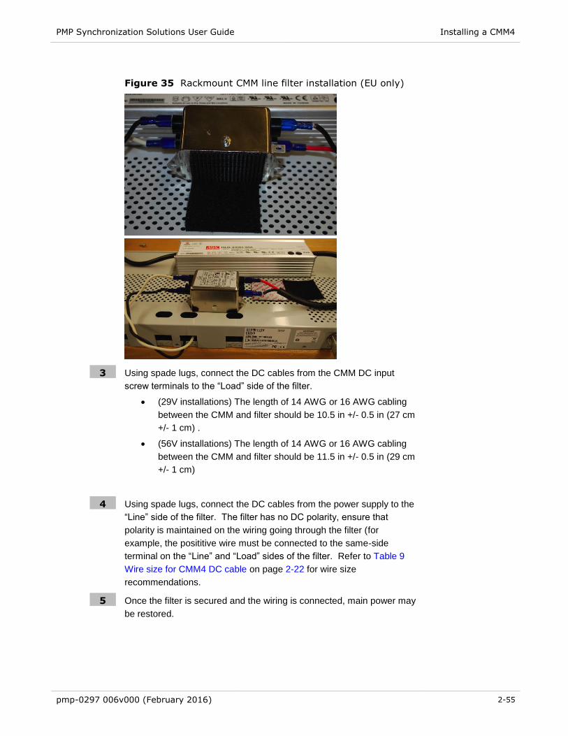
PMP Synchronization Solutions User Guide Installing a CMM4
pmp-0297 006v000 (February 2016) 2-55
Figure 35 Rackmount CMM line filter installation (EU only)
3 Using spade lugs, connect the DC cables from the CMM DC input
screw terminals to the “Load” side of the filter.
(29V installations) The length of 14 AWG or 16 AWG cabling
between the CMM and filter should be 10.5 in +/- 0.5 in (27 cm
+/- 1 cm) .
(56V installations) The length of 14 AWG or 16 AWG cabling
between the CMM and filter should be 11.5 in +/- 0.5 in (29 cm
+/- 1 cm)
4 Using spade lugs, connect the DC cables from the power supply to the
“Line” side of the filter. The filter has no DC polarity, ensure that
polarity is maintained on the wiring going through the filter (for
example, the posititive wire must be connected to the same-side
terminal on the “Line” and “Load” sides of the filter. Refer to Table 9
Wire size for CMM4 DC cable on page 2-22 for wire size
recommendations.
5 Once the filter is secured and the wiring is connected, main power may
be restored.

PMP Synchronization Solutions User Guide Installing a CMM4
pmp-0297 006v000 (February 2016) 2-56
Discontinued power supply notice – ACPS112WA only
The following procedure is only applicable to operators using a CMM4 that supplies power to both 30V
devices (PMP100 radios) and 56V devices (PMP430 or PMP320 radios). The discontinued 30V model
ACPS120WA power supply does NOT require the 1k 5W resistor on the CMM4 29V terminals (This new
30V power supply was made available for order around December 3, 2010). The phased-out 30V model
ACPS112WA power supply will always require a 1k 5W resistor when a 56V supply is present. Since
both power supplies look identical, see the label under the power supply to identify the model.
Power supply model ACPS112WA (discontinued) requires a 1k 5W resistor across the 30V DC input
terminal of the CMM4 when both 30V AND 56V are present. Doing so will prevent the 30V power supply
to not always come out of sleep mode with a light load. The power supply will attempt to come out of
sleep mode, and if it does not see sufficient load it goes into a sleep/recovery cycle that is observable by
watching the 30V LED on the port connector turn on and off.
Power supply Model ACPS120WA (discontinued) satisfies the European Union's Energy Level 5
requirement and DOES NOT require a 1k 5W resistor.
If using both 30 VDC (discontinued model ACPS112WA only) and 56 VDC power, to ensure correct
operation under all conditions a 1000 Ohm 5 W resistor must be installed across the 30 VDC +V and
GND (ground/return) at the terminal block using Procedure 7. The resistor can be purchased locally or
call technical support to obtain one.
The resistor prevents the model ACPS112WA 30 VDC converter (discontinued) from getting stuck in
sleep mode which can occur in dual-powered CMM4s and result in 30 VDC radios getting low voltage
and not booting.
If redundant 30 VDC power supplies are desired along with one or two 56 VDC power supplies, connect
one power supply to each of the 29 VDC terminal blocks using the resistor in one of the 29 VDC terminal
blocks.
Procedure 6 Installing a special resistor for dual-powered CMM4s (30V model
ACPS112WA power supply only)
1 WARNING - Make absolutely sure 30 VDC and 56 VDC converters are unpowered and
disconnected from AC (Mains) before proceeding.
2 Ensure white and black 30 VDC leads have 1/2 in (1 cm) of stranded wiring exposed. Strip
or cut to 1/2 inch if needed.
3 Wrap the stranded wires of the 30 VDC white lead around one of the leads of the 1000
Ohm 5 W resistor.
4 Wrap the stranded wires of the 30 VDC black lead around the other resistor lead.

PMP Synchronization Solutions User Guide Installing a CMM4
pmp-0297 006v000 (February 2016) 2-57
5 Insert the wired resistor assembly into either terminal block labeled "+29 V" as shown
below ensuring that the powered lead is inserted into the correct termination.
Figure 36 Resistor when using both 56 VDC and 30 VDC power
6 Screw terminal block screws down tight. The resistor dissipates 0.9 W and will run warm
at room temperature.
Temperature Range
Install the CMM4 outside only when temperatures are above –4° F (–20° C). The gland openings and the
bushings and inserts in the gland openings are rated for the full –40° to +131° F (–40° to +55° C) range
of the CMM4. However, for dynamic operations (loosening, tightening, and inserting), they are compliant
at, and rated for, only temperatures at or above –4° F (–20° C).
Installing a CMM4 (Models 1090CKHH and 1091HH)
Prizm and Wireless Manager treat the EtherWAN Switch in a CMM4 as a generic switch. For Prizm or
Wireless Manager to correctly associate each EtherWAN Switch with its CMM4
before you install the CMM4, read and note the MAC address of both the CMM4 controller and
EtherWAN switch from the physical units.
after you discover a CMM4 and its switch, use these MAC addresses for moving the switch to the
place in your Prizm or Wireless Manager network view where the CMM4 was discovered.
always maintain a record that associates these two MAC addresses.
IMPORTANT!
When an EMS discovers an EtherWAN switch in your network, it can’t tell which CMM4 the switch is associated with, nor can it tell CMM4 EtherWAN switches from any other EtherWAN switches you may have in your network. The pair of MAC addresses you record directly from the CMM4 and its EtherWAN switch are the only means for you to establish the logical connection.

PMP Synchronization Solutions User Guide Installing a CMM4
pmp-0297 006v000 (February 2016) 2-58
Perform the following procedure to install the CMM4.
Procedure 7 Mounting the CMM4
1 Ensure that the mounting position
is not further than 328 feet (100 meters) from the furthest AP or BH that the CMM4 will serve.
is not closer than 10 feet (3 meters) to the nearest AP or BH.
is not further than 100 feet (30.5 meters) of cable from the intended mounting position of the
GPS antenna.
allows you to fully open the door for service.
2 Select a support structure to which the flanges can be mounted.
3 If the support structure is a wall, use screws or bolts (neither is provided) to attach the flanges to
the wall.
If the support structure is an irregular-shaped object, use adjustable stainless steel bands
(provided) to attach the CMM4 to the object.
If the support structure is a pole that has an outside diameter of 1.25 to 3 inches (3 to 8 cm), use a
toothed V-bracket (provided) to
attach the V-bracket to the pole as shown below.
attach the CMM4 flanges to the V-bracket.
Figure 37 CMM4 V-bracket to pole mounting

PMP Synchronization Solutions User Guide Installing a CMM4
pmp-0297 006v000 (February 2016) 2-59
Installing a Rackmount CMM4 (Model 1092HH)
Perform the following procedure to install the Rackmount CMM4.
Procedure 8 Mounting the Rackmount CMM4
1 Ensure that the mounting position
is not further than 328 feet (100 meters) from the furthest AP or BH that the CMM4 will serve.
is not closer than 10 feet (3 meters) to the nearest AP or BH.
is not further than 100 feet (30.5 meters) of cable from the intended mounting position of the
GPS antenna.
2 Using a T10 Torx driver, attach the mounting two included mounting brackets to the front sides of
the CMM4 module
Figure 38 Attaching the rackmounting brackets
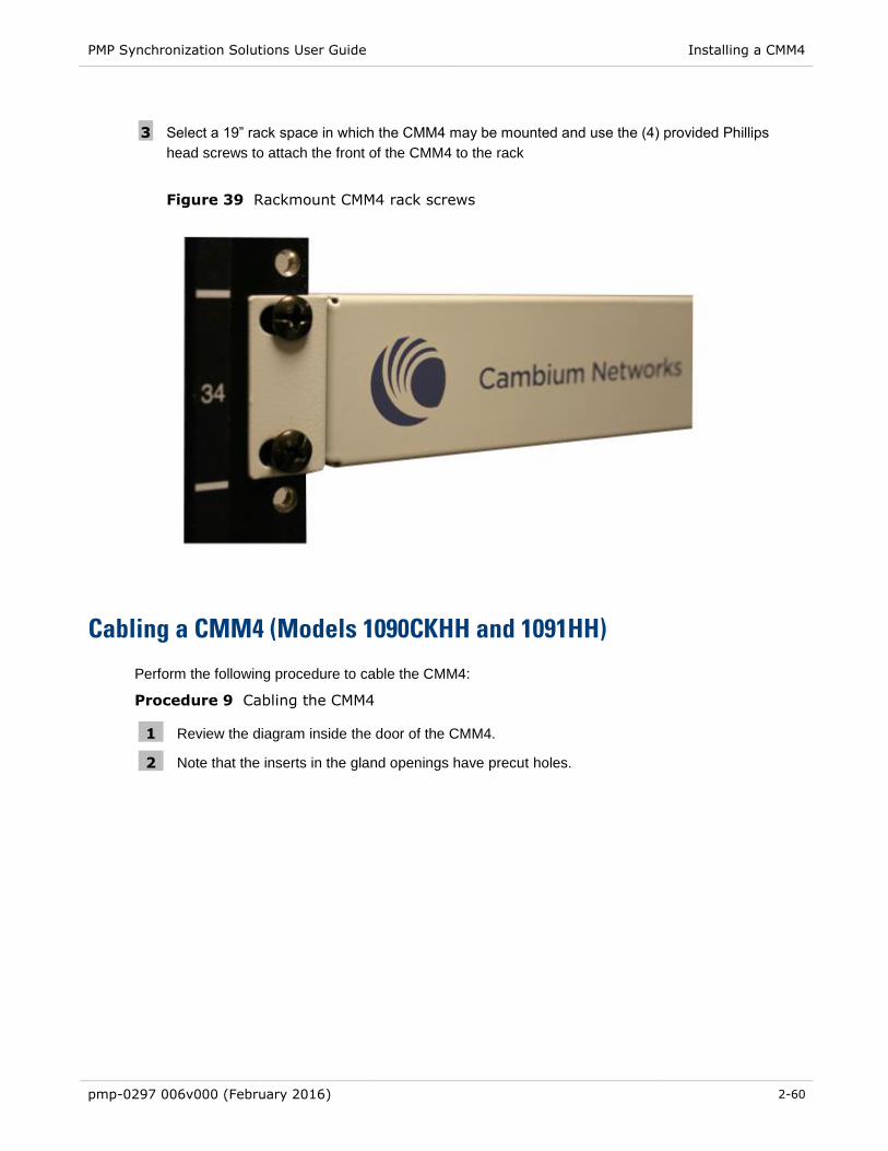
PMP Synchronization Solutions User Guide Installing a CMM4
pmp-0297 006v000 (February 2016) 2-60
3 Select a 19” rack space in which the CMM4 may be mounted and use the (4) provided Phillips
head screws to attach the front of the CMM4 to the rack
Figure 39 Rackmount CMM4 rack screws
Cabling a CMM4 (Models 1090CKHH and 1091HH)
Perform the following procedure to cable the CMM4:
Procedure 9 Cabling the CMM4
1 Review the diagram inside the door of the CMM4.
2 Note that the inserts in the gland openings have precut holes.

PMP Synchronization Solutions User Guide Installing a CMM4
pmp-0297 006v000 (February 2016) 2-61
3 Route Ethernet cables through the cable gland connectors to the Ethernet ports inside the CMM4
cabinet (see the grey cables in Figure 40). Stagger the cables (see Figure 41) to make it easier to
feed them through the gland.
Figure 40 Ethernet port connections
Figure 41 Staggered Ethernet cables

PMP Synchronization Solutions User Guide Installing a CMM4
pmp-0297 006v000 (February 2016) 2-62
4 Connect Ethernet cables as follows (see page 2-11 for typical diagrams and planning
information):
APs, BH10s, or BH20s (PTP 100 Series bridges), PTP 230 Series bridges: cable to
powered ports of the controller board. The controller board provides sync, power, and surge
suppression for these connections. If the CMM4 is mounted inside a building or
communications hut, a Cambium 600SS surge suppressor (model number 600SSC or later)
should be mounted outside the building or communications hut on each line at the point of
cable penetration to prevent over-voltages and over-currents from entering the building and
potentially damaging other electronic equipment.
Terrestrial feeds under 100 Mbps (10/100BaseT): cable to an unpowered port of the
controller board. The controller board provides surge suppression for these connections. If
the CMM4 is mounted inside a building or communications hut, a Cambium 600SS surge
suppressor (model number 600SSC or later) should be mounted outside the building or
communications hut on each line at the point of cable penetration to prevent over-voltages
and over-currents from entering the building and potentially damaging other electronic
equipment.
Terrestrial feeds over 100 Mbps (1000BaseT Gigabit Ethernet): cable directly to the
Gigabit port of the EtherWAN switch, and mount a Cambium PTP-LPU lightning protection
unit or equivalent
o within 3 ft (1 m) of the CMM4 if the CMM4 is located outdoors
o on the outside of the building or communications hut at the point of cable
penetration if the CMM4 is located indoors.
PTP 400 Series bridges: cable to an unpowered port of the controller board. If the CMM4 is
inside a building or communication hut, install the bridge’s PIDU (Powered InDoor Unit) also
inside the building, and install a Hyperlink Technologies AL-CAT6HP-JW surge suppressor
or equivalent on the outside of the building or communications hut at the point of cable
penetration. If the CMM4 is mounted outside, locate the PIDU in a weather-tight enclosure
within 3 ft (1 m) of the CMM4 and install a Hyperlink Technologies AL-CAT6HP-JW surge
suppressor or equivalent within 3 ft (1 m) of the PIDU.
PTP 500 and 600 Series bridges: cable directly to the Gigabit port of the EtherWAN switch.
If the CMM4 is inside a building or communication hut, install the bridge’s PIDU (Powered
InDoor Unit) also inside the building, and install a Hyperlink Technologies AL-CAT6HP-JW
surge suppressor or equivalent on the outside of the building or communications hut at the
point of cable penetration. If the CMM4 is mounted outside, locate the PIDU in a weather-
tight enclosure within 3 ft (1 m) of the CMM4 and install a Hyperlink Technologies AL-
CAT6HP-JW surge suppressor or equivalent within 3 ft (1 m) of the PIDU.
5 On the door label, record the MAC and IP addresses of the CMM4 and all connected equipment.
6 Record also the MAC address of the EtherWAN switch.
7 Consistent with practices in your company, note the above information to add later to the
company equipment database.
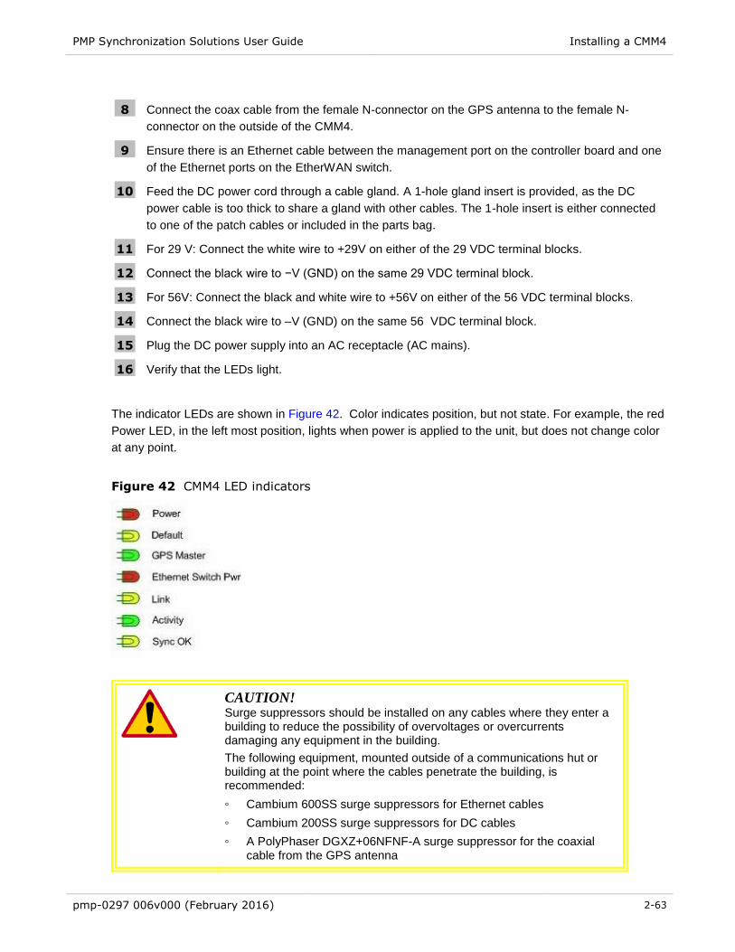
PMP Synchronization Solutions User Guide Installing a CMM4
pmp-0297 006v000 (February 2016) 2-63
8 Connect the coax cable from the female N-connector on the GPS antenna to the female N-
connector on the outside of the CMM4.
9 Ensure there is an Ethernet cable between the management port on the controller board and one
of the Ethernet ports on the EtherWAN switch.
10 Feed the DC power cord through a cable gland. A 1-hole gland insert is provided, as the DC
power cable is too thick to share a gland with other cables. The 1-hole insert is either connected
to one of the patch cables or included in the parts bag.
11 For 29 V: Connect the white wire to +29V on either of the 29 VDC terminal blocks.
12 Connect the black wire to −V (GND) on the same 29 VDC terminal block.
13 For 56V: Connect the black and white wire to +56V on either of the 56 VDC terminal blocks.
14 Connect the black wire to –V (GND) on the same 56 VDC terminal block.
15 Plug the DC power supply into an AC receptacle (AC mains).
16 Verify that the LEDs light.
The indicator LEDs are shown in Figure 42. Color indicates position, but not state. For example, the red
Power LED, in the left most position, lights when power is applied to the unit, but does not change color
at any point.
Figure 42 CMM4 LED indicators
CAUTION!
Surge suppressors should be installed on any cables where they enter a building to reduce the possibility of overvoltages or overcurrents damaging any equipment in the building.
The following equipment, mounted outside of a communications hut or building at the point where the cables penetrate the building, is recommended:
◦ Cambium 600SS surge suppressors for Ethernet cables
◦ Cambium 200SS surge suppressors for DC cables
◦ A PolyPhaser DGXZ+06NFNF-A surge suppressor for the coaxial cable from the GPS antenna

PMP Synchronization Solutions User Guide Installing a CMM4
pmp-0297 006v000 (February 2016) 2-64
Cabling a Rackmount CMM4
Perform the following procedure to cable the Rackmount CMM4:
Procedure 10 Cabling the Rackmount CMM4
1 Connect Ethernet cables as follows (see page 2-11 for typical diagrams and planning
information):
APs, BH10s, or BH20s (PTP 100 Series bridges), PTP 230 Series bridges: cable to
powered ports of the controller board. The controller board provides sync, power, and surge
suppression for these connections. A Cambium 600SS surge suppressor (model number
600SSC or later) should be mounted outside the building or communications hut on each line
at the point of cable penetration to prevent over-voltages and over-currents from entering the
building and potentially damaging other electronic equipment.
Terrestrial feeds under 100 Mbps (10/100BaseT): cable to an unpowered port of the
controller board. The controller board provides surge suppression for these connections. A
Cambium 600SS surge suppressor (model number 600SSC or later) should be mounted
outside the building or communications hut on each line at the point of cable penetration to
prevent over-voltages and over-currents from entering the building and potentially damaging
other electronic equipment.
Terrestrial feeds over 100 Mbps (1000BaseT Gigabit Ethernet): cable directly to the
Gigabit port of the external switch, and mount a Cambium PTP-LPU lightning protection unit
or equivalenton the outside of the building or communications hut at the point of cable
penetration if the CMM4 is located indoors.
PTP 400 Series bridges: cable to an unpowered port of the controller board. Install the
bridge’s PIDU (Powered InDoor Unit) also inside the building, and install a Hyperlink
Technologies AL-CAT6HP-JW surge suppressor or equivalent on the outside of the building
or communications hut at the point of cable penetration.
PTP 500 and 600 Series bridges: cable directly to the Gigabit port of the external switch.
Install the bridge’s PIDU (Powered InDoor Unit) also inside the building, and install a
Hyperlink Technologies AL-CAT6HP-JW surge suppressor or equivalent on the outside of
the building or communications hut at the point of cable penetration.
2 Connect the coax cable from the female N-connector on the GPS antenna to the female N-
connector on the outside of the CMM4.
3 For 29 V: Connect the white wire to +29V on either of the 29 VDC terminal blocks.
4 Connect the black wire to −V (GND) on the same 29 VDC terminal block.
5 For 56V: Connect the black and white wire to +56V on either of the 56 VDC terminal blocks.
6 Connect the black wire to –V (GND) on the same 56 VDC terminal block.
7 Plug the DC power supply into an AC receptacle (AC mains).
8 Verify that the LEDs light.

PMP Synchronization Solutions User Guide Installing a CMM4
pmp-0297 006v000 (February 2016) 2-65
The indicator LEDs are shown in Figure 43. Color indicates position, but not state. For example, the red
Power LED, in the left most position, lights when power is applied to the unit, but does not change color
at any point.
Figure 43 LED indicators - rackmount CMM4
CAUTION!
Surge suppressors should be installed on any cables where they enter a building to reduce the possibility of overvoltages or overcurrents damaging any equipment in the building.
The following equipment, mounted outside of a communications hut or building at the point where the cables penetrate the building, is recommended:
Cambium 600SS surge suppressors for Ethernet cables
Cambium 200SS surge suppressors for DC cables
A PolyPhaser DGXZ+06NFNF-A surge suppressor for the
coaxial cable from the GPS antenna

PMP Synchronization Solutions User Guide Installing a CMM4
pmp-0297 006v000 (February 2016) 2-66
Power Faults
If excessive current is drawn on a port, the analog circuitry reports a PoE fault. The system then turns the
port power off. The power will be restored when the fault is removed.
In this power fault detection system, each port is designed with an electronic fuse that opens the DC
circuit in 26ms if the 1A maximum limit is reached. Then, every 1.7 seconds the fuse will reconnect for
26ms. If the current is less than 1A during the 26ms sampling period, then the fuse will stay connected,
and the port will operate as normal.
Figure 44 shows the port status screen with a power fault on port 1.
Figure 44 CMM port status showing power fault

PMP Synchronization Solutions User Guide
pmp-0297 006v000 (February 2016) 3-1
Chapter 3: Universal Global Positioning System
Module

PMP Synchronization Solutions User Guide UGPS Product Description and Overview
pmp-0297 006v000 (February 2016) 3-2
UGPS Product Description and Overview
The Cambium Networks Universal Global Positioning System (UGPS) is a stand-alone GPS antenna and
receiver with the capability to provide a 1PPS GPS synchronization signal to Cambium Networks access
points (APs), backhaul masters (BHMs), or cluster management modules (CMMs).
The UPGS features two timing ports for sending GPS timing sync. One or two access points/backhaul
masters/cluster management modules may be synchronized directly by the two timing ports.
The UGPS may be used with the following Cambium Networks equipment:
PMP 100 FSK AP
PTP 100 FSK BH
PMP 430 OFDM AP
PMP 400 OFDM AP
PTP 200 OFDM BH
PTP 230 OFDM BH (capable of sourcing power to the UGPS via PTP 230 timing port)
PMP 320 WiMAX AP (AP Software version e2.2 and later)
PMP 450 OFDM AP (capable of sourcing power to the UGPS via PMP 450 timing port)
PTP 450 OFDM BH
CMM3 (CMM3 in Slave mode, CMM3 will receive GPS synchronization pulse, but no GPS location
data)
CMM4 (CMM4 in Slave mode, CMM4 will receive GPS synchronization pulse, but no GPS location
data)
ePMP Series
PMP 450i OFDM AP
PTP 450i OFDM BH

PMP Synchronization Solutions User Guide UGPS Product Description and Overview
pmp-0297 006v000 (February 2016) 3-3
The connector interface for the UGPS is detailed in Figure 45:
Figure 45 UGPS connector interface

PMP Synchronization Solutions User Guide UGPS Power Source Configurations
pmp-0297 006v000 (February 2016) 3-4
UGPS Power Source Configurations
The UGPS module may be powered by an external source via the UGPS External Power Port.
Alternately, the UGPS may be powered by a PTP 230 backhaul master or PMP 450 Platform AP via one
of the UGPS Timing Ports. When the UGPS is powered by via one of the Timing Ports, the radio
provides the necessary power to enable 1 PPS synchronization timing and serial GPS location data by
the UGPS (which is sent back to the radio via the associated Timing Port). If the UGPS is receiving
power on the External Power Port (via 30V DC power supply or CMM port) and power on Timing Port 1
or Timing Port 2 simultaneously, the UGPS defaults to using the external power supply.
External Power Only
Shown below are examples of external only powering for PMP 100 and PMP 400/430 units. In this case
the UGPS is powered via straight-through RJ-45 cable connected to a Cambium approved 30V DC
power supply see Table 27 Compatible 30V Power Supplies on page 3-16 . The UGPS may also
receive power through the RJ-45 Power Port via a power-over-Ethernet port on a CMM4. The radios
receive their GPS synchronization through a straight-through 6-pin RJ-11 cable connected to either
Timing Port 1 or Timing Port 2 of the UGPS.
RJ-45 Pinout for Straight-through Ethernet Power Cable
Figure 46 Power Pinout - UGPS Ethernet Power Cable
Pin 1 white / orange Pin 1
Pin 2 orange Pin 2
Pin 3 white / green Pin 3
Pin 4 blue Pin 4
Pin 5 white / blue Pin 5
Pin 6 green Pin 6
Pin 7 white / brown Pin 7
Pin 8 brown Pin 8
Pins 7 and 8 carry power to the modules.

PMP Synchronization Solutions User Guide UGPS Power Source Configurations
pmp-0297 006v000 (February 2016) 3-5
Figure 47 PMP 100 AP receiving synchronization from external-powered UGPS
Power Supply
Power Supply
IP Default Bypass
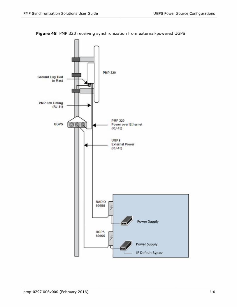
PMP Synchronization Solutions User Guide UGPS Power Source Configurations
pmp-0297 006v000 (February 2016) 3-6
Figure 48 PMP 320 receiving synchronization from external-powered UGPS
29.5V Power Supply
29.5V Power Supply
Power Supply
Power Supply
IP Default Bypass

PMP Synchronization Solutions User Guide UGPS Power Source Configurations
pmp-0297 006v000 (February 2016) 3-7
Figure 49 One PMP 400/430 AP and one PMP 100 AP receiving synchronization from
external-powered UGPS
29.5V Power Supply
29.5V Power Supply
29.5V Power Supply
Power Supply
Power Supply
Power Supply
IP Default Bypass

PMP Synchronization Solutions User Guide UGPS Power Source Configurations
pmp-0297 006v000 (February 2016) 3-8
Power from the Radio via UGPS Timing Port 1 or UGPS Timing Port 2
Shown below is an example of a UGPS unit powered from a PTP 230 BHM through an RJ-11 cable
connected to either Timing Port 1 or Timing Port 2 of the UGPS. The UGPS may be powered by either
Timing Port, and up to two radios may receive synchronization over the Timing Ports when the UGPS is
powered in this fashion.
This UGPS powering mode is currently supported only by PTP 230 BHM and PMP 450 Platform AP.
Future Cambium Networks hardware releases will also support providing power to the UGPS.
When powering the UGPS via AP or BHM, the system uses a straight-through 6-pin RJ-11 cable to
provide power to the UGPS and to retrieve GPS synchronization pulses and data from the UGPS. The
following diagram shows the wiring of the cable for sync and power.
RJ-11 Pinout for Straight-through Sync / Power Cable
Figure 50 Power Pinout - UGPS to AP/BHM Timing Port (6-pin RJ-11)
Pin 1 white / orange Pin 1
Pin 2 white / green Pin 2
Pin 3 white / blue Pin 3
Pin 4 green Pin 4
Pin 5 blue Pin 5
Pin 6 orange Pin 6
1
2
3
4
5
6
1
2
3
4
5
6
1 PPS Sync Pulse (8Vo-p)
N/A
GPS Location Data (8Vo-p)
1 PPS Sync Pulse (8Vo-p)
N/A
GPS Location Data (8Vo-p)
V+ (4V DC – 6V DC)
N/A
V+ (4V DC – 6V DC)
N/A
Pin
Pin RJ-11 Straight-Through
Ground (V+ Return)
Ground (V+ Return)

PMP Synchronization Solutions User Guide UGPS Power Source Configurations
pmp-0297 006v000 (February 2016) 3-9
450i Series AP/BHM to UGPS cable
The 450i Series requires a special cable to connect the AP or BHM to a UGPS module. The AP/BHM to
UGPS cable can be constructed from RJ12 to RJ 45 cable using the ping configuration described in
Table 25.
Figure 51 AP/BHM to UGPS cable
Table 26 AP/BHM to UGPS cable pinout
Pin
450i AP/BHM
RJ 45
Connector
Pin UGPS
RJ 12
Connector
Connector
1 NC 1 8 on RJ 45
2 NC 2 NC
3 NC 3 5 on RJ 45
4 4 on RJ 12 4 4 on RJ 45
5 3 on RJ 12 5 NC
6 NC 6 7 on RJ 45
7 6 on RJ 12
8 1 on RJ 12
NOTE
The AP/BHM will only power up the UGPS if it configured to do so.
``
RJ45 Connector (Bottom) Straight-Through Cable RJ12 Connector (Top)
6
NC 5
4
3
NC 2
1
8
7
6
5
4
3
2
1

PMP Synchronization Solutions User Guide UGPS Power Source Configurations
pmp-0297 006v000 (February 2016) 3-10
Figure 52 PTP 230 backhaul master powering UGPS and receiving synchronization
29.5V Power Supply
IP Default Bypass
Power Supply

PMP Synchronization Solutions User Guide UGPS Power Source Configurations
pmp-0297 006v000 (February 2016) 3-11
Figure 53 PMP 450 AP powering UGPS and receiving synchronization
29.5V Power Supply
IP Default Bypass Note: 450 only, 450i
excluded
Power Supply
IP Default Bypass

PMP Synchronization Solutions User Guide UGPS Power Source Configurations
pmp-0297 006v000 (February 2016) 3-12
Figure 54 Two PTP 230 backhaul master units powering UGPS and receiving
synchronization
29.5V Power Supply
29.5V Power Supply
Power Supply
Power Supply
IP Default Bypass

PMP Synchronization Solutions User Guide UGPS Power Source Configurations
pmp-0297 006v000 (February 2016) 3-13
Figure 55 PTP 230 backhaul master powering UGPS/receiving synchronization and PMP
100/430 receiving synchronization
29.5V Power Supply
29.5V Power Supply
29.5V Power Supply
Power Supply
Power Supply
Power Supply
IP Default Bypass

PMP Synchronization Solutions User Guide UGPS and CMM Configurations
pmp-0297 006v000 (February 2016) 3-14
UGPS and CMM Configurations
The UGPS may be used as a GPS synchronization source for Cambium Networks CMM3 and CMM4
(Cluster Management Module) units. The UGPS provides GPS synchronization to the CMM unit via the
CMM’s sync port. This allows any access points or backhaul masters connected to the CMM to receive
sync. This configuration requires that the CMM3 or CMM4 be configured to “Slave” mode via the CMM
GUI. When using the UGPS as a synchronization source for a CMM3 or CMM4, a special sync cable
must be used. This cable may be constructed from an RJ-11 cable using the pin configuration in Figure
11.
When using a CMM unit, the UGPS may also be used as a redundant sync source for the CMM. If a
CMM encounters an issue with the primary, coaxial-connected GPS receiver an operator may remotely
login to the CMM and set the synchronization source to “Slave” to begin receiving sync from the UGPS
(connected via RJ-11 cable with the pin configuration in section UGPS installation and operation).
PMP 320 Systems - When using both the UGPS for timing and a CMM4 for timing in a PMP 320
network (same AP site or an adjacent AP site), timing discrepancies between the UGPS and CMM4
can cause interference between the sites. To address this issue, operators may opt to use one type of
timing in the network (either UGPS or CMM4). Alternatively, operators may contact technical support to
set up remote access to troubleshoot the AP units that are exhibiting the issue. A future PMP 320
software release will address this timing issue.

PMP Synchronization Solutions User Guide Product Specifications
pmp-0297 006v000 (February 2016) 3-15
Product Specifications
Antenna Frequency Band ..................................... L1 (1575.42 ±10 MHz) Polarization ............................................. Patch
Receiver
Tracking Channels .................................. 12 (Min.) Continuous Tracking Update Rate ........................................... 1 Hz (NMEA) Timing Accuracy (1PPS) ........................ 100ns RMS Position Accuracy ................................... <3 m (Vertical), <10m (Horizontal)
Data Interface
Communications Standard ..................... NMEA-0183 Interface Technology .............................. 1PPS (8Vp-p Level-Shifted Pulse, 100ms Duty Cycle)
TX GPS LOCATION DATA (8Vp-p Level-Shifted – Serial 8/N/1 9600bps )
Acquisition
Cold Start ................................................ 35 seconds (Typical and under open clear sky)
Sensitivity
Acquisition............................................... -148dBm
Tracking ......................................................... -165dBm
Electrical
Voltage.................................................... 4.3V - 6V DC (Timing Ports 1 & 2: +Vap) 10V - 30V DC (External Power Port: +Vext)
Power ...................................................... 250mW (2 APs Loaded; Vap=4.3V DC) 500mW (2 APs Loaded; Vap=0V DC; Vext=30V DC)
Cable Length .......................................... 35m (120 ft.) 2 APs Loaded; Vap(min) = 4.3V DC 100m. (330 ft.) 2 APs Loaded; Vap=0V; Vext=30V DC
Environmental
Operating Temperature .......................... -40C to +85C Humidity .................................................. 95% Ingress Protection ................................... IP67
Mechanical
Dimensions ............................................. 6 inch(Length) x 3.5 inch(Width) x 4 inch(Dome Height) Electrical Interface .................................. RJ11-6 Position Shielded(x2), RJ45-8 Position Shielded Connector ............................................... IP67 Rated Connector (Lapp Cord Grip Style) Weight ..................................................... 15 Oz.

PMP Synchronization Solutions User Guide UGPS installation and operation
pmp-0297 006v000 (February 2016) 3-16
UGPS installation and operation
Observe the following guidelines when installing a UGPS module:
The unit may be pole mounted or surface mounted (on a horizontal surface with an unobstructed view of the sky).
The UGPS should NOT be installed as the highest object at the site.
Orient the GPS antenna so that it has clear access to the southern horizon (if installed north of the equator) or clear access to the northern horizon (if installed south of the equator).
Note locations of 600SS surge suppressors when installing the UGPS unit. Reference UGPS Power Source Configurations diagrams. Compatible power supplies for the UGPS are listed in Table 25.
Observe cable length specifications in Table 26.
Cambium Networks recommends using shielded Category 5E cables for outdoor installations.
The UGPS Power over Ethernet pinout (External Power Port) differs from IEEE Standard 803.3af, and the two should not be intermixed. The UGPS Power over Ethernet pinout is the same as Cambium Networks FSK broadband radios.
Table 27 Compatible 30V Power Supplies and Cords
Model Description
N000900L001A Gigabit Ethernet-Capable Power Supply
N000900L007A Cable, UL PSU Cord Set, US
N000900L008A Cable, UL PSU Cord Set, EU
N000900L009A Cable, UL PSU Cord Set, UK
N000900L010A Cable, UL PSU Cord Set, Brazil
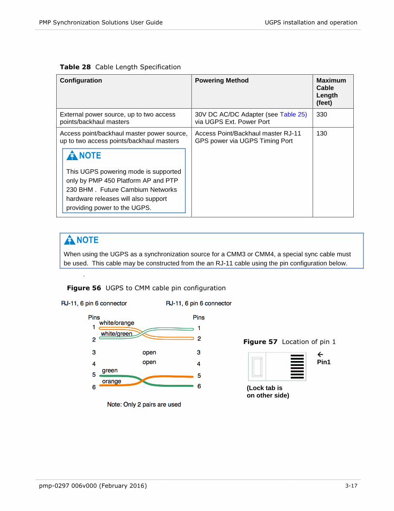
PMP Synchronization Solutions User Guide UGPS installation and operation
pmp-0297 006v000 (February 2016) 3-17
Table 28 Cable Length Specification
Configuration Powering Method Maximum Cable Length (feet)
External power source, up to two access points/backhaul masters
30V DC AC/DC Adapter (see Table 25) via UGPS Ext. Power Port
330
Access point/backhaul master power source, up to two access points/backhaul masters
This UGPS powering mode is supported
only by PMP 450 Platform AP and PTP
230 BHM . Future Cambium Networks
hardware releases will also support
providing power to the UGPS.
Access Point/Backhaul master RJ-11 GPS power via UGPS Timing Port
130
When using the UGPS as a synchronization source for a CMM3 or CMM4, a special sync cable must
be used. This cable may be constructed from the an RJ-11 cable using the pin configuration below.
. Figure 56 UGPS to CMM cable pin configuration
Figure 57 Location of pin 1
(Lock tab is on other side)
Pin1

PMP Synchronization Solutions User Guide UGPS Installation Procedure
pmp-0297 006v000 (February 2016) 3-18
UGPS Installation Procedure
Use the following procedure to install the UGPS module and to verify operation.
Procedure 11 UGPS installation – external-powered
1 Pole mount or surface mount the GPS antenna following the installation guidelines and
specifications listed in this chapter.
2 For PMP 100/400/430/450 and PTP 100/200 series, configure (via web management
interface) the access points/backhaul masters to sync to received GPS signal (via the
timing port). Navigate to Configuration > General and set the Sync Input to Sync to
Received Signal (Timing Port/UGPS). Since the UGPS will be configured with an
external power source, set the UGPS Power value to Disabled.
Figure 58 Configuring the sync input and disabling UGPS power - PMP
100/400/430 and PTP 100/200 series
For PMP 320 series, configure (via web management interface) the access point to
sync to received GPS signal (via the AP’s RJ-11 port). Navigate to Configuration >
Settings and set the Sync Source to UGPS and Serial Type to uGPS.
Figure 59 Configuring the sync source - PMP 320 series

PMP Synchronization Solutions User Guide UGPS Installation Procedure
pmp-0297 006v000 (February 2016) 3-19
3 For PMP 100/400/430/450 and PTP 100/200 series, click Save Changes and reboot
the radio.
For PMP 320 series, click Update, click the Save icon and reboot the radio.
4 If connecting the UGPS to a CMM3 or CMM4, configure the CMM (via the CMM web
management interface) to Slave mode (access points/backhaul masters connected to
the CMM will need to be set to receive GPS sync signal from the power port). Navigate
to Configuration > CMM and set Sync Source to Slave (RJ11 Port). A reboot on the
CMM is required for these changes to take effect.
5 Connect an RJ-11 6 pin cable from Timing Port 1 of the UGPS to the RJ-11 utility port
of the access point/backhaul master to receive GPS sync signal. If applicable, repeat
this step for additional access points and backhaul masters. If the UGPS is to send
sync to a CMM, use a special sync cable constructed per section UGPS installation
and operation.
6 Install a 600SS surge supressor between the power supply and the UGPS module.
Reference the diagrams in section UGPS Power Source Configurations.
7 Connect an RJ-45 8 pin Ethernet cable from the UGPS power port to the 600SS surge
supressor.
8 Connect an RJ-45 8 pin Ethernet cable from the 600SS surge supressor to the power
supply.
9 Verify on the access point/backhaul master/CMM that the GPS synchronization signal
is being received properly. Reference section GPS Status and Location Data Readout.
Procedure 12 UGPS Installation – Powered by AP/BH Timing Port (PMP 450/PTP 230
Only)
1 Pole mount or surface mount the GPS antenna following the installation guidelines
and specifications listed in this chapter.
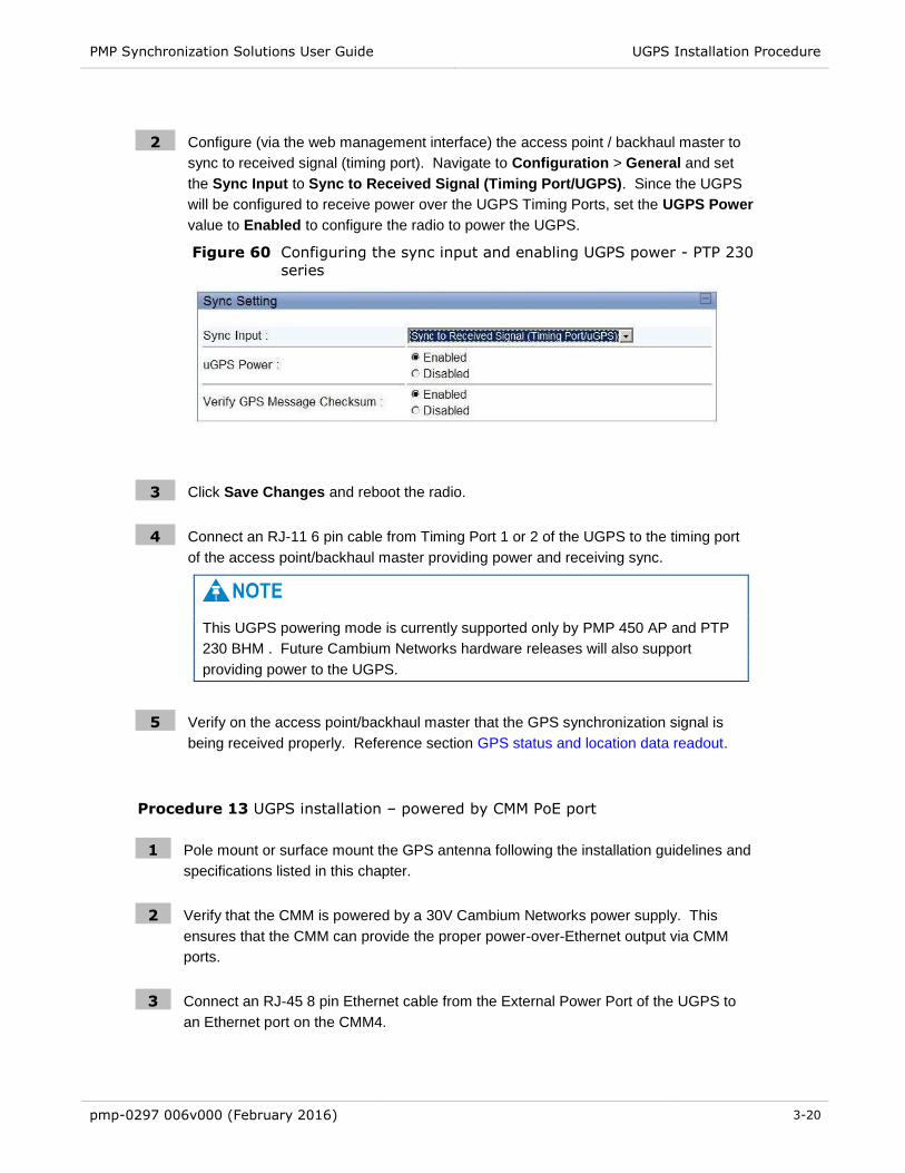
PMP Synchronization Solutions User Guide UGPS Installation Procedure
pmp-0297 006v000 (February 2016) 3-20
2 Configure (via the web management interface) the access point / backhaul master to
sync to received signal (timing port). Navigate to Configuration > General and set
the Sync Input to Sync to Received Signal (Timing Port/UGPS). Since the UGPS
will be configured to receive power over the UGPS Timing Ports, set the UGPS Power
value to Enabled to configure the radio to power the UGPS.
Figure 60 Configuring the sync input and enabling UGPS power - PTP 230
series
Figure
3 Click Save Changes and reboot the radio.
4 Connect an RJ-11 6 pin cable from Timing Port 1 or 2 of the UGPS to the timing port
of the access point/backhaul master providing power and receiving sync.
This UGPS powering mode is currently supported only by PMP 450 AP and PTP
230 BHM . Future Cambium Networks hardware releases will also support
providing power to the UGPS.
5 Verify on the access point/backhaul master that the GPS synchronization signal is
being received properly. Reference section GPS status and location data readout.
Procedure 13 UGPS installation – powered by CMM PoE port
1 Pole mount or surface mount the GPS antenna following the installation guidelines and
specifications listed in this chapter.
2 Verify that the CMM is powered by a 30V Cambium Networks power supply. This
ensures that the CMM can provide the proper power-over-Ethernet output via CMM
ports.
3 Connect an RJ-45 8 pin Ethernet cable from the External Power Port of the UGPS to
an Ethernet port on the CMM4.

PMP Synchronization Solutions User Guide UGPS Installation Procedure
pmp-0297 006v000 (February 2016) 3-21
4 On the CMM4 web management GUI navigate to Configuration > Ports. In this
configuration the CMM4 port connected to the UGPS via RJ-45 cable must be
configured with Power On and Device Type Canopy 29V as Port 1 in Figure 61.
The CMM Ethernet port will only provide 29V power to the UGPS if the CMM is
powered by a 29V power supply. If the CMM is powered by a 56V power supply, it
will not provide 29V power via the PoE ports.
Figure 61 CMM port conifguration for UGPS power
Figur
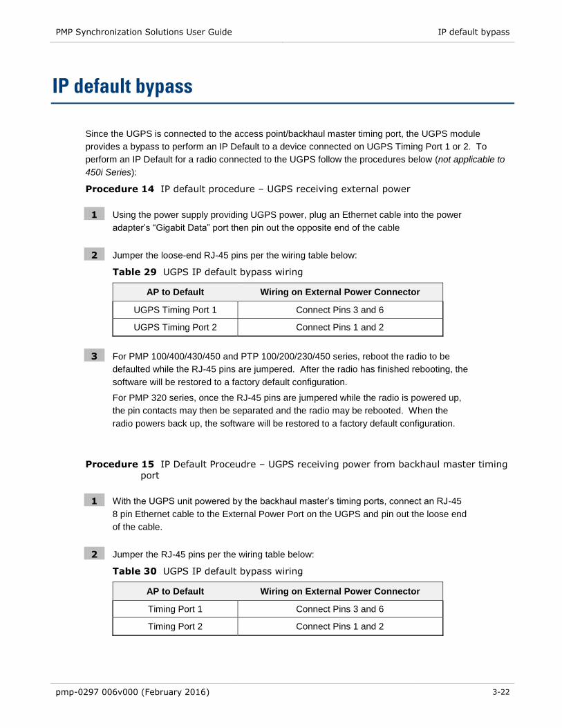
PMP Synchronization Solutions User Guide IP default bypass
pmp-0297 006v000 (February 2016) 3-22
IP default bypass
Since the UGPS is connected to the access point/backhaul master timing port, the UGPS module
provides a bypass to perform an IP Default to a device connected on UGPS Timing Port 1 or 2. To
perform an IP Default for a radio connected to the UGPS follow the procedures below (not applicable to
450i Series):
Procedure 14 IP default procedure – UGPS receiving external power
1 Using the power supply providing UGPS power, plug an Ethernet cable into the power
adapter’s “Gigabit Data” port then pin out the opposite end of the cable
2 Jumper the loose-end RJ-45 pins per the wiring table below:
Table 29 UGPS IP default bypass wiring
AP to Default Wiring on External Power Connector
UGPS Timing Port 1 Connect Pins 3 and 6
UGPS Timing Port 2 Connect Pins 1 and 2
3 For PMP 100/400/430/450 and PTP 100/200/230/450 series, reboot the radio to be
defaulted while the RJ-45 pins are jumpered. After the radio has finished rebooting, the
software will be restored to a factory default configuration.
For PMP 320 series, once the RJ-45 pins are jumpered while the radio is powered up,
the pin contacts may then be separated and the radio may be rebooted. When the
radio powers back up, the software will be restored to a factory default configuration.
Procedure 15 IP Default Proceudre – UGPS receiving power from backhaul master timing
port
1 With the UGPS unit powered by the backhaul master’s timing ports, connect an RJ-45
8 pin Ethernet cable to the External Power Port on the UGPS and pin out the loose end
of the cable.
2 Jumper the RJ-45 pins per the wiring table below:
Table 30 UGPS IP default bypass wiring
AP to Default Wiring on External Power Connector
Timing Port 1 Connect Pins 3 and 6
Timing Port 2 Connect Pins 1 and 2
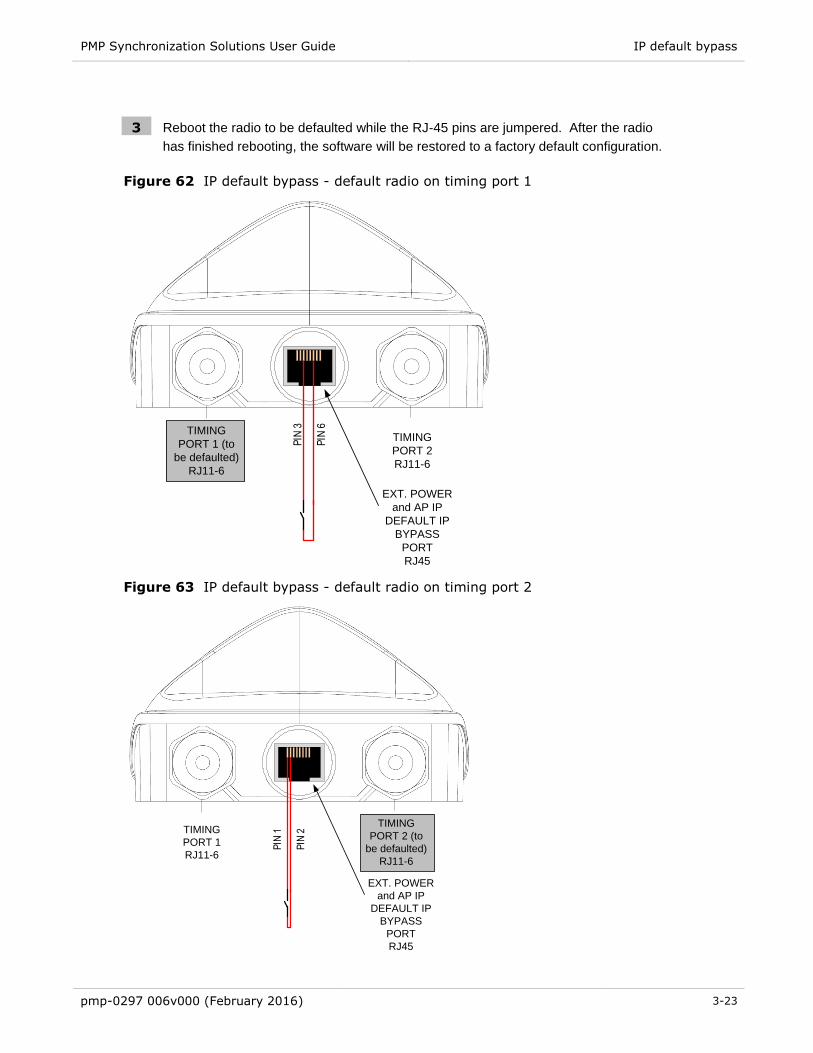
PMP Synchronization Solutions User Guide IP default bypass
pmp-0297 006v000 (February 2016) 3-23
3 Reboot the radio to be defaulted while the RJ-45 pins are jumpered. After the radio
has finished rebooting, the software will be restored to a factory default configuration.
Figure 62 IP default bypass - default radio on timing port 1
PIN
3
PIN
6
TIMING
PORT 1 (to
be defaulted)
RJ11-6
TIMING
PORT 2
RJ11-6
EXT. POWER
and AP IP
DEFAULT IP
BYPASS
PORT
RJ45
Figure 63 IP default bypass - default radio on timing port 2
TIMING
PORT 1
RJ11-6
TIMING
PORT 2 (to
be defaulted)
RJ11-6
EXT. POWER
and AP IP
DEFAULT IP
BYPASS
PORT
RJ45
PIN
1
PIN
2

PMP Synchronization Solutions User Guide GPS status and location data readout
pmp-0297 006v000 (February 2016) 3-24
GPS status and location data readout
The UGPS provides location data to connected synchronized devices and may be retrieved by the
access point/backhaul/cluster management module web GUI or by SNMP. GPS status and location data
readout is currently available on PMP 100/320/400/430, and PTP 100/200/230, series radios.
Retrieving GPS Status and Location Data via Radio Web
Management GUI
Procedure 16 Retrieving GPS status and location data via radio web management GUI –
PMP 100/400/430 and PTP 100/200/230 Series
1 With the UGPS powered and connected to the radio, navigate to Home > GPS Status.
2 GPS Location Data is displayed in section GPS Status.
Figure 64 GPS status and location data - PMP 430 example
Figure

PMP Synchronization Solutions User Guide GPS status and location data readout
pmp-0297 006v000 (February 2016) 3-25
Procedure 17 Retrieving GPS status and location data via radio web management GUI –
PMP 320
1 With the UGPS powered and connected to the radio, navigate to Configuration >
General > Properties.
2 GPS Location Data is displayed as below:
Figure 65 GPS status and location data - PMP 320
Figu
Retrieving GPS status and location data via SNMP
To retrieve GPS Status and Location Data via SNMP (Simple Network Management Protocol) from
synchronized devices operators may use the following procedures.
Procedure 18 Retrieving GPS Status and Location Data via SNMP – PMP 100/400/430 and
PTP 100/200/230 Series
1 With the UGPS powered and connected to the radio, on the radio web management
GUI navigate to Configuration > SNMP.
2 Verify that the Community String and Accessing Subnet values are set as desired.

PMP Synchronization Solutions User Guide GPS status and location data readout
pmp-0297 006v000 (February 2016) 3-26
3 Perform a “snmpget” command for the OID desired based on Table 29.
Table 31 GPS SNMP OIDs - PMP 100/400/430 and PTP 100/200/230 series
Object Name, OID Description
whispGPSStatus,
.1.3.6.1.4.1.161.19.3.1.3.1
GPS synchronization info (1: GPS Synchronized,
2: GPS Lost Sync, 3: Generating Sync)
gpsSyncSource,
.1.3.6.1.4.1.161.19.3.1.3.2
Source of GPS sync pulse
gpsSyncStatus,
.1.3.6.1.4.1.161.19.3.1.3.3
Current GPS sync status
gpsTrackingMode,
.1.3.6.1.4.1.161.19.3.1.3.4
GPS tracking mode
gpsTime,
.1.3.6.1.4.1.161.19.3.1.3.5
GPS time
gpsDate,
.1.3.6.1.4.1.161.19.3.1.3.6
GPS date
gpsSatellitesTracked,
.1.3.6.1.4.1.161.19.3.1.3.7
Current number of satellites GPS is tracking
gpsSatellitesVisible,
.1.3.6.1.4.1.161.19.3.1.3.8
Number of satellites visible to the GPS
gpsHeight,
.1.3.6.1.4.1.161.19.3.1.3.9
GPS height
gpsLatitude,
.1.3.6.1.4.1.161.19.3.1.3.11
GPS latitude
gpsLongitude,
.1.3.6.1.4.1.161.19.3.1.3.12
GPS Longitude

PMP Synchronization Solutions User Guide GPS status and location data readout
pmp-0297 006v000 (February 2016) 3-27
Procedure 19 Retrieving GPS status and location data via SNMP – PMP 320
1 With the UGPS powered and connected to the radio, on the radio web management
GUI navigate to Administration > User Management and verify SNMP user data.
2 Perform a “snmpget” command for the OID desired based on Table 30
Table 32 GPS SNMP OIDs - PMP 320 series
Object Name, OID Description
danSyncStatus,
.1.3.6.1.4.1.32584.1.1.3.2
Source of GPS sync pulse
(0: No sync, 1: Sync present, 2: External
sync missing – operating on internal clock,
3: Transition state - about to lose sync)
danLatitude,
.1.3.6.1.4.1.32584.1.1.1.5
System installation Latitude, Range -90 to
90
danLongitude,
.1.3.6.1.4.1.32584.1.1.1.6
System installation Longitude, Range -180
to 180

PMP Synchronization Solutions User Guide UGPS Power Port and Timing Port Pinouts
pmp-0297 006v000 (February 2016) 3-28
UGPS Power Port and Timing Port Pinouts
See Table 31 and Table 32 below for UGPS pinout information.
Table 33 UGPS Power Port Pinout
Pin Function
1 Ground (for IP Default jumper to Pin 2)
2 Timing Port 2 AP IP Default Pin
3 Ground (For IP Default jumper to Pin 6)
4 Ground (+Vaux Return)
5 Ground (+Vaux Return)
6 Timing Port 1 AP IP Default Pin
7 +Vaux (10V-30V DC)
8 +Vaux (10V-30V DC)
Table 34 UGPS Timing Port Pinout
Pin Function
1 1 PPS Sync Pulse (8Vo-p)
2 N/A
3 GPS Location Data – Serial 9600 bps (8Vo-p)
4 V+ (4V DC – 6V DC)
5 N/A
6 Ground (V+ Return)

PMP Synchronization Solutions User Guide
pmp-0297 006v000 (February 2016) 4-1
Chapter 4: CMM Regulatory and Legal Notices
Important Note on Modifications
Intentional or unintentional changes or modifications to the equipment must not be made unless under
the express consent of the party responsible for compliance. Any such modifications could void the
user’s authority to operate the equipment and will void the manufacturer’s warranty.
PMP Synchronization Solutions User Guide National and Regional Regulatory Notices
pmp-0297 006v000 (February 2016) 4-2
National and Regional Regulatory Notices
U.S. Federal Communication Commission (FCC) Notification
This equipment has been tested and found to comply with the limits for a Class A digital device, pursuant
to Part 15 of the US FCC Rules. These limits are designed to provide reasonable protection against
harmful interference in a residential installation. This equipment generates, uses, and can radiate radio-
frequency energy and, if not installed and used in accordance with these instructions, may cause harmful
interference to radio communications. If this equipment does cause harmful interference to radio or
television reception, which can be determined by turning the equipment on and off, the user is
encouraged to correct the interference by one or more of the following measures:
Increase the separation between the affected equipment and the unit;
Connect the affected equipment to a power outlet on a different circuit from that which the receiver is
connected to;
Consult the dealer and/or experienced radio/TV technician for help.
Industry Canada (IC) Notification
This equipment has been tested and found to comply with the limits for a Class A digital device, pursuant
to RSS-210 of Industry Canada. These limits are designed to provide reasonable protection against
harmful interference in a residential installation. This equipment generates, uses, and can radiate radio-
frequency energy and, if not installed and used in accordance with these instructions, may cause harmful
interference to radio communications. If this equipment does cause harmful interference to radio or
television reception, which can be determined by turning the equipment on and off, the user is
encouraged to correct the interference by one or more of the following measures:
Increase the separation between the affected equipment and the unit;
Connect the affected equipment to a power outlet on a different circuit from that which the receiver is
connected to;
Consult the dealer and/or experienced radio/TV technician for help.
To reduce potential radio interference to other users, the antenna type and its gain should be chosen so
its Equivalent Isotropic Radiated Power (EIRP) is not more than that permitted for successful
communication.

PMP Synchronization Solutions User Guide National and Regional Regulatory Notices
pmp-0297 006v000 (February 2016) 4-3
Equipment Disposal
Waste (Disposal) of Electronic and Electric Equipment
Please do not dispose of Electronic and Electric Equipment or Electronic and Electric Accessories with
your household waste. In some countries or regions, collection systems have been set up to handle
waste of electrical and electronic equipment. In European Union countries, please contact your local
equipment supplier representative or service center for information about the waste collection system in
your country.
EU Declaration of Conformity for RoHS Compliance
Cambium hereby, declares that these Cambium products are in compliance with the essential
requirements and other relevant provisions of Directive 2002/95/EC, Restriction of the use of certain
Hazardous Substances (RoHS) in electrical and electronic equipment.
The relevant Declaration of Conformity can be found at http://www.cambiumnetworks.com/doc.php
Labeling and Disclosure Table for China
The People’s Republic of China requires that Cambium’s products comply with China Management
Methods (CMM) environmental regulations. (China Management Methods refers to the regulation
Management Methods for Controlling Pollution by Electronic Information Products.) Two items are used
to demonstrate compliance; the label and the disclosure table.
The label is placed in a customer visible position on the product.
Logo 1 means that the product contains no substances in excess of the maximum concentration
value for materials identified in the China Management Methods regulation.
Logo 2 means that the product may contain substances in excess of the maximum concentration
value for materials identified in the China Management Methods regulation, and has an
Environmental Friendly Use Period (EFUP) in years, fifty years in the example shown.
Logo 1
Logo 2
The Environmental Friendly Use Period (EFUP) is the period (in years) during which the Toxic and
Hazardous Substances (T&HS) contained in the Electronic Information Product (EIP) will not leak or
mutate causing environmental pollution or bodily injury from the use of the EIP. The EFUP indicated by
the Logo 2 label applies to a product and all its parts. Certain field-replaceable parts, such as battery
modules, can have a different EFUP and are marked separately.
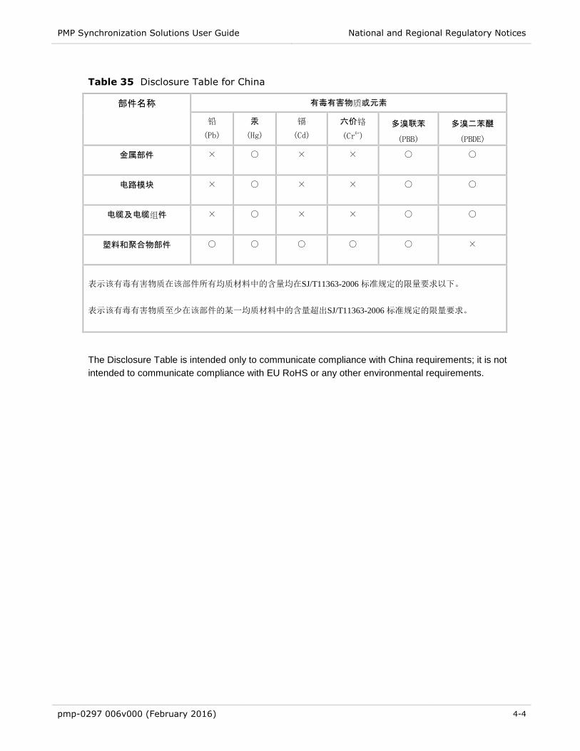
PMP Synchronization Solutions User Guide National and Regional Regulatory Notices
pmp-0297 006v000 (February 2016) 4-4
Table 35 Disclosure Table for China
部件名称 有毒有害物质或元素
铅
(Pb)
汞
(Hg)
镉
(Cd)
六价铬
(Cr6+)
多溴联苯
(PBB)
多溴二苯醚
(PBDE)
金属部件
× ○ × × ○ ○
电路模块
× ○ × × ○ ○
电缆及电缆组件
× ○ × × ○ ○
塑料和聚合物部件
○ ○ ○ ○ ○ ×
表示该有毒有害物质在该部件所有均质材料中的含量均在SJ/T11363-2006 标准规定的限量要求以下。
×: 表示该有毒有害物质至少在该部件的某一均质材料中的含量超出SJ/T11363-2006 标准规定的限量要求。
The Disclosure Table is intended only to communicate compliance with China requirements; it is not
intended to communicate compliance with EU RoHS or any other environmental requirements.

PMP Synchronization Solutions User Guide RF Exposure Separation Distances
pmp-0297 006v000 (February 2016) 4-5
RF Exposure Separation Distances
To protect from overexposure to radio frequency (RF) energy, install Cambium radios so as to provide
and maintain the minimum separation distances from all persons shown in Table 35.
Table 36 Exposure separation distances
Module Type Separation Distance from Persons
Radio Module with integrated antenna At least 20 cm (approx 8 in)
Module with Reflector Dish At least 1.5 m (approx 60 in or 5 ft)
Module with LENS At least 0.5 m (approx 20 in)
Antenna of connectorized 5.7 GHz AP At least 30 cm (approx 12 in)
Antenna of connectorized or integrated 900 MHz module
At least 60 cm (24 in)
Indoor 900 MHz SM At least 10 cm (4 in)
PMP 320 AP At least 50 cm (20 in)
For details and discussion of the associated calculations, see the Canopy System Release 9.4.2 User’s
Guide, available at http://www.cambiumnetworks.com/support

PMP Synchronization Solutions User Guide Legal Notices
pmp-0297 006v000 (February 2016) 4-6
Legal Notices
Software License Terms and Conditions
ONLY OPEN THE PACKAGE, OR USE THE SOFTWARE AND RELATED PRODUCT IF YOU ACCEPT
THE TERMS OF THIS LICENSE. BY BREAKING THE SEAL ON THIS DISK KIT / CDROM, OR IF YOU
USE THE SOFTWARE OR RELATED PRODUCT, YOU ACCEPT THE TERMS OF THIS LICENSE
AGREEMENT. IF YOU DO NOT AGREE TO THESE TERMS, DO NOT USE THE SOFTWARE OR
RELATED PRODUCT; INSTEAD, RETURN THE SOFTWARE TO PLACE OF PURCHASE FOR A FULL
REFUND. THE FOLLOWING AGREEMENT IS A LEGAL AGREEMENT BETWEEN YOU (EITHER AN
INDIVIDUAL OR ENTITY), AND CAMBIUM, INC. (FOR ITSELF AND ITS LICENSORS). THE RIGHT
TO USE THIS PRODUCT IS LICENSED ONLY ON THE CONDITION THAT YOU AGREE TO THE
FOLLOWING TERMS.
Now, therefore, in consideration of the promises and mutual obligations contained herein, and for other
good and valuable consideration, the receipt and sufficiency of which are hereby mutually acknowledged,
you and Cambium agree as follows:
Grant of License. Subject to the following terms and conditions, Cambium, Inc., grants to you a
personal, revocable, non-assignable, non-transferable, non-exclusive and limited license to use on a
single piece of equipment only one copy of the software contained on this disk (which may have been
pre-loaded on the equipment)(Software). You may make two copies of the Software, but only for backup,
archival, or disaster recovery purposes. On any copy you make of the Software, you must reproduce
and include the copyright and other proprietary rights notice contained on the copy we have furnished
you of the Software.
Ownership. Cambium (or its supplier) retains all title, ownership and intellectual property rights to the
Software and any copies, including translations, compilations, derivative works (including images) partial
copies and portions of updated works. The Software is Cambium’s (or its supplier's) confidential
proprietary information. This Software License Agreement does not convey to you any interest in or to
the Software, but only a limited right of use. You agree not to disclose it or make it available to anyone
without Cambium’s written authorization. You will exercise no less than reasonable care to protect the
Software from unauthorized disclosure. You agree not to disassemble, decompile or reverse engineer, or
create derivative works of the Software, except and only to the extent that such activity is expressly
permitted by applicable law.
Termination. This License is effective until terminated. This License will terminate immediately without
notice from Cambium or judicial resolution if you fail to comply with any provision of this License. Upon
such termination you must destroy the Software, all accompanying written materials and all copies
thereof, and the sections entitled Limited Warranty, Limitation of Remedies and Damages, and General
will survive any termination.

PMP Synchronization Solutions User Guide Legal Notices
pmp-0297 006v000 (February 2016) 4-7
Limited Warranty. Cambium warrants for a period of ninety (90) days from Cambium’s or its customer’s
shipment of the Software to you that (i) the disk(s) on which the Software is recorded will be free from
defects in materials and workmanship under normal use and (ii) the Software, under normal use, will
perform substantially in accordance with Cambium’s published specifications for that release level of the
Software. The written materials are provided "AS IS" and without warranty of any kind. Cambium's
entire liability and your sole and exclusive remedy for any breach of the foregoing limited warranty will
be, at Cambium's option, replacement of the disk(s), provision of downloadable patch or replacement
code, or refund of the unused portion of your bargained for contractual benefit up to the amount paid for
this Software License.
THIS LIMITED WARRANTY IS THE ONLY WARRANTY PROVIDED BY CAMBIUM, AND CAMBIUM
AND ITS LICENSORS EXPRESSLY DISCLAIM ALL OTHER WARRANTIES, EITHER EXPRESS OF
IMPLIED, INCLUDING BUT NOT LIMITED TO IMPLIED WARRANTIES OF MERCHANTABILITY AND
FITNESS FOR A PARTICULAR PURPOSE AND NONINFRINGEMENT. CAMBIUM DOES NOT
WARRANT THAT THE OPERATION OF THE SOFTWARE WILL BE UNINTERRUPTED OR ERROR-
FREE, OR THAT DEFECTS IN THE SOFTWARE WILL BE CORRECTED. NO ORAL OR WRITTEN
REPRESENTATIONS MADE BY CAMBIUM OR AN AGENT THEREOF SHALL CREATE A
WARRANTY OR IN ANY WAY INCREASE THE SCOPE OF THIS WARRANTY. CAMBIUM DOES NOT
WARRANT ANY SOFTWARE THAT HAS BEEN OPERATED IN EXCESS OF SPECIFICATIONS,
DAMAGED, MISUSED, NEGLECTED, OR IMPROPERLY INSTALLED. BECAUSE SOME
JURISDICTIONS DO NOT ALLOW THE EXCLUSION OR LIMITATION OF IMPLIED WARRANTIES,
THE ABOVE LIMITATIONS MAY NOT APPLY TO YOU.
Limitation of Remedies and Damages. Regardless of whether any remedy set forth herein fails of its
essential purpose, IN NO EVENT SHALL CAMBIUM OR ANY OF THE LICENSORS, DIRECTORS,
OFFICERS, EMPLOYEES OR AFFILIATES OF THE FOREGOING BE LIABLE TO YOU FOR ANY
CONSEQUENTIAL, INCIDENTAL, INDIRECT, SPECIAL OR SIMILAR DAMAGES WHATSOEVER
(including, without limitation, damages for loss of business profits, business interruption, loss of business
information and the like), whether foreseeable or unforeseeable, arising out of the use or inability to use
the Software or accompanying written materials, regardless of the basis of the claim and even if
Cambium or a Cambium representative has been advised of the possibility of such damage. Cambium's
liability to you for direct damages for any cause whatsoever, regardless of the basis of the form of the
action, will be limited to the price paid for the Software that caused the damages. THIS LIMITATION
WILL NOT APPLY IN CASE OF PERSONAL INJURY ONLY WHERE AND TO THE EXTENT THAT
APPLICABLE LAW REQUIRES SUCH LIABILITY. BECAUSE SOME JURISDICTIONS DO NOT
ALLOW THE EXCLUSION OR LIMITATION OF LIABILITY FOR CONSEQUENTIAL OR INCIDENTAL
DAMAGES, THE ABOVE LIMITATION MAY NOT APPLY TO YOU.
Maintenance and Support. Cambium shall not be responsible for maintenance or support of the
software. By accepting the license granted under this agreement, you agree that Cambium will be under
no obligation to provide any support, maintenance or service in connection with the Software or any
application developed by you. Any maintenance and support of the Related Product will be provided
under the terms of the agreement for the Related Product.

PMP Synchronization Solutions User Guide Legal Notices
pmp-0297 006v000 (February 2016) 4-8
Transfer. In the case of software designed to operate on Cambium equipment, you may not transfer the
Software to another party except: (1) if you are an end-user, when you are transferring the Software
together with the Cambium equipment on which it operates; or 2) if you are a Cambium licensed
distributor, when you are transferring the Software either together with such Cambium equipment or are
transferring the Software as a licensed duly paid for upgrade, update, patch, new release, enhancement
or replacement of a prior version of the Software. If you are a Cambium licensed distributor, when you
are transferring the Software as permitted herein, you agree to transfer the Software with a license
agreement having terms and conditions no less restrictive than those contained herein. You may
transfer all other Software, not otherwise having an agreed restriction on transfer, to another party.
However, all such transfers of Software are strictly subject to the conditions precedent that the other
party agrees to accept the terms and conditions of this License, and you destroy any copy of the
Software you do not transfer to that party. You may not sublicense or otherwise transfer, rent or lease
the Software without our written consent. You may not transfer the Software in violation of any laws,
regulations, export controls or economic sanctions imposed by the US Government.
Right to Audit. Cambium shall have the right to audit annually, upon reasonable advance notice and
during normal business hours, your records and accounts to determine compliance with the terms of this
Agreement.
Export Controls. You specifically acknowledge that the software may be subject to United States and
other country export control laws. You shall comply strictly with all requirements of all applicable export
control laws and regulations with respect to all such software and materials.
US Government Users. If you are a US Government user, then the Software is provided with
"RESTRICTED RIGHTS" as set forth in subparagraphs (c)(1) and (2) of the Commercial Computer
Software-Restricted Rights clause at FAR 52 227-19 or subparagraph (c)(1)(ii) of the Rights in Technical
Data and Computer Software clause at DFARS 252.227-7013, as applicable.
Disputes. You and Cambium hereby agree that any dispute, controversy or claim, except for any
dispute, controversy or claim involving intellectual property, prior to initiation of any formal legal process,
will be submitted for non-binding mediation, prior to initiation of any formal legal process. Cost of
mediation will be shared equally. Nothing in this Section will prevent either party from resorting to judicial
proceedings, if (i) good faith efforts to resolve the dispute under these procedures have been
unsuccessful, (ii) the dispute, claim or controversy involves intellectual property, or (iii) interim relief from
a court is necessary to prevent serious and irreparable injury to that party or to others.
General. Illinois law governs this license. The terms of this license are supplemental to any written
agreement executed by both parties regarding this subject and the Software Cambium is to license you
under it, and supersedes all previous oral or written communications between us regarding the subject
except for such executed agreement. It may not be modified or waived except in writing and signed by an
officer or other authorized representative of each party. If any provision is held invalid, all other
provisions shall remain valid, unless such invalidity would frustrate the purpose of our agreement. The
failure of either party to enforce any rights granted hereunder or to take action against the other party in
the event of any breach hereunder shall not be deemed a waiver by that party as to subsequent
enforcement of rights or subsequent action in the event of future breaches.

PMP Synchronization Solutions User Guide Legal Notices
pmp-0297 006v000 (February 2016) 4-9
Hardware Warranty in U.S.
Cambium’s standard hardware warranty is for one (1) year from date of shipment from Cambium or a
Cambium distributor. Cambium warrants that hardware will conform to the relevant published
specifications and will be free from material defects in material and workmanship under normal use and
service. Cambium shall within this time, at its own option, either repair or replace the defective product
within thirty (30) days of receipt of the defective product. Repaired or replaced product will be subject to
the original warranty period but not less than thirty (30) days.
For warranty assistance, contact the reseller or distributor.
Using non-Cambium parts for repair could damage the equipment or void warranty. Contact Cambium for service
and repair instructions.
Portions of Cambium equipment may be damaged from exposure to electrostatic discharge. Use precautions to
prevent damage.
Limit of Liability
IN NO EVENT SHALL CAMBIUM BE LIABLE TO YOU OR ANY OTHER PARTY FOR ANY DIRECT,
INDIRECT, GENERAL, SPECIAL, INCIDENTAL, CONSEQUENTIAL, EXEMPLARY OR OTHER
DAMAGE ARISING OUT OF THE USE OR INABILITY TO USE THE PRODUCT (INCLUDING,
WITHOUT LIMITATION, DAMAGES FOR LOSS OF BUSINESS PROFITS, BUSINESS
INTERRUPTION, LOSS OF BUSINESS INFORMATION OR ANY OTHER PECUNIARY LOSS, OR
FROM ANY BREACH OF WARRANTY, EVEN IF CAMBIUM HAS BEEN ADVISED OF THE
POSSIBILITY OF SUCH DAMAGES. (Some states do not allow the exclusion or limitation of incidental
or consequential damages, so the above exclusion or limitation may not apply to you.) IN NO CASE
SHALL CAMBIUM’S LIABILITY EXCEED THE AMOUNT YOU PAID FOR THE PRODUCT.

PMP Synchronization Solutions User Guide
pmp-0297 006v000 (February 2016) 5-1
Chapter 5: UGPS Regulatory, Legal, and Safety
Notices
IMPORTANT NOTE ON MODIFICATIONS
Intentional or unintentional changes or modifications to the equipment must not be made unless under
the express consent of the party responsible for compliance. Any such modifications could void the
user’s authority to operate the equipment and voids the manufacturer’s warranty.
Universal GPS module label
Figure 66 UGPS label
NATIONAL AND REGIONAL REGULATORY NOTICES
U.S. Federal Communication Commission (FCC) Notification
This device complies with Part 15 of the US FCC Rules and Regulations. Operation is subject to the
following two conditions:
1. This device may not cause harmful interference and
2. This device must accept any interference received, including interference that may cause undesired operation.

PMP Synchronization Solutions User Guide Legal Notices
pmp-0297 006v000 (February 2016) 5-2
This equipment has been tested and found to comply with the limits for a Class B digital device, pursuant
to Part 15 of the US FCC Rules. These limits are designed to provide reasonable protection against
harmful interference in a residential installation. This equipment generates, uses, and can radiate radio-
frequency energy and, if not installed and used in accordance with these instructions, may cause harmful
interference to radio communications. If this equipment does cause harmful interference to radio or
television reception, which can be determined by turning the equipment on and off, the user is
encouraged to correct the interference by one or more of the following measures:
Increase the separation between the affected equipment and the unit;
Connect the affected equipment to a power outlet on a different circuit from that which the receiver is
connected to;
Consult the dealer and/or experienced radio/TV technician for help.
Industry Canada Notification
This Category II radio communication device complies with Industry Canada Standard RSS-310.
Ce dispositif de radiocommunication de catégorie II respecte la norme CNR-310 d’Industrie Canada.
Operation is subject to the following two conditions:
This device may not cause harmful interference and
This device must accept any interference received, including interference that may cause undesired
operation.
This equipment has been tested and found to comply with the limits for a Class B digital device. These
limits are designed to provide reasonable protection against harmful interference in a residential
installation. This equipment generates, uses, and can radiate radio-frequency energy and if not installed
and used in accordance with these instructions, may cause harmful interference to radio
communications. If this equipment does cause harmful interference to radio or television reception, which
can be determined by turning the equipment on and off, the user is encouraged to correct the
interference by one or more of the following measures:
Increase the separation between the affected equipment and the unit;
Connect the affected equipment to a power outlet on a different circuit from that which the receiver is
connected to;
Consult the dealer and/or experienced radio/TV technician for help

PMP Synchronization Solutions User Guide Legal Notices
pmp-0297 006v000 (February 2016) 5-3
Equipment Disposal
Figure 67 Waste disposal of electronic and electric equipment
Please do not dispose of Electronic and Electric Equipment or Electronic and Electric Accessories with
your household waste. In some countries or regions, collection systems have been set up to handle
waste of electrical and electronic equipment. In European Union countries, please contact your local
equipment supplier representative or service center for information about the waste collection system in
your country.
LIMIT OF LIABILITY
IN NO EVENT SHALL CAMBIUM NETWORKS BE LIABLE TO YOU OR ANY OTHER PARTY FOR ANY
DIRECT, INDIRECT, GENERAL, SPECIAL, INCIDENTAL, CONSEQUENTIAL, EXEMPLARY OR
OTHER DAMAGE ARISING OUT OF THE USE OR INABILITY TO USE THE PRODUCT (INCLUDING,
WITHOUT LIMITATION, DAMAGES FOR LOSS OF BUSINESS PROFITS, BUSINESS
INTERRUPTION, LOSS OF BUSINESS INFORMATION OR ANY OTHER PECUNIARY LOSS, OR
FROM ANY BREACH OF WARRANTY, EVEN IF CAMBIUM NETWORKS HAS BEEN ADVISED OF
THE POSSIBILITY OF SUCH DAMAGES. (Some states do not allow the exclusion or limitation of
incidental or consequential damages, so the above exclusion or limitation may not apply to you.) IN NO
CASE SHALL CAMBIUM NETWORKS LIABILITY EXCEED THE AMOUNT YOU PAID FOR THE
PRODUCT.