Embed Size (px)
Citation preview
1
PMP IWG BRAKE PARTICLE EMISSIONS
BRAKE EMISSION TASK FORCE 2 (TF2)
MINIMUM SPECIFICATIONS FOR TESTING
Theo Grigoratos and TF2 members
PMP Webconference 15 July 2021
2
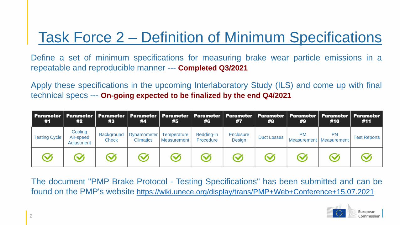
Task Force 2 – Definition of Minimum Specifications
Define a set of minimum specifications for measuring brake wear particle emissions in a
repeatable and reproducible manner --- Completed Q3/2021
Apply these specifications in the upcoming Interlaboratory Study (ILS) and come up with final
technical specs --- On-going expected to be finalized by the end Q4/2021
Parameter
#1
Parameter
#2
Parameter
#3
Parameter
#4
Parameter
#5
Parameter
#6
Parameter
#7
Parameter
#8
Parameter
#9
Parameter
#10
Parameter
#11
Testing Cycle
Cooling
Air-speed
Adjustment
Background
Check
Dynamometer
Climatics
Temperature
Measurement
Bedding-in
Procedure
Enclosure
Design Duct Losses
PM
Measurement
PN
Measurement Test Reports
The document "PMP Brake Protocol - Testing Specifications" has been submitted and can be
found on the PMP's website https://wiki.unece.org/display/trans/PMP+Web+Conference+15.07.2021
3
Task Force 2 – Minimum Specifications
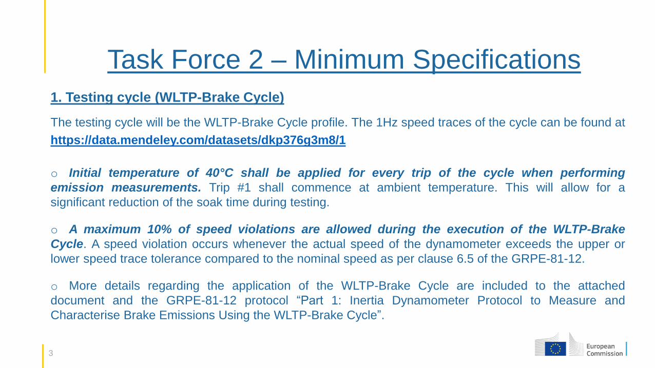
1. Testing cycle (WLTP-Brake Cycle)
The testing cycle will be the WLTP-Brake Cycle profile. The 1Hz speed traces of the cycle can be found at
https://data.mendeley.com/datasets/dkp376g3m8/1
o Initial temperature of 40°C shall be applied for every trip of the cycle when performing
emission measurements. Trip #1 shall commence at ambient temperature. This will allow for a
significant reduction of the soak time during testing.
o A maximum 10% of speed violations are allowed during the execution of the WLTP-Brake
Cycle. A speed violation occurs whenever the actual speed of the dynamometer exceeds the upper or
lower speed trace tolerance compared to the nominal speed as per clause 6.5 of the GRPE-81-12.
o More details regarding the application of the WLTP-Brake Cycle are included to the attached
document and the GRPE-81-12 protocol “Part 1: Inertia Dynamometer Protocol to Measure and
Characterise Brake Emissions Using the WLTP-Brake Cycle”.
4
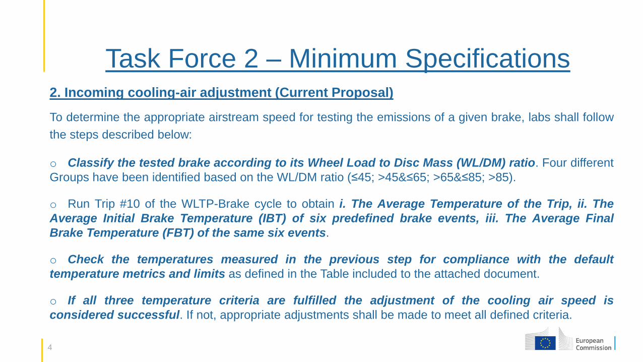
Task Force 2 – Minimum Specifications 2. Incoming cooling-air adjustment (Current Proposal)
To determine the appropriate airstream speed for testing the emissions of a given brake, labs shall follow
the steps described below:
o Classify the tested brake according to its Wheel Load to Disc Mass (WL/DM) ratio. Four different
Groups have been identified based on the WL/DM ratio (≤45; >45&≤65; >65&≤85; >85).
o Run Trip #10 of the WLTP-Brake cycle to obtain i. The Average Temperature of the Trip, ii. The
Average Initial Brake Temperature (IBT) of six predefined brake events, iii. The Average Final
Brake Temperature (FBT) of the same six events.
o Check the temperatures measured in the previous step for compliance with the default
temperature metrics and limits as defined in the Table included to the attached document.
o If all three temperature criteria are fulfilled the adjustment of the cooling air speed is
considered successful. If not, appropriate adjustments shall be made to meet all defined criteria.
5
Task Force 2 – Minimum Specifications 3. Background concentration check
Each lab shall follow the recommendations described below regarding the background concentration
check.
o The cooling air entering the brake enclosure during a brake particle emission test shall pass through a
medium capable of reducing particles of the most penetrating particle size in the filter material by at least
99.95%, or through a filter of at least class H13 as specified in EN 1822.
o The background concentration shall be defined on a PN basis. Each laboratory shall report their
background concentration for each cooling setting. The background concentration shall not exceed the
maximum allowed value of X particles/km (to be defined after the ILS).
o The background check shall be performed at two levels. The first level foresees the system
installation (or when there are indications of malfunction), while the second level foresees regular
background checks before and after the execution of a brake emissions test.
6
Task Force 2 – Minimum Specifications 4. Dyno climatics
The incoming cooling air temperature and relative humidity (RH) shall be set to 20°C and 50%,
respectively.
o Emission tests shall be considered successful when the average temperature of the incoming cooling
air during the test falls within ±2°C with respect to the target value (i.e. 20±2°C) AND when the average
relative humidity of the incoming cooling air during the test falls within ±5% of the target value (i.e.
50±5%).
o The temperature and relative humidity of the incoming cooling air are allowed to oscillate between
20±5°C and 50±10%, respectively, for no longer than the 10% duration of the cycle provided that the
average targets as defined above are met.
o The same temperature and relative humidity requirements for the incoming cooling air as described
above shall apply during the bedding procedure as well as during the cooling air adjustment
procedure.
7
Task Force 2 – Minimum Specifications 5. Brake temperature measurement method
Embedded thermocouples shall be used for measuring brake disc and drum temperature. Disc
temperature shall be used to control the test temperatures and initiate individual trips of the WLTP-Brake
Cycle. It shall also be used to define target parameters during cooling adjustment
o The disc thermocouple shall be located in the outboard plate rubbing surface recessed
(0.5±0.1) mm deep into the face of the disc. The drum thermocouple shall be located at the centre of
the friction path (0.5±0.1) mm deep in the inside surface of the brake drum.
o Brake pad or shoe temperature measurement is also recommended in parallel to the disc
measurement. It is recommended to embed one thermocouple at a depth of 1.0 mm near the center of
the friction surface on each pad or in case of drum brakes near the centre of the friction surface of the
most heavily loaded shoe.
o Sliding thermocouples may be used for research or other purposes; however, always complementary
to the embedded thermocouples.
8
Task Force 2 – Minimum Specifications 6. Definition of bedding-in procedure
Bedding shall be long enough to ensure the stabilization of the brake's emission behavior. However, there
needs to be a compromise to keep test duration at reasonable levels.
o It is recommended to apply 5 WLTP-Brake Cycles for bedding disc/pad couples and drum
brakes. The number of cycles required might be revised after the ILS.
o The 5 WLTP-based novel cycles shall run consecutively without any interruption. Soak times shall
not apply between the individual trips during the bedding procedure. Each repetition shall
commence at 40°C (1st repetition at ambient temperature).
o The bedding procedure shall take place on the same dynamometer as the actual emissions
measurement without disassembling the parts between the two procedures. This is to avoid
modifying the contact points and subsequently the emissions behaviour.
o An alternative protocol of 10 repetitions of Trip #10 of the WLTP-Brake Cycle will be tested at
the ILS for its suitability as a bedding procedure.
9
Task Force 2 – Minimum Specifications 7. Brake enclosure design
Design requirements for the enclosure are defined with the aim of achieving maximum transport
efficiency, maximum particle distribution/uniformity, and minimum residence time.
o The brake enclosure shall incorporate good aerosol sampling practice that includes the use of smooth
internal surfaces and the avoidance of sharp bends and abrupt changes in cross-section.
o The brake enclosure shall come in dimensions which allow for measurements of all common
sizes of LDV brake assemblies.
o It is recommended to install the caliper at the upper part of the disc in a position between 1 and
2 o´clock or 10 and 11 o´clock considering the direction of evacuation.
o The brake disc shall rotate in the direction of the evacuation (CW or CCW) independently of the
orientation of the duct works (horizontal or vertical).
10
Task Force 2 – Minimum Specifications 8. Estimation of duct and sampling train losses
Each lab shall report the estimation of the particle losses in the duct and the sampling train (from the tip of
the sampling nozzle to the entry port of the given instrument or sampling device) based on calculations
performed in house. Available options include but not limited to.
o Estimation of the losses by means of LINK PALS Macro (Optional).
o CFD studies (Optional)
o Particle size distribution (Optional)
11
Task Force 2 – Minimum Specifications 9. PM mass measurement
Brake PM10 and PM2.5 mass emissions shall be measured gravimetrically. Minimum specifications and
recommendations on the following aspects have been defined.
o Transport and Extraction – Include specs about the positioning of the sampling plane, the selection
and positioning of nozzles to ensure isokinetic sampling, the measument of air-speed, the use of flow
splitters, etc.
o PM Sampling Devices and Media – Including specs about the potential use of pre-classifiers and
classifiers, their minimum requirements, the types of filters and substrates depending on the PM sampling
device, etc.
o Weighing Procedure – Including specs about the pre-sampling and the post-sampling conditioning of
the substrates, the weighing room and balance, the storage and tranfer conditions, the use of reference
filters, etc.
12
Task Force 2 – Minimum Specifications 10. PN concentration measurement
The Particle Number (PN) measurement system shall consist of a pre-classifier, a sampling line, a diluter,
and a Condensation Particle Counter (CPC). Minimum specifications have been defined for these
o A pre-classifier with a cut-off point between 2.5-10 μm (recommendation to select one with a low
cut-off) shall be used to protect the PN system from contamination.
o The diluter shall ensure that sufficient dilution is employed to avoid CPC saturation. The CPC
concentration during tests shall not exceed the maximum concentration employed during linearity
calibration.
o The CPC shall be full flow and in accordance with the specifications of GTR15 for 10 nm
measurements. These include a counting efficiency of 65% (±15%) at 10 nm and >90% at 15 nm.
o It is recommended to also measure Solid PN (SPN) in parallel to the total PN concentrations.
Thermal treatment of the sample should be done following the specifications described in GTR 15.
13
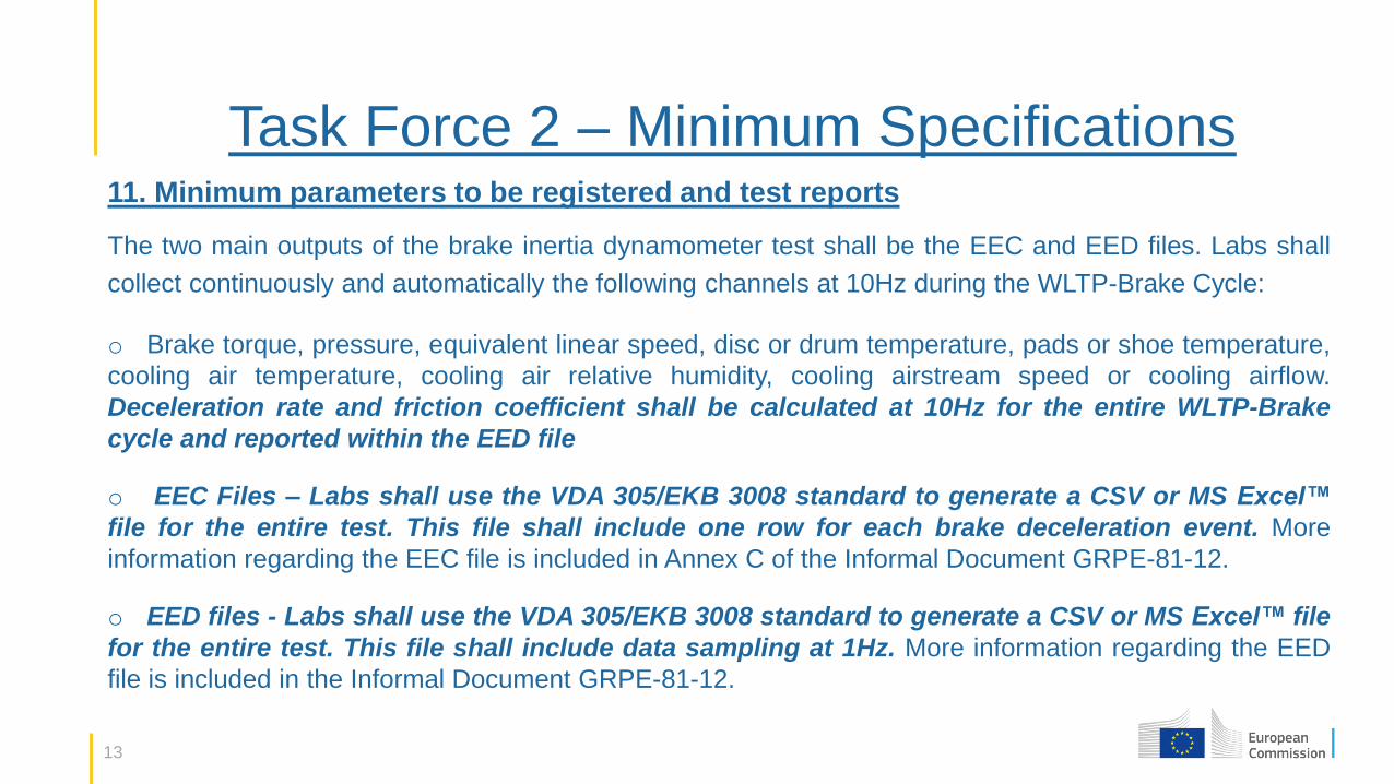
Task Force 2 – Minimum Specifications 11. Minimum parameters to be registered and test reports
The two main outputs of the brake inertia dynamometer test shall be the EEC and EED files. Labs shall
collect continuously and automatically the following channels at 10Hz during the WLTP-Brake Cycle:
o Brake torque, pressure, equivalent linear speed, disc or drum temperature, pads or shoe temperature,
cooling air temperature, cooling air relative humidity, cooling airstream speed or cooling airflow.
Deceleration rate and friction coefficient shall be calculated at 10Hz for the entire WLTP-Brake
cycle and reported within the EED file
o EEC Files – Labs shall use the VDA 305/EKB 3008 standard to generate a CSV or MS Excel™
file for the entire test. This file shall include one row for each brake deceleration event. More
information regarding the EEC file is included in Annex C of the Informal Document GRPE-81-12.
o EED files - Labs shall use the VDA 305/EKB 3008 standard to generate a CSV or MS Excel™ file
for the entire test. This file shall include data sampling at 1Hz. More information regarding the EED
file is included in the Informal Document GRPE-81-12.
14
Task Force 2 – Overview o AUDI (S. Gramstat), AVL (T. Mamakos, M. Arndt), BMW (K. Kolbeck, J. Von-Wild, T. Schroeder),
BREMBO (M. Federici, G. Perricone), CARB (Q. Yao, S. Yoon), CONTI (A. Reich, S. Fischer), DEKATI
(M. Moisio), DRIV (M. Morbach, C. Koelsch), FORD (R. Vogt, J. Grochowicz, M. Mathissen), GM (M.
Robere), HORIBA (G. Kanae Filler, D. Lugovyy), ITT (A. Sin, S. Ansaloni), JARI (H. Hagino), JRC (T.
Grigoratos, B. Giechaskiel), LINK-EU (A. Hortet, C. Schmidt), LINK-US (C. Agudelo, R. Vedula),
STELLANTIS (O. Bausch), TMD (P. Nyhof), TSI-EU (S. Percot), TSI-US (B. Anderson, F. Romay), TU
ILMENAU (D. Hesse)
o 35 full group meetings plus several preparation bilateral and smaller group meetings. Minutes
of the meetings, technical presentations on brake emission measurements, and other material related to
the testing specifications are available on the PMP website.
o The final output of the TF2 "PMP Brake Protocol - Testing Specifications" has been submitted at the
PMP Virtual Meeting on 15.07.2021 and can be found on the PMP's website
https://wiki.unece.org/display/trans/PMP+Web+Conference+15.07.2021
15
Thank you
© European Union 2021
Unless otherwise noted the reuse of this presentation is authorised under the CC BY 4.0 license. For any use or reproduction of elements that are not owned by the
EU, permission may need to be sought directly from the respective right holders.