Embed Size (px)
Citation preview
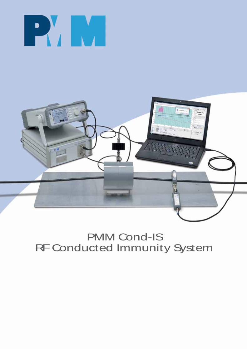
PMM Cond-ISRF Conducted Immunity System
About RF Conducted Immunity
In the global contest of EMC testing for residentialand industrial EUTs (Equipments Under Test) “RFConducted Immunity” compliance verification isdefinitely one of the easiest and less expensive tobe performed “in house”, not requiring any specialenvironment and normally involving a low powerRF Amplifier.For this reason NARDA Italy has renewed its alreadywell known PMM 6000S/10 RF Immunity Systemwith components and test management softwareto follow and even overcome latest requirementsfrom the Standard IEC/EN 61000-4-6.
PMM Modularity
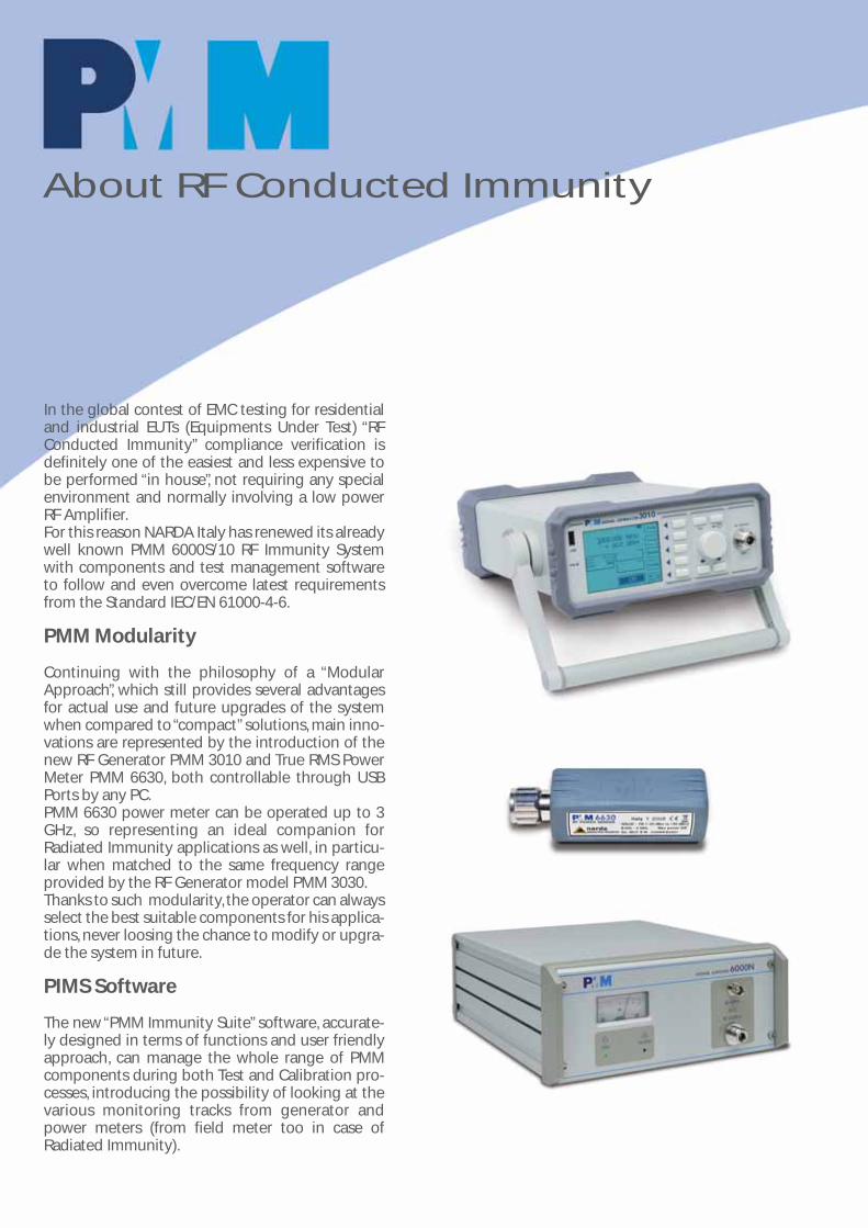
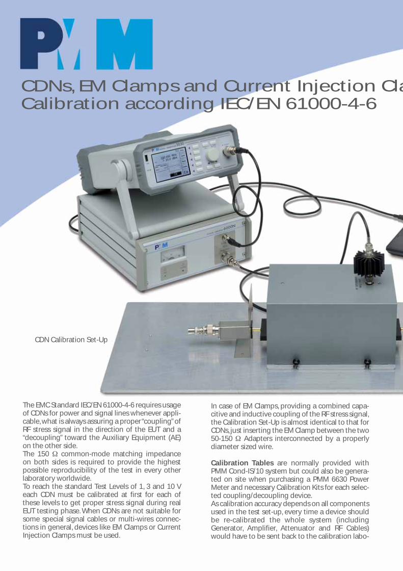
Continuing with the philosophy of a “ModularApproach”, which still provides several advantagesfor actual use and future upgrades of the systemwhen compared to “compact” solutions, main inno-vations are represented by the introduction of thenew RF Generator PMM 3010 and True RMS PowerMeter PMM 6630, both controllable through USBPorts by any PC.PMM 6630 power meter can be operated up to 3GHz, so representing an ideal companion forRadiated Immunity applications as well, in particu-lar when matched to the same frequency rangeprovided by the RF Generator model PMM 3030.Thanks to such modularity, the operator can alwaysselect the best suitable components for his applica-tions, never loosing the chance to modify or upgra-de the system in future.
PIMS Software
The new “PMM Immunity Suite” software, accurate-ly designed in terms of functions and user friendlyapproach, can manage the whole range of PMMcomponents during both Test and Calibration pro-cesses, introducing the possibility of looking at thevarious monitoring tracks from generator andpower meters (from field meter too in case ofRadiated Immunity).

PMM Cond-IS/10 System Composition
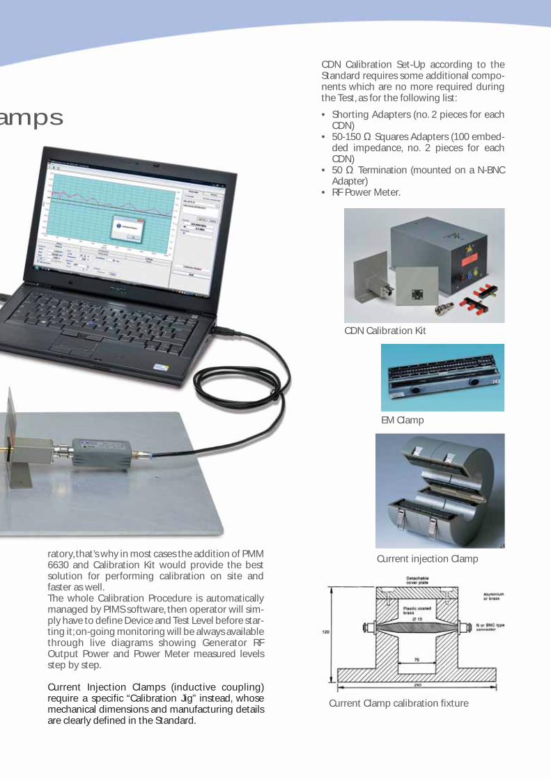
PMM Cond-IS/10 system has been designed to pro-vide all necessary components required for testingin accordance to IEC/EN 61000-4-6 with just one“package”, not losing modularity but still maintai-ning a very simple and cost effective solution.Operator can then only focus on testing, withoutworrying about collecting components and beingsure they can properly work together automaticallydriven by a specifically designed software.
PMM Cond-IS/10 system includes following stan-dard components:
• PMM 3010 Generator, 9 kHz – 1 GHz, -107 to +10dBm
• PMM 6000N Amplifier, 9 kHz – 230 MHz, 10/15 W• ATT-25W, 6 dB Attenuator, 25 W max• CDN M3-16, 3 lines 16 A each, calibrated at 1, 3
and 10 V levels• Cab-06, Cable Kit to fully connect the system• PIMS, PMM Immunity Suite software for
Windows™ OS operated PCs.
In case any different testing device should be requi-red, it would always be possible to customize thesystem accordingly.More powerful amplifiers are also available uponrequest when a “Special”Test Level over 10 V shouldbe achieved or when using an EM Clamp in conjun-ction with a Filtering Clamp; in this case the 6 dBAttenuator should be changed as well, according tothe new max power level.
As additional benefit, NARDA Italy Labs always pro-vide the selected device (CDN, EM Clamp or CurrentInjection Probe) fully calibrated at 1, 3 and 10 V stan-dard stress levels, together with the whole PMMCond-IS/10 system, i.e. including all RF cables andcomponents belonging to the real testing condi-tion.
Cond-IS/10 test set-up
CDNs, EM Clamps and Current Injection ClaCalibration according IEC/EN 61000-4-6
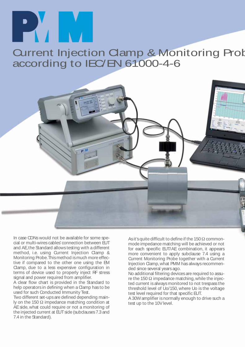
The EMC Standard IEC/EN 61000-4-6 requires usageof CDNs for power and signal lines whenever appli-cable, what is always assuring a proper “coupling”ofRF stress signal in the direction of the EUT and a“decoupling” toward the Auxiliary Equipment (AE)on the other side.The 150 Ω common-mode matching impedanceon both sides is required to provide the highestpossible reproducibility of the test in every otherlaboratory worldwide.To reach the standard Test Levels of 1, 3 and 10 Veach CDN must be calibrated at first for each ofthese levels to get proper stress signal during realEUT testing phase. When CDNs are not suitable forsome special signal cables or multi-wires connec-tions in general, devices like EM Clamps or CurrentInjection Clamps must be used.
In case of EM Clamps, providing a combined capa-citive and inductive coupling of the RF stress signal,the Calibration Set-Up is almost identical to that forCDNs, just inserting the EM Clamp between the two50-150 Ω Adapters interconnected by a properlydiameter sized wire.
Calibration Tables are normally provided withPMM Cond-IS/10 system but could also be genera-ted on site when purchasing a PMM 6630 PowerMeter and necessary Calibration Kits for each selec-ted coupling/decoupling device.As calibration accuracy depends on all componentsused in the test set-up, every time a device shouldbe re-calibrated the whole system (includingGenerator, Amplifier, Attenuator and RF Cables)would have to be sent back to the calibration labo-
CDN Calibration Set-Up
amps
CDN Calibration Set-Up according to theStandard requires some additional compo-nents which are no more required duringthe Test, as for the following list:
• Shorting Adapters (no. 2 pieces for eachCDN)
• 50-150 Ω Squares Adapters (100 embed-ded impedance, no. 2 pieces for eachCDN)
• 50 Ω Termination (mounted on a N-BNCAdapter)
• RF Power Meter.
EM Clamp
Current injection Clamp
Current Clamp calibration fixture
CDN Calibration Kit
ratory, that’s why in most cases the addition of PMM6630 and Calibration Kit would provide the bestsolution for performing calibration on site andfaster as well.The whole Calibration Procedure is automaticallymanaged by PIMS software, then operator will sim-ply have to define Device and Test Level before star-ting it; on-going monitoring will be always availablethrough live diagrams showing Generator RFOutput Power and Power Meter measured levelsstep by step.
Current Injection Clamps (inductive coupling)require a specific “Calibration Jig” instead, whosemechanical dimensions and manufacturing detailsare clearly defined in the Standard.
Current Injection Clamp & Monitoring Probaccording to IEC/EN 61000-4-6
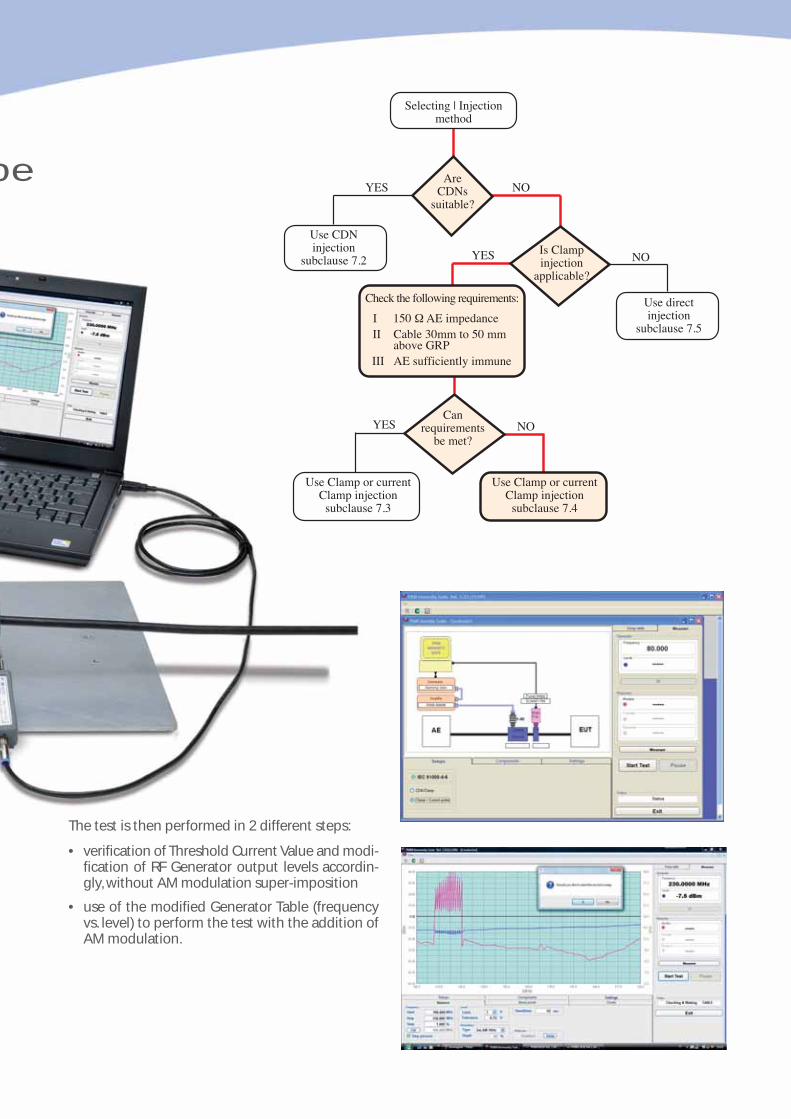
In case CDNs would not be available for some spe-cial or multi-wires cables’ connection between EUTand AE, the Standard allows testing with a differentmethod, i.e. using Current Injection Clamp &Monitoring Probe.This method is much more effec-tive if compared to the other one using the EMClamp, due to a less expensive configuration interms of device used to properly inject RF stresssignal and power required from amplifier.A clear flow chart is provided in the Standard tohelp operators in defining when a Clamp has to beused for such Conducted Immunity Test.Two different set-ups are defined depending main-ly on the 150 Ω impedance matching condition atAE side, what could require or not a monitoring ofthe injected current at EUT side (subclauses 7.3 and7.4 in the Standard).
As it’s quite difficult to define if the 150 Ω common-mode impedance matching will be achieved or notfor each specific EUT/AE combination, it appearsmore convenient to apply subclause 7.4 using aCurrent Monitoring Probe together with a CurrentInjection Clamp, what PMM has always recommen-ded since several years ago.No additional filtering devices are required to assu-re the 150 Ω impedance matching, while the injec-ted current is always monitored to not trespass thethreshold level of Uo/150, where Uo is the voltagetest level required for that specific EUT.A 30W amplifier is normally enough to drive such atest up to the 10V level.
be
The test is then performed in 2 different steps:
• verification of Threshold Current Value and modi-fication of RF Generator output levels accordin-gly, without AM modulation super-imposition
• use of the modified Generator Table (frequencyvs. level) to perform the test with the addition ofAM modulation.
Selecting | Injectionmethod
AreCDNs
suitable?
Use CDNinjection
subclause 7.2Is Clampinjection
applicable?
Use directinjection
subclause 7.5
Check the following requirements:
150 Ω AE impedanceCable 30mm to 50 mmabove GRPAE sufficiently immune
III
III
Canrequirements
be met?
Use Clamp or currentClamp injection
subclause 7.3
Use Clamp or currentClamp injection
subclause 7.4
YES NO
YES NO
YES NO

“PMM Immunity Suite” Software
• A completeReport is auto-matically gene-rated during thetest, includinginformationaboutCompany,Operator, EUTandEnvironmentalConditions, aswell as alldetails of set-tings used forthe scan andEvent Logs attime of failuresidentified bythe operator.
PMM has developed a suite of utilities specificallydesigned for EMC Immunity applications, capableof driving all necessary operations for bothCalibration and Testing with several devices (CDNs,EM Clamps, Current Injection Clamps and othersused for Radiated Immunity as well) .
The software is user friendly and provides a reallyergonomic configuration which comfortably drivesthe operator through the various steps, from defini-tion and selection of HW components to settings ofrequired parameters and finally starting the testwith “just one button”.Program window has been designed for omni-comprehensive overview of each specific testbeing performed, so that operator can easily con-trol all details with a quick glance.A graphical scheme of the test set-up clearlyreminds about proper physical connections betwe-en components, which could slightly differ betwe-en Tests and Devices’ Calibration.In the right portion of the screen two different tagsallow simple selection of Table Creation (i.e. calibra-tion) or Test Execution, providing all details aboutGenerator and Power Meter status.At window’s bottom some other tags provide intui-tive subsequent steps for setting about various Set-ups, system Components and Testing parameters.
On top of everything, testing and calibration proce-dures are always updated to state of the art requi-rements of reference Standards.
Same PIMS suite is also designed for driving RadiatedImmunity Tests according to IEC/EN 61000-4-3 in bothSemi-Anechoic Chambers or TEM/GTEM Cells, includingcalibration of radiated field up to 16 points in a grid ofField Uniformity assurance, but this is just for general info,as beyond the scope of present leaflet.So please refer to specific separate documentation for fur-ther details.
Graphical traces provide real time monitoring ofGenerator Output and Power Meter readings.

Several auxiliary functions for Debugging are also available:
• Pause during the frequency scan at EUT failures and Manual Adjustment of bothFrequency and Level to identify threshold of susceptibility.
• Break Points definition to momenta-rily stop the test at some frequenciesfor any reason.
• Multi-Scan Table to perform test onlyon most critical frequency’s segments andsave time during debugging phase.
• Automatic Fill-Up Table by line-ar interpolationbetween arbitraryGenerator OutputLevels defined bythe operator togenerate “customstress profiles”.
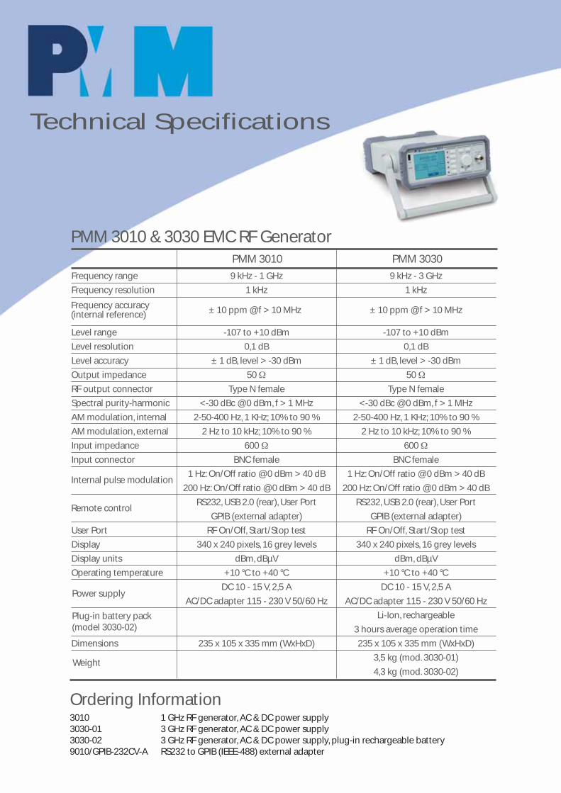
Frequency range 9 kHz - 1 GHz 9 kHz - 3 GHz
Frequency resolution 1 kHz 1 kHz
Level range -107 to +10 dBm -107 to +10 dBm
Level resolution 0,1 dB 0,1 dB
Level accuracy ± 1 dB, level > -30 dBm ± 1 dB, level > -30 dBm
Output impedance 50 Ω 50 Ω
RF output connector Type N female Type N female
Spectral purity-harmonic <-30 dBc @ 0 dBm, f > 1 MHz <-30 dBc @ 0 dBm, f > 1 MHz
AM modulation, internal 2-50-400 Hz, 1 KHz; 10% to 90 % 2-50-400 Hz, 1 KHz; 10% to 90 %
AM modulation, external 2 Hz to 10 kHz; 10% to 90 % 2 Hz to 10 kHz; 10% to 90 %
Input impedance 600 Ω 600 Ω
Input connector BNC female BNC female
1 Hz: On/Off ratio @ 0 dBm > 40 dB 1 Hz: On/Off ratio @ 0 dBm > 40 dB
200 Hz: On/Off ratio @ 0 dBm > 40 dB 200 Hz: On/Off ratio @ 0 dBm > 40 dB
RS232, USB 2.0 (rear), User Port RS232, USB 2.0 (rear), User Port
GPIB (external adapter) GPIB (external adapter)
User Port RF On/Off, Start/Stop test RF On/Off, Start/Stop test
Display 340 x 240 pixels, 16 grey levels 340 x 240 pixels, 16 grey levels
Display units dBm, dBµV dBm, dBµV
Operating temperature +10 °C to +40 °C +10 °C to +40 °C
DC 10 - 15 V, 2,5 A DC 10 - 15 V, 2,5 A
AC/DC adapter 115 - 230 V 50/60 Hz AC/DC adapter 115 - 230 V 50/60 Hz
Li-Ion, rechargeable
3 hours average operation time
Dimensions 235 x 105 x 335 mm (WxHxD) 235 x 105 x 335 mm (WxHxD)
3,5 kg (mod. 3030-01)
4,3 kg (mod. 3030-02)
PMM 3010 & 3030 EMC RF Generator
3010 1 GHz RF generator, AC & DC power supply3030-01 3 GHz RF generator, AC & DC power supply3030-02 3 GHz RF generator, AC & DC power supply, plug-in rechargeable battery9010/GPIB-232CV-A RS232 to GPIB (IEEE-488) external adapter
PMM 3010 PMM 3030
Ordering Information
Frequency accuracy(internal reference) ± 10 ppm @ f > 10 MHz ± 10 ppm @ f > 10 MHz
Internal pulse modulation
Power supply
Weight
Remote control
Plug-in battery pack(model 3030-02)
Technical Specifications
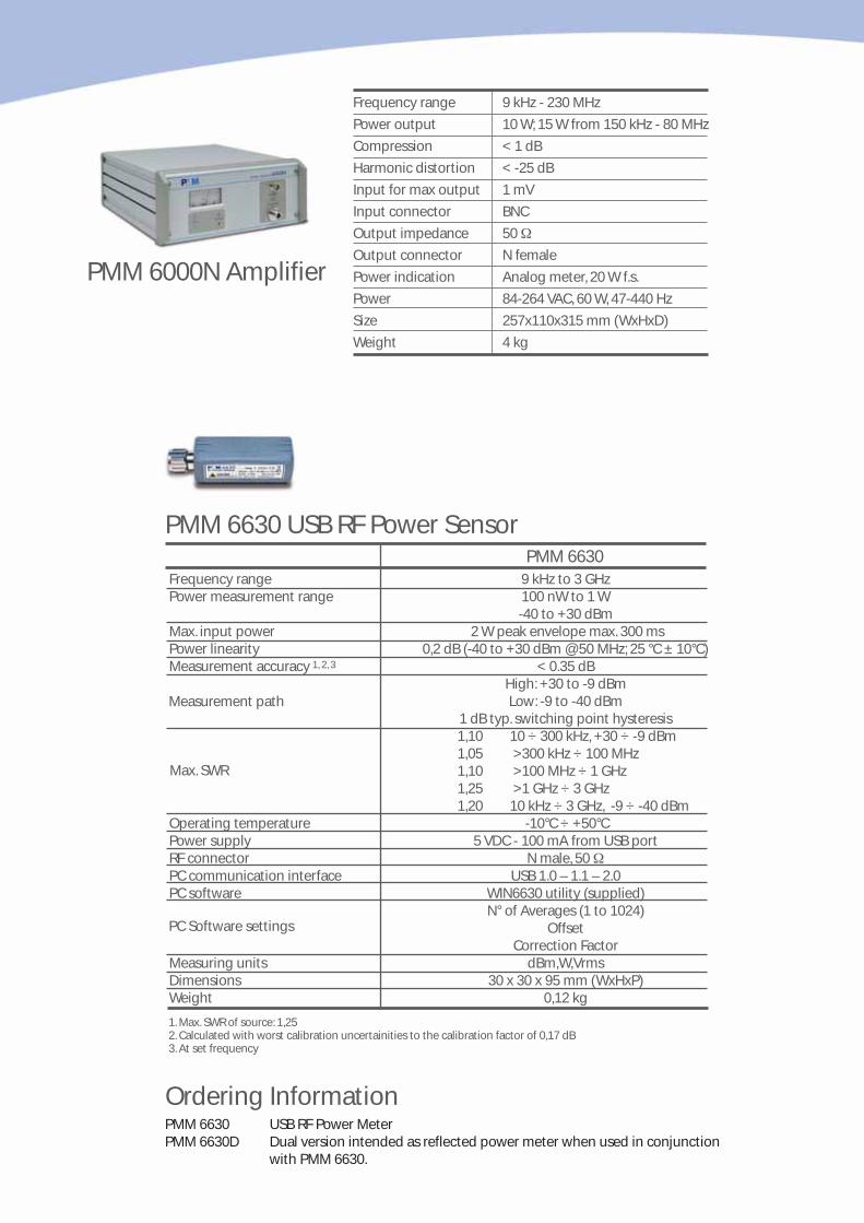
Frequency range 9 kHz - 230 MHz
Power output 10 W; 15 W from 150 kHz - 80 MHz
Compression < 1 dB
Harmonic distortion < -25 dB
Input for max output 1 mV
Input connector BNC
Output impedance 50 Ω
Output connector N female
Power indication Analog meter, 20 W f.s.
Power 84-264 VAC, 60 W, 47-440 Hz
Size 257x110x315 mm (WxHxD)
Weight 4 kg
PMM 6000N Amplifier
PMM 6630 USB RF Power Sensor
Frequency range 9 kHz to 3 GHzPower measurement range 100 nW to 1 W
-40 to +30 dBmMax. input power 2 W peak envelope max. 300 msPower linearity 0,2 dB (-40 to +30 dBm @ 50 MHz; 25 °C ± 10°C)Measurement accuracy < 0.35 dB
High: +30 to -9 dBmLow: -9 to -40 dBm
1 dB typ. switching point hysteresis1,10 10 ÷ 300 kHz, +30 ÷ -9 dBm1,05 >300 kHz ÷ 100 MHz 1,10 >100 MHz ÷ 1 GHz 1,25 >1 GHz ÷ 3 GHz 1,20 10 kHz ÷ 3 GHz, -9 ÷ -40 dBm
Operating temperature -10°C ÷ +50°CPower supply 5 VDC - 100 mA from USB portRF connector N male, 50 ΩPC communication interface USB 1.0 – 1.1 – 2.0PC software WIN6630 utility (supplied)
N° of Averages (1 to 1024)Offset
Correction FactorMeasuring units dBm,W,VrmsDimensions 30 x 30 x 95 mm (WxHxP)Weight 0,12 kg
1, 2, 3
Max. SWR
Measurement path
1. Max. SWR of source: 1,252. Calculated with worst calibration uncertainities to the calibration factor of 0,17 dB3. At set frequency
PC Software settings
PMM 6630 USB RF Power MeterPMM 6630D Dual version intended as reflected power meter when used in conjunction
with PMM 6630.
Ordering Information
PMM 6630
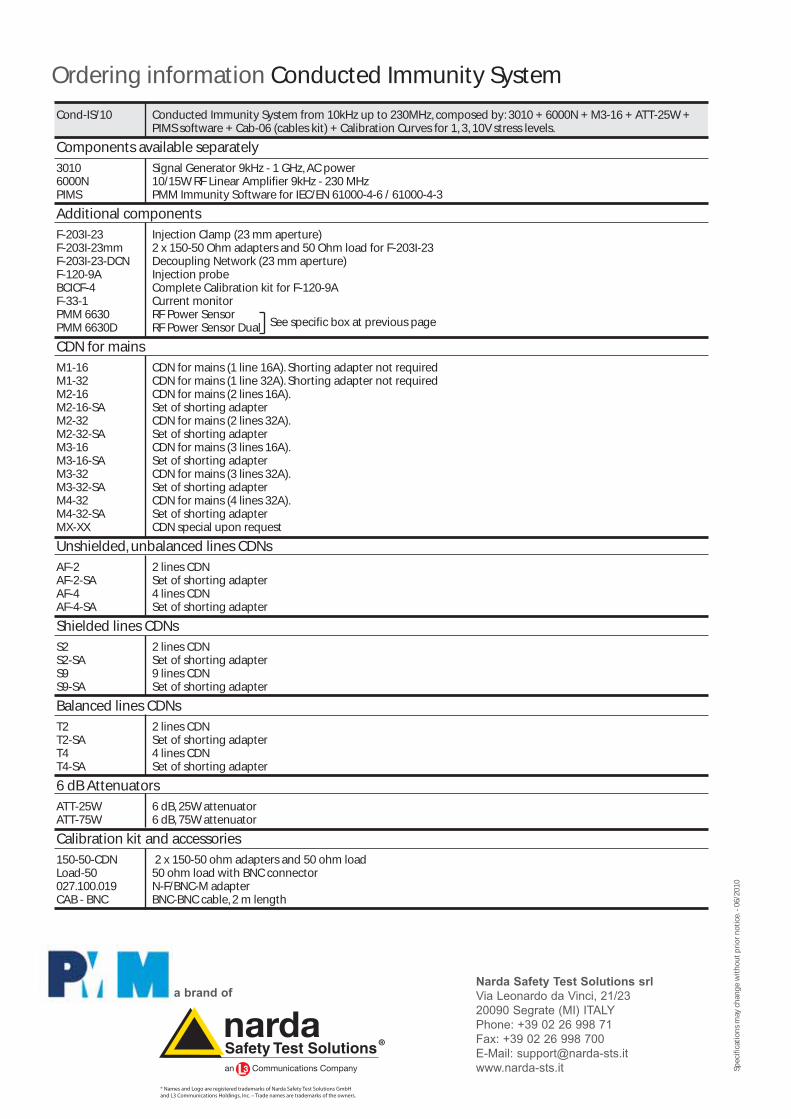
Ordering information Conducted Immunity System
Spec
ifica
tio
ns
may
ch
ang
e w
ith
ou
t p
rio
r n
oti
ce.-
06/
2010
® Names and Logo are registered trademarks of Narda Safety Test Solutions GmbHand L3 Communications Holdings, Inc. – Trade names are trademarks of the owners.
Narda Safety Test Solutions srlVia Leonardo da Vinci, 21/2320090 Segrate (MI) ITALYPhone: +39 02 26 998 71Fax: +39 02 26 998 700E-Mail: [email protected]
a brand of
Cond-IS/10 Conducted Immunity System from 10kHz up to 230MHz, composed by: 3010 + 6000N + M3-16 + ATT-25W + PIMS software + Cab-06 (cables kit) + Calibration Curves for 1, 3, 10V stress levels.
Components available separately
3010 Signal Generator 9kHz - 1 GHz, AC power6000N 10/15W RF Linear Amplifier 9kHz - 230 MHzPIMS PMM Immunity Software for IEC/EN 61000-4-6 / 61000-4-3
Additional components
F-203I-23 Injection Clamp (23 mm aperture)F-203I-23mm 2 x 150-50 Ohm adapters and 50 Ohm load for F-203I-23F-203I-23-DCN Decoupling Network (23 mm aperture)F-120-9A Injection probeBCICF-4 Complete Calibration kit for F-120-9AF-33-1 Current monitorPMM 6630 RF Power SensorPMM 6630D RF Power Sensor Dual
CDN for mains
M1-16 CDN for mains (1 line 16A). Shorting adapter not requiredM1-32 CDN for mains (1 line 32A). Shorting adapter not requiredM2-16 CDN for mains (2 lines 16A).M2-16-SA Set of shorting adapterM2-32 CDN for mains (2 lines 32A).M2-32-SA Set of shorting adapterM3-16 CDN for mains (3 lines 16A).M3-16-SA Set of shorting adapterM3-32 CDN for mains (3 lines 32A).M3-32-SA Set of shorting adapterM4-32 CDN for mains (4 lines 32A).M4-32-SA Set of shorting adapterMX-XX CDN special upon request
Unshielded, unbalanced lines CDNs
AF-2 2 lines CDN AF-2-SA Set of shorting adapter AF-4 4 lines CDN AF-4-SA Set of shorting adapter
Shielded lines CDNs
S2 2 lines CDN S2-SA Set of shorting adapter S9 9 lines CDN S9-SA Set of shorting adapter
Balanced lines CDNs
T2 2 lines CDN T2-SA Set of shorting adapter T4 4 lines CDN T4-SA Set of shorting adapter
6 dB Attenuators
ATT-25W 6 dB, 25W attenuator ATT-75W 6 dB, 75W attenuator
Calibration kit and accessories
150-50-CDN 2 x 150-50 ohm adapters and 50 ohm load Load-50 50 ohm load with BNC connector 027.100.019 N-F/BNC-M adapterCAB - BNC BNC-BNC cable, 2 m length
See specific box at previous page