Embed Size (px)
Citation preview

1 Inverter manual rev.01/19
I INVERTER PER P.M.G.
ISTRUZIONI PER L’USO E LA MANUTENZIONE
GB P.M.G. INVERTER
OPERATING AND MAINTENANCE MANUAL
F P.M.G. INVERTER
MANUEL POUR L’ENTRETIEN ET LA MANUTENTION
D P.M.G. UMRICHTER
DETRIEBS-UND WARTUNGSANLEITUNG
E P.M.G. INVERTER
INSTRUCCIONES PARA USO Y MANTENIMIENTO
P.M.G. INVERTER

2 Inverter manual rev.01/19
SOMMARIO 1. ISTRUZIONI DI SICUREZZA 1 1.1. NOTE GENERALI 2 1.2. INFORMAZIONE PER L’UTENTE 2 1.3. SPIEGAZIONE DEI SIMBOLI NEL
MANUALE 2 1.4. NOTE SPECIALI 3 2. DESCRIZIONE DEI MODELLI 4 2.1. 4kVA VERSIONE APERTA 5 2.3. CONNESSIONI 4kVA VERSIONE APERTA 7 2.4. 6kVA VERSIONE APERTA 8 2.5. CONNESSIONE 6kVA VERSIONE APERTA 10 2.7. 4kVA VERSIONE CON BOX 11 2.8. CONNESSIONI 4kVA VERSIONE CON BOX 13 2.9. 6kVA VERSIONE CON BOX 14 2.10. CONNESSIONI 6kVA VERSIONE CON BOX 16 2.11. 15kVA VERSIONE CON BOX 17 2.12. CONNESSIONI 15kVA VERSIONE CON BOX18 2.13. 20kVA VERSIONE CON BOX19 2.14. CONNESSIONI 20kVA VERSIO-NE CON BOX 20 3. CARATTERISTICHE TECNICHE 21 4. SEQUENZE DI LAVORO E ALLARMI 22 4.1.ALLARMI 22 4.2. CALCOLO DI SOVRACCARICO 23 5. NORME DI RIFERIMENTO 23 1. ISTRUZIONI DI SICUREZZA Questo manuale fornisce le informa-zioni necessarie per il corretto funzionamento degli inverter mono-fase 4-6-10-15-20kVA -230Vrms se correttamente collegati ai generatori permanenti di magneti permanenti (di seguito "PMG"). Leggere e compren-dere questo manuale prima di utiliz-zare l'apparecchiatura. In caso con-trario si potrebbero causare lesioni personali o danni alle apparecchiature! Più precisamente ciò deve evitare: · Pericolo derivante dall'operazione · Pericolo per l'operatore · Perdita di tempo e aumento dell'affi-dabilità e della durata delle attrez-zature Questo manuale dovrebbe essere considerato come una parte perma-nente dell'apparecchiatura e dovrebbe rimanere sempre con esso! ASSISTENZA CLIENTI Per ulteriori informazioni si prega di contattare il produttore dell'apparec-chiatura: Zanardi alternatori s.r.l. 36077 Altavilla Vicentina Vicenza – Italy Via Dei Laghi 48/B tel.+39 0444 370799 fax. +39 0444 370330 [email protected]
SUMMARY 1. SAFETY INSTRUCTIONS 1 1.1. GENERAL NOTES 2 1.2. USER’S INFORMATION 2 1.3. EXPLANATION OF THE SYMBOLS ON THIS MANUAL 2 1.4. SPECIAL NOTES 3 2. DESCRIPTION OF MODELS 4 2.1. 4kVA OPEN VERSION 5 2.3. CONNECTIONS 4kVA OPEN VER-SION 7 2.4. 6kVA OPEN VERSION 8 2.5. CONNECTIONS 6kVA OPEN VER-SION 10 2.7. 4kVA BOX VERSION 11 2.8. CONNECTIONS 4kVA BOX VERSION 13 2.9. 6kVA BOX VERSION 14 2.10. CONNECTIONS 6kVA BOX VERSION 16 2.11. 15kVA BOX VERSION 17 2.12. CONNECTIONS 15kVA BOX VER-SIONS 18 2.13. 20kVA BOX VERSION 19 2.14. CONNECTIONS 20kVA BOX VER-SIONS 20 3. SPECIFICATIONS 21 4. WORKING SEQUENCE AND ALARMS 22 4.1.ALARMS 22 4.2. CALCULATION OF OVERLOAD 23 5. APPLICABLE STANDARD 23 1. SAFETY INSTRUCTIONS This manual gives the necessary infor-mation for operating correctly the 4-6-10-15-20kVA -230Vrms single phase in-verters when correctly connected to the proper Permanent Magnet Generators (hereinafter referred as “PMGs”). Read and understand this manual before op-erating the equipment. Failure to do so could result in personal injuries or equipment damage! More precisely this shall avoid: ·Danger arising from the operation ·Danger to the operator ·Losses of time and increases of equip-ment reliability and durability This manual should be considered as a permanent part of the equipment and should remain always with it! CUSTOMER SERVICE For further information please contact the manufacturer of the equipment: Zanardi alternatori s.r.l. 36077 Altavilla Vicentina Vicenza – Italy Via Dei Laghi 48/B tel.+39 0444 370799 fax. +39 0444 370330 [email protected]
3 Inverter manual rev.01/19
RESUMEN 1. INSTRUCCIONES DE SEGURIDAD 1 1.1. NOTAS GENERALES 2 1.2. INFORMACIÓN PARA EL USUARIO 2 1.3. EXPLICACIÓN DE SÍMBOLOS EN MANUAL 2 1.4. NOTAS ESPECIALES 3 2. DESCRIPCIÓN DE LOS MODELOS 4 2.1. VERSIÓN ABIERTA 4kVA 5 2.3. CONEXIONES VERSIÓN 4kVA ABIERTO 7 2.4. VERSIÓN ABIERTA 6kVA 8 2.5. CONEXIÓN VERSIÓN 6 kVA ABIERTO 10 2.7. VERSIÓN DE 4KVA CON CAJA 11 2.8. CONEXIONES VERSIÓN 4kVA CON CAJA 13 2.9. VERSIÓN DE 6KVA CON CAJA 14 02:10. CONEXIONES VERSIÓN DE 6KVA CON CAJA 16 02:11. VERSIÓN DE 15KVA CON CAJA 17 02:12. CONEXIONES VERSIÓN 15kVA CON CAJA18 2.13. VERSIÓN DE 20KVA CON CAJA19 2.14. CONEXIONES VERSIÓN DE 20kVA CON CAJA 20 3. CARACTERÍSTICAS TÉCNICAS 21 4. SECUENCIAS DE TRABAJO Y ALARMAS 22 4.1.ALARMAS 22 4.2. CÁLCULO DE SOBRECARGA 23 5. NORMAS DE REFERENCIA 23
1. INSTRUCCIONES DE SEGURIDAD Este manual brinda la información necesaria para operar correctamente los inverter monofásicos 230Vrms de 4-6-10-15-20kVA cuando están conectados correctamente a los generadores de imanes permanentes adecuados (identificados como "PMG’s"). Leer y comprender este manual antes de operar el equipo. No hacerlo podría resultar en lesiones personales o daños al equipo! Más precisamente esto evitará: · Peligro derivado de la operación · Peligro para el operador · Pérdidas de tiempo y aumento de fiabilidad y durabilidad del equipo Este manual debe considerarse como parte permanente del equipo y debe permanecer siempre con ello! SERVICIO AL CLIENTE Para más información favor contactar al fabricante del equipo: Alternadores Zanardi s.r.l. 36077 Altavilla Vicentina Vicenza - Italia Via Dei Laghi 48 / B tel. + 39 0444 370799 fax. +39 0444 370330 [email protected]
ZUSAMMENFASSUNG 1.SICHERHEITSANWEISUNGEN 1 1.1. ALLGEMEINE HINWEISE 2 1.2. BENUTZERINFORMATIONEN 2 1.3. ERKLÄRUNG DER IN DIESER ANLEI-TUNG VERWENDETEN SYMBOLE 2 1.4. BESONDERE HINWEISE 3 2.BESCHREIBUNG DER MODELLE 4 2.1. OFFENE 4 kVA-AUSFÜHRUNG 5 2.3.ANSCHLÜSSE DER OFFENEN 4 kVA-AUSFÜHRUNG 7 2.4. OFFENE 6 kVA-AUSFÜHRUNG 8 2.5. ANSCHLÜSSE DER OFFENEN 6 kVA-AUSFÜHRUNG 10 2.7.GESCHLOSSENE 4 kVA- AUSFÜH-RUNG 11 2.8. ANSCHLÜSSE DER GESCHLOSSENEN 4 kVA-AUSFÜHRUNG 13 2.9. GESCHLOSSENE 6 kVA-AUSFÜHRUNG 14 2.10. ANSCHLÜSSE DER GES-CHLOSSENEN 6 kVA-AUSFÜHRUNG 16 2.11. GESCHLOSSENE 15 kVA-AUSFÜHRUNG 17 2.12. ANSCHLÜSSE DER GES-CHLOSSENEN 15 kVA-AUSFÜHRUNG 18 2.13. GESCHLOSSENE 20 kVA-AUSFÜHRUNG 19 2.14. ANSCHLÜSSE DER GECLOSSENEN 20 kVA-AUSFÜHRUNG 20 3. TECHNISCHE DATEN 21 4. BETRIEBSABLAUF UND ALARME 22 4.1. ALARME 22 4.2. BERECHNUNG DER ÜBERLAST 23 5. GELTENDE NORM 23 1. SICHERHEITSANWEISUNGEN Diese Anleitung stellt die notwendigen Informationen für den korrekten Betrieb der 4-6-10-15-20 kVA - 230 Veff-Umrichter bei richtigem Anschluss an die entsprechenden Dauermagnetgenerator-en bereit (nachfolgend als „PMGs“ bez-eichnet). Diese Anleitung muss vor dem Betrieb der Anlage gelesen und verstand-en werden. Eine Nichtbeachtung dieser Anweisung kann zu Verletzungen oder Geräteschäden führen! Insbesondere soll Folgendes vermieden werden: · Aus dem Betrieb resultierende Gefahren · Gefährdung des Bedieners · Zeitverluste und Verringerung der Zuver-lässigkeit und Lebensdauer der Geräte. Diese Anleitung ist als fester Bestandteil der Anlage zu betrachten und muss sich stets bei der Anlage befinden! KUNDENDIENST Für weitere Informationen wenden Sie sich bitte an den Hersteller der Anlage: Zanardi alternatori s.r.l. 36077 Altavilla Vicentina Vicenza – Italien Via Dei Laghi 48/B Tel. +39 0444 370799 Fax +39 0444 370330 [email protected]

4 Inverter manual rev.01/19
1.1 NOTE GENERALI Tutte le informazioni contenute in questa pubblicazione si basano sulle informazioni più recenti sul prodotto disponibili al momento dell'approva-zione per la stampa. Zanardi alternatori si riserva il diritto di apportare modifiche in qualsiasi momento senza preavviso e senza incorrere in alcun obbligo. Le illustrazioni possono variare. Nessuna parte di questa pubblica-zione può essere riprodotta senza autorizzazione scritta. Questo manuale dovrebbe essere considerato una parte permanente del prodotto e dovrebbe rimanere con esso se è rivenduto. VERIFICA ALLA CONSEGNA Alla consegna del generatore controllare con la bolla di accompagnamento che non ci siano danni o parti mancanti; nel caso informare immediatamente lo spedizionere, l’assicurazione, il rivenditore o la Zanardi alternatori . PRESCRIZIONI DI SICUREZZA Prima di qualsiasi intervento di pulizia, lubri-ficazione o manutenzione il motore primario a cui è collegato il generatore non deve essere in funzione, ma fermo e isolato dalle sue fonti di energia. Per fermare il generatore occorre seguire scrupolosamente la procedura di arresto del sistema di trascinamento; il generatore non è previsto di Stop/Emergenza, ma si arresta istantaneamente in relazione al sistema di arresto predisposto dall’installatore. Durante la consultazione del presente ma-nuale d’uso e manutenzione troverete alcu-ni simboli; questi hanno un preciso significa-to. SIMBOLOGIA CONVENZIONALE E SUA DEFINIZIONE IMPORTANTE Segnala al personale interessato che l’operazione descritta presenta un ri-schio che può avere come conseguenza un danno alla macchina, se non effettua-ta nel rispetto delle normative di sicurez-za. ACCORTEZZA Segnala al personale interessato che l’operazione descritta presenta un ri-schio che può avere come conseguenza un danno alla macchina e/o lesioni al personale stesso, se non effettuata nel rispetto delle normative di sicurezza. AVVERTIMENTO Segnala al personale interessato che l’operazione descritta presenta un ri-schio che può avere come conseguenza lesioni gravi o morte, se non effettuata nel rispetto delle normative di sicurezza. PERICOLO Segnala al personale interessato che l’operazione descritta presenta un ri-schio immediato che ha come conse-guenza lesioni gravi o morte, se non
1.1 GENERAL NOTES All information in this publication is based on the latest product information available at the time of approval for printing. Zanardi alternatori reserves the right to make changes at any time without notice and without incurring any obliga-tion. Illustrations may vary. No part of this publication may be reproduced without written permission. This manual should be considered a permanent part of the product and should remain with it if it is resold.
INSPECTION ON DELIVERY When the alternator is delivered, check that unit conforms with the delivery note and en-sure that there are no damaged or defective parts; should there be any, please inform the forwarding agent, the insurance company, the seller or Zanardi alternatori immediately. SAFETY REQUIREMENTS Before any cleaning, lubrication or mainte-nance operation, ensure that the generator is stationary and disconnected from the power supply. When stopping the generator, ensure the compliance with the procedures for stopping the prime mover. The generator, in fact, has no Emergency Stop, but is controlled by the device arranged by the installer. Symbols having specific meanings have been used throughout this instruction and maintenance manual. CONVENTIONAL SYMBOLS AND SYMBOL DESCRIPTION IMPORTANT This symbol warns the personnel concer-ned that the described operation may cause damages to the machine if it is not carried out according to the safety stan-dards. CAUTION This symbol warns the personnel concer-ned that the described operation may cause damages to the machine and/or injures to the personnel if it is not carried out according to the safety standards. WARNING This symbol warns the personnel concer-ned that the described operation may cause serious injuries or death to the per-sonnel if it is not carried out according to the safety DANGER This symbol warns the personnel concer-ned that the described operation may immediately cause serious injuries or death to the personnel if it is not carried out according to the safety standards. standards.
IMPORTANTE IMPORTANT
WICHTIG
5 Inverter manual rev.01/19
VERIFICATION A LA LIVRAISON A la livraison de l’alternateur, contrôler avec le bon de livraison qu’il n’y a aucun domma-ge ou pièces manquantes; si tel est le cas, informer immédiatement l’expéditeur, l’as-sureur, le revendeur ou Zanardi alternatori . PRESCRIPTIONS DE SECURITE Avant une quelconque intervention de net-toyage, lubrification ou manutention, le mo-teur avec lequel est accouplé l’alternateur ne doit pas être en fonctionnement mais isolé de ses sources d’énergie. Pour coupé un alternateur, il faut suivre scrupuleusement la procédure d’arrêt du système d’entraînement, l’alternateur n’est pas pourvu d’arrêt d’urgence, mais il s’arrête instantanément en fonction du sy-stème d’arrêt prévu par l’installateur. Pendant la consultation du présent manuel d’instruction et de mantenance, vous trou-verez quelques symboles; ces ont une précis signification. SIMBOLIQUE CONVENTIONNEL ET DEFINITION IMPORTANT Signe au personnel interessé que l’ope-ration décrite presente, une risque qu’il peut avoir comme conséquence une domage au la machine, si n’effectué pas dans le respect des normes de securité. ADRESSE Signe au personnel interessé que l’ope-ration décrite presente, une risque qu’il peut avoir comme conséquence une domage au la machine et/ou lésiones graves au personnel même, si n’effectué pas dans le respect des normes de secu-rité. AVVERTISSEMENT Signe au personnel intéressé que l'exécution décrite présente une risque qu'il peut avoir comme consèquence une domage ou lésiones graves ou mort, si n’effectué pas dans le respect des normes de securité. DANGER Signe au personnel intéressé que l'exécution décrite présente une risque immédiat qu'il a comme consèquence une domage ou lésiones graves ou mort, si n’effectué pas dans le respect des normes de securité.
ALLGEMEINE HINWEISE Alle Angaben in dieser Anleitung basieren auf den zum Zeitpunkt der Druckfreigabe aktu-ellen Produktinformationen. Zanardi alternatori behält sich das Recht vor, jederzeit ohne Vorankündigung und ohne ir-gendwelche Verpflichtungen Änderungen vorzunehmen. Abbildungen können abweichen. Kein Teil dieser Anleitung darf ohne schriftliche Genehmigung vervielfältigt werden. Diese Anleitung ist als fester Bestandteil des Produkts zu betrachten und muss beim Weiter-verkauf mitgeliefert werden. ÜBERPRÜFUNG BEI LIEFERUNG Bei Lieferung des Generators ist anhand des Lieferscheins dieser auf Schäden, bzw. auf fe-hlende Teile hin zu überprüfen; in diesem Falle sind der Spediteur, die Versicherung, der Wieder-verkäufer oder Zanardi alternatori umgehend darüber zu informieren. SICHERHEITS VORSCHRIFTEN Vor jedem Eingriff für Reinigung, Schmierung oder Wartung, muß der Hauptmotor, an den der Generator angeschlossen ist, außer Be-trieb gesetzt werden; er muß stillstehen und von seinen Energiequellen isoliert werden. Um dem Generator zu stoppen, ist es erforder-lich genauestens das Abstell-verfahren für das Zugsystem einzuhalten; der Generator ist nicht mit einem Sicherheits-abschalter (“NOTAUS”) versehen, sondern er stoppt unmittelbar in Abhängigkeit von dem Abschaltsystem, das vom Hersteller vorgesehen ist. Beim Nach-schlagen in diesem Handbuch zur Bedienung und Wartung sind hier und da einige Symbole zu finden; diese haben eine bestimmte Bedeu-tung. ÜBLICHE SYMBOLE UND SYMBOLBE-SCHREIBUNG WICHTIG Dieses Symbol weist das zuständige Personal darauf hin, dass der be-schriebene Vorgang zu Schäden an der Maschine führen kann, wenn er nicht gemäß den Sicherheitsnormen ausgeführt wird. VORSICHT Dieses Symbol weist das zuständige Personal darauf hin, dass der beschrie-bene Vorgang zu Schäden an der Ma-schine und/oder Verletzungen des Per-sonals führen kann, wenn er nicht ge-mäß den Sicherheitsnormen ausgeführt wird. WARNUNG Dieses Symbol weist das zuständige Personal darauf hin, dass der be-schriebene Vorgang zu schweren Ver-letzungen oder zum Tod des Perso-nals führen kann, wenn er nicht ge-mäß den Sicherheitsnormen ausge-führt wird. GEFAHR Dieses Symbol weist das zuständige Personal darauf hin, dass der beschrie-bene Vorgang unmittelbar zu schweren Verletzungen oder zum Tod des Perso-nals führen kann, wenn er nicht gemäß den Sicherheitsnormen ausgeführt wird.
1.1 NOTAS GENERALES Toda la información contenida en ésta publicación se basa en la última información del producto disponible en el momento de la aprobación para imprimir. Alternadores Zanardi se reserva el derecho de hacer modificaciones en cualquier momento sin previo aviso y sin incurrir en obligación alguna. Las ilustraciones pueden variar. Ninguna parte de esta publicación puede ser reproducida sin autorización escrita. Este manual debe ser considerado como parte permanente del producto y, si se revende, debe permanecer con ello. CONTROL A LA ENTREGA A la entraga del generador, controlar junto con la factura que no existan defectos o pie-zas faltantes; en caso contrario informar in-mediatamente la empresa de transportes, la compañia de seguros, el revendedor o la Zanardi alternatori. PRECAUCIONES DE SEGURIDAD Antes de cualquier tipo de operación de limpieza, lubrificación o mantenimiento, el motor primario al cual está acoplado el generador no debe estar en funcionamiento, el mismo deberá estar in-móvil y aislado de sus fuentes de energía. Para detener el generador es necesario seguir escrupolosamente los procedimientos de deten-ción del sistema de arrastre; el generador no posee un Stop/Emergencia, pués el mismo se detiene instantaneamente en función del sistema de stop preparado por el instalador. Durante la consultaciòn de el presente ma-nual uso y manutention, aquìy allì hallerà algunes simbolos; Esos ont une preciso signi-ficado. SIMBOLOGIA CONVENCIONAL Y SUAS DEFINICION IMPORTANTE Signa a el personal interesado que el ope-ration descrita presenta, une riesgo que puede hacer como consecuencia une daño a la maquina, se no efectuada en el respecto de les normatives de securidad. AGUDEZA Signa a el personal interesado que el ope-ration descrita presenta, une riesgo que puede hacer como consecuencia une daño a la maquina y/ou lésiones a el per-soanl mismo, se no efectuada en el re-specto de les normatives de securidad. ADVERTIMIENTO Señales a los personales interesado que la operación descrita introduce un riesgo que él pueda tener como lesiones o muer-tos serios de la consecuencia, si no está realizado en el respecto de lles normatives de securidad. PELIGRO Señales a los personales interesado que la operación descrita introduce un riesgo inmediato que tenga como lesiones o muertos seriosn de la consecuencia, si no está realizado en el respecto de les norma-tives de securidad.
6 Inverter manual rev.01/19
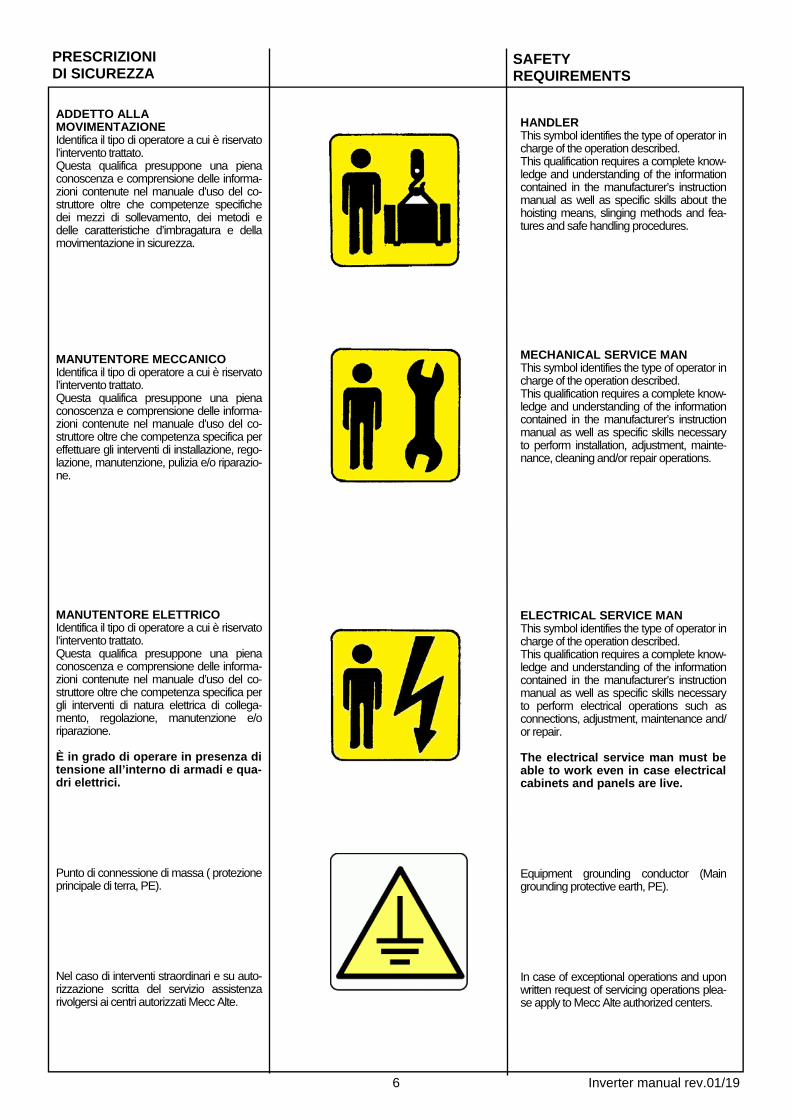
ADDETTO ALLA MOVIMENTAZIONE Identifica il tipo di operatore a cui è riservato l’intervento trattato. Questa qualifica presuppone una piena conoscenza e comprensione delle informa-zioni contenute nel manuale d’uso del co-struttore oltre che competenze specifiche dei mezzi di sollevamento, dei metodi e delle caratteristiche d’imbragatura e della movimentazione in sicurezza. MANUTENTORE MECCANICO Identifica il tipo di operatore a cui è riservato l’intervento trattato. Questa qualifica presuppone una piena conoscenza e comprensione delle informa-zioni contenute nel manuale d’uso del co-struttore oltre che competenza specifica per effettuare gli interventi di installazione, rego-lazione, manutenzione, pulizia e/o riparazio-ne. MANUTENTORE ELETTRICO Identifica il tipo di operatore a cui è riservato l’intervento trattato. Questa qualifica presuppone una piena conoscenza e comprensione delle informa-zioni contenute nel manuale d’uso del co-struttore oltre che competenza specifica per gli interventi di natura elettrica di collega-mento, regolazione, manutenzione e/o riparazione. È in grado di operare in presenza di tensione all’interno di armadi e qua-dri elettrici. Punto di connessione di massa ( protezione principale di terra, PE). Nel caso di interventi straordinari e su auto-rizzazione scritta del servizio assistenza rivolgersi ai centri autorizzati Mecc Alte.
HANDLER This symbol identifies the type of operator in charge of the operation described. This qualification requires a complete know-ledge and understanding of the information contained in the manufacturer’s instruction manual as well as specific skills about the hoisting means, slinging methods and fea-tures and safe handling procedures. MECHANICAL SERVICE MAN This symbol identifies the type of operator in charge of the operation described. This qualification requires a complete know-ledge and understanding of the information contained in the manufacturer’s instruction manual as well as specific skills necessary to perform installation, adjustment, mainte-nance, cleaning and/or repair operations. ELECTRICAL SERVICE MAN This symbol identifies the type of operator in charge of the operation described. This qualification requires a complete know-ledge and understanding of the information contained in the manufacturer’s instruction manual as well as specific skills necessary to perform electrical operations such as connections, adjustment, maintenance and/or repair. The electrical service man must be able to work even in case electrical cabinets and panels are live. Equipment grounding conductor (Main grounding protective earth, PE). In case of exceptional operations and upon written request of servicing operations plea-se apply to Mecc Alte authorized centers.
PRESCRIZIONI DI SICUREZZA
SAFETY REQUIREMENTS

7 Inverter manual rev.01/19
PRÉPOSÉ AU LA MOUVEMENTATION Identifié le type de operateur dont il est reservé l’intervention traité. Cette qualification suppose une pleine connaisance et compréhension des renseignement contenu dans le ma-nuel d’instruction du constructeur plus loin que compétences spécifiques de moyens du soulévement, des métho-des et des caractéristiques d’éligage et du mouvementation en sécurité. PRÉPOSÉ MÉCANIQUE Identifié le type de operateur dont il est reservé l’intervention traité. Cette qualification suppose une pleine connaisance et compréhension des renseignement contenu dans le ma-nuel d’instruction du constructeur plus loin que compétences spécifiques pour effectuer les interventiones d’in-stallation, regulation, manutention, nettoyage et/ou réparation. PRÉPOSÉ ÉLECTRIQUE Identifié le type de operateur dont il est reservé l’intervention traité. Cette qualification suppose une pleine connaisance et compréhension des renseignement contenu dans le ma-nuel d’instruction du constructeur plus loin que compétences spécifiquede nature électrique de liaison, regulation, manutention, et/ou réparation. Il est en degré de agir en présence de ension à l’interieur des armoires et tableaux électriques. Conducteur de mise à la terre de l'é-quipement (terre de protection de mise à la terre principale, PE). En cas des interventiones extraordi-naires et sur autorisation écrite du service et assistance s’addreser aux centres autorisés Mecc Alte.
TRANSPORTBEAUFTRAGTER Identifiziert den Personentyp, der mit dem Transport bzw. der Bewegung der Maschine beauftragt ist. Diese Qualifikation setzt eine volle Kenntnis und Verständnis der im Be-dienungshandbuch des Herstellers enthaltenen Informationen voraus, zusätzlich zu den spezifischen Kom-petenzen, was die Transport- und An-hebemittel, die Eigenschaften der Transportschlingen und der sicheren Bewegung betrifft. WARTUNGSFACHMANN MECHANIK Identifiziert den Personentyp, der mit der mechanischen Wartung beauftragt ist. Diese Qualifikation setzt eine volle Kenntnis und Verständnis der im Be-dienungshandbuch des Herstellers enthaltenen Informationen voraus, zusätzlich zu den spezifischen Kom-petenzen, was die Aufstellungs-, Ein-stellungs-, Wartungs-, Reinigungs- und/oder Reparaturarbeiten betrifft. WARTUNGSFACHMANN ELEKTRIK Identifiziert den Personentyp, der mit der elektrischen Wartung beauftragt ist. Diese Qualifikation setzt eine volle Kenntnis und Verständnis der im Be-dienungshandbuch des Herstellers enthal-tenen Informationen voraus, zusätzlich zu den spezifischen Kom-petenzen, was die Eingriffe elektri-scher Natur betrifft, wie: Anschlüsse, Einstellung, Wartung und/oder Repa-raturen. Er ist in der Lage, auch Arbeiten im Inneren von Schaltschränken und-tafeln auszuführen, wenn diese un-ter Spannung stehen. Geräteschutzleiter (Haupterdung Schutzerde, PE).
Im Fall von außergewöhnlichen Ein-griffen und auf schriftliche Bestätigung des techn. Services sich an die autori-sierten Kundendienstzentren von Mecc Alte wenden.
APLICADO A LA MOVIMENTATION Identifica el tipo de operador la cual es reservado el intervenciòn tartado. Esta calificaciòn presupone una llena conocimiento y comprensiòn des infor-maciònes contenidos en el manual para uso de el constructor de la parte de allà que competencia especifica-ciòn des medios de leventamiento, des métodos y des caracterìsticas de barrachera y de movimentaciòn en securidad. MANUTENDOR MECANICO Identifica el tipo de operador la cual es reservado el intervenciòn tartado. Esta calificaciòn presupone una llena conocimiento y comprensiòn des infor-maciònes contenidos en el manual para uso de el constructor de la parte de allà que competencia especifica-ciòn por efectuar los intervenciònes de instalaciòn, regulaciòn, manutenciòn, limpieza y/ou reparaciòn. MANUTENDOR ELÉCTRICO Identifica el tipo de operador la cual es reservado el intervenciòn tartado. Esta calificaciòn presupone una llena conocimiento y comprensiòn des infor-maciònes contenidos en el manual para uso de el constructor de la parte de allà que competencia especifica-ciòn por efectuar los intervenciònes de natura electrica de coligamiento, regu-laciòn, manutenciòn, y/ou reparaciòn. Es en grado de trabajar en presen-cia de tension a los interno des ar-marios y cuadros electricos. Conductor de puesta a tierra del equi-po (Tierra de protección principal a tierra, PE). En caso de intervenciçnes extraordi-narios y su autorizaciòn escritura du servicio assistencia revolverse a los centros autorizado Mecc Alte.
PRESCRIPTIONS DE SECURITE
SICHERHEITS VORSCRIFTEN
PRECAUCIONES DE SEGURIDAD

8 Inverter manual rev.01/19
Il sistema di inverter, per funzionare corretta-mente, richiede che la temperatura non superi i 70 ° C o gli 85 ° C (a seconda del modello) sul dissipatore di calore dell'inver-ter. Normalmente questa temperatura non viene raggiunta se le condizioni ambientali sono conformi alle specifiche del capitolo 3 e (per le versioni aperte) se la ventola ausiliaria del motore funziona correttamente. L'inverter deve essere montato in posizione verticale (pinne in posizione verticale). In caso di "versione aperta", la ventola inter-na (del generatore) deve soffiare direttamen-te contro il dissipatore di calore. Questa posizione garantisce il miglior scambio termi-co (e quindi la bassa temperatura) all'interno dell'inverter. Non collegare mai il cavo PMG all'inverter quando il motore è già in funzione: l'inverter potrebbe guastarsi. Gli antivibranti devono essere utilizzati per limitare le vibrazioni massime sull'inverter, per tutte le frequenze e situazioni. L'inverter deve essere dotato di un conduttore di messa a terra dell'ap-parecchiatura. Il conduttore neutro all'uscita dell'inver-ter può essere collegato a terra o meno a seconda del sistema di sicurezza implementato o della normativa locale seguita Se esiste un punto stella dell'alternatore e questo punto è colle-gato a massa, non è possibile collega-re il neutro dell'uscita dell'inverter a massa (e viceversa se si collega l'usci-ta neutra dell'inverter a terra, non è possibile collegare il punto stella dell'alternatore a terra) Gli inverter sono progettati per utilizzo a “isola” non per parallelo rete,e solo per un uso IP21; non utilizzare il siste-ma in caso di pioggia o neve senza gli involucri di protezione. Se il sistema cade in acqua, non cerca-re di asciugarlo e azionarlo, ma rispe-dirlo a Zanardi per i controlli di sicurez-za. Quando funziona, il sistema è una potenziale fonte di scosse elettriche; non utilizzarlo con la mano bagnata Non toccare alcuna parte degli in-verter (inclusi cavi e connettori) pri-ma di 5 minuti dopo che il motore si è fermato completamente La connessione e la manutenzione devono essere eseguite da operatori qualificati. Non è consentito modificare o sostituire alcuna parte dell'inverter. Ogni garanzia sulle parti modificate e danneggiate dall'esterno si deteriorerà. In queste condizioni Zanardi non può dare alcuna garanzia sul prodotto e alcuna responsabilità per qualsiasi tipo di incidente. Sapere come fermare il generatore rapidamente in ogni caso di problemi. Non permettere mai a nessu-no di far funzionare il generatore senza istruzioni adeguate. Non pulire l'inver-ter con sostanze corrosive.
Inverter system, in order to work cor-rectly, needs that the temperature does not exceed 70°C or 85°C (depending on the model) on the in-verter heat sink. Normally this temperature is not reached if ambient conditions are in according with specifications of Chap-ter 3 and (for open versions) if the engine auxiliary fan is correctly work-ing. Inverter must be mounted in verti-cal position (fins in vertical position). In case of “open version”, the internal (generator) fan must blow directly against the heatsink. This position guarantee the best thermal exchange (and so the low temperature) inside inverter. Never connect PMG cable to the in-verter when engine is already running: inverter could fail. Silent blocks must be used for limiting maximum vibration on the inverter, for all frequencies and situations. Inverter must be provided with an equipment-grounding conductor. Neutral conductor at the inverter’s output can be connected at ground or not depending on safety system imple-mented or local normative followed If exist a star point of alternator and this point is connected to ground, you can’t connect the inverter’s output neutral to ground (and vice-versa if you connect inverter’s output neutral to ground, you can’t connect star point of alternator to ground) The inverters are designed for “stand alone “ use and not for connect to the grid, for IP21 use only; do not operate the system in rain or snow without the protective enclosures If the system falls in water, do not try to dry it and operate it, but send it back to Zanardi for safety controls. When working, the system is a poten-tial source of electrical shocks; do not operate it with wet hand Don’t touch any part of the invert-ers (including wires and connect-ors) before 5 minutes after the en-gine has come to a complete stop Connection and maintenance must be done by qualified operators It’s not allowed to modify or replace any of part of the inverter. Any guarantee on modified and externally damaged parts will decay. In these conditions Zanardi can’t give any guarantee on the product and any responsibility for any type of accidents Know how to stop the generator quickly in every case of problems. Never permit any-one to operate the generator without proper instructions Don’t clean inverter with corrosive substances.
ACCOPPIAMENTO ELETTRICO
ELECTRICAL CONNECTIONS

9 Inverter manual rev.01/19
Um korrekt arbeiten zu können, darf die Temperatur am Kühlkörper des Umrichters 70 °C bzw. 85 °C (je nach Modell) nicht überschreiten. Normalerweise wird diese Temperatur nicht erreicht, wenn die Umge-bungsbedingungen den Angaben in Kapitel 3 entsprechen und (bei offenen Ausführun-gen) wenn das Zusatzgebläse des Motors ordnungsgemäß arbeitet. Der Umrichter muss in vertikaler Position montiert werden (Kühlrippen in vertikaler Position). Bei „offener Ausführung“ muss das interne (Generator-)Gebläse direkt auf den Kühlkör-per gerichtet sein. Diese Position garantiert den besten Wärmeaustausch (und somit eine ausreichend niedrige Temperatur) im Umrichter. Schließen Sie das DMG-Kabel niemals an den Umrichter an, wenn der Motor bereits läuft. Der Umrichter könnte beschädigt werden. Zur Begrenzung der maximalen Vibrationen am Umrichter müs-sen für alle Frequenzen und Zustände Silentblöcke eingesetzt werden. Der Umrichter muss mit einem Geräte-schutzleiter versehen sein. Der Neutralleiter am Ausgang des Umrich-ters kann je nach implementiertem Sicher-heitssystem oder vor Ort geltender Norm geerdet werden oder nicht. Wenn ein Sternpunkt des Generators vorhanden ist und dieser Punkt an Masse angeschlos-sen ist, können Sie den Ausgang des Umrichters nicht erden (und umgekehrt, wenn Sie den Ausgang des Umrichters an Masse anschließen, können Sie den Sternpunkt des Generators nicht erden). Die Umrichter sind für den "stand-alone" Gebrauch konzipiert und nicht für den Netzanschluss, für den Einsatz mit Schutz-art IP21 ausgelegt; ohne Schutzgehäuse darf das System nicht bei Regen oder Schnee betrieben werden. Wenn das Sys-tem ins Wasser fällt, versuchen Sie nicht, es zu trocknen und in Betrieb zu nehmen, sondern schicken Sie es zwecks Sicher-heitskontrollen an Zanardi zurück. Wäh-rend des Betriebs ist das System eine potenzielle Quelle von Stromschlägen; bedienen Sie das System nie mit nassen Händen. Berühren Sie Teile der Umrichter (einschließlich Kabel und Anschlüsse) erst nach 5 Minuten, nachdem der Mo-tor zum Stillstand gekommen ist. Der Anschluss und die Wartung müssen von qualifiziertem Personal durchgeführt werden. Es ist nicht zulässig, Teile des Umrichters zu verändern oder zu erset-zen. Jede Garantie auf veränderte und äußerlich beschädigte Teile erlischt. Unter diesen Bedingungen kann Zanardi keine Garantie für das Produkt gewähren und keine Haftung für Unfälle jeglicher Art übernehmen. Bei jeder Art von Problemen müssen Sie in der Lage sein, den Genera-tor umgehend zu stoppen. Lassen Sie niemals zu, dass der Generator von ir-gendjemandem ohne entsprechende An-weisungen bedient wird. Reinigen Sie den Umrichter nicht mit korrosiven Substan-zen.
El sistema inverter, para funcionar correctamente, requiere que la temperatura no supere los 70 ° C o 85 ° C (dependiendo del modelo) en el disipador de calor del inverter. Normalmente esta temperatura no se alcanza si las condiciones ambientales cumplen con las especificaciones del capítulo 3 y (para versiones abiertas) si el ventilador auxiliar del motor funciona correctamente. El inverter debe estar montado en posición vertical (aletas en posición vertical). En caso de "versión abierta", el ventilador interno (del generador) debe soplar directamente contra el disipador de calor. Ésta posición garantiza el mejor intercambio térmico (y por tanto, la baja temperatura) en el interior del inverter. Nunca conecte el cable PMG al inverter cuando el motor ya está en funcionamiento: el inverter podría dañarse. Se deben usar soportes antivibrantes adecuados para limitar las vibraciones máximas en el inverter, para todas las frecuencias y situaciones. El inverter debe estar equipado con un conductor de puesta a tierra del equipo. El conductor neutro a la salida del inverter puede ser conectado a tierra o no según el sistema de seguridad implementado o de la normativa local. Si existe un punto estrella del alternador y este punto está conectado a tierra, no es posible conectar el neutro de la salida del inverter a tierra (y viceversa si se conecta la salida neutra del inverter al suelo, no es posible conectar el punto estrella del alternador al suelo). Los inverster están diseñados solo para un uso en IP21; no use el sistema en caso de lluvia o nieve sin protección adecuada. Si el sistema cae al agua, no intentar de secarlo y operarlo, enviarlo de vuelta a Zanardi para los controles de seguridad. En funcionamiento, el sistema es una fuente potencial de descarga eléctrica; no usar con manos mojadas. No tocar ninguna parte de los inverter (incluyendo cables y conectores) antes de 5 minutos luego de que el motor primario se haya detenido por completo. Conexión y mantenimiento deben ser realizados por operadores cualificados. No está permitido modificar o reemplazar cualquier parte del inverter. Cualquier garantía sobre partes modificadas y/o dañadas desde el exterior se deteriorará. En tales condiciones, Zanardi no puede dar cualquier garantía sobre el producto y ninguna responsabilidad de ningún tipo de accidente. Sepa cómo detener el generador de forma rápida y en cualquier tipo de problema. Nunca permitir a nadie que opere el generador sin instrucciones apropiadas. No limpiar el invertir con sustancias corrosivas.
RACCORDEMENT ELECTRIQUE
ELETRISCHER ANSCHLUß
CONEXION ELECTRICA

10 Inverter manual rev.01/19
4kVA and 6kVA inverter sono en-trambe disponibili in: “versione aper-ta” (senza protezione) adatto ad es-sere inserito direttamenteall’interno di un unico contenitore compreso di mo-tore alternatore e inverter. La versione “box version” adatto all’utilizzo dove non è possibile formare il Sistema dentro un unico contenitore. Per ottenere 230Vrms in usci-ta è necessario collegare un generatore e una batteria esterna da 12V. Utilizzare il cavo di ingresso in dota-zione per collegare il generatore all'in-verter, se è necessario un cavo più lungo è possibile aggiungerlo ma uti-lizzare fili di sezione trasversale da 4 mmq o più grandi. PER 4-6kVA "APERTO" Utilizzare cavi conservati in vaso (cavi di uscita da 230Vrms) per collegare l'uscita dell'inverter al carico, se è ne-cessario un cavo più lungo è possibile aggiungerlo ma utilizzare cavi di sezio-ne quadrata 4mmq o più grandi. Per collegare il cavo di terra protet-tivo all'inverter utilizzare un cavo con sezione minima di 4 mmq con terminale ad anello imbullonato a uno dei fori filettati disponibili sul dissipatore. Utilizzare una rondella dentata tra il terminale dell'anello e il dissipatore di calore per rimuove-re la vernice anodizzante del dissi-patore di calore metallico. PER "BOX" 4-6kVA Utilizzare cavi conservati in vaso (cavi di uscita da 230Vrms) per collegare l'uscita dell'inverter al carico, se è ne-cessario un cavo più lungo è possibile aggiungerlo ma utilizzare cavi di sezio-ne quadrata 4mmq o più grandi. Collegare il cavo di terra protettivo all'inverter utilizzando un cavo con sezione minima di 4 mmq; è possi-bile collegarlo alla morsettiera di uscita o alla morsettiera di ingresso o ad entrambi sulla prima posizione dei terminali come indicato sulle etichette dell'armadio.
4kVA and 6kVA inverters are available both in “open version” (without enclo-sure) suitable to be inserted directly inside a unique generator box compris-ing engine, alternator and inverter and in “box version” suitable in cases where is not possible or not useful to have a complete generator inside a single box. To obtain 230Vrms at the out-put you have to connect gen-erator and an external 12V battery. Use the enclosed input cable to connect generator with the inverter, if you need longer cable you can add it but use 4mmq or bigger cross section wires. FOR 4-6kVA “OPEN” Use potted cables (230Vrms output wires) to connect output of the inverter to the load, if you need longer cable you can add it but use 4mmq or bigger cross section wires. To connect protective ground cable to the inverter use a cable with cross section minimum 4mmq with ring terminal bolted to one of the thread-ed holes available on the heatsink. Use a toothed washer between the ring terminal and heat sink to remove anodizing paint of the metallic heatsink. FOR 4-6kVA “BOX” Use potted cables (230Vrms output wires) to connect output of the inverter to the load, if you need longer cable you can add it but use 4mmq or bigger cross section wires. Connect protective ground cable to the inverter using a cable with cross section minimum 4mmq; you can connect it at the output terminal block, or at the input terminal block or at both of them on the first posi-tion of terminals like indicated on the labels of the cabinet.
IMPORTANTE IMPORTANT
WICHTIG
DESCRIZIONE MODELLI
DESCRIPTION OF MODELS

11 Inverter manual rev.01/19
4 kVA- und 6 kVA-Umrichter sind sowohl in „offener Ausführung“ (ohne Gehäuse) für den direkten Einbau in ein spezielles Generatorgehäuse bestehend aus Motor, Generator und Umrichter als auch in „geschlossener Ausführung“ für den Fall erhältlich, wenn es nicht möglich oder nicht sinnvoll ist, dass sich ein vollständi-ger Generator in einem einzigen Gehäu-se befindet. Um 230 Veff am Ausgang zu erhalten, müssen Sie einen Ge-nerator und eine externe 12 V-Batterie anschließen. Verwenden Sie das beiliegende Ein-gangskabel, um den Generator mit dem Umrichter zu verbinden. Wenn Sie ein längeres Kabel benötigen, können Sie es nachrüsten, benutzen Sie jedoch Kabel mit einem Querschnitt von 4 mm² oder mehr. FÜR 4-6 kVA „OFFEN” WICHTIG Verwenden Sie vergossene Kabel (230 Veff-Ausgangsleitungen), um den Aus-gang des Umrichters mit der Last zu ver-binden. Wenn Sie ein längeres Kabel benötigen, können Sie es nachrüsten, benutzen Sie jedoch Kabel mit einem Querschnitt von 4 mm² oder mehr. Für den Anschluss des Schutzleiterka-bels an den Umrichter ist ein Kabel mit einem Querschnitt von mindestens 4 mm² und einem Ringkabelschuh zu verwenden, der an eine der Gewinde-bohrungen am Kühlkörper ange-schraubt wird. Verwenden Sie eine Zahnscheibe zwischen dem Ringka-belschuh und dem Kühlkörper, um die Eloxalbeschichtung des metallischen Kühlkörpers zu entfernen. FÜR 4-6 kVA „GESCHLOSSEN” Verwenden Sie vergossene Kabel (230 Veff-Ausgangsleitungen), um den Aus-gang des Umrichters mit der Last zu ver-binden. Wenn Sie ein längeres Kabel benötigen, können Sie es nachrüsten, benutzen Sie jedoch Kabel mit einem Querschnitt von 4 mm² oder mehr. Schließen Sie ein Schutzleiterkabel mit einem Querschnitt von mindestens 4 mm² an den Umrichter an; Sie können das Kabel an der Ausgangsklemme oder an der Eingangsklemme oder an beiden an der ersten Position der Klemmen anschließen, wie auf den Etiketten des Gehäuses angegeben.
Ambos inverter de 4kVA y 6kVA están disponibles en: "versión abierta" (sin protección), adecuado para ser directamente insertado dentro de un único contenedor incluyendo motor alternador e inverter. La versión "Caja" es adecuada donde no es posible armar el sistema dentro de un único contenedor.
Para obtener una salida de 230 Vrms es necesario conectar un generador y una batería externa de 12V Usar el cable de entrada suministrado para conectar el generador al inverter; si se necesita un cable más largo, siempre se puede agregar usando cable de sección transversal de 4 mmq o superior.
PARA 4-6kVA "ABIERTO" Usar cables almacenados en vaso (cables de salida de 230Vrms) para conectar la salida del inverter a la carga; si es necesario, se puede agregar cable de sección cuadrada 4 mmq o superior.
Para conectar el cable protectivo de tierra al inverter, usar un cable con una sección mínima de 4 mmq con terminal de anillo atornillado a uno de los agujeros roscados disponibles en el disipador. Usar una arandela dentada entre el terminal del anillo y el disipador de calor para eliminar la pintura anodizada del disipador de calor metálico.
PARA 4-6kVA "CAJA" Usar cables almacenados en vaso (cables salida de 230Vrms) para conectar la salida del inverter a la carga; si es necesario, agregar cable usando cable de sección cuadrada de 4 mmq o superior.
Conectar el cable protectivo de tierra al inverter usando un cable con sección mínima de 4 mmq; es posible conectarlo al bloque de terminales de salida o al bloque de terminales de entrada o a ambos en la primera posición de los terminales como se indica en las etiquetas del panel.
BESCHREIBUNG DER MODELLE
DESCRIPCIÓN DE MODELOS

12 Inverter manual rev.01/19
PER 10 kVA "BOX" Utilizzare cavi conservati in vaso (cavi di uscita da 230Vrms) per collegare l'uscita dell'inverter al carico, se è ne-cessario un cavo più lungo è possibile aggiungerlo ma utilizzare cavi di sezio-ne quadrata 4mmq o più grandi. Utilizzare il connettore di ingresso per collegare il generatore all'inverter, utilizzare un cavo con sezione trasver-sale min. 10 mmq, max.35 mmq. Collegare il cavo di terra protettivo all'inverter usando un cavo con sezio-ne minima di 10mmq; è possibile collegarlo alla morsettiera di uscita o alla morsettiera di ingresso o ad en-trambi sulla terza posizione dei termi-nali come indicato sulle etichette dell'armadio. PER 15KVA "BOX" Utilizzare il connettore di ingresso per collegare il generatore all'inverter, utiliz-zare un cavo con sezione min.10mmq, max. Utilizzare il connettore di uscita in dotazione per collegare l'uscita dell'in-verter, utilizzare un cavo con sezione trasversale min. 10 mmq, max.35 mmq. Collegare il cavo di messa a terra per l'inverter mediante un cavo con sezione minima 10mmq; è possibile collegarlo alla morsettiera di uscita o alla morset-tiera di ingresso o ad entrambi sulla terza posizione dei terminali come indi-cato sulle etichette dell'armadio. Utilizzare il connettore di comunicazione in dotazione per collegare la scheda di controllo del motore esterno e / o il di-splay remoto, utilizzare il cavo con se-zione trasversale min. 0.35mmq, max.1.5mmq (pin1 = +, pin 2 = CAN_H, pin 3 = CAN_L, pin 4 = -) PER 20KVA "BOX" Utilizzare il connettore di ingresso per collegare il generatore all'inverter, utilizzare un cavo con sezione min.16mmq, max. 35mmq. Utilizzare il cavo della batteria in dotazione per collegare la batteria esterna, se è ne-cessario un cavo più lungo è possibile aggiungerlo ma utilizzare fili della sezione trasversale da 0,35 mmq o più grandi. Utilizzare il cavo di comunicazione per collegare la batteria esterna e la comunica-zione CAN (scheda di controllo del motore e / o pannello remoto), se è necessario un cavo più lungo è possibile aggiungerlo ma utilizzare cavi di area 0,35 mmq o più gran-di. Collegare il cavo di terra protettivo all'inverter usando un cavo con sezione minima di 10mmq; è possi-bile collegarlo alla morsettiera di uscita o alla morsettiera di ingresso o ad entrambi sulla terza posizione dei terminali come indicato sulle etichette dell'armadio.
FOR 10kVA “BOX” Use potted cables (230Vrms output wires) to connect output of the inverter to the load, if you need longer cable you can add it but use 4mmq or bigger cross section wires. Use input connector to connect gener-ator with the inverter, use cable with cross section min. 10mmq, max.35mmq. Connect protective ground cable to the inverter using a cable with cross section minimum 10mmq; you can connect it at the output terminal block, or at the input termi-nal block or at both of them on the third position of terminals like indi-cated on the labels of the cabinet. FOR 15kVA “BOX” Use input connector to connect gener-ator with the inverte, use cable with cross section min.10mmq, max. Use the enclosed output connector to connect output of the inverter, use cable with cross section min. 10mmq, max.35mmq. Connect protective ground cable to the inverter using a cable with cross section minimum 10mmq; you can connect it at the output terminal block, or at the input termi-nal block or at both of them on the third position of terminals like indi-cated on the labels of the cabinet. Use the enclosed communication con-nector to connect external motor con-trol board and / or remote display, use cable with cross section min. 0.35mmq, max.1.5mmq (pin1 =+, pin 2 = CAN_H, pin 3 = CAN_L, pin 4 = -) FOR 20kVA “BOX” Use input connector to connect gener-ator with the inverte, use cable with cross section min.16mmq, max. 35mmq. Use the enclosed battery cable to con-nect external battery, if you need long-er cable you can add it but use 0.35mmq or bigger cross section wires. Use the communication cable to con-nect external battery and CAN com-munication (motor control board and / or remote panel), if you need longer cable you can add it but use 0.35mmq or bigger area wires. Connect protective ground cable to the inverter using a cable with cross section minimum 10mmq; you can connect it at the output terminal block, or at the input termi-nal block or at both of them on the third position of terminals like indi-cated on the labels of the cabinet.
DESCRIZIONE MODELLI
DESCRIPTION OF MODELS

13 Inverter manual rev.01/19
FÜR 10 kVA „GESCHLOSSEN” Verwenden Sie vergossene Kabel (230 Veff-Ausgangsleitungen), um den Ausgang des Umrichters mit der Last zu verbinden. Wenn Sie ein längeres Kabel benötigen, können Sie es nachrüsten, benutzen Sie jedoch Kabel mit einem Querschnitt von 4 mm² oder mehr. Verwenden Sie den Eingangsstecker, um den Generator mit dem Umrichter zu verbinden. Benutzen Sie Kabel mit einem Querschnitt von min. 10 mm² bis max. 35 mm². Schließen Sie ein Schutzleiterkabel mit einem Querschnitt von mindestens 10 mm² an den Umrichter an; Sie können das Kabel an der Ausgangsklemme oder an der Ein-gangsklemme oder an beiden an der drit-ten Position der Klemmen anschließen, wie auf den Etiketten des Gehäuses angege-ben. FÜR 15 kVA „GESCHLOSSEN” Verwenden Sie den Eingangsstecker, um den Generator mit dem Umrichter zu verbinden. Benutzen Sie Kabel mit einem Querschnitt von min. 10 mm² bis max. Verwenden Sie den mitgelieferten Ausgangs-stecker, um den Ausgang des Umrichters anzuschließen. Benutzen Sie Kabel mit einem Querschnitt von min. 10 mm² bis max. 35 mm². Schließen Sie ein Schutzleiterkabel mit einem Querschnitt von mindestens 10 mm² an den Umrichter an; Sie können das Kabel an der Ausgangsklemme oder an der Ein-gangsklemme oder an beiden an der drit-ten Position der Klemmen anschließen, wie auf den Etiketten des Gehäuses angege-ben. Verwenden Sie den mitgelieferten Kommuni-kationsstecker zum Anschluss der externen Motorsteuerplatine und/oder der Fernanzeige, benutzen Sie Kabel mit einem Querschnitt von min. 0,35 mm², max. 1,5 mm² (Kontakt 1 =+, Kontakt 2 = CAN_H, Kontakt 3 = CAN_L, Kontakt 4 = -). FÜR 20 kVA „GESCHLOSSEN” Verwenden Sie den Eingangsstecker, um den Generator mit dem Umrichter zu verbinden. Benutzen Sie Kabel mit einem Querschnitt von min. 16 mm² bis max. 35 mm². Verwenden Sie das mitgelieferte Batterieka-bel, um die externe Batterie anzuschließen. Wenn Sie ein längeres Kabel benötigen, kön-nen Sie es nachrüsten, benutzen Sie jedoch Kabel mit einem Querschnitt von 0,35 mm² oder mehr. Verwenden Sie das Kommunikati-onskabel, um die externe Batterie und die CAN-Kommunikation (Motorsteuerungsplatine und/oder Fernbedienungspanel) anzuschlie-ßen. Wenn Sie ein längeres Kabel benötigen, können Sie es nachrüsten, benutzen Sie je-doch Kabel mit einem Querschnitt von 0,35 mm² oder mehr. Schließen Sie ein Schutzleiterkabel mit einem Querschnitt von mindestens 10 mm² an den Umrichter an; Sie können das Kabel an der Ausgangsklemme oder an der Ein-gangsklemme oder an beiden an der drit-ten Position der Klemmen anschließen, wie auf den Etiketten des Gehäuses angege-ben.
PARA 10 kVA "CAJA" Usar cables almacenados en vaso (cables salida de 230Vrms) para conectar la salida del inverter a la carga; si es necesario, agregar cable usando cable de sección cuadrada de 4 mmq o superior. Usar el conector de entrada para conectar el generador al inverter, usar un cable con una sección transversal min. 10 mmq, max.35 mmq. Conectar el cable protectivo de tierra al inverter usando un cable con sección transversal mínima de 10 mmq; es posible conectarlo al bloque de terminales de salida o al bloque de terminales de entrada o a ambos en la tercera posición de los terminales como se indica en las etiquetas del panel. PARA 15KVA "CAJA" Usar el conector de entrada para conectar el generador al inverter; usar un cable con una sección de 10 mmq, máx. Usar el conector de salida suministrado para conectar la salida del inverter, usar un cable con sección transversal min. 10 mmq, max.35 mmq. Conectar el cable de puesta a tierra para el inverterr por medio de un cable con sección transversal mínimo 10 mmq; es posible conectarlo al bloque de terminales de salida o al bloque de terminales de entrada o ambos en la tercera posición de los terminales como se indica en las etiquetas del panel. Usar el conector de comunicación suministrado para conectar la tarjeta de control del motor externo y / o pantalla remota, usar el cable con sección transversal min. 0.35mmq, max.1.5mmq (pin1 = +, pin 2 = CAN_H, pin 3 = CAN_L, pin 4 = -) PARA 20KVA "CAJA” Usar el conector de entrada para conectar el generador al inverter, usar un cable con sección min.16mmq, máx. 35mmq. Usar el cable suministrado de la batería para conectar la batería externa; si es cecesario, agregar cable pero de sección transversal de 0,35 mmq o superior. Usar el cable de comunicación para conectar la batería externa y la comunicación CAN (tarjeta de control del motor y / o panel remoto); si es necesario, agregar cable pero de área de 0,35 mmq o superior. Conectar el cable protectivo de tierra al inverter usando un cable con sección mínima de 10 mmq; es posible conectarlo al bloque de terminales de salida o al bloque de terminales de entrada o a ambos en la tercera posición de los terminales como se indica en las etiquetas del panel.
BESCHREIBUNG DER MODELLE
DESCRIPCIÓN DE MODELOS

14 Inverter manual rev.01/19
SPECIFICATIONS
Storage temperature -20…+55°C
Operating temperature -10...+40°C
Humidity 5…85% without condensation
Altitude Max. 2000m
Sealing protection IP21
Model 4kW open 4kW box 6kW open 6kW box 10kW box 15kW box 20kW box Continuous power 4kVA 4kVA 6kVA 6kVA 10kVA 15kVA 20kvA
Input voltage line to line
3*240..450 Vrms
3*240..450 Vrms
3*240..450 Vrms
3*240..450 Vrms
3*240..450 Vrms
3*240..450 Vrms
3*240..450 Vrms
Input frequen-cy 200…600Hz 200…
600Hz 200…600Hz 200…600Hz 200..600Hz 200.600Hz 200…600Hz
Continuous current 17.5Arms 17.5Arms 26Arms 26Arms 44Arms 65Arms 87Arms Limited time power 8kVA 1s 8kVA 1s 12kVA 1s 12kVA 1s 20kVA 1s 30kVA 1s 40kVA 1s
Short circuit duration 600ms 600ms 600ms 600ms 10 sec. 10 sec. 10 sec.
Output volt-age
220...240Vrms (nominal 230Vrms)
220...240Vrms (nominal 230Vrms)
220...240Vrms (nominal 230Vrms)
220...240Vrms (nominal 230Vrms)
220...240Vrms(nominal 230Vrms)
220...240Vrms(nominal 230Vrms)
220...240Vrms (nominal 230Vrms)
Output volt-age stability
+/- 5% (resistive load step 0-100%)
+/- 5% (resistive load step 0-100%)
+/- 5% (resistive load step 0-100%)
+/- 5% (resistive load step 0-100%)
+/- 5% (resistive load step 0-100%)
+/- 5% (resistive load step 0-100%)
+/- 5% (resistive load step 0-100%)
Voltage THD (total harmon-ic distortion)
< 3% < 3% < 3% < 3% < 3% < 3% < 3%
Output fre-quency 50Hz 50Hz 50Hz 50Hz 50Hz 50Hz 50Hz Frequency variations < 1% < 1% < 1% < 1% < 1% < 1% < 1% Peak efficien-cy 97% 97% 97% 97% 97% 97% 97%
Nominal effi-ciency
95% @ full power
95% @ full power
95% @ full power
95% @ full power
95% @ full power
95% @ full power
95% @ full power
External Air velocity re-quired @ T <= 40°C
8m/s Internal 8m/s Internal Internal Internal Internal
ELECTRICAL 10kW open
10 kVA
3*240..450 Vrms
200...600Hz
44Arms
20kVA 1s.
10 sec.
220...240Vrms (nominal 230Vrms)
+/-5%(resistive load step 0-100%)
<3%
50Hz
<1%
97%
95%@full power
8m/s
MECHANICAL
Model 4kw open 4kw box 6kw open 6kw box 10kw box 15kw box
Length 232mm 326mm 277mm 326mm 502mm 502mm
Width 186mm 315mm 224mm 315mm 433mm 433mm
Depth 95mm 142mm 125mm 142mm 241mm 241mm
Weight 3.5kg 5kg 6.5kg 8kg 22kg 25kg
10kw open
320mm
225mm
140mm
10kg
20kw box
502mm
433mm
241mm
25kg

15 Inverter manual rev.01/19
CN2
CONNECTOR PIN DESCRIPTION CN1 1 – wire black Input phase U 2 – wire light blue Input phase V 3 – wire red Input phase W 4 DC_BUS+ 5 NC 6 DC_BUS-
CONNECTOR PIN DESCRIPTION
CN4 1 – wire red +12V battery
2 – wire white CAN_H
3 – wire green CAN_L
4 – wire black Battery GND
230Vrms
CN3 CN4
CN1
CN2 and CN3, only for internal use
2.9 OVERALL DIMENSIONS 4 kVA OPEN VERSION

16 Inverter manual rev.01/19
Accessories shipped together with the inverter:
Input cable
Battery cable
Communication + battery cable
T connector to put two devices on the same CAN bus communication (one device per row)
Always the same order have to be used:
The wirings included on the inverter side use a female connector with wires with this order:Pin 1 – red – +12V INV. SUPPLY Pin 2 – white- CAN_HPin 3 – green – CAN_L Pin 4 – black – 0V INV. SUPPLY Connection between cable coming from inverter and cable coming from motor control board:

17 Inverter manual rev.01/19
Accessories shipped together with the open version inverter:
Input cable
Battery cable
Communication cable
2.9 OVERALL DIMENSIONS 6 kVA OPENVERSION

18 Inverter manual rev.01/19
2.10 CONNECTIONS 4-6 kVA BOX VERSION
Accessories shipped together with the inverter:
Push in spring connector – Input from alternator
Output connector – Output of inverter*
Battery connector
Communication connector
2.9 OVERALL DIMENSIONS 4-6 kVA BOX VERSION
*= draw power only between the L1-L2 connectors. the mass terminal is not a power pick-up point

19 Inverter manual rev.01/19
2.9 OVERALL DIMENSIONS 8-10 kVA BOX VERSION
Accessories shipped together with the inverter: Communication connector
2.10 CONNECTIONS 8-10 kVA BOX VERSION
*= draw power only between the L1-L2 connectors. the mass terminal is not a power pick-up point

20 Inverter manual rev.01/19
Accessories shipped together with the inverter: Communication connector
2.9 OVERALL DIMENSIONS 15-20 kVA BOX VERSION
2.10 CONNECTIONS 15-20 kVA BOX VERSION
*= draw power only between the L1-L2 connectors. the mass terminal is not a power pick-up point

21 Inverter manual rev.01/19
Accessories shipped to-gether with the inverter:
2.9 OVERALL DIMENSIONS 15- kVA 120+120V. BOX VERSION
2.10 CONNECTIONS 15 kVA 120+120V. BOX VERSION
*= draw power only between the L1-L2-N connectors. the mass terminal (P.E.) is not a power pick-up point

22 Inverter manual rev.01/19
All inverters start generation 2 sec-onds after then internal DC bus (rectification of input three phase voltage) reached at least 340V (at this value of DC bus is not guaran-teed a stable 230V output depending on the characteristics of the alterna-tor used). Nominal DC bus voltage used is 410Vdc (there is a step down stage to control DC voltage reduc-tion), this value guarantees 230V output with any load. This means that input alternator has to guarantee 290Vrms phase to phase at the input of inverter. Not exceed 450Vrms phase to phase for input voltage in any case. Not exceed 600Hz for input voltage in any case. ALARMS Exist following alarms: Overload Load exceed limits indicated in the specifications (Chapter 3) Short circuit Short circuit at the output of inverter for more than 600ms (inverters don’t stop supply during a short circuit for 600ms) Under voltage Output voltage lower than 190Vrms for more than 2.5s (output voltage goes down because input voltage from alternator goes down) Over temperature Heatsink temperature reached maxi-mum temperature (due to high ambi-ent temperature) General error Internal error due to failure or com-munication error or synchronization error. To reset these alarms it’s necessary: Or use remote panel control Or turn off inverter that means: switch off external battery for 4kVA and 6kVA, to stop engine and wait 1m for 10-15kVA and 20kVA.
Tutti gli inverter iniziano la fase di generazione due secondi dopo che il DC bus (tensione raddrizzata dall’ingresso trifase), interno rag-giunge almeno 340 V. (a questo livello di tensione di DC bus non è garantito una uscita stabile a 230Vac. Questo dipende dalla carat-teristica e il modello dell’alternatore usato). La tensione nominale del DC bus è 410 V. ( la fase di Controllo prevede uno stage step-down per ridurre la tensione). Questo garanti-sce la tensione di 230V. In uscita con qualsiasi caico. Ciò significa che l'alternatore di ingresso deve gar-antire una tensione di fase di 290Vrms all'ingresso dell'inverter. Non superare in ogni caso 450 Vrms fase-fase per la tensione di ingresso. In ogni caso, non superare 600Hz per la tensione di ingresso. ALLARMI Esistono I seguenti allarmi: Sovraccarico Se il carico supera i limiti indicati nelle specifiche (capitolo 3) Corto circuito Cortocircuito sull'uscita dell'inverter per oltre 600 ms (gli inverter non interrompono l'alimentazione duran-te un corto circuito per 600 ms) Sotto tensione Tensione di uscita inferiore a 190 Vrms per più di 2,5 s (la tensione di uscita diminuisce perché la tensione di ingresso dell'alternatore diminu-isce) Temperatura eccessiva La temperatura del dissipatore ha raggiunto la temperatura massima (a causa della temperatura ambi-ente elevata) Errore generale Errore interno a causa di errore o errore di comunicazione o errore di sincronizzazione. Per resettare questi allarmi è neces-sario: O utilizzare il controllo del pannello remotoOppure spegnere l'inverter che significa: spegnere la batteria esterna per 4kVA e 6kVA, per spegnere il motore e attendere 1m per 10-15kVA e 20kVA.
WORKING SEQUENCE AND ALARMS
SEQUENZE DI LAVORO E ALLARMI

23 Inverter manual rev.01/19
Todos los inverter comienzan la fase de generación dos segundos después de que el bus de CC interno (voltaje rectificado de la entrada trifásica), alcance al menos 340V. (a este nivel de voltaje del bus de CC no se garantiza una salida estable a 230Vac. Esto depende de la características y modelo del alternador utilizado). La tensión nominal del bus CC es 410V. (la fase de control preve una etapa de reducción para bajar la tensión). Esto garantiza la tensión de 230V, en salida con cualquier carga. Esto significa que el alternador de entrada debe garantizar un voltaje de fase de 290Vrms en la entrada del inverter. En cualquier caso, no exceder 450Vrms fase-fase para la tensión de entrada. En cualquier caso, no exceder 600Hz para la tensión de entrada.
ALARMAS Existen las siguientes alarmas: Sobrecarga Si la carga excede los límites indicados en las especificaciones (capítulo 3) Cortocircuito Cortocircuito en la salida del inverter durante más de 600 ms (los inverter no dejan de alimentar durante un cortocircuito por 600 ms) Baja tensión Voltaje de salida inferior a 190 Vrms por más de 2.5 s (el voltaje de salida disminuye porque el voltaje de entrada del alternador disminuye) Temperatura excesiva La temperatura del disipador de calor ha alcanzado la temperatura máxima (debido a la temperatura ambiente elevada) Error general Error interno debido a error o error de comunicación o error de sincronización. Para restablecer estas alarmas, es necesario: o usar el control de panel remoto o apagar el inverter lo que significa: apagar la batería externa para 4kVA y 6kVA, y apagar el motor y esperar 1m para 10-15 kVA y 20 kVA.
Alle Umrichter beginnen mit der Stromerzeugung 2 Sekunden, nach-dem der interne DC-Bus (Gleichrichtung der dreiphasigen Ein-gangsspannung) mindestens 340 V erreicht hat (bei diesem Wert des DC-Busses ist ein stabiler 230 V-Ausgang in Abhängigkeit von den Eigenschaf-ten des verwendeten Generators nicht gewährleistet). Die verwendete Nenn-spannung des DC-Busses beträgt 410 VDC (es gibt eine Abwärtsstufe zur Steuerung der Gleichspannungsredu-zierung), dieser Wert garantiert eine Ausgangsspannung von 230 V bei jeder Last. Das bedeutet, dass der Eingangsgenerator 290 Veff zwischen den Phasen am Eingang des Umrich-ters gewährleisten muss. Bei der Eingangsspannung dürfen 450 Veff zwischen den Phasen nicht über-schritten werden. Die Eingangsspannung darf auf keinen Fall 600 Hz überschreiten. ALARME Es können folgende Alarme auftreten: Überlastung Die Last überschreitet die in den tech-nischen Daten angegebenen Grenz-werte (Kapitel 3) – Kurzschluss Kurzschluss am Ausgang des Umrich-ters für mehr als 600 ms (Umrichter unterbrechen die Stromversorgung nicht bei einem Kurzschluss mit einer Dauer von bis zu 600 ms) Unterspannung Ausgangsspannung ist für mehr als 2,5 s niedriger als 190 Veff (die Aus-gangsspannung sinkt, weil die Ein-gangsspannung des Generators sinkt) Übertemperatur Kühlkörpertemperatur hat die maxima-le Temperatur erreicht (aufgrund hoher Umgebungstemperatur) Allgemeiner Fehler Interner Fehler aufgrund einer Störung oder eines Kommunikationsfehlers oder eines Synchronisationsfehlers. Um diese Alarme zurückzusetzen, ist Folgendes erforderlich: Entweder ist das Fernbedienungspan-el zu verwenden Oder der Umrichter ist auszuschalten, das heißt: externe Batterie für 4 kVA und 6 kVA aus-schalten, um den Motor zu stoppen und 1 m für 10-15 kVA und 20 kVA warten.
BETRIEBSABLAUF UND ALARME
SECUENCIAS DE TRABAJO Y ALARMAS

24 Inverter manual rev.01/19
Type Overload Short circuit Over temperature
4kVA open I*t = 20A*s over 18.7Arms Current limited @ 50Apk for 600ms 70°C
4kVA box I*t = 20A*s over 18.7Arms Current limited @ 50Apk for 600ms 70°C
6kVA open I*t = 30A*s over 28Arms Current limited @ 70Apk for 600ms 70°C
6kVA box I*t = 30A*s over 28Arms Current limited @ 70Apk for 600ms 70°C
10kVA box I*t = 50A*s over 47Arms Current limited @ 123Apk for 600ms 85°C
15kVA box I*t = 75A*s over 66Arms Current limited @ 185Apk for 600ms 85°C
20kVA box I*t = 100A*s over 93Arms Current limited @ 246Apk for 600ms 85°C
APPLICABLE STANDARDS
Low voltage directive LVD (2006/95/EC)
Power electronics safety EN50178
EMC directive EMC (2004/108/EC)
Emission EN55022
Immunity EN61000-6-1
Harmonics EN61000-3-2 <16A; EN61000-3-12 >16A
4.2 CALCULATION OF OVERLOAD Using table above it’s possible to calculate permissible overloads for the different electrical sizes of inverters
We use a 4kVA open version inverter and we want to know permissible time to supply 6kVA without alarms: 6000/230 = 26Arms 26Arms-18.7Arms = 7.3Arms over the limit 20A*s = 7.3*t T = 2.74s = maximum time @ 6kVA
We use a 15kVA box version inverter and we want to know maximum power overload permissible in 2s: Imax = Overload rms Imax-66Arms = over the limit 75A*s = (Imax-66)*2 A*s Imax = (75+132)/2 = 103.5Arms
Overload, short circuit and over temperature have different values depending on the electrical size of the invert-er, in particular:

25 Inverter manual rev.01/19
MECC ALTE SPA via Roma, 20 - 36051 Creazzo (VI)
Tel +39 0444 396111 - Fax +39 0444 396166 e-mail : [email protected] sito web : www.meccalte.com
FAR EAST MECC ALTE (F.E.) PTE LTD
19 KIAN TECK DRIVE SINGAPORE 628836
TEL. +65 62 657122 FAX +65 62 653991
AUSTRALIA MECC ALTE ALTERNATORS PTY LTD
10 DUNCAN ROAD, PO BOX 1046 DRY CREEK, 5094 SOUTH AUSTRALIA
TEL. +61 08/83498422 FAX +61 08/83498455
FRANCE MECC ALTE INTERNATIONAL S.A.
Z.E.LA GAGNERIE 16330 ST.AMANT DE BOIXE
TEL. 0545/397562 FAX 0545/398820
CHINA MECC ALTE ALTERNATOR (HAIMEN) LTD
755 NANHAI EAST ROAD JIANGSU HAIMEN ECONOMIC DEVELOPMENT AREA
226100 PEOPLE’S REPUBLIC OF CHINA TEL: 86 513-82325758
INDIA MECC ALTE INDIA PVT LTD
PLOT No. -1, SANASWADI - TALEGAON DHAMDHERE
ROAD TALUKA : SHIRUR, DISTRICT : PUNE -
DEUTSCHLAND MECC ALTE GENERATOREN GmbH
ENSENER WEG 21 D-51149 KÖLN
TEL. 0 22 03 / 50 38 10 FAX 0 22 03 / 50 37
UNITED KINGDOM MECC ALTE U.K LTD 6 LANDS’ END WAY
OAKHAM RUTLAND LE 15 6RF TEL. 1572/771160 FAX 1572/771161
ESPAÑA MECC ALTE ESPAÑA S.A.
C/ RIO TAIBILLA, 2 POLIG. IND. LOS VALEROS
03178 BENIJOFAR (ALICANTE)
U.S.A. AND CANADA Mecc Alte Inc.
1229 Adams Drive McHenry, Il. 60051
Tel. 815-344-0530 Fax.815-344-0535
PART OF
GROUP