Embed Size (px)
Citation preview
ControllerControllerController
523 Controller
Controller
PMEC/AMECPSEP/ASEP/DSEPMSEPERC3ERC2PCON-CA/CFAPCONACON
PCON/ACON-ABUSCON-CAMSCONPSELASELSSELXSELPS-24
PS241/PS242
PMEC/AMEC PSEP/ASEP/DSEP MSEP
MSCON PSELSCON-CA ASEL SSEL XSELPCON-ABUACON-ABU
PCON-CA ACONERC2ERC3
ControllerController Controller
Controller 524
PMECAMEC
Controller
Pulse Motor
Servo Motor (24V)
Servo Motor (200V)
LinearServo Motor
PSEP ASEPDSEP
MSEP
ERC3
ERC2
PCON-CA
PCON
ACON
SCON-CA
MSCON
PSEL
ASEL
SSEL
XSEL
PS-24
PMEC 3 Position Controller for RCP3/RCP2 PMEC-C537
AMEC 3 Position Controller for RCA2/RCA/RCL AMEC-C
PSEP 3 Position Controller for RCP3/RCP2 PSEP-C / CW
ASEP 3 Position Controller for RCA2/RCA/RCL ASEP-C / CW 547
DSEP 3 Position Controller for RCD DSEP-C / CW
Position Controller for RCP4/RCP3/RCP2/RCA2/RCA/RCL, 8-axis type MSEP-C 563
ERC3 ERC3 Controller ERC3 577
ERC2 ERC2 Controller ERC2 597
PCON-CA/CFA Position Controller for RCP4 (with high output driver) /RCP3/RCP2 PCON-CA / CFA 607
PCON Position Controller for RCP3/RCP2 PCON-CY / PL / PO / SE 623
ACON Position Controller for RCA2/RCA/RCL ACON-C / CG / CY / PL / PO / SE 631
PCON-ABUSimple Absolute Unit for PCON/ACON Controller PCON / ACON-ABU 641
ACON-ABU
SCON-CA Position Controller for RCS3/RCS2 SCON-CA 643
MSCON Position Controller for RCS3/RCS2, 6-axis type MSCON-C 655
PSEL Program Controller for RCP3/RCP2 PSEL-CS 665
ASEL Program Controller for RCA2/RCA/RCL ASEL-CS 675
SSEL Program Controller for RCS3/RCS2 SSEL-CS 685
XSEL Multi-axis Program Controller for RCS3/RCS2 X-SEL-J / K / P / Q / R / S 695
PS-24 24-VDC Power Supply for ROBO Cylinder PS-241 / 242 717
MSEP
Controller
525 Controller
PMECAMEC
Controller
Pulse Motor
Servo Motor (24V)
Servo Motor (200V)
LinearServo Motor
PSEP ASEPDSEP
MSEP
ERC3
ERC2
PCON-CA
PCON
ACON
SCON-CA
MSCON
PSEL
ASEL
SSEL
XSEL
PS-24
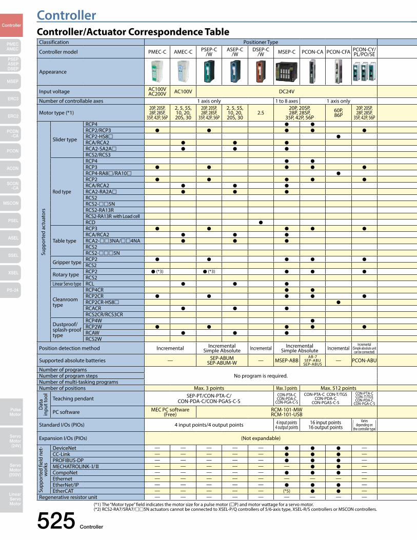
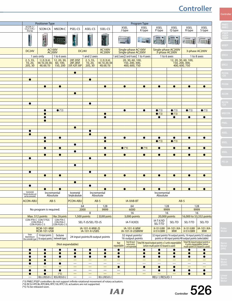
(*1) The “Motor type” field indicates the motor size for a pulse motor (P) and motor wattage for a servo motor. (*2) RCS2-RA7/SRA7/5N actuators cannot be connected to XSEL-P/Q controllers of 5/6-axis type, XSEL-R/S controllers or MSCON controllers.
Controller/Actuator Correspondence TableClassification Positioner Type Positioner Type Program Type
Controller model PMEC-C AMEC-C PSEP-C/W
ASEP-C/W
DSEP-C/W MSEP-C PCON-CA PCON-CFA PCON-CY/
PL/PO/SEACON-C/
CG/CY/PL/PO/SE
SCON-CA MSCON-C PSEL-CS ASEL-CS SSEL-CS XSELJ type
XSELK type
XSELP type
XSELQ type
XSELR type
XSELS type
Appearance
Input voltage AC100VAC200V AC100V DC24V DC24V AC100V
AC200V DC24V AC100VAC200V
Single-phase AC100VSingle-phase AC200V
Single-phase AC200V3-phase AC200V 3-phase AC200V
Number of controllable axes 1 axis only 1 to 8 axes 1 axis only 1 axis only 1 to 6 axes 1 and 2 axes 1 and 2 axes 3 and 4 axes 1 to 4 axes 1 to 6 axes 1 to 8 axes
Motor type (*1)20P, 20SP, 28P, 28SP,
35P, 42P, 56P
2, 5, 5S, 10, 20, 20S, 30
20P, 20SP, 28P, 28SP,
35P, 42P, 56P
2, 5, 5S, 10, 20, 20S, 30
2.520P, 20SP, 28P, 28SP,
35P, 42P, 56P60P, 86P
20P, 20SP, 28P, 28SP,
35P, 42P, 56P
2, 5, 5S, 10, 20, 20S, 30
12, 20, 30, 60, 100, 150, 200, 300,
400, 600, 750
12, 20, 30,60, 100,150, 200
20P, 20SP,28P, 28SP,
35P, 42P, 56P
2, 5, 5S,10, 20,20S, 30
12, 20, 30, 60,100, 150, 200, 300
400, 600, 750
20, 30, 60, 100,150, 200, 300,400, 600, 750
12, 20, 30, 60, 100,150, 200, 300,400, 600, 750
Slider type
RCP4 RCP2/RCP3 RCP2-HS8 RCA/RCA2 RCA2-SA2A RCS2/RCS3
Rod type
RCP4 RCP3 RCP4-RA8/RA10 RCP2 RCA/RCA2 RCA2-RA2A RCS2 (*2) (*2) (*2) (*2) (*2)RCS2-5N (*2) (*2)RCS2-RA13R RCS2-RA13R with Load cell RCD
Table type
RCP3 RCA/RCA2 RCA2-3NA/4NA RCS2 RCS2-5N (*2) (*2)
Gripper type RCP2 RCS2 (*4) (*4)
Rotary type RCP2 (*3) (*3) RCS2
Linear Servo type RCL
Cleanroom type
RCP4CR RCP2CR RCP2CR-HS8 RCACR RCS2CR/RCS3CR
Dustproof/splash-proof type
RCP4W RCP2W RCAW RCS2W
Position detection method Incremental IncrementalSimple Absolute Incremental Incremental
Simple Absolute IncrementalIncremental
(Simple absolute unit can be connected)
Incremental(Simple absolute unit
can be connected)Incremental
AbsoluteIncremental
Simple absoluteIncremental
AbsoluteIncremental
Absolute
Supported absolute batteries — SEP-ABUMSEP-ABUM-W — MSEP-ABB
AB-7SEP-ABU
SEP-ABUS— PCON-ABU ACON-ABU AB-5 PCON-ABU AB-5 IA-XAB-BT AB-5
Number of programsNo program is required. No program is required.
64 128 64 128 128Number of program steps 2000 9999 6000 9999 9999Number of multi-tasking programs 8 16 16 16Number of positions Max. 3 points Max. 3 points Max. 512 points Max. 512 points Max. 256 points 1,500 points 20,000 points 3,000 points 20,000 points 16,000 to 53,332 points
Teaching pendant SEP-PT/CON-PTA-C/CON-PDA-C/CON-PGAS-C-S
CON-PTA-CCON-PDA-C
CON-PGA-C-S
CON-PTA-C CON-T/TGSCON-PDA-C
CON-PGAS-C-S
CON-PTA-CCON-T/TGSCON-PDA-C
CON-PGA-C-S
CON-PTA-C CON-T/TGSCON-PDA-C
CON-PGAS-C-S
CON-PTA-CCON-PDA-C
CON-PGAS-C-SSEL-T-JS/SEL-TD-JS IA-T-X(XD) IA-T-X/XD
SEL-T/TD SEL-TD SEL-T/TD SEL-TD
PC software MEC PC software(Free)
RCM-101-MWRCM-101-USB
RCM-101-MWRCM-101-USB
IA-101-X-MW-JSIA-101-X-USBS
IA-101-X-MWIA-101-X-USBMW
IA-101-X-MWIA-101-X-USBMW
IA-101-XA-MW
IA-101-X-MWIA-101-X-USBMW
IA-101-XA-MW
Standard I/Os (PIOs) 4 input points/4 output points 4 input points4 output points
16 input points16 output points
Varies depending on (the controller type) Varies
depending on (the controller type) 16 input points16 output points
Exclusive (network type) 24 input points/8 output points 32 input points/16 output points
32 input points/16 output points, 16 input points/32 output points or 48 input points/48 output points (selectable)
Expansion I/Os (PIOs) (Not expandable) (Not expandable) Not expandable
Total 48 input/output points
1 unit expandable Total 96 input/output points x 3 units expandable
(when multi-point I/O board is used) Total 96 input/output points x
4 units expandable (when multi-point I/O board is used)
DeviceNet — — — — — — CC-Link — — — — — — PROFIBUS-DP — — — — — — MECHATROLINK- I/II — — — — — — — — — — — — — — — — —CompoNet — — — — — — — — — — — — — — —Ethernet — — — — — — — — — — — — — — — — —EtherNet/IP — — — — — — — — — — — EtherCAT — — — — — (*5) — (*5) — — — — — — —
Regenerative resistor unit — — — — — — — — — — REU-2/RESUD-2 RESU/RESUD-2 — — REU-2/RESUD-2 REU-1/RESUD-1
Supp
orte
d ac
tuat
ors
Dat
a in
put t
ool
Supp
orte
d fie
ld n
et-
wor
ks
Controller
Controller 526
PMECAMEC
Controller
Pulse Motor
Servo Motor (24V)
Servo Motor (200V)
LinearServo Motor
PSEP ASEPDSEP
MSEP
ERC3
ERC2
PCON-CA
PCON
ACON
SCON-CA
MSCON
PSEL
ASEL
SSEL
XSEL
PS-24
(*3) PMEC/PSEP controllers do not support infinite rotational movement of rotary actuators. (*4) RCS2-RTC8L/RTC8HL/RTC10L/RTC12L actuators are not supported. (*5) To be released soon.
Classification Positioner Type Positioner Type Program Type
Controller model PMEC-C AMEC-C PSEP-C/W
ASEP-C/W
DSEP-C/W MSEP-C PCON-CA PCON-CFA PCON-CY/
PL/PO/SEACON-C/
CG/CY/PL/PO/SE
SCON-CA MSCON-C PSEL-CS ASEL-CS SSEL-CS XSELJ type
XSELK type
XSELP type
XSELQ type
XSELR type
XSELS type
Appearance
Input voltage AC100VAC200V AC100V DC24V DC24V AC100V
AC200V DC24V AC100VAC200V
Single-phase AC100VSingle-phase AC200V
Single-phase AC200V3-phase AC200V 3-phase AC200V
Number of controllable axes 1 axis only 1 to 8 axes 1 axis only 1 axis only 1 to 6 axes 1 and 2 axes 1 and 2 axes 3 and 4 axes 1 to 4 axes 1 to 6 axes 1 to 8 axes
Motor type (*1)20P, 20SP, 28P, 28SP,
35P, 42P, 56P
2, 5, 5S, 10, 20, 20S, 30
20P, 20SP, 28P, 28SP,
35P, 42P, 56P
2, 5, 5S, 10, 20, 20S, 30
2.520P, 20SP, 28P, 28SP,
35P, 42P, 56P60P, 86P
20P, 20SP, 28P, 28SP,
35P, 42P, 56P
2, 5, 5S, 10, 20, 20S, 30
12, 20, 30, 60, 100, 150, 200, 300,
400, 600, 750
12, 20, 30,60, 100,150, 200
20P, 20SP,28P, 28SP,
35P, 42P, 56P
2, 5, 5S,10, 20,20S, 30
12, 20, 30, 60,100, 150, 200, 300
400, 600, 750
20, 30, 60, 100,150, 200, 300,400, 600, 750
12, 20, 30, 60, 100,150, 200, 300,400, 600, 750
Slider type
RCP4 RCP2/RCP3 RCP2-HS8 RCA/RCA2 RCA2-SA2A RCS2/RCS3
Rod type
RCP4 RCP3 RCP4-RA8/RA10 RCP2 RCA/RCA2 RCA2-RA2A RCS2 (*2) (*2) (*2) (*2) (*2)RCS2-5N (*2) (*2)RCS2-RA13R RCS2-RA13R with Load cell RCD
Table type
RCP3 RCA/RCA2 RCA2-3NA/4NA RCS2 RCS2-5N (*2) (*2)
Gripper type RCP2 RCS2 (*4) (*4)
Rotary type RCP2 (*3) (*3) RCS2
Linear Servo type RCL
Cleanroom type
RCP4CR RCP2CR RCP2CR-HS8 RCACR RCS2CR/RCS3CR
Dustproof/splash-proof type
RCP4W RCP2W RCAW RCS2W
Position detection method Incremental IncrementalSimple Absolute Incremental Incremental
Simple Absolute IncrementalIncremental
(Simple absolute unit can be connected)
Incremental(Simple absolute unit
can be connected)Incremental
AbsoluteIncremental
Simple absoluteIncremental
AbsoluteIncremental
Absolute
Supported absolute batteries — SEP-ABUMSEP-ABUM-W — MSEP-ABB
AB-7SEP-ABU
SEP-ABUS— PCON-ABU ACON-ABU AB-5 PCON-ABU AB-5 IA-XAB-BT AB-5
Number of programsNo program is required. No program is required.
64 128 64 128 128Number of program steps 2000 9999 6000 9999 9999Number of multi-tasking programs 8 16 16 16Number of positions Max. 3 points Max. 3 points Max. 512 points Max. 512 points Max. 256 points 1,500 points 20,000 points 3,000 points 20,000 points 16,000 to 53,332 points
Teaching pendant SEP-PT/CON-PTA-C/CON-PDA-C/CON-PGAS-C-S
CON-PTA-CCON-PDA-C
CON-PGA-C-S
CON-PTA-C CON-T/TGSCON-PDA-C
CON-PGAS-C-S
CON-PTA-CCON-T/TGSCON-PDA-C
CON-PGA-C-S
CON-PTA-C CON-T/TGSCON-PDA-C
CON-PGAS-C-S
CON-PTA-CCON-PDA-C
CON-PGAS-C-SSEL-T-JS/SEL-TD-JS IA-T-X(XD) IA-T-X/XD
SEL-T/TD SEL-TD SEL-T/TD SEL-TD
PC software MEC PC software(Free)
RCM-101-MWRCM-101-USB
RCM-101-MWRCM-101-USB
IA-101-X-MW-JSIA-101-X-USBS
IA-101-X-MWIA-101-X-USBMW
IA-101-X-MWIA-101-X-USBMW
IA-101-XA-MW
IA-101-X-MWIA-101-X-USBMW
IA-101-XA-MW
Standard I/Os (PIOs) 4 input points/4 output points 4 input points4 output points
16 input points16 output points
Varies depending on (the controller type) Varies
depending on (the controller type) 16 input points16 output points
Exclusive (network type) 24 input points/8 output points 32 input points/16 output points
32 input points/16 output points, 16 input points/32 output points or 48 input points/48 output points (selectable)
Expansion I/Os (PIOs) (Not expandable) (Not expandable) Not expandable
Total 48 input/output points
1 unit expandable Total 96 input/output points x 3 units expandable
(when multi-point I/O board is used) Total 96 input/output points x
4 units expandable (when multi-point I/O board is used)
DeviceNet — — — — — — CC-Link — — — — — — PROFIBUS-DP — — — — — — MECHATROLINK- I/II — — — — — — — — — — — — — — — — —CompoNet — — — — — — — — — — — — — — —Ethernet — — — — — — — — — — — — — — — — —EtherNet/IP — — — — — — — — — — — EtherCAT — — — — — (*5) — (*5) — — — — — — —
Regenerative resistor unit — — — — — — — — — — REU-2/RESUD-2 RESU/RESUD-2 — — REU-2/RESUD-2 REU-1/RESUD-1
527 Controller
ControllerController
PMECAMEC
Controller
Pulse Motor
Servo Motor (24V)
Servo Motor (200V)
LinearServo Motor
PSEP ASEPDSEP
MSEP
ERC3
ERC2
PCON-CA
PCON
ACON
SCON-CA
MSCON
PSEL
ASEL
SSEL
XSEL
PS-24
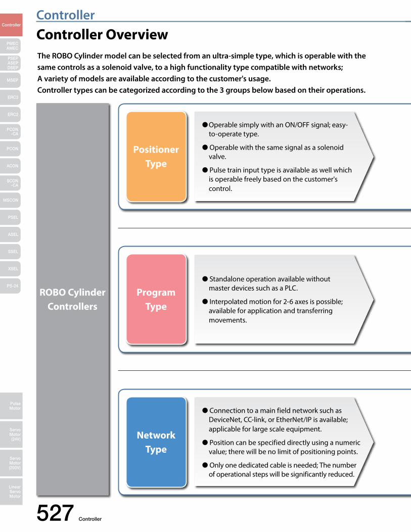
Controller OverviewThe ROBO Cylinder model can be selected from an ultra-simple type, which is operable with the same controls as a solenoid valve, to a high functionality type compatible with networks; A variety of models are available according to the customer's usage.Controller types can be categorized according to the 3 groups below based on their operations.
Operable simply with an ON/OFF signal; easy-to-operate type.
Operable with the same signal as a solenoid valve.
Pulse train input type is available as well which is operable freely based on the customer's control.
Standalone operation available without master devices such as a PLC.
Interpolated motion for 2-6 axes is possible; available for application and transferring movements.
Connection to a main field network such as DeviceNet, CC-link, or EtherNet/IP is available; applicable for large scale equipment.
Position can be specified directly using a numeric value; there will be no limit of positioning points.
Only one dedicated cable is needed; The number of operational steps will be significantly reduced.
ROBO Cylinder Controllers
Program Type
Network Type
Positioner Type
Controller 528
ControllerController
PMECAMEC
Controller
Pulse Motor
Servo Motor (24V)
Servo Motor (200V)
LinearServo Motor
PSEP ASEPDSEP
MSEP
ERC3
ERC2
PCON-CA
PCON
ACON
SCON-CA
MSCON
PSEL
ASEL
SSEL
XSEL
PS-24
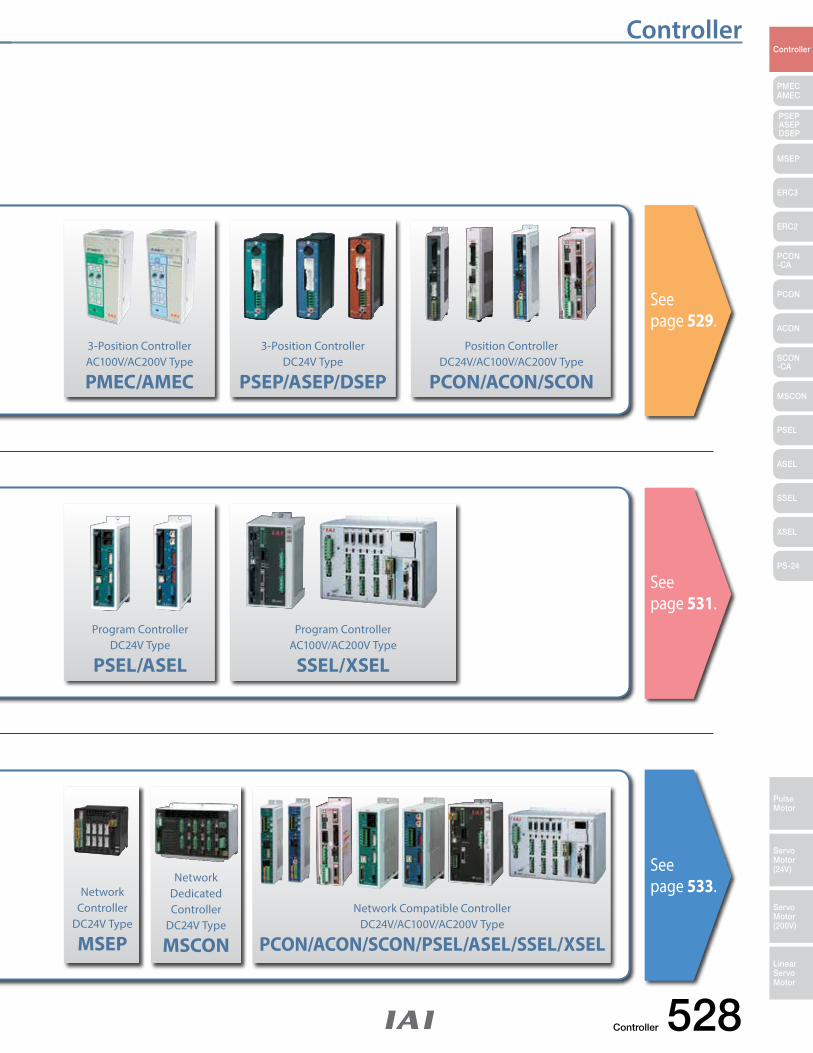
See page 529.
See page 531.
See page 533.
3-Position ControllerAC100V/AC200V Type
PMEC/AMEC
3-Position ControllerDC24V Type
PSEP/ASEP/DSEP
Program ControllerDC24V Type
PSEL/ASEL
Network Controller
DC24V Type
MSEP
Network Compatible ControllerDC24V/AC100V/AC200V Type
PCON/ACON/SCON/PSEL/ASEL/SSEL/XSEL
Network Dedicated Controller
DC24V Type
MSCON
Program ControllerAC100V/AC200V Type
SSEL/XSEL
Position ControllerDC24V/AC100V/AC200V Type
PCON/ACON/SCON
529 Controller
ControllerController
PMECAMEC
Controller
Pulse Motor
Servo Motor (24V)
Servo Motor (200V)
LinearServo Motor
PSEP ASEPDSEP
MSEP
ERC3
ERC2
PCON-CA
PCON
ACON
SCON-CA
MSCON
PSEL
ASEL
SSEL
XSEL
PS-24
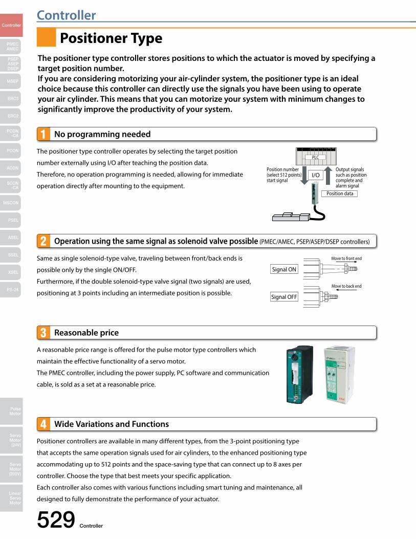
Positioner controllers are available in many different types, from the 3-point positioning type
that accepts the same operation signals used for air cylinders, to the enhanced positioning type
accommodating up to 512 points and the space-saving type that can connect up to 8 axes per
controller. Choose the type that best meets your specific application.
Each controller also comes with various functions including smart tuning and maintenance, all
designed to fully demonstrate the performance of your actuator.
Wide Variations and Functions 4
No programming needed1The positioner type controller operates by selecting the target position
number externally using I/O after teaching the position data.
Therefore, no operation programming is needed, allowing for immediate
operation directly after mounting to the equipment.
Output signals such as position complete and alarm signal
Position number (select 512 points) start signal
Position data
PLC
I/O
Same as single solenoid-type valve, traveling between front/back ends is
possible only by the single ON/OFF.
Furthermore, if the double solenoid-type valve signal (two signals) are used,
positioning at 3 points including an intermediate position is possible.
Operation using the same signal as solenoid valve possible (PMEC/AMEC, PSEP/ASEP/DSEP controllers)2
Signal ON
Signal OFF
Move to front end
Move to back end
Reasonable price3A reasonable price range is offered for the pulse motor type controllers which
maintain the effective functionality of a servo motor.
The PMEC controller, including the power supply, PC software and communication
cable, is sold as a set at a reasonable price.
The positioner type controller stores positions to which the actuator is moved by specifying a target position number.If you are considering motorizing your air-cylinder system, the positioner type is an ideal choice because this controller can directly use the signals you have been using to operate your air cylinder. This means that you can motorize your system with minimum changes to significantly improve the productivity of your system.
Positioner Type
Controller 530
ControllerController
PMECAMEC
Controller
Pulse Motor
Servo Motor (24V)
Servo Motor (200V)
LinearServo Motor
PSEP ASEPDSEP
MSEP
ERC3
ERC2
PCON-CA
PCON
ACON
SCON-CA
MSCON
PSEL
ASEL
SSEL
XSEL
PS-24
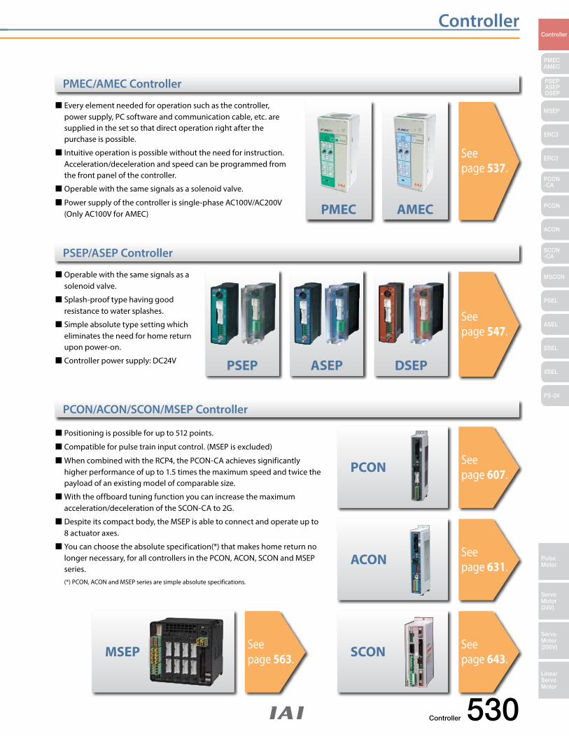
Every element needed for operation such as the controller, power supply, PC software and communication cable, etc. are supplied in the set so that direct operation right after the purchase is possible.
Intuitive operation is possible without the need for instruction. Acceleration/deceleration and speed can be programmed from
the front panel of the controller.
Operable with the same signals as a solenoid valve.
Power supply of the controller is single-phase AC100V/AC200V (Only AC100V for AMEC)
Operable with the same signals as a solenoid valve.
Splash-proof type having good resistance to water splashes.
Simple absolute type setting which eliminates the need for home return upon power-on.
Controller power supply: DC24V
Positioning is possible for up to 512 points.
Compatible for pulse train input control. (MSEP is excluded)
When combined with the RCP4, the PCON-CA achieves significantly higher performance of up to 1.5 times the maximum speed and twice the payload of an existing model of comparable size.
With the offboard tuning function you can increase the maximum acceleration/deceleration of the SCON-CA to 2G.
Despite its compact body, the MSEP is able to connect and operate up to 8 actuator axes.
You can choose the absolute specification(*) that makes home return no longer necessary, for all controllers in the PCON, ACON, SCON and MSEP series.
(*) PCON, ACON and MSEP series are simple absolute specifications.
PMEC
ASEP DSEP
PCON
ACON
SCONMSEP
PSEP
AMEC
PMEC/AMEC Controller
PSEP/ASEP Controller
PCON/ACON/SCON/MSEP Controller
See page 537.
See page 547.
See page 607.
See page 631.
See page 643.
See page 563.
531 Controller
ControllerController
PMECAMEC
Controller
Pulse Motor
Servo Motor (24V)
Servo Motor (200V)
LinearServo Motor
PSEP ASEPDSEP
MSEP
ERC3
ERC2
PCON-CA
PCON
ACON
SCON-CA
MSCON
PSEL
ASEL
SSEL
XSEL
PS-24
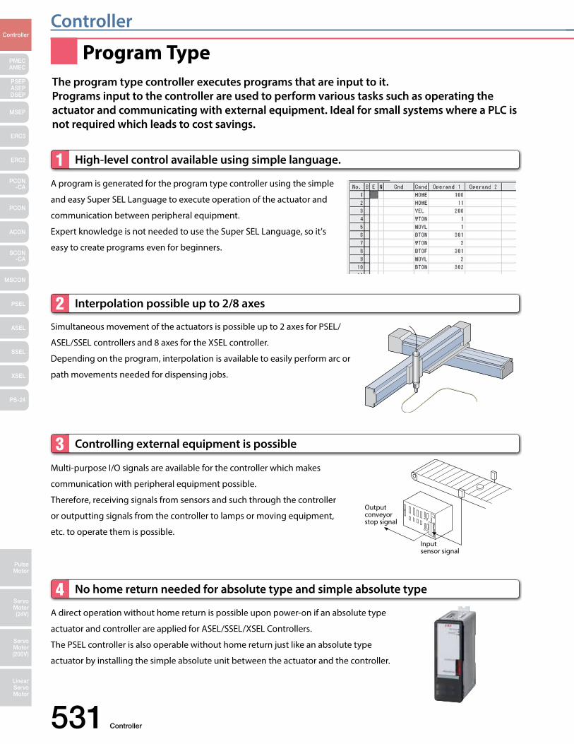
A program is generated for the program type controller using the simple
and easy Super SEL Language to execute operation of the actuator and
communication between peripheral equipment.
Expert knowledge is not needed to use the Super SEL Language, so it's
easy to create programs even for beginners.
High-level control available using simple language.1
Simultaneous movement of the actuators is possible up to 2 axes for PSEL/
ASEL/SSEL controllers and 8 axes for the XSEL controller.
Depending on the program, interpolation is available to easily perform arc or
path movements needed for dispensing jobs.
Interpolation possible up to 2/8 axes2
Output conveyor stop signal
Input sensor signal
Multi-purpose I/O signals are available for the controller which makes
communication with peripheral equipment possible.
Therefore, receiving signals from sensors and such through the controller
or outputting signals from the controller to lamps or moving equipment,
etc. to operate them is possible.
Controlling external equipment is possible3
A direct operation without home return is possible upon power-on if an absolute type
actuator and controller are applied for ASEL/SSEL/XSEL Controllers.
The PSEL controller is also operable without home return just like an absolute type
actuator by installing the simple absolute unit between the actuator and the controller.
No home return needed for absolute type and simple absolute type4
Program TypeThe program type controller executes programs that are input to it.Programs input to the controller are used to perform various tasks such as operating the actuator and communicating with external equipment. Ideal for small systems where a PLC is not required which leads to cost savings.
Controller 532
ControllerController
PMECAMEC
Controller
Pulse Motor
Servo Motor (24V)
Servo Motor (200V)
LinearServo Motor
PSEP ASEPDSEP
MSEP
ERC3
ERC2
PCON-CA
PCON
ACON
SCON-CA
MSCON
PSEL
ASEL
SSEL
XSEL
PS-24
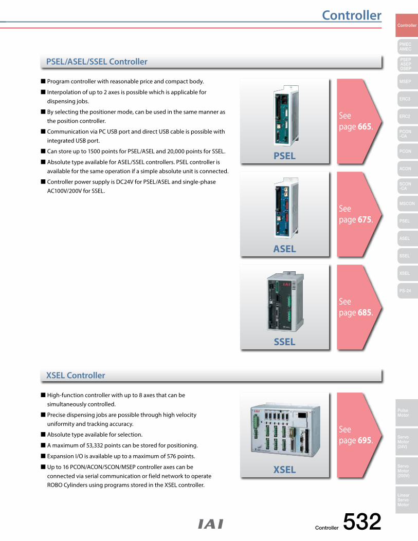
Program controller with reasonable price and compact body.
Interpolation of up to 2 axes is possible which is applicable for dispensing jobs.
By selecting the positioner mode, can be used in the same manner as the position controller.
Communication via PC USB port and direct USB cable is possible with integrated USB port.
Can store up to 1500 points for PSEL/ASEL and 20,000 points for SSEL.
Absolute type available for ASEL/SSEL controllers. PSEL controller is available for the same operation if a simple absolute unit is connected.
Controller power supply is DC24V for PSEL/ASEL and single-phase AC100V/200V for SSEL.
High-function controller with up to 8 axes that can be simultaneously controlled.
Precise dispensing jobs are possible through high velocity uniformity and tracking accuracy.
Absolute type available for selection.
A maximum of 53,332 points can be stored for positioning.
Expansion I/O is available up to a maximum of 576 points.
Up to 16 PCON/ACON/SCON/MSEP controller axes can be connected via serial communication or field network to operate ROBO Cylinders using programs stored in the XSEL controller.
PSEL
ASEL
SSEL
XSEL
PSEL/ASEL/SSEL Controller
XSEL Controller
See page 665.
See page 675.
See page 695.
See page 685.
533 Controller
ControllerController
PMECAMEC
Controller
Pulse Motor
Servo Motor (24V)
Servo Motor (200V)
LinearServo Motor
PSEP ASEPDSEP
MSEP
ERC3
ERC2
PCON-CA
PCON
ACON
SCON-CA
MSCON
PSEL
ASEL
SSEL
XSEL
PS-24
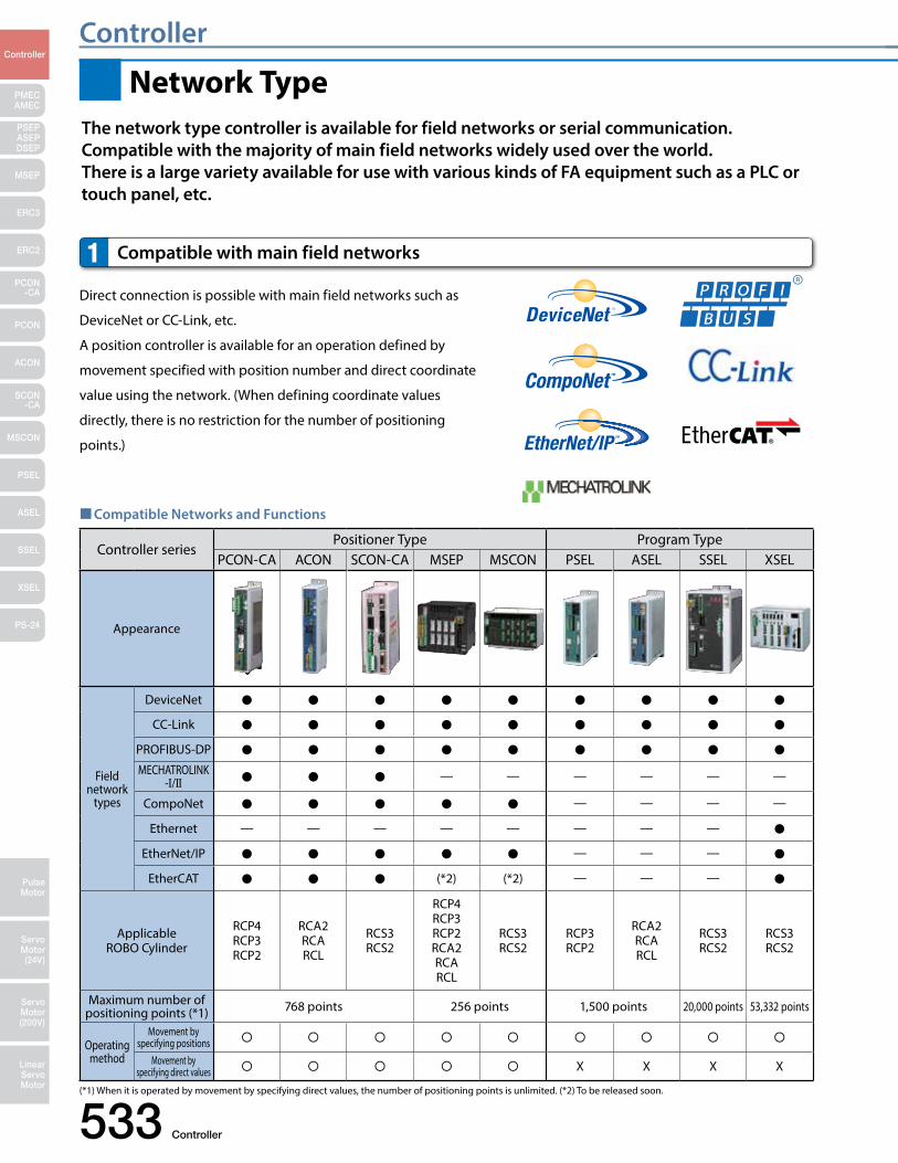
Compatible Networks and Functions
Network Type
Direct connection is possible with main field networks such as
DeviceNet or CC-Link, etc.
A position controller is available for an operation defined by
movement specified with position number and direct coordinate
value using the network. (When defining coordinate values
directly, there is no restriction for the number of positioning
points.)
Compatible with main field networks1
The network type controller is available for field networks or serial communication.Compatible with the majority of main field networks widely used over the world.There is a large variety available for use with various kinds of FA equipment such as a PLC or touch panel, etc.
Controller seriesPositioner Type Program Type
PCON-CA ACON SCON-CA MSEP MSCON PSEL ASEL SSEL XSEL
Appearance
Field network
types
DeviceNet
CC-Link
PROFIBUS-DP
MECHATROLINK-I/II — — — — — —
CompoNet — — — —
Ethernet — — — — — — — —
EtherNet/IP — — —
EtherCAT (*2) (*2) — — —
Applicable ROBO Cylinder
RCP4RCP3RCP2
RCA2RCARCL
RCS3RCS2
RCP4RCP3RCP2RCA2RCARCL
RCS3RCS2
RCP3RCP2
RCA2RCARCL
RCS3RCS2
RCS3RCS2
Maximum number of positioning points (*1) 768 points 256 points 1,500 points 20,000 points 53,332 points
Operating method
Movement by specifying positions
Movement by specifying direct values X X X X
(*1) When it is operated by movement by specifying direct values, the number of positioning points is unlimited. (*2) To be released soon.
Controller 534
ControllerController
PMECAMEC
Controller
Pulse Motor
Servo Motor (24V)
Servo Motor (200V)
LinearServo Motor
PSEP ASEPDSEP
MSEP
ERC3
ERC2
PCON-CA
PCON
ACON
SCON-CA
MSCON
PSEL
ASEL
SSEL
XSEL
PS-24
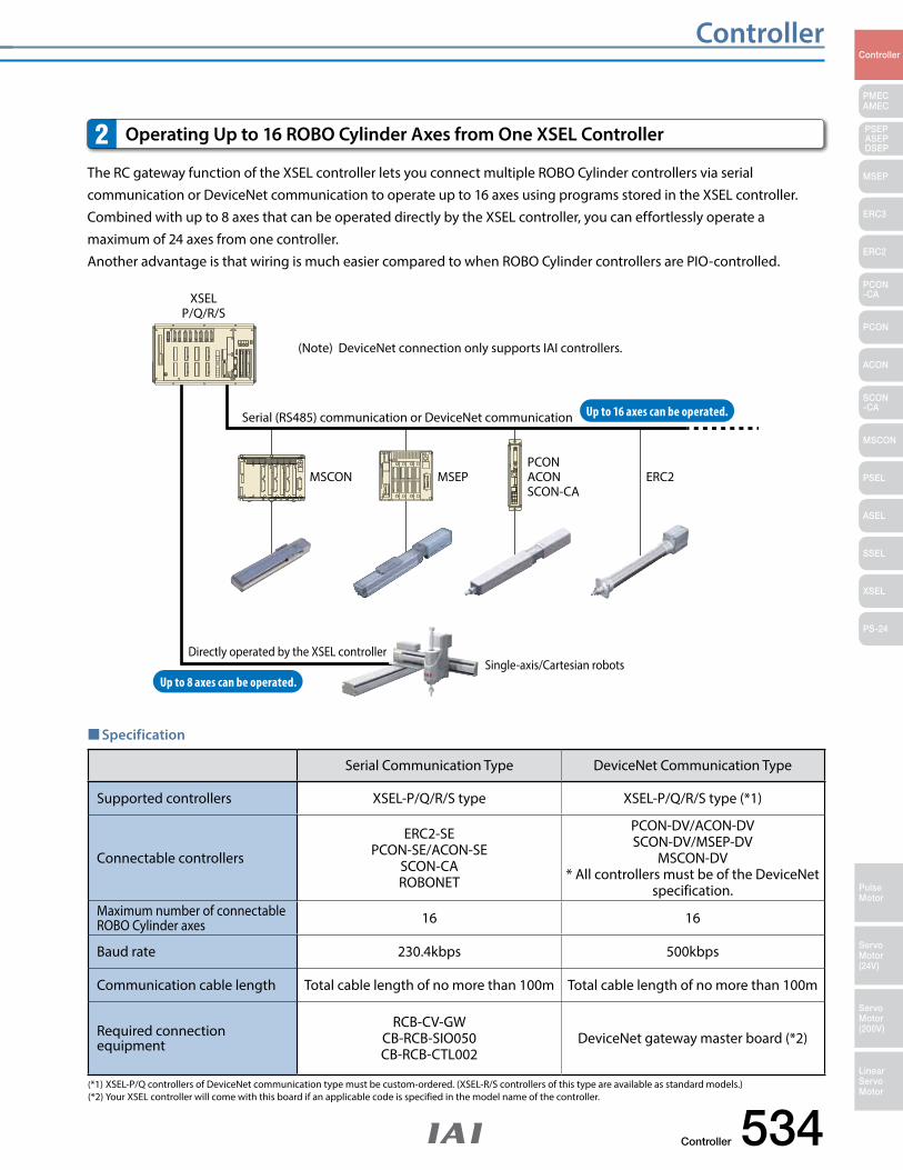
Specification
Serial Communication Type DeviceNet Communication Type
Supported controllers XSEL-P/Q/R/S type XSEL-P/Q/R/S type (*1)
Connectable controllers
ERC2-SEPCON-SE/ACON-SE
SCON-CAROBONET
PCON-DV/ACON-DVSCON-DV/MSEP-DV
MSCON-DV* All controllers must be of the DeviceNet
specification.Maximum number of connectable ROBO Cylinder axes 16 16
Baud rate 230.4kbps 500kbps
Communication cable length Total cable length of no more than 100m Total cable length of no more than 100m
Required connection equipment
RCB-CV-GWCB-RCB-SIO050CB-RCB-CTL002
DeviceNet gateway master board (*2)
(*1) XSEL-P/Q controllers of DeviceNet communication type must be custom-ordered. (XSEL-R/S controllers of this type are available as standard models.) (*2) Your XSEL controller will come with this board if an applicable code is specified in the model name of the controller.
The RC gateway function of the XSEL controller lets you connect multiple ROBO Cylinder controllers via serial communication or DeviceNet communication to operate up to 16 axes using programs stored in the XSEL controller. Combined with up to 8 axes that can be operated directly by the XSEL controller, you can effortlessly operate a maximum of 24 axes from one controller. Another advantage is that wiring is much easier compared to when ROBO Cylinder controllers are PIO-controlled.
Operating Up to 16 ROBO Cylinder Axes from One XSEL Controller 2
Serial (RS485) communication or DeviceNet communication
(Note) DeviceNet connection only supports IAI controllers.
Up to 16 axes can be operated.
Up to 8 axes can be operated.
XSELP/Q/R/S
Directly operated by the XSEL controller
MSCON MSEP ERC2
Single-axis/Cartesian robots
PCONACONSCON-CA
535 Controller
ControllerController
PMECAMEC
Controller
Pulse Motor
Servo Motor (24V)
Servo Motor (200V)
LinearServo Motor
PSEP ASEPDSEP
MSEP
ERC3
ERC2
PCON-CA
PCON
ACON
SCON-CA
MSCON
PSEL
ASEL
SSEL
XSEL
PS-24
Coordinatevalues
Cameracontroller
Controller
Position data
XSELR/S
PLC
CC-Link
I/Os communications
Ethernet
Vision system data
Omron
Keyence
Cognex
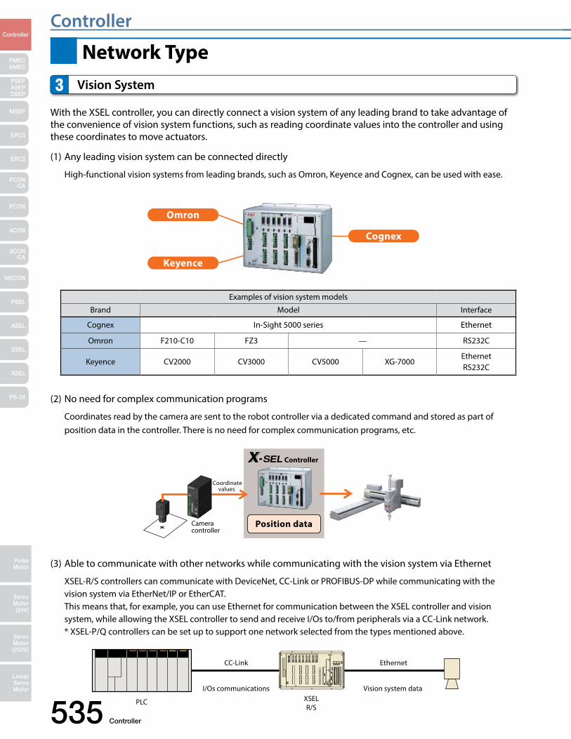
With the XSEL controller, you can directly connect a vision system of any leading brand to take advantage of the convenience of vision system functions, such as reading coordinate values into the controller and using these coordinates to move actuators.
(1) Any leading vision system can be connected directly
High-functional vision systems from leading brands, such as Omron, Keyence and Cognex, can be used with ease.
(2) No need for complex communication programs
Coordinates read by the camera are sent to the robot controller via a dedicated command and stored as part of position data in the controller. There is no need for complex communication programs, etc.
(3) Able to communicate with other networks while communicating with the vision system via Ethernet
XSEL-R/S controllers can communicate with DeviceNet, CC-Link or PROFIBUS-DP while communicating with the vision system via EtherNet/IP or EtherCAT. This means that, for example, you can use Ethernet for communication between the XSEL controller and vision system, while allowing the XSEL controller to send and receive I/Os to/from peripherals via a CC-Link network. * XSEL-P/Q controllers can be set up to support one network selected from the types mentioned above.
Vision System 3
Network Type
Examples of vision system models
Brand Model Interface
Cognex In-Sight 5000 series Ethernet
Omron F210-C10 FZ3 — RS232C
Keyence CV2000 CV3000 CV5000 XG-7000EthernetRS232C
Controller 536
ControllerController
PMECAMEC
Controller
Pulse Motor
Servo Motor (24V)
Servo Motor (200V)
LinearServo Motor
PSEP ASEPDSEP
MSEP
ERC3
ERC2
PCON-CA
PCON
ACON
SCON-CA
MSCON
PSEL
ASEL
SSEL
XSEL
PS-24
SCON
SSEL
PCON ACON
XSEL
PSEL ASEL
MSEP
MSCON
See page 643.
See page 631.
See page 607.
See page 658.
See page 675.
See page 665.
See page 695.
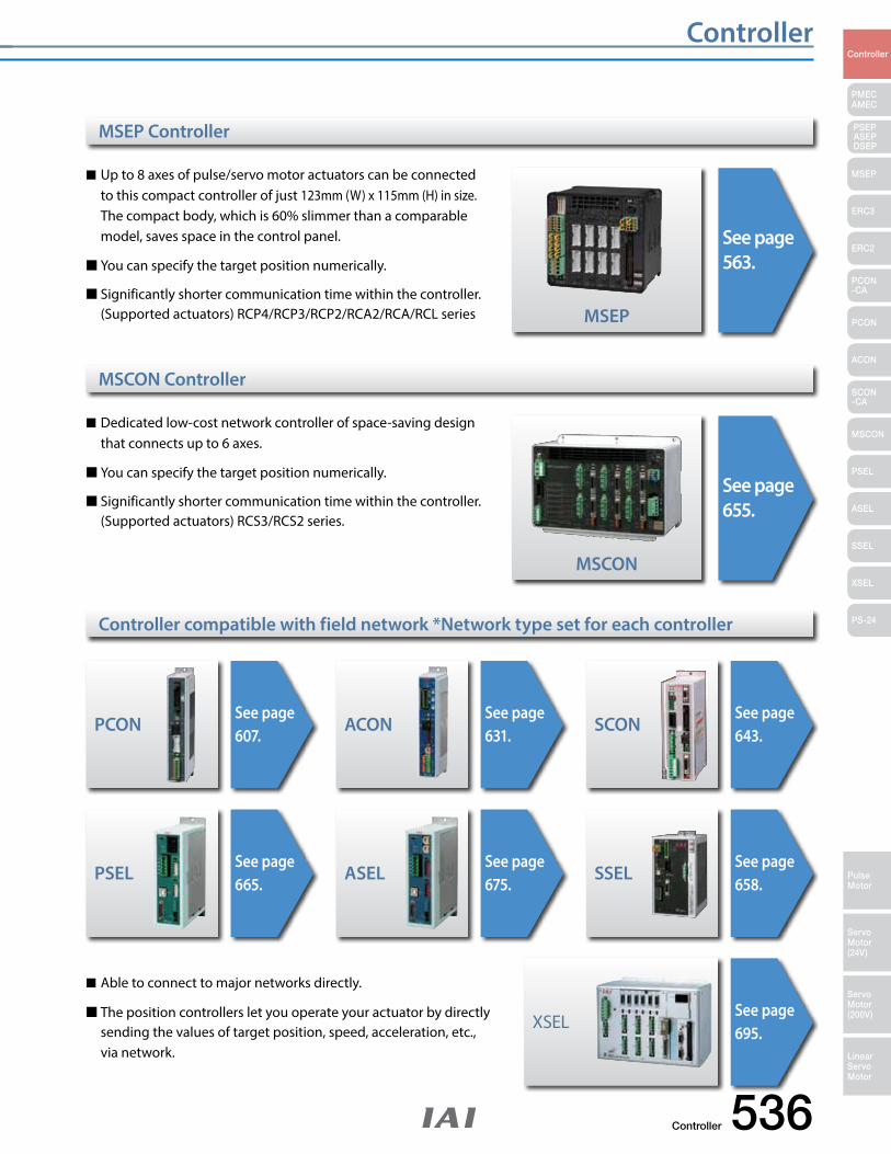
MSCON Controller
Controller compatible with field network *Network type set for each controller
See page 563.
See page 655.
Up to 8 axes of pulse/servo motor actuators can be connected to this compact controller of just 123mm (W) x 115mm (H) in size. The compact body, which is 60% slimmer than a comparable model, saves space in the control panel.
You can specify the target position numerically.
Significantly shorter communication time within the controller. (Supported actuators) RCP4/RCP3/RCP2/RCA2/RCA/RCL series
Dedicated low-cost network controller of space-saving design that connects up to 6 axes.
You can specify the target position numerically.
Significantly shorter communication time within the controller. (Supported actuators) RCS3/RCS2 series.
Able to connect to major networks directly.
The position controllers let you operate your actuator by directly sending the values of target position, speed, acceleration, etc., via network.
MSEP Controller
PMEC/AMEC Controller
537 PMEC / AMEC
PMECAMEC
Controller
Pulse Motor
Servo Motor (24V)
Servo Motor (200V)
LinearServo Motor
PSEP ASEPDSEP
MSEP
ERC3
ERC2
PCON-CA
PCON
ACON
SCON-CA
MSCON
PSEL
ASEL
SSEL
XSEL
PS-24
Controller
Power supply
PC connection cable
2 Adjustment
1Manual setting
3 Trial operation
ReplacementAir cylinder ROBO cylinder
PLC
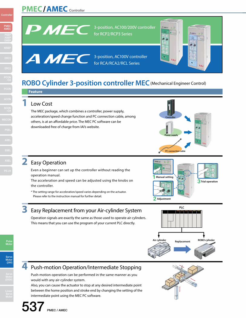
3-position, AC100/200V controller for RCP2/RCP3 Series
3-position, AC100V controller for RCA/RCA2/RCL Series
1 Low Cost The MEC package, which combines a controller, power supply,
acceleration/speed change function and PC connection cable, among others, is at an affordable price. The MEC PC software can be downloaded free of charge from IAI’s website.
2 Easy Operation Even a beginner can set up the controller without reading the
operation manual. The acceleration and speed can be adjusted using the knobs on
the controller.
* The setting range for acceleration/speed varies depending on the actuator. Please refer to the instruction manual for further detail.
3 Easy Replacement from your Air-cylinder System Operation signals are exactly the same as those used to operate air cylinders. This means that you can use the program of your current PLC directly.
ROBO Cylinder 3-position controller MEC (Mechanical Engineer Control)
Feature
4 Push-motion Operation/Intermediate Stopping Push-motion operation can be performed in the same manner as you
would with any air-cylinder system. Also, you can cause the actuator to stop at any desired intermediate point
between the home position and stroke end by changing the setting of the intermediate point using the MEC PC software.
PMEC/AMEC Controller
PMEC / AMEC 538
PMECAMEC
Controller
Pulse Motor
Servo Motor (24V)
Servo Motor (200V)
LinearServo Motor
PSEP ASEPDSEP
MSEP
ERC3
ERC2
PCON-CA
PCON
ACON
SCON-CA
MSCON
PSEL
ASEL
SSEL
XSEL
PS-24
Model
Model List
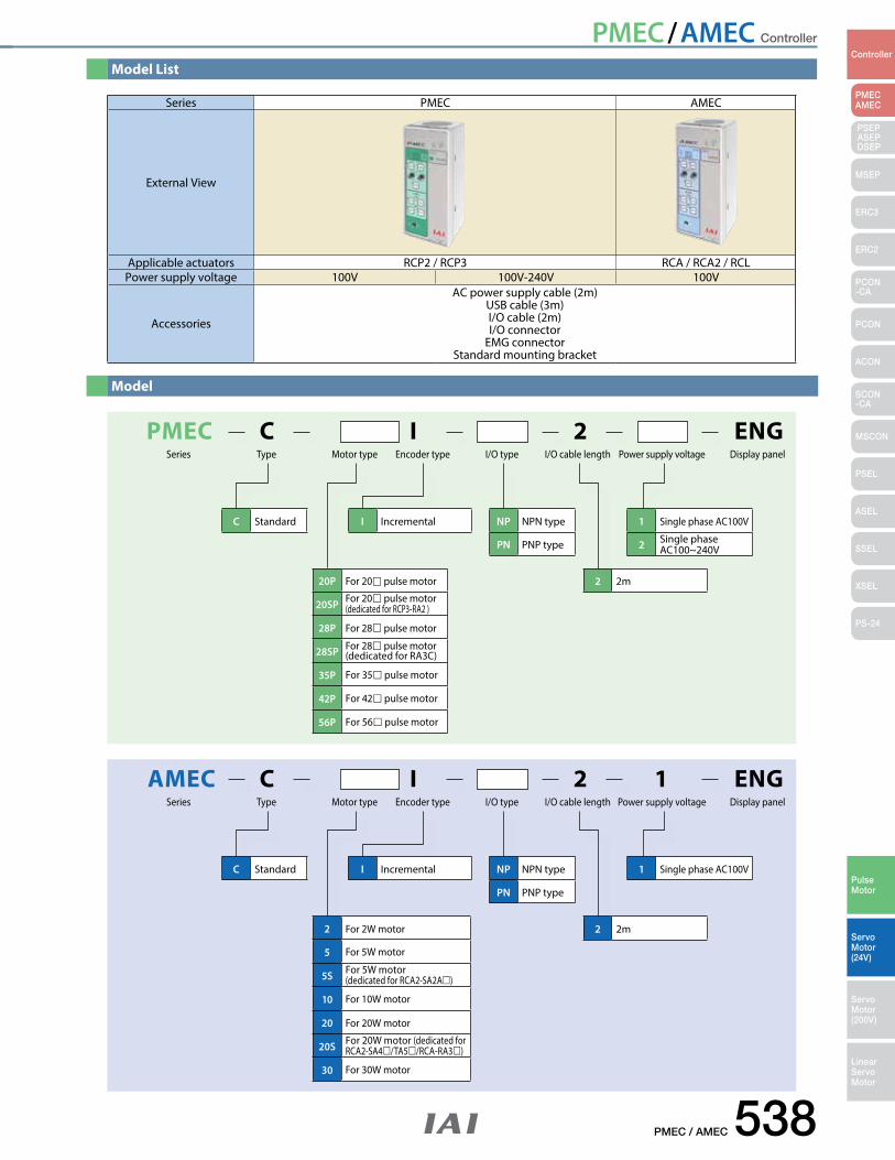
Series PMEC AMEC
External View
Applicable actuators RCP2 / RCP3 RCA / RCA2 / RCLPower supply voltage 100V 100V-240V 100V
Accessories
AC power supply cable (2m)USB cable (3m)I/O cable (2m)I/O connector
EMG connectorStandard mounting bracket
I IncrementalC Standard
2 2m
NP NPN type
PN PNP type
1 Single phase AC100V
2 Single phaseAC100~240V
20P For 20 pulse motor
20SP For 20 pulse motor (dedicated for RCP3-RA2 )
28P For 28 pulse motor
28SP For 28 pulse motor (dedicated for RA3C)
35P For 35 pulse motor
42P For 42 pulse motor
56P For 56 pulse motor
PMEC C ENGI 2Series Type I/O type I/O cable length Power supply voltage Display panelMotor type Encoder type
I IncrementalC Standard
2 2m
NP NPN type
PN PNP type
1 Single phase AC100V
2 For 2W motor
5 For 5W motor
5S For 5W motor (dedicated for RCA2-SA2A)
10 For 10W motor
20 For 20W motor
20S For 20W motor (dedicated for RCA2-SA4/TA5/RCA-RA3)
30 For 30W motor
AMEC C ENGI 2 1Series Type I/O type I/O cable length Power supply voltage Display panelMotor type Encoder type
PMEC/AMEC Controller
539 PMEC / AMEC
PMECAMEC
Controller
Pulse Motor
Servo Motor (24V)
Servo Motor (200V)
LinearServo Motor
PSEP ASEPDSEP
MSEP
ERC3
ERC2
PCON-CA
PCON
ACON
SCON-CA
MSCON
PSEL
ASEL
SSEL
XSEL
PS-24
PLC
PIO Unit
Emergency stop switchI/O cable (2m)
I/O connector
(At the time of shipment, the EMG connector is short-circuited.)
See page P546 formaintenance cables.
downloadPC software
Teaching Pendant forROBO Cylinder( See P543)<Model CON-PTA-C><Model CON-PDA-C><Model CON-PGAS-C-S>
Option
Supplied with the actuatorMotor-Encoder Integrated Cable
Supplied with the controller
Supplied with the controller
Supplied with the controller
Supplied with the controller
Power cable (2m)USB cable (3m)
Actuator
PMEC
See page P545 formaintenance cables.
AMEC
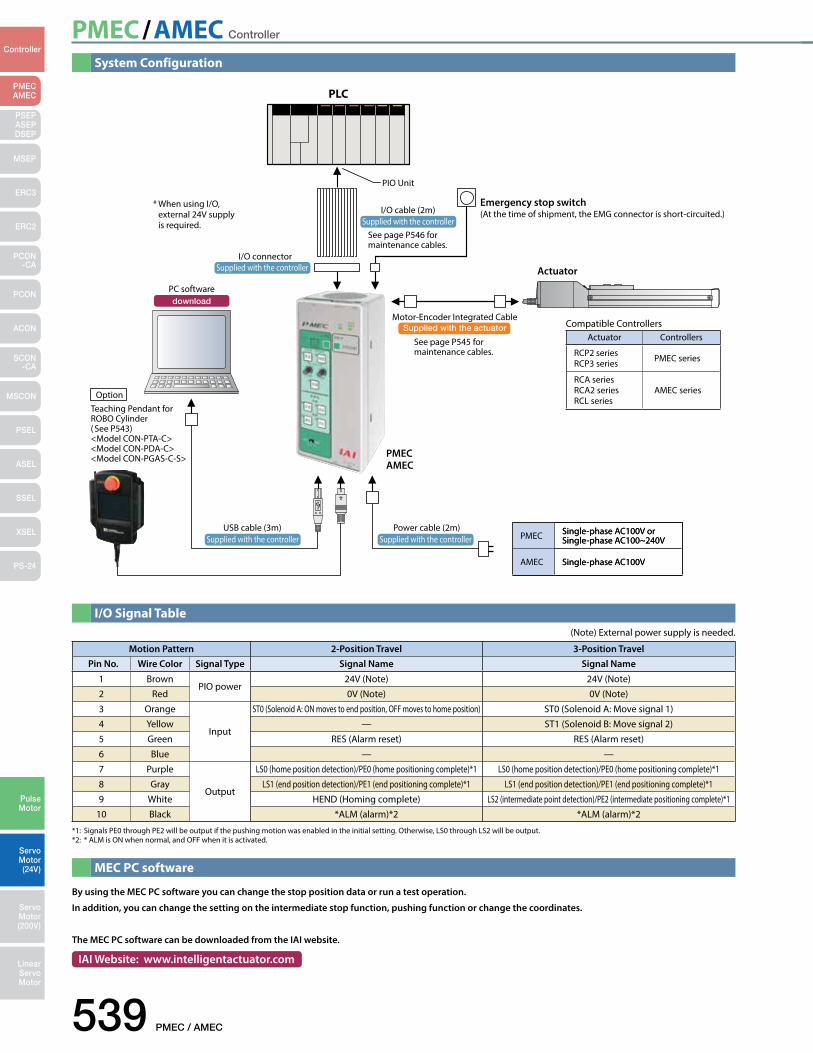
System Configuration
PMEC Single-phase AC100V or Single-phase AC100~240V
AMEC Single-phase AC100V
I/O Signal Table
MEC PC software
Compatible ControllersActuator Controllers
RCP2 seriesRCP3 series PMEC series
RCA seriesRCA2 seriesRCL series
AMEC series
PMEC Single-phase AC100V or Single-phase AC100~240V
AMEC Single-phase AC100V
Motion Pattern 2-Position Travel 3-Position TravelPin No. Wire Color Signal Type Signal Name Signal Name
1 BrownPIO power
24V (Note) 24V (Note)2 Red 0V (Note) 0V (Note)
3 Orange
Input
ST0 (Solenoid A: ON moves to end position, OFF moves to home position) ST0 (Solenoid A: Move signal 1)
4 Yellow — ST1 (Solenoid B: Move signal 2)
5 Green RES (Alarm reset) RES (Alarm reset)
6 Blue — —
7 Purple
Output
LS0 (home position detection)/PE0 (home positioning complete)*1 LS0 (home position detection)/PE0 (home positioning complete)*1
8 Gray LS1 (end position detection)/PE1 (end positioning complete)*1 LS1 (end position detection)/PE1 (end positioning complete)*1
9 White HEND (Homing complete) LS2 (intermediate point detection)/PE2 (intermediate positioning complete)*110 Black *ALM (alarm)*2 *ALM (alarm)*2
*1: Signals PE0 through PE2 will be output if the pushing motion was enabled in the initial setting. Otherwise, LS0 through LS2 will be output.*2: * ALM is ON when normal, and OFF when it is activated.
By using the MEC PC software you can change the stop position data or run a test operation.
In addition, you can change the setting on the intermediate stop function, pushing function or change the coordinates.
The MEC PC software can be downloaded from the IAI website.
IAI Website: www.intelligentactuator.com
(Note) External power supply is needed.
* When using I/O, external 24V supply is required.
PMEC/AMEC Controller
PMEC / AMEC 540
PMECAMEC
Controller
Pulse Motor
Servo Motor (24V)
Servo Motor (200V)
LinearServo Motor
PSEP ASEPDSEP
MSEP
ERC3
ERC2
PCON-CA
PCON
ACON
SCON-CA
MSCON
PSEL
ASEL
SSEL
XSEL
PS-24
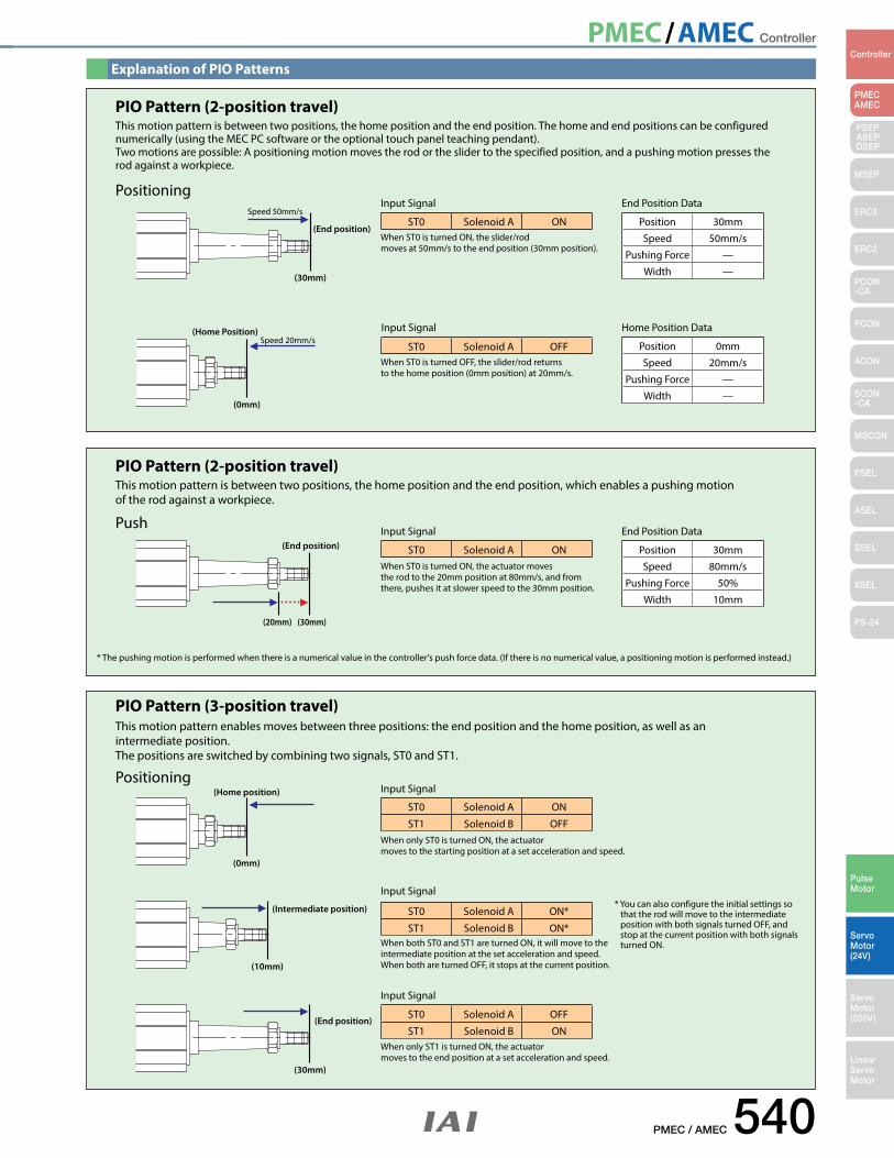
Explanation of PIO Patterns
ST0 Solenoid A ON
Position 0mm
Speed 20mm/s
Pushing Force —
Width —
Position 30mm
Speed 50mm/s
Pushing Force —
Width —
ST0 Solenoid A OFF
End Position DataInput SignalPositioning
When ST0 is turned ON, the slider/rod moves at 50mm/s to the end position (30mm position).
This motion pattern is between two positions, the home position and the end position. The home and end positions can be configured numerically (using the MEC PC software or the optional touch panel teaching pendant).Two motions are possible: A positioning motion moves the rod or the slider to the specified position, and a pushing motion presses the rod against a workpiece.
When ST0 is turned OFF, the slider/rod returns to the home position (0mm position) at 20mm/s.
Home Position DataInput Signal
PIO Pattern (2-position travel)
(End position)
(30mm)
(0mm)
(Home Position)
Speed 50mm/s
Speed 20mm/s
ST0 Solenoid A ON Position 30mm
Speed 80mm/s
Pushing Force 50%
Width 10mm
End Position DataInput SignalPush
This motion pattern is between two positions, the home position and the end position, which enables a pushing motion of the rod against a workpiece.
When ST0 is turned ON, the actuator moves the rod to the 20mm position at 80mm/s, and from there, pushes it at slower speed to the 30mm position.
* The pushing motion is performed when there is a numerical value in the controller's push force data. (If there is no numerical value, a positioning motion is performed instead.)
PIO Pattern (2-position travel)
(End position)
(30mm)(20mm)
ST0 Solenoid A ON
ST1 Solenoid B OFF
ST0 Solenoid A ON*
ST1 Solenoid B ON*
ST0 Solenoid A OFF
ST1 Solenoid B ON
Input Signal
Input Signal
Input Signal
Positioning
This motion pattern enables moves between three positions: the end position and the home position, as well as an intermediate position. The positions are switched by combining two signals, ST0 and ST1.
When only ST0 is turned ON, the actuator moves to the starting position at a set acceleration and speed.
When both ST0 and ST1 are turned ON, it will move to the intermediate position at the set acceleration and speed. When both are turned OFF, it stops at the current position.
When only ST1 is turned ON, the actuator moves to the end position at a set acceleration and speed.
* You can also configure the initial settings so that the rod will move to the intermediate position with both signals turned OFF, and stop at the current position with both signals turned ON.
PIO Pattern (3-position travel)
(0mm)
(Home position)
(Intermediate position)
(10mm)
(End position)
(30mm)
PMEC/AMEC Controller
541 PMEC / AMEC
PMECAMEC
Controller
Pulse Motor
Servo Motor (24V)
Servo Motor (200V)
LinearServo Motor
PSEP ASEPDSEP
MSEP
ERC3
ERC2
PCON-CA
PCON
ACON
SCON-CA
MSCON
PSEL
ASEL
SSEL
XSEL
PS-24
PowerGreen :Normal
Red: Alarm
CompleteHOME
SAVE
Test run
Manual
Manual
Continuous
Auto
Ext. Start
Accel & Speed Setting
FWDPOS
BACKPOS
Middle
Accel Speed
FWD BACK
RUN STOP
Normal Release
Brake
Teaching Port
226
216
85 2-ø5 through
200
42.5
8289.8
2
87.880
182
99
PowerGreen :Normal
Red: Alarm
CompleteHOME
SAVE
Test run
Manual
Manual
Continuous
Auto
Ext. Start
Accel & Speed Setting
FWDPOS
BACKPOS
Middle
Accel Speed
FWD BACK
RUN STOP
Normal Release
Brake
Teaching Port
85
200
4.1
8.5 8.568
4-M3 tapped hole
[With standard mounting bracket]
The standard mounting bracket is supplied with the controller.
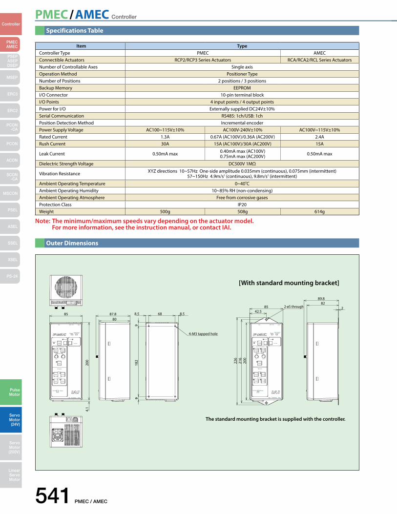
Specifications Table
Outer Dimensions
Item TypeController Type PMEC AMECConnectible Actuators RCP2/RCP3 Series Actuators RCA/RCA2/RCL Series ActuatorsNumber of Controllable Axes Single axisOperation Method Positioner TypeNumber of Positions 2 positions / 3 positionsBackup Memory EEPROMI/O Connector 10-pin terminal blockI/O Points 4 input points / 4 output pointsPower for I/O Externally supplied DC24V±10%Serial Communication RS485: 1ch/USB: 1chPosition Detection Method Incremental encoderPower Supply Voltage AC100~115V±10% AC100V-240V±10% AC100V~115V±10%Rated Current 1.3A 0.67A (AC100V)/0.36A (AC200V) 2.4ARush Current 30A 15A (AC100V)/30A (AC200V) 15A
Leak Current 0.50mA max 0.40mA max (AC100V)0.75mA max (AC200V) 0.50mA max
Dielectric Strength Voltage DC500V 1MΩ
Vibration Resistance XYZ directions 10~57Hz One-side amplitude 0.035mm (continuous), 0.075mm (intermittent)57~150Hz 4.9m/s2 (continuous), 9.8m/s2 (intermittent)
Ambient Operating Temperature 0~40CAmbient Operating Humidity 10~85% RH (non-condensing)Ambient Operating Atmosphere Free from corrosive gasesProtection Class IP20Weight 500g 508g 614g
Note: The minimum/maximum speeds vary depending on the actuator model. For more information, see the instruction manual, or contact IAI.
PMEC/AMEC Controller
PMEC / AMEC 542
PMECAMEC
Controller
Pulse Motor
Servo Motor (24V)
Servo Motor (200V)
LinearServo Motor
PSEP ASEPDSEP
MSEP
ERC3
ERC2
PCON-CA
PCON
ACON
SCON-CA
MSCON
PSEL
ASEL
SSEL
XSEL
PS-24
1
2
3
4
567
89
10
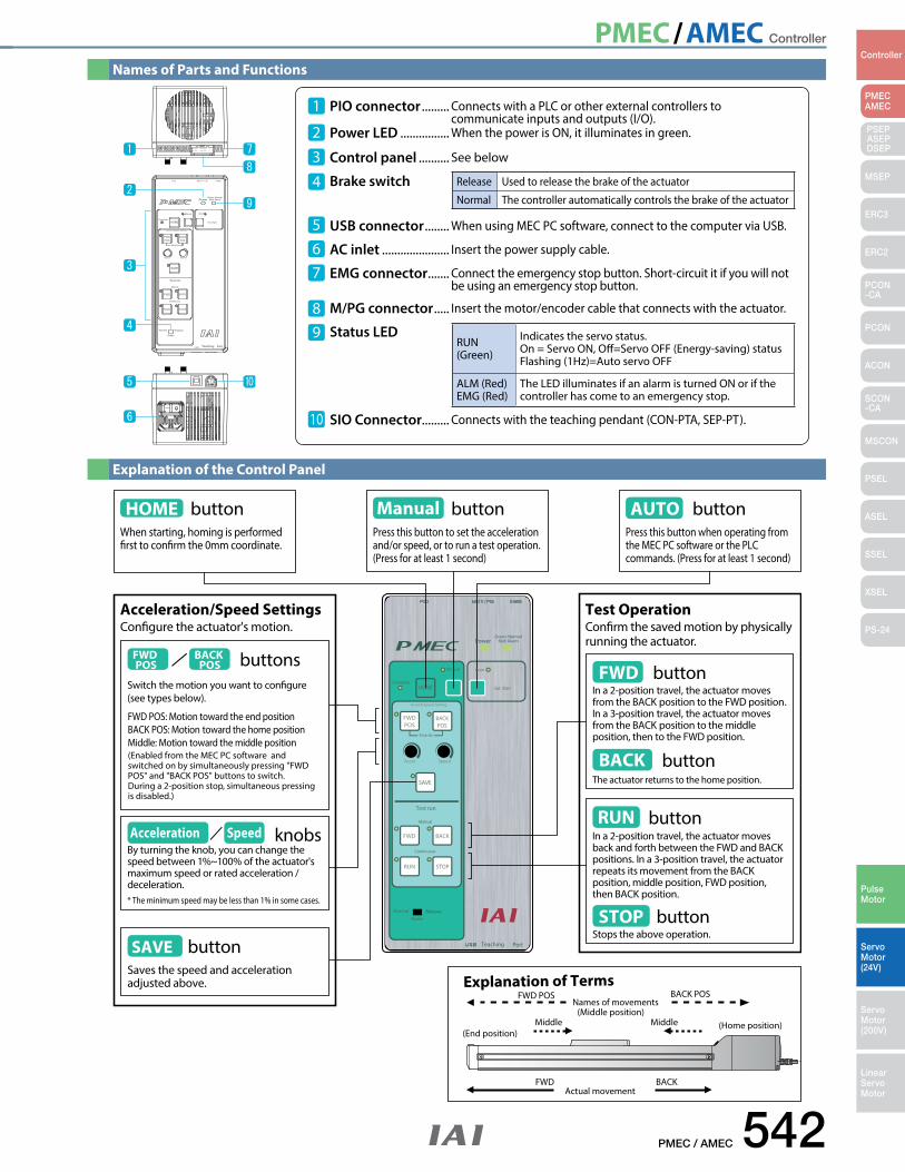
PIO connector ......... Connects with a PLC or other external controllers to communicate inputs and outputs (I/O).Power LED ................ When the power is ON, it illuminates in green.
Control panel .......... See below
Brake switch
USB connector ........ When using MEC PC software, connect to the computer via USB.
AC inlet ...................... Insert the power supply cable.
EMG connector ....... Connect the emergency stop button. Short-circuit it if you will not be using an emergency stop button.
M/PG connector ..... Insert the motor/encoder cable that connects with the actuator.
Status LED
SIO Connector......... Connects with the teaching pendant (CON-PTA, SEP-PT).
Release Used to release the brake of the actuator
Normal The controller automatically controls the brake of the actuator
RUN (Green)
Indicates the servo status. On = Servo ON, Off=Servo OFF (Energy-saving) statusFlashing (1Hz)=Auto servo OFF
ALM (Red)EMG (Red)
The LED illuminates if an alarm is turned ON or if the controller has come to an emergency stop.
PowerGreen :Normal
Red: Alarm
CompleteHOME
SAVE
Test run
Manual
Manual
Continuous
Auto
Ext. Start
Accel & Speed Setting
FWDPOS
BACKPOS
Middle
Accel Speed
FWD BACK
RUN STOP
Normal Release
Brake
Teaching Port
PowerGreen :Normal
Red: Alarm
CompleteHOME
SAVE
Test run
Manual
Manual
Continuous
Auto
Ext. Start
Accel & Speed Setting
FWDPOS
BACKPOS
Middle
Accel Speed
FWD BACK
RUN STOP
Normal Release
Brake
Teaching Port
AUTO buttonPress this button when operating from the MEC PC software or the PLC commands. (Press for at least 1 second)
Congure the actuator's motion.
buttonHOMEWhen starting, homing is performed rst to conrm the 0mm coordinate.
Explanation of Terms
(Enabled from the MEC PC software and switched on by simultaneously pressing "FWD POS" and "BACK POS" buttons to switch. During a 2-position stop, simultaneous pressing is disabled.)
FWD POS: Motion toward the end positionBACK POS: Motion toward the home positionMiddle: Motion toward the middle position
FWD POS
BACK POS buttons
Switch the motion you want to congure (see types below).
Acceleration/Speed Settings
SAVE buttonSaves the speed and acceleration adjusted above.
Conrm the saved motion by physically running the actuator.
Test Operation
FWD buttonIn a 2-position travel, the actuator moves from the BACK position to the FWD position. In a 3-position travel, the actuator moves from the BACK position to the middle position, then to the FWD position.
BACK buttonThe actuator returns to the home position.
RUN buttonIn a 2-position travel, the actuator moves back and forth between the FWD and BACK positions. In a 3-position travel, the actuator repeats its movement from the BACK position, middle position, FWD position, then BACK position.
STOP buttonStops the above operation.
Press this button to set the acceleration and/or speed, or to run a test operation. (Press for at least 1 second)
Manual button
FWD POS BACK POS
Middle(Middle position)
FWD BACKActual movement
(End position)(Home position)Middle
Names of movements
Acceleration Speed knobsBy turning the knob, you can change the speed between 1%~100% of the actuator's maximum speed or rated acceleration / deceleration.* The minimum speed may be less than 1% in some cases.
Names of Parts and Functions
Explanation of the Control Panel
PMEC/AMEC Controller
543 PMEC / AMEC
PMECAMEC
Controller
Pulse Motor
Servo Motor (24V)
Servo Motor (200V)
LinearServo Motor
PSEP ASEPDSEP
MSEP
ERC3
ERC2
PCON-CA
PCON
ACON
SCON-CA
MSCON
PSEL
ASEL
SSEL
XSEL
PS-24
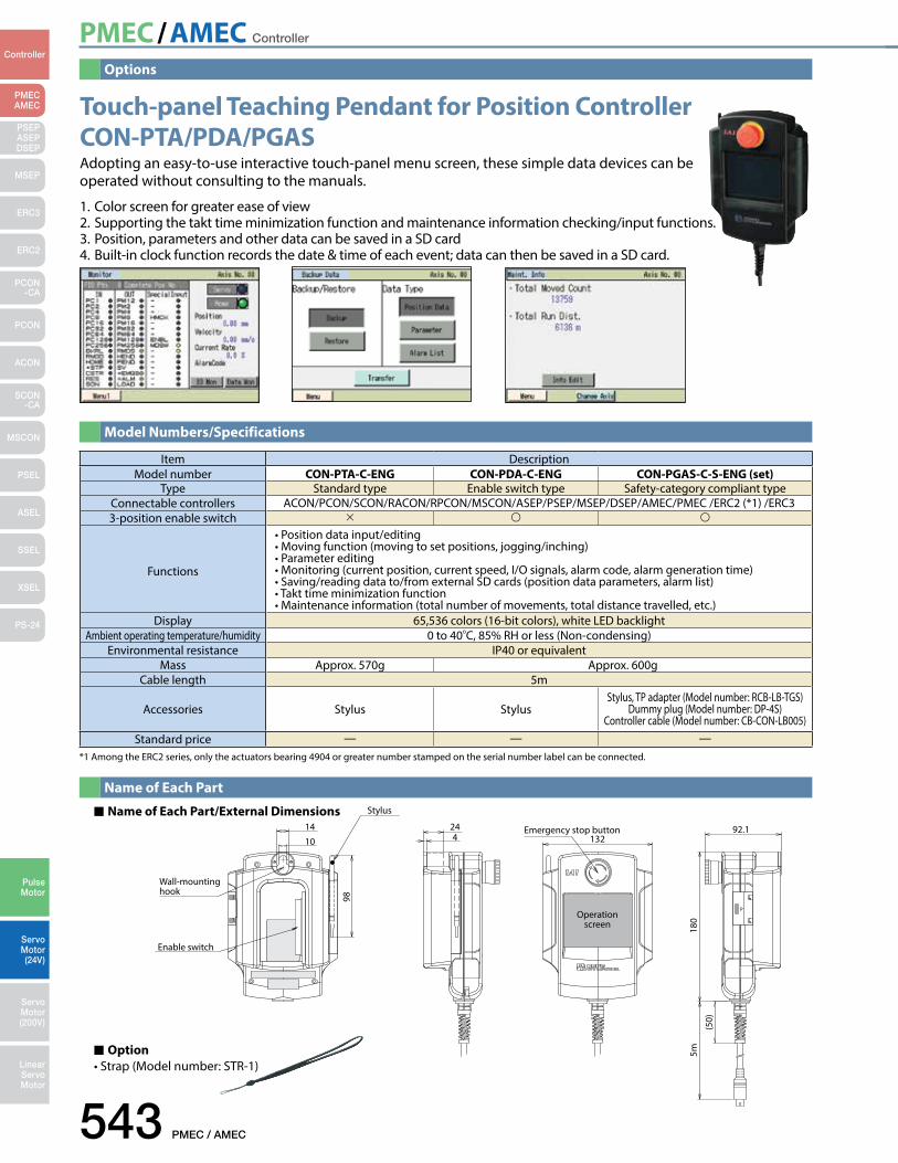
*1 Among the ERC2 series, only the actuators bearing 4904 or greater number stamped on the serial number label can be connected.
Item DescriptionModel number CON-PTA-C-ENG CON-PDA-C-ENG CON-PGAS-C-S-ENG (set)
Type Standard type Enable switch type Safety-category compliant typeConnectable controllers ACON/PCON/SCON/RACON/RPCON/MSCON/ASEP/PSEP/MSEP/DSEP/AMEC/PMEC /ERC2 (*1) /ERC33-position enable switch
Functions
•Positiondatainput/editing•Movingfunction(movingtosetpositions,jogging/inching)•Parameterediting•Monitoring(currentposition,currentspeed,I/Osignals,alarmcode,alarmgenerationtime)•Saving/readingdatato/fromexternalSDcards(positiondataparameters,alarmlist)•Takttimeminimizationfunction•Maintenanceinformation(totalnumberofmovements,totaldistancetravelled,etc.)
Display 65,536 colors (16-bit colors), white LED backlightAmbient operating temperature/humidity 0 to 40C, 85% RH or less (Non-condensing)
Environmental resistance IP40 or equivalentMass Approx. 570g Approx. 600g
Cable length 5m
Accessories Stylus StylusStylus, TP adapter (Model number: RCB-LB-TGS)
Dummy plug (Model number: DP-4S)Controller cable (Model number: CB-CON-LB005)
Standard price — — —
Options
Model Numbers/Specifications
Name of Each Part
Name of Each Part/External Dimensions Stylus
Wall-mounting hook
Enable switch
14 24
10 4
98
Emergency stop button
Operation screen
13292.1
180
5m
(50)
Option•Strap(Modelnumber:STR-1)
Touch-panel Teaching Pendant for Position Controller CON-PTA/PDA/PGAS Adopting an easy-to-use interactive touch-panel menu screen, these simple data devices can be operated without consulting to the manuals.
1. Color screen for greater ease of view2. Supporting the takt time minimization function and maintenance information checking/input functions.3. Position, parameters and other data can be saved in a SD card4. Built-in clock function records the date & time of each event; data can then be saved in a SD card.
PMEC/AMEC Controller
PMEC / AMEC 544
PMECAMEC
Controller
Pulse Motor
Servo Motor (24V)
Servo Motor (200V)
LinearServo Motor
PSEP ASEPDSEP
MSEP
ERC3
ERC2
PCON-CA
PCON
ACON
SCON-CA
MSCON
PSEL
ASEL
SSEL
XSEL
PS-24
85
100
100
200
16
96
103.8
PowerGreen :NormalRed: Alarm
CompleteHOME
SAVE
Test run
Manual
Manual
Continuous
Auto
Ext. Start
Accel & Speed Setting
FWDPOS
BACKPOS
Middle
Accel Speed
FWD BACK
RUN STOP
Normal Release
Brake
Teaching Port
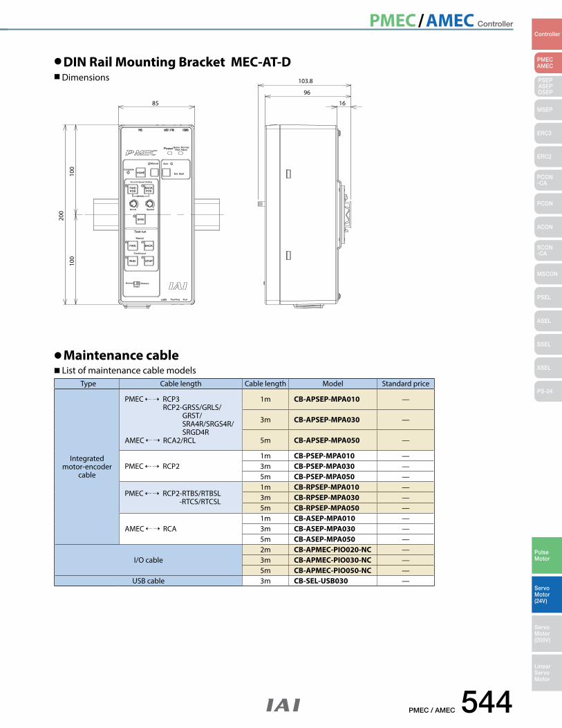
DIN Rail Mounting Bracket MEC-AT-D Dimensions
Maintenance cable List of maintenance cable models
Type Cable length Cable length Model Standard price
Integrated motor-encoder
cable
PMEC RCP3 RCP2-GRSS/GRLS/ GRST/ SRA4R/SRGS4R/ SRGD4RAMEC RCA2/RCL
1m CB-APSEP-MPA010 —
3m CB-APSEP-MPA030 —
5m CB-APSEP-MPA050 —
PMEC RCP21m CB-PSEP-MPA010 —3m CB-PSEP-MPA030 —5m CB-PSEP-MPA050 —
PMEC RCP2-RTBS/RTBSL -RTCS/RTCSL
1m CB-RPSEP-MPA010 —3m CB-RPSEP-MPA030 —5m CB-RPSEP-MPA050 —
AMEC RCA1m CB-ASEP-MPA010 —3m CB-ASEP-MPA030 —5m CB-ASEP-MPA050 —
I/O cable2m CB-APMEC-PIO020-NC —3m CB-APMEC-PIO030-NC —5m CB-APMEC-PIO050-NC —
USB cable 3m CB-SEL-USB030 —
PMEC/AMEC Controller
545 PMEC / AMEC
PMECAMEC
Controller
Pulse Motor
Servo Motor (24V)
Servo Motor (200V)
LinearServo Motor
PSEP ASEPDSEP
MSEP
ERC3
ERC2
PCON-CA
PCON
ACON
SCON-CA
MSCON
PSEL
ASEL
SSEL
XSEL
PS-24
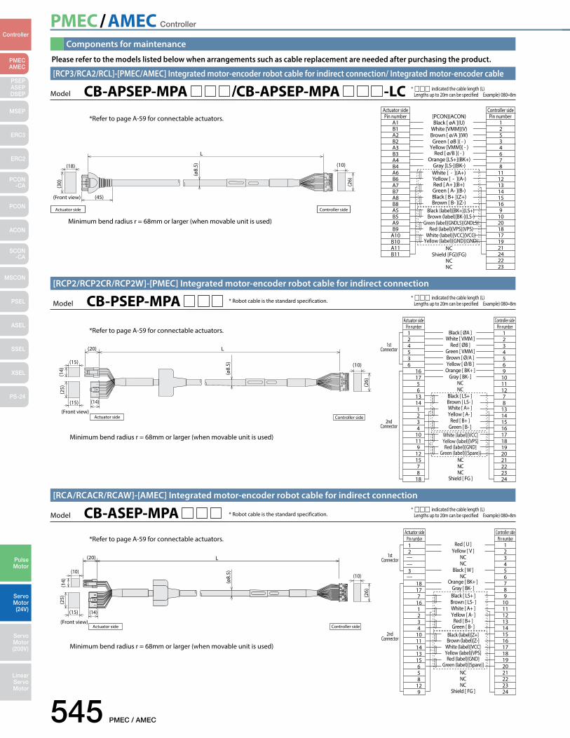
Components for maintenance
Please refer to the models listed below when arrangements such as cable replacement are needed after purchasing the product.
Model CB-PSEP-MPA [RCP2/RCP2CR/RCP2W]-[PMEC] Integrated motor-encoder robot cable for indirect connection
L
(Front view)
(15)
(ø8.
5)(15)
(25) (2
6)
(14)
(20)
(10)
(14)
Actuator side Controller side
Controller sideActuator side
Black [ ØA ]Pin number124536
161756
13141234
10119
121578
18
White [ VMM ]Red [ ØB ]
Green [ VMM ]Brown [ Ø/A ]Yellow [ Ø/B ]Orange [ BK+ ]
Gray [ BK- ]NCNC
Black [ LS+ ]Brown [ LS- ]White [ A+ ]Yellow [ A- ]
Red [ B+ ]Green [ B- ]
White (label)[VCC]Yellow (label)[VPS]Red (label)[GND]
Green (label)[(Spare)]NCNCNC
Shield [ FG ]
Pin number1234569
10111278
131415161718192021222324
1stConnector
2ndConnector
* ccc indicated the cable length (L) Lengths up to 20m can be specified Example) 080=8m
*Refer to page A-59 for connectable actuators.
* Robot cable is the standard specification.
Minimum bend radius r = 68mm or larger (when movable unit is used)
Model CB-ASEP-MPA [RCA/RCACR/RCAW]-[AMEC] Integrated motor-encoder robot cable for indirect connection
1stConnector
2ndConnector
Red [ U ]12
——
—3
18177
161234
1011141315658
129
Yellow [ V ]NCNC
Black [ W ]NC
Orange [ BK+ ]Gray [ BK- ]Black [ LS+ ]Brown [ LS- ]White [ A+ ]Yellow [ A- ]
Red [ B+ ]Green [ B- ]
Black (label)[Z+]Brown (label)[Z-]
White (label)[VCC]Yellow (label)[VPS]Red (label)[GND]
Green (label)[(Spare)]NCNCNC
Shield [ FG ]
123456789
101112131415161718192021222324
Controller sideActuator sidePin number Pin number
Actuator side Controller side(Front view)
(ø8.
5)
(20) L
(15)
(10)(10)
(14)
(25) (2
6)
(14)
* ccc indicated the cable length (L) Lengths up to 20m can be specified Example) 080=8m
*Refer to page A-59 for connectable actuators.
* Robot cable is the standard specification.
Minimum bend radius r = 68mm or larger (when movable unit is used)
L
Actuator side
(18) (10)
(45)
(30) (26)
(ø8.
5)(Front view)
NC
Black (label)[BK+](LS+)
White [ - ](A+)
[PCON](ACON)Actuator sidePin number
A1B1A2B2A3B3A4B4A6B6A7B7A8B8A5B5A9B9
A10B10A11B11
Controller sidePin number
12534678
1112131415169
102018171921242223
Black [ øA ](U)White [VMM](V)Brown [ ø/A ](W)Green [ øB ]( - )
Yellow [VMM]( - )Red [ ø/B ]( - )
Orange [LS+](BK+)Gray [LS-](BK-)
Yellow [ - ](A-)Red [ A+ ](B+)Green [ A- ](B-)Black [ B+ ](Z+)Brown [ B- ](Z-)
Brown (label)[BK-](LS-)Green (label)[GNDLS](GNDLS)
Red (label)[VPS](VPS)White (label)[VCC](VCC)
Yellow (label)[GND](GND)
Shield [FG](FG)NCNC
Controller side
* ccc indicated the cable length (L) Lengths up to 20m can be specified Example) 080=8m
[RCP3/RCA2/RCL]-[PMEC/AMEC] Integrated motor-encoder robot cable for indirect connection/ Integrated motor-encoder cable
Model CB-APSEP-MPA /CB-APSEP-MPA -LC
*Refer to page A-59 for connectable actuators.
Minimum bend radius r = 68mm or larger (when movable unit is used)
PMEC/AMEC Controller
PMEC / AMEC 546
PMECAMEC
Controller
Pulse Motor
Servo Motor (24V)
Servo Motor (200V)
LinearServo Motor
PSEP ASEPDSEP
MSEP
ERC3
ERC2
PCON-CA
PCON
ACON
SCON-CA
MSCON
PSEL
ASEL
SSEL
XSEL
PS-24
Black [ øA ]Pin number
A1B1A2B2A3B3A6B6A7B7A8B8A4B4A5B5A9B9
A10B10A11B11
White [ VMM ]Brown [ ø/A ]Green [ øB ]
Yellow [ VMM ]Red [ ø/B ]
Orange [ LS+ ]Gray [ LS- ]Red [ A+ ]
Green [ A- ]Black [ B+ ]Brown [ B- ]
NCNC
Black (label)[BK+]Brown (label)[BK-]
Green (label)[GNDLS]Red (label)[VPS]
White (label)[VCC]Yellow (label)[GND]
NCShield [ FG ](FG)
NCNC
Pin number12534678
13141516789
102018171921242223
Controller sideActuator side
Actuator side Controller side
(Front view)
(ø8.
5)
L
(18) (10)
(45)
(30) (26)
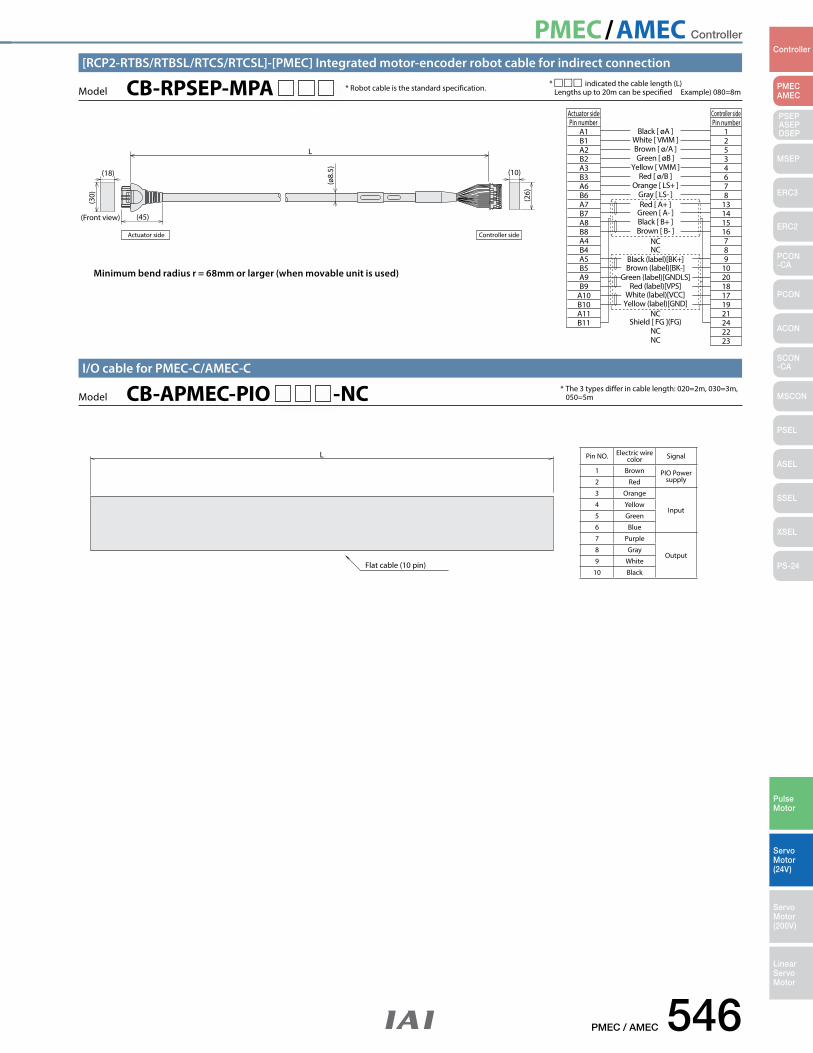
* Robot cable is the standard specification. * ccc indicated the cable length (L) Lengths up to 20m can be specified Example) 080=8m Model CB-RPSEP-MPA
[RCP2-RTBS/RTBSL/RTCS/RTCSL]-[PMEC] Integrated motor-encoder robot cable for indirect connection
Minimum bend radius r = 68mm or larger (when movable unit is used)
L
Flat cable (10 pin)
* The 3 types differ in cable length: 020=2m, 030=3m, 050=5mModel CB-APMEC-PIO -NC
I/O cable for PMEC-C/AMEC-C
Pin NO. Electric wire color Signal
1 Brown PIO Power supply2 Red
3 Orange
Input4 Yellow
5 Green
6 Blue
7 Purple
Output8 Gray
9 White
10 Black
PSEP/ASEP/DSEP Controller
547 PSEP / ASEP / DSEP
PMECAMEC
Controller
Pulse Motor
Servo Motor (24V)
Servo Motor (200V)
LinearServo Motor
PSEP ASEPDSEP
MSEP
ERC3
ERC2
PCON-CA
PCON
ACON
SCON-CA
MSCON
PSEL
ASEL
SSEL
XSEL
PS-24
When mounting the absolute battery unit, mount it below the SEP controller to prevent heat damage.
Signal ON
Signal OFF
Retracted
Extended
SEP controller
Absolute battery unit
Push force can be adjusted from 20 to 70% of the maximum push force.
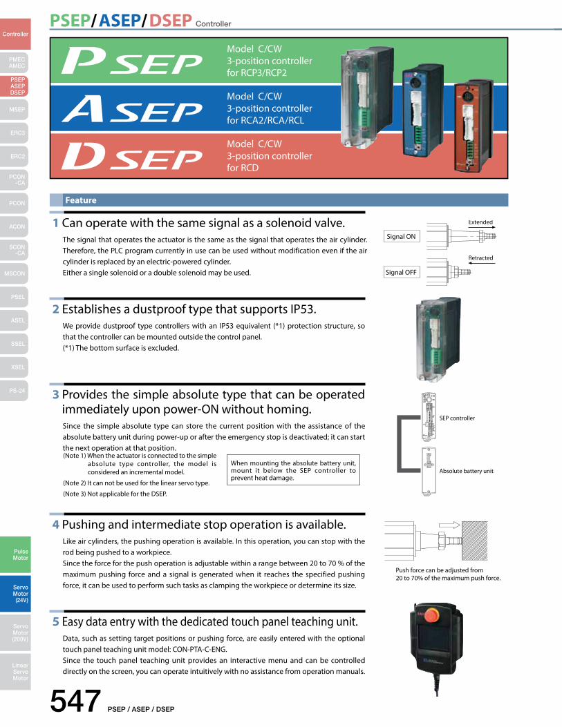
Model C/CW3-position controller for RCP3/RCP2
Model C/CW3-position controller for RCD
Model C/CW3-position controller for RCA2/RCA/RCL
Feature
1 Can operate with the same signal as a solenoid valve.
The signal that operates the actuator is the same as the signal that operates the air cylinder.Therefore, the PLC program currently in use can be used without modification even if the air cylinder is replaced by an electric-powered cylinder.Either a single solenoid or a double solenoid may be used.
2 Establishes a dustproof type that supports IP53.
We provide dustproof type controllers with an IP53 equivalent (*1) protection structure, so that the controller can be mounted outside the control panel.(*1) The bottom surface is excluded.
3 Provides the simple absolute type that can be operated immediately upon power-ON without homing. Since the simple absolute type can store the current position with the assistance of the absolute battery unit during power-up or after the emergency stop is deactivated; it can start the next operation at that position.
4 Pushing and intermediate stop operation is available.
Like air cylinders, the pushing operation is available. In this operation, you can stop with the rod being pushed to a workpiece.Since the force for the push operation is adjustable within a range between 20 to 70 % of the maximum pushing force and a signal is generated when it reaches the specified pushing force, it can be used to perform such tasks as clamping the workpiece or determine its size.
5 Easy data entry with the dedicated touch panel teaching unit.Data, such as setting target positions or pushing force, are easily entered with the optional touch panel teaching unit model: CON-PTA-C-ENG.Since the touch panel teaching unit provides an interactive menu and can be controlled directly on the screen, you can operate intuitively with no assistance from operation manuals.
(Note 1) When the actuator is connected to the simple absolute type controller, the model is considered an incremental model.
(Note 2) It can not be used for the linear servo type.
(Note 3) Not applicable for the DSEP.
PSEP/ASEP/DSEP Controller
PSEP / ASEP / DSEP 548
PMECAMEC
Controller
Pulse Motor
Servo Motor (24V)
Servo Motor (200V)
LinearServo Motor
PSEP ASEPDSEP
MSEP
ERC3
ERC2
PCON-CA
PCON
ACON
SCON-CA
MSCON
PSEL
ASEL
SSEL
XSEL
PS-24
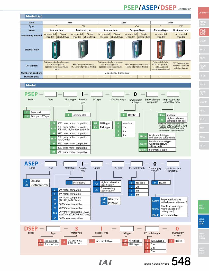
Model List
Series PSEP ASEP DSEP
Type C CW C CW C CW
Name Standard type Dustproof type Standard type Dustproof type Standard type Dustproof type
Positioning method Incremental encoder
Simple absolute type
Incremental encoder
Simple absolute type
Incremental encoder
Simple absolute type
Incremental encoder
Simple absolute type
Incremental encoder
Incremental encoder
External View
Description
Position controller, for pulse motors, specialized to 2 positions /
3 positions positioning and easier control
PSEP-C dustproof type with an IP53 equivalent protection structure
Position controller, for servo motors, specialized to 2 positions /
3 positions positioning and easier control
ASEP-C dustproof type with an IP53 equivalent protection structure
Position controller, for the RCD actuator, specialized to
2 positions / 3 positions positioning and easier control
DSEP-C dustproof type with an IP53 equivalent
protection structure
Number of positions 2 positions / 3 positions
Standard price — — — — — — — —− — —
DSEPSeries Type
3Motor type I/O type
IEncoder type I/O cable length
0Power supply
voltage
C Standard typeCW Dustproof type
NP NPN type PN PNP type
0 Without cable2 2m3 3m5 5m
0 DC24VI Incremental Type3 DC brushless 2.5W Motors
ASEPSeries
C Standard
CW Dustproof Type
I 0Type Option I/O type Power supply
voltageSimple absolute
compatibleMotor type Encoder
typeI/O cable length
I Incremental HA High-acceleration specification
LA Power-saving specification2 2W motor compatible
5 5W motor compatible
5S 5W motor compatible(SA2A,RA2A only)
10 10W motor compatible
20 20W motor compatible
20S 20W motor compatible (RCA2-SA4/TA5, RCA-RA3 only)
30 30W motor compatible
NP NPN type
PN PNP type
0 No cable
2 2m
3 3m
5 5m
0 DC24V
ABUM Simple absolute type (with absolute battery unit)
ABUMNSimple absolute type (without absolute battery unit)
(Blank) Incremental type
Model
PSEP I 0Series Type I/O type I/O cable length Power supply
voltageHigh accelerationcompatible model
Motor type Encoder type
Simple absolutecompatible
C Standard
CW Dustproof Type I Incremental 0 DC24V
NP NPN type
PN PNP type
20P 20 pulse motor compatible
20SP 20 pulse motor compatible RCP3-RA2 high-thrust type only)
28P 28 pulse motor compatible
28SP 28 pulse motor compatible (RA3C only)
35P 35 pulse motor compatible
42P 42 pulse motor compatible
56P 56 pulse motor compatible
0 No cable
2 2m
3 3m
5 5m
Blank Standard
H High acceleration compatible model
ABUM Simple absolute type (with absolute battery unit)
ABUMNSimple absolute type (without absolute battery unit)
(Blank) Incremental type
* Enter "H" when connecting with the RCP3-SA4C/SA5C/SA6C or RCP2 (RCP2CR)-SA5C/SA6C that are high acceleration compatible models.
PSEP/ASEP/DSEP Controller
549 PSEP / ASEP / DSEP
PMECAMEC
Controller
Pulse Motor
Servo Motor (24V)
Servo Motor (200V)
LinearServo Motor
PSEP ASEPDSEP
MSEP
ERC3
ERC2
PCON-CA
PCON
ACON
SCON-CA
MSCON
PSEL
ASEL
SSEL
XSEL
PS-24
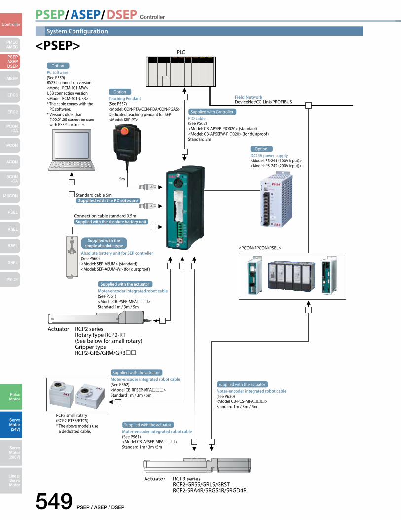
System Configuration
PLC
5m
PIO cable(See P562)<Model: CB-APSEP-PIO020> (standard)<Model: CB-APSEPW-PIO020> (for dustproof )Standard 2m
Supplied with Controller
Moter-encoder integrated robot cable(See P562)<Model CB-RPSEP-MPA>Standard 1m / 3m / 5m
Supplied with the actuator
Moter-encoder integrated robot cable(See P561)<Model CB-APSEP-MPA>Standard 1m / 3m /5m
Supplied with the actuator
Moter-encoder integrated robot cable(See P630)<Model CB-PCS-MPA>Standard 1m / 3m / 5m
Supplied with the actuator
Absolute battery unit for SEP controller (See P560)<Model: SEP-ABUM> (standard)<Model: SEP-ABUM-W> (for dustproof )
Supplied with the simple absolute type
Moter-encoder integrated robot cable(See P561)<Model CB-PSEP-MPA>Standard 1m / 3m / 5m
Supplied with the actuator
Actuator RCP2 series Rotary type RCP2-RT (See below for small rotary) Gripper type RCP2-GRS/GRM/GR3
RCP2 small rotary(RCP2-RTBS/RTCS)* The above models use a dedicated cable.
Actuator RCP3 series RCP2-GRSS/GRLS/GRST RCP2-SRA4R/SRGS4R/SRGD4R
<PCON/RPCON/PSEL>
Field NetworkDeviceNet/CC-Link/PROFIBUS
PC software(See P559)RS232 connection version<Model: RCM-101-MW>USB connection version<Model: RCM-101-USB>* The cable comes with the PC software.* Versions older than 7.00.01.00 cannot be used with PSEP controller.
Option
Teaching Pendant(See P557)<Model: CON-PTA/CON-PDA/CON-PGAS>Dedicated teaching pendant for SEP<Model: SEP-PT>
Option
DC24V power supply<Model: PS-241 (100V input)><Model: PS-242 (200V input)>
Option
Supplied with the PC softwareStandard cable 5m
Supplied with the absolute battery unitConnection cable standard 0.5m
<PSEP>
PSEP/ASEP/DSEP Controller
PSEP / ASEP / DSEP 550
PMECAMEC
Controller
Pulse Motor
Servo Motor (24V)
Servo Motor (200V)
LinearServo Motor
PSEP ASEPDSEP
MSEP
ERC3
ERC2
PCON-CA
PCON
ACON
SCON-CA
MSCON
PSEL
ASEL
SSEL
XSEL
PS-24
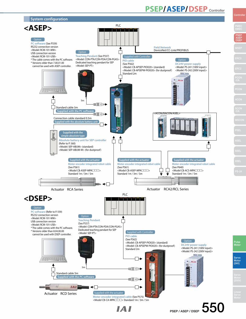
System configuration
PLC
5m
PLC
5m
PIO cable(See P562)<Model: CB-APSEP-PIO020> (standard)<Model: CB-APSEPW-PIO020> (for dustproof )Standard 2m
Supplied with Controller
PIO cable(See P562)<Model: CB-APSEP-PIO020> (standard)<Model: CB-APSEPW-PIO020> (for dustproof )Standard 2m
Supplied with Controller
Moter-encoder integrated cable (See P575)<Model CB-CA-MPA> Standard 1m / 3m / 5m
Supplied with the actuator
Absolute battery unit for SEP controller (Refer to P. 560)<Model: SEP-ABUM> (standard)<Model: SEP-ABUM-W> (for dustproof )
Supplied with the simple absolute type
Moter-encoder integrated robot cable(See P561)<Model CB-ASEP-MPA>Standard 1m / 3m / 5m
Supplied with the actuatorMoter-encoder integrated robot cable(See P561)<Model CB-ASEP-MPA>Standard 1m / 3m / 5m
Supplied with the actuatorMoter-encoder integrated robot cable(See P640)<Model CB-ACS-MPA>Standard 1m / 3m / 5m
Supplied with the actuator
Actuator RCA2/RCL SeriesActuator RCA Series
Actuator RCD Series
<ACON/RACON/ASEL>
Field NetworkDeviceNet/CC-Link/PROFIBUS
PC software (See P559)RS232 connection version<Model: RCM-101-MW>USB connection version<Model: RCM-101-USB>* The cable comes with the PC software.* Versions older than 7.00.01.00 cannot be used with ASEP controller.
Option
PC software (Refer to P. 559)RS232 connection version<Model: RCM-101-MW>USB connection version<Model: RCM-101-USB>* The cable comes with the PC software.* Versions older than 8.04.00.00 cannot be used with DSEP controller.
Option
Teaching Pendant (See P557)<Model: CON-PTA/CON-PDA/CON-PGAS>Dedicated teaching pendant for SEP<Model: SEP-PT>
Option
Teaching Pendant(See P557)<Model: CON-PTA/CON-PDA/CON-PGAS>Dedicated teaching pendant for SEP<Model: SEP-PT>
Option
DC24V power supply<Model: PS-241 (100V input)><Model: PS-242 (200V input)>
Option
DC24V power supply<Model: PS-241 (100V input)><Model: PS-242 (200V input)>
Option
Supplied with the PC softwareStandard cable 5m
Supplied with the PC softwareStandard cable 5m
Supplied with the absolute battery unitConnection cable standard 0.5m
<ASEP>
<DSEP>
PSEP/ASEP/DSEP Controller
551 PSEP / ASEP / DSEP
PMECAMEC
Controller
Pulse Motor
Servo Motor (24V)
Servo Motor (200V)
LinearServo Motor
PSEP ASEPDSEP
MSEP
ERC3
ERC2
PCON-CA
PCON
ACON
SCON-CA
MSCON
PSEL
ASEL
SSEL
XSEL
PS-24
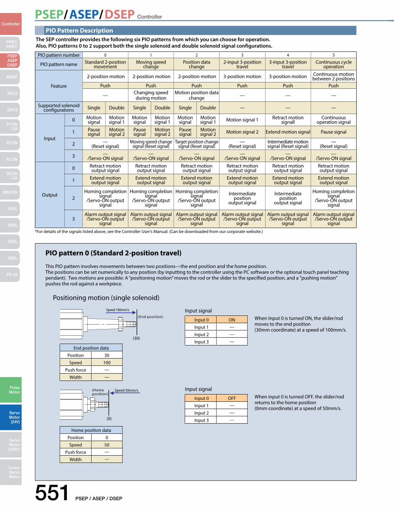
PIO pattern number 0 1 2 3 4 5
PIO pattern name Standard 2-position movement
Moving speed change
Position data change
2-input 3-position travel
3-input 3-position travel
Continuous cycle operation
Feature
2-position motion 2-position motion 2-position motion 3-position motion 3-position motion Continuous motion between 2 positions
Push Push Push Push Push Push
— Changing speed during motion
Motion position data change — — —
Supported solenoid configurations Single Double Single Double Single Double — — —
Input
0 Motion signal
Motion signal 1
Motion signal
Motion signal 1
Motion signal
Motion signal 1 Motion signal 1 Retract motion
signallContinuous
operation signal
1 Pause signal
Motion signal 2
Pause signal
Motion signal 2
Pause signal
Motion signal 2 Motion signal 2 Extend motion signal Pause signal
2 —(Reset signal)
Moving speed change signal (Reset signal)
Target position change signal (Reset signal)
—(Reset signal)
Intermediate motion signal (Reset signal)
—(Reset signal)
3 —/Servo-ON signal
—/Servo-ON signal
—/Servo-ON signal
—/Servo-ON signal
—/Servo-ON signal
—/Servo-ON signal
Output
0 Retract motion output signal
Retract motion output signal
Retract motion output signal
Retract motion output signal
Retract motion output signal
Retract motion output signal
1 Extend motion output signal
Extend motion output signal
Extend motion output signal
Extend motion output signal
Extend motion output signal
Extend motion output signal
2Homing completion
signal/Servo-ON output
signal
Homing completion signal
/Servo-ON output signal
Homing completion signal
/Servo-ON output signal
Intermediate position
output signal
Intermediate position
output signal
Homing completion signal
/Servo-ON output signal
3Alarm output signal /Servo-ON output
signal
Alarm output signal /Servo-ON output
signal
Alarm output signal /Servo-ON output
signal
Alarm output signal /Servo-ON output
signal
Alarm output signal /Servo-ON output
signal
Alarm output signal /Servo-ON output
signal
PIO Pattern Description
*For details of the signals listed above, see the Controller User’s Manual. (Can be downloaded from our corporate website.)
The SEP controller provides the following six PIO patterns from which you can choose for operation.Also, PIO patterns 0 to 2 support both the single solenoid and double solenoid signal configurations.
(End position)
(0)
(30)
(Home position)
Speed 100mm/s
Speed 50mm/s
PIO pattern 0 (Standard 2-position travel)
This PIO pattern involves movements between two positions—the end position and the home position.The positions can be set numerically to any position (by inputting to the controller using the PC software or the optional touch panel teaching pendant). Two motions are possible: A “positioning motion” moves the rod or the slider to the specified position, and a "pushing motion" pushes the rod against a workpiece.
Positioning motion (single solenoid)
End position data
Position 30
Speed 100
Push force —
Width —
Input 0 ON
Input 1 —
Input 2 —
Input 3 —
Input 0 OFF
Input 1 —
Input 2 —
Input 3 —
Home position data
Position 0
Speed 50
Push force —
Width —
When Input 0 is turned ON, the slider/rod moves to the end position (30mm coordinate) at a speed of 100mm/s.
When input 0 is turned OFF, the slider/rod returns to the home position (0mm coordinate) at a speed of 50mm/s.
Input signal
Input signal
PSEP/ASEP/DSEP Controller
PSEP / ASEP / DSEP 552
PMECAMEC
Controller
Pulse Motor
Servo Motor (24V)
Servo Motor (200V)
LinearServo Motor
PSEP ASEPDSEP
MSEP
ERC3
ERC2
PCON-CA
PCON
ACON
SCON-CA
MSCON
PSEL
ASEL
SSEL
XSEL
PS-24
(End position)
(End position)
(End position)
(30)
(0)
(20) (30)
(20) (30)
(Home position)
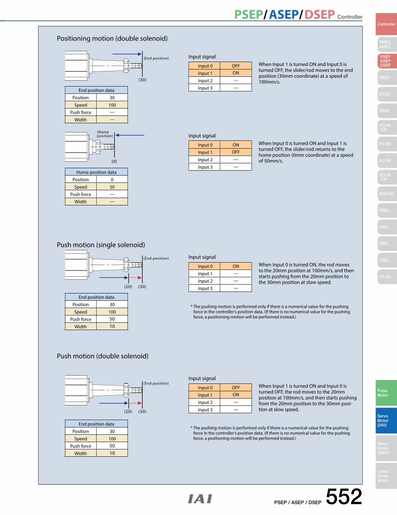
End position data
Position 30
Speed 100
Push force —
Width —
End position data
Position 30
Speed 100
Push force 50Width 10
End position data
Position 30
Speed 100
Push force 50Width 10
Positioning motion (double solenoid)
Push motion (single solenoid)
Push motion (double solenoid)
* The pushing motion is performed only if there is a numerical value for the pushing force in the controller's position data. (If there is no numerical value for the pushing force, a positioning motion will be performed instead.)
* The pushing motion is performed only if there is a numerical value for the pushing force in the controller's position data. (If there is no numerical value for the pushing force, a positioning motion will be performed instead.)
Home position data
Position 0
Speed 50
Push force —
Width —
Input 0 OFF
Input 1 ON
Input 2 —
Input 3 —
Input 0 ON
Input 1 OFF
Input 2 —
Input 3 —
Input 0 ON
Input 1 —
Input 2 —
Input 3 —
Input 0 OFF
Input 1 ON
Input 2 —
Input 3 —
When Input 1 is turned ON and Input 0 is turned OFF, the slider/rod moves to the end position (30mm coordinate) at a speed of 100mm/s.
When Input 0 is turned ON and Input 1 is turned OFF, the slider/rod returns to the home position (0mm coordinate) at a speed of 50mm/s.
When Input 0 is turned ON, the rod moves to the 20mm position at 100mm/s, and then starts pushing from the 20mm position to the 30mm position at slow speed.
When Input 1 is turned ON and Input 0 is turned OFF, the rod moves to the 20mm position at 100mm/s, and then starts pushing from the 20mm position to the 30mm posi-tion at slow speed.
Input signal
Input signal
Input signal
Input signal
PSEP/ASEP/DSEP Controller
553 PSEP / ASEP / DSEP
PMECAMEC
Controller
Pulse Motor
Servo Motor (24V)
Servo Motor (200V)
LinearServo Motor
PSEP ASEPDSEP
MSEP
ERC3
ERC2
PCON-CA
PCON
ACON
SCON-CA
MSCON
PSEL
ASEL
SSEL
XSEL
PS-24
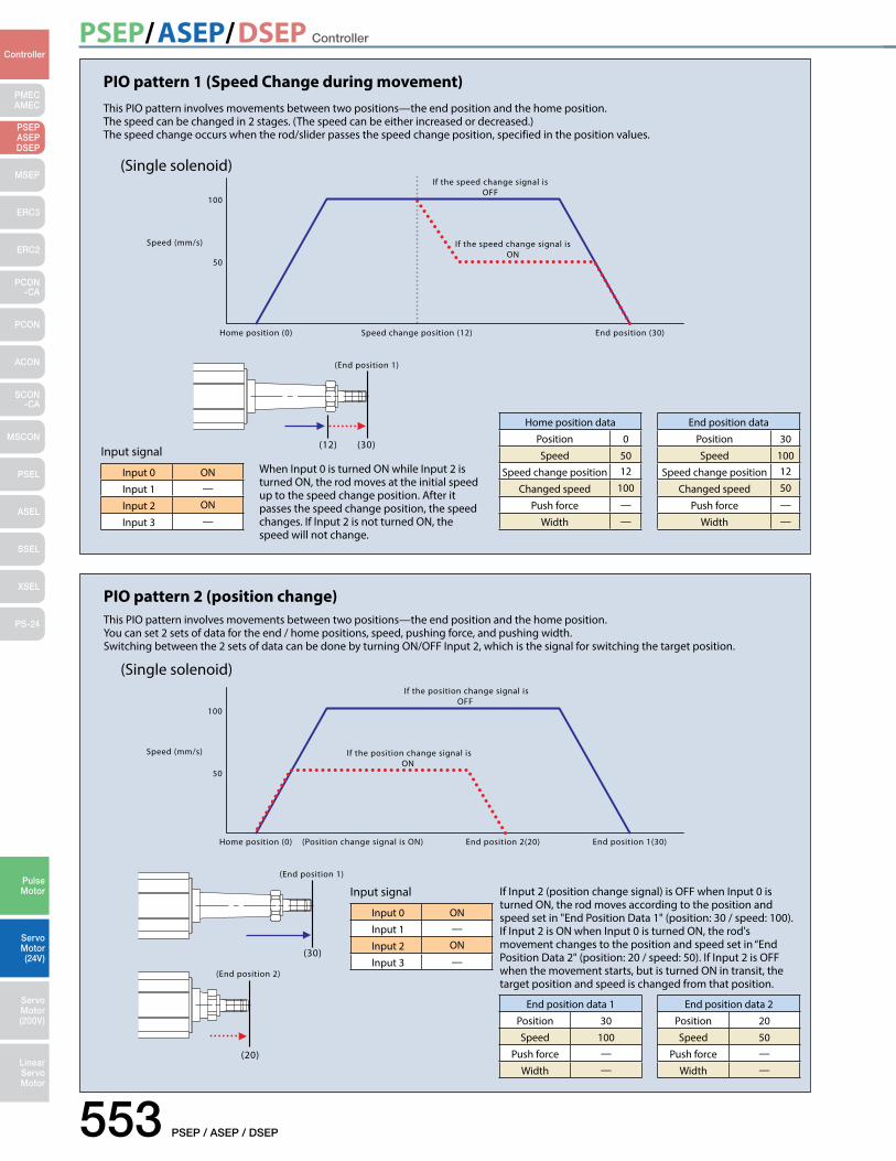
PIO pattern 1 (Speed Change during movement) This PIO pattern involves movements between two positions—the end position and the home position.The speed can be changed in 2 stages. (The speed can be either increased or decreased.)The speed change occurs when the rod/slider passes the speed change position, specified in the position values.
(Single solenoid)
Input 0 ON
Input 1 —
Input 2 ON
Input 3 —
Home position data
Position 0
Speed 50
Speed change position 12
Changed speed 100
Push force —
Width —
End position data
Position 30
Speed 100
Speed change position 12
Changed speed 50
Push force —
Width —
When Input 0 is turned ON while Input 2 is turned ON, the rod moves at the initial speed up to the speed change position. After it passes the speed change position, the speed changes. If Input 2 is not turned ON, the speed will not change.
Input signal
(End position 1)
Home position (0) End position (30)
50
100
Speed (mm/s)
Speed change position (12)
If the speed change signal is OFF
If the speed change signal is ON
(12) (30)
PIO pattern 2 (position change) This PIO pattern involves movements between two positions—the end position and the home position.You can set 2 sets of data for the end / home positions, speed, pushing force, and pushing width.Switching between the 2 sets of data can be done by turning ON/OFF Input 2, which is the signal for switching the target position.
(Single solenoid)
(End position 1)
End position 2(20)
Speed (mm/s)
(Position change signal is ON)
(End position 2)
If the position change signal isOFF
If the position change signal isON
50
100
Home position (0) End position 1(30)
(20)
(30)
End position data 1
Position 30
Speed 100
Push force —
Width —
End position data 2
Position 20
Speed 50
Push force —
Width —
If Input 2 (position change signal) is OFF when Input 0 is turned ON, the rod moves according to the position and speed set in "End Position Data 1" (position: 30 / speed: 100).If Input 2 is ON when Input 0 is turned ON, the rod's movement changes to the position and speed set in “End Position Data 2" (position: 20 / speed: 50). If Input 2 is OFF when the movement starts, but is turned ON in transit, the target position and speed is changed from that position.
Input 0 ON
Input 1 —
Input 2 ON
Input 3 —
Input signal
PSEP/ASEP/DSEP Controller
PSEP / ASEP / DSEP 554
PMECAMEC
Controller
Pulse Motor
Servo Motor (24V)
Servo Motor (200V)
LinearServo Motor
PSEP ASEPDSEP
MSEP
ERC3
ERC2
PCON-CA
PCON
ACON
SCON-CA
MSCON
PSEL
ASEL
SSEL
XSEL
PS-24
PIO pattern 3 (2-input 3-position travel) This PIO pattern involves movements between 3 positions—the end position, the home position, and an intermediate position.Changing between the positions is done by a combination of 2 signals, Input 0 and Input 1.
Positioning motion
Input 0 ON
Input 1 OFF
Input 2 —
Input 3 —
Input signalWhen only Input 0 is turned ON, the rod moves to the home position at the specified speed.
Input 0 ON
Input 1 ON
Input 2 —
Input 3 —
Input signalWhen Input 0 and Input 1 are both turned ON, the rod moves to the intermediate position at the specified speed.
Input 0 OFF
Input 1 ON
Input 2 —
Input 3 —
When only Input 1 is turned ON, the rod moves to the end position at the specified speed.
Input signal
(End position)
(Intermediate position)
(30)
(0)
(10)
(Home position)
PIO pattern 4 (3-input 3-position travel) This PIO pattern involves movements between 3 positions—the end position, the home position, and an intermediate position.Changing between positions is done by three signals—Input 0, Input 1 and Input 2, which are commanded to move to the home, end and intermediate positions, respectively.
Positioning motion
Input 0 ON
Input 1 OFF
Input 2 OFF
Input 3 —
Input signalWhen Input 0 is turned ON, the rod moves to the home position at the specified speed.
Input 0 OFF
Input 1 OFF
Input 2 ON
Input 3 —
Input signalWhen Input 2 is turned ON, the rod moves to the intermediate position at the specified speed.
Input 0 OFF
Input 1 ON
Input 2 OFF
Input 3 —
When Input 1 is turned ON, the rod moves to the end position at the specified speed.
Input signal(End position)
(Intermediate position)
(30)
(0)
(10)
(Home position)
PIO pattern 5 (continuous cycle operation) This PIO pattern involves continuous cycling between 2 positions—the end and home positions.When Input 0 (continuous operation signal) is turned ON, the rod continuously moves between the specified 2 positions.If Input 0 is turned OFF while in motion, it stops after reaching the current destination.
Positioning motion
Input 0 ON
Input 1 —
Input 2 —
Input 3 —
Input signalWhen Input 0 is turned ON,the rod moves continuously between the end and home positions at the specified speed.
(0) (20)
(Home position)
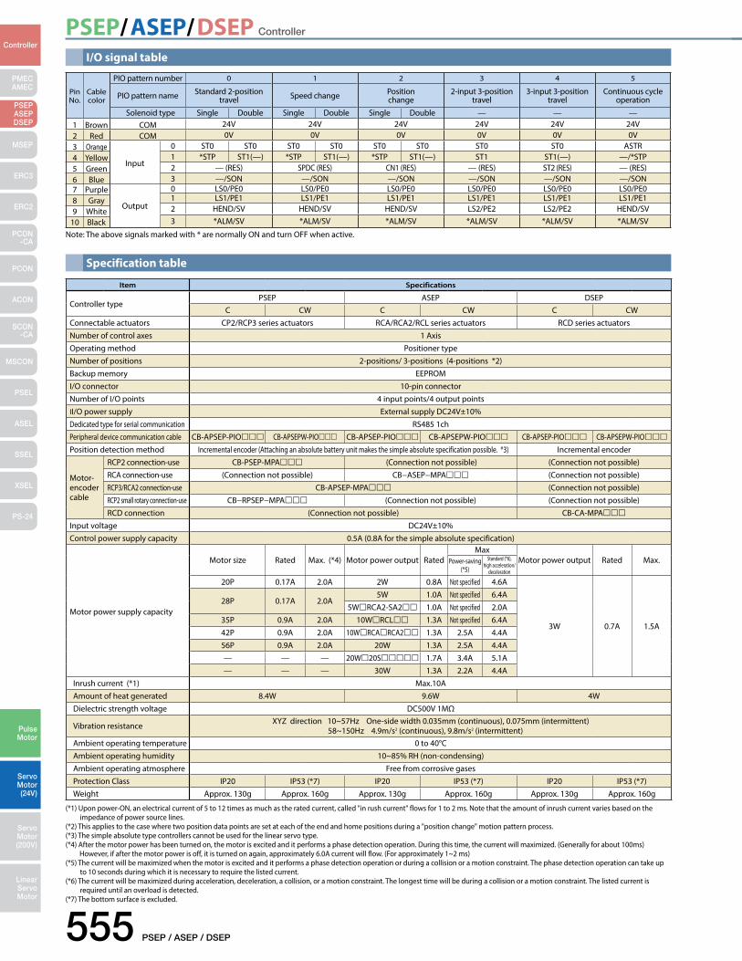
PSEP/ASEP/DSEP Controller
555 PSEP / ASEP / DSEP
PMECAMEC
Controller
Pulse Motor
Servo Motor (24V)
Servo Motor (200V)
LinearServo Motor
PSEP ASEPDSEP
MSEP
ERC3
ERC2
PCON-CA
PCON
ACON
SCON-CA
MSCON
PSEL
ASEL
SSEL
XSEL
PS-24
I/O signal table
Pin No.
Cable color
PIO pattern number 0 1 2 3 4 5
PIO pattern name Standard 2-position travel Speed change Position
change2-input 3-position
travel3-input 3-position
travelContinuous cycle
operation
Solenoid type Single Double Single Double Single Double — — —1 Brown COM 24V 24V 24V 24V 24V 24V2 Red COM 0V 0V 0V 0V 0V 0V3 Orange
Input
0 ST0 ST0 ST0 ST0 ST0 ST0 ST0 ST0 ASTR4 Yellow 1 *STP ST1(—) *STP ST1(—) *STP ST1(—) ST1 ST1(—) —/*STP5 Green 2 — (RES) SPDC (RES) CN1 (RES) — (RES) ST2 (RES) — (RES)6 Blue 3 —/SON —/SON —/SON —/SON —/SON —/SON7 Purple
Output
0 LS0/PE0 LS0/PE0 LS0/PE0 LS0/PE0 LS0/PE0 LS0/PE01 LS1/PE1 LS1/PE1 LS1/PE1 LS1/PE1 LS1/PE1 LS1/PE18 Gray2 HEND/SV HEND/SV HEND/SV LS2/PE2 LS2/PE2 HEND/SV9 White3 *ALM/SV *ALM/SV *ALM/SV *ALM/SV *ALM/SV *ALM/SV10 Black
Note: The above signals marked with * are normally ON and turn OFF when active.
Specification table
(*1) Upon power-ON, an electrical current of 5 to 12 times as much as the rated current, called "in rush current" flows for 1 to 2 ms. Note that the amount of inrush current varies based on the impedance of power source lines.
(*2) This applies to the case where two position data points are set at each of the end and home positions during a "position change" motion pattern process.(*3) The simple absolute type controllers cannot be used for the linear servo type.(*4) After the motor power has been turned on, the motor is excited and it performs a phase detection operation. During this time, the current will maximized. (Generally for about 100ms) However, if after the motor power is off, it is turned on again, approximately 6.0A current will flow. (For approximately 1~2 ms)(*5) The current will be maximized when the motor is excited and it performs a phase detection operation or during a collision or a motion constraint. The phase detection operation can take up
to 10 seconds during which it is necessary to require the listed current.(*6) The current will be maximized during acceleration, deceleration, a collision, or a motion constraint. The longest time will be during a collision or a motion constraint. The listed current is
required until an overload is detected.(*7) The bottom surface is excluded.
Item Specifications
Controller typePSEP ASEP DSEP
C CW C CW C CWConnectable actuators CP2/RCP3 series actuators RCA/RCA2/RCL series actuators RCD series actuatorsNumber of control axes 1 Axis Operating method Positioner typeNumber of positions 2-positions/ 3-positions (4-positions *2)Backup memory EEPROMI/O connector 10-pin connectorNumber of I/O points 4 input points/4 output pointsII/O power supply External supply DC24V±10%Dedicated type for serial communication RS485 1chPeripheral device communication cable CB-APSEP-PIO CB-APSEPW-PIO CB-APSEP-PIO CB-APSEPW-PIO CB-APSEP-PIO CB-APSEPW-PIOPosition detection method Incremental encoder (Attaching an absolute battery unit makes the simple absolute specification possible. *3) Incremental encoder
Motor-encoder cable
RCP2 connection-use CB-PSEP-MPA (Connection not possible) (Connection not possible)RCA connection-use (Connection not possible) CB−ASEP−MPA (Connection not possible)RCP3/RCA2 connection-use CB-APSEP-MPA (Connection not possible)RCP2 small rotary connection-use CB−RPSEP−MPA (Connection not possible) (Connection not possible)RCD connection (Connection not possible) CB-CA-MPA
Input voltage DC24V±10%Control power supply capacity 0.5A (0.8A for the simple absolute specification)
Motor power supply capacity
Motor size Rated Max. (*4) Motor power output RatedMax
Motor power output Rated Max.Power-saving (*5)
Standard (*6), high acceleration/
deceleration
20P 0.17A 2.0A 2W 0.8A Not specified 4.6A
3W 0.7A 1.5A
28P 0.17A 2.0A5W 1.0A Not specified 6.4A
5WRCA2-SA2 1.0A Not specified 2.0A35P 0.9A 2.0A 10WRCL 1.3A Not specified 6.4A42P 0.9A 2.0A 10WRCARCA2 1.3A 2.5A 4.4A56P 0.9A 2.0A 20W 1.3A 2.5A 4.4A— — — 20W20S 1.7A 3.4A 5.1A— — — 30W 1.3A 2.2A 4.4A
Inrush current (*1) Max.10AAmount of heat generated 8.4W 9.6W 4WDielectric strength voltage DC500V 1MΩ
Vibration resistance XYZ direction 10~57Hz One-side width 0.035mm (continuous), 0.075mm (intermittent) 58~150Hz 4.9m/s2 (continuous), 9.8m/s2 (intermittent)
Ambient operating temperature 0 to 40°CAmbient operating humidity 10~85% RH (non-condensing)Ambient operating atmosphere Free from corrosive gasesProtection Class IP20 IP53 (*7) IP20 IP53 (*7) IP20 IP53 (*7)Weight Approx. 130g Approx. 160g Approx. 130g Approx. 160g Approx. 130g Approx. 160g

PSEP/ASEP/DSEP Controller
PSEP / ASEP / DSEP 556
PMECAMEC
Controller
Pulse Motor
Servo Motor (24V)
Servo Motor (200V)
LinearServo Motor
PSEP ASEPDSEP
MSEP
ERC3
ERC2
PCON-CA
PCON
ACON
SCON-CA
MSCON
PSEL
ASEL
SSEL
XSEL
PS-24
35.4
(35m
m D
IN ra
il w
idth
)
(50m
m fr
om th
e ce
nter
of t
he D
IN ra
il)
(6) 66.2
30
72.2
110
100
(10) 5
DIN can be narrowed by 5mm
Standard type
100
107
112
(10) 5
34
(6) 99.7105.7
DIN can be narrowed by 5mm
(50m
m fr
om th
e ce
nter
of t
he D
IN ra
il)
35.4
(35m
m D
IN ra
il w
idth
)
Dustproof type
Names
External dimensions
PSEP, ASEP, DSEP Incremental type
Status LED(for SV, ALM, EMG)
Actuator modelnumber sticker
FG connector
Power supply connector
Motor-encodercable connector
PIO connector
SIO connector
PSEP, ASEP Simple absolute type LED for ABS
SIO connector
PIO connector
Battery connector
FG connector
Status LED(for SV, ALM, EMG)
Motor-encoder cable connector
Power supply connector
Actuator model number sticker
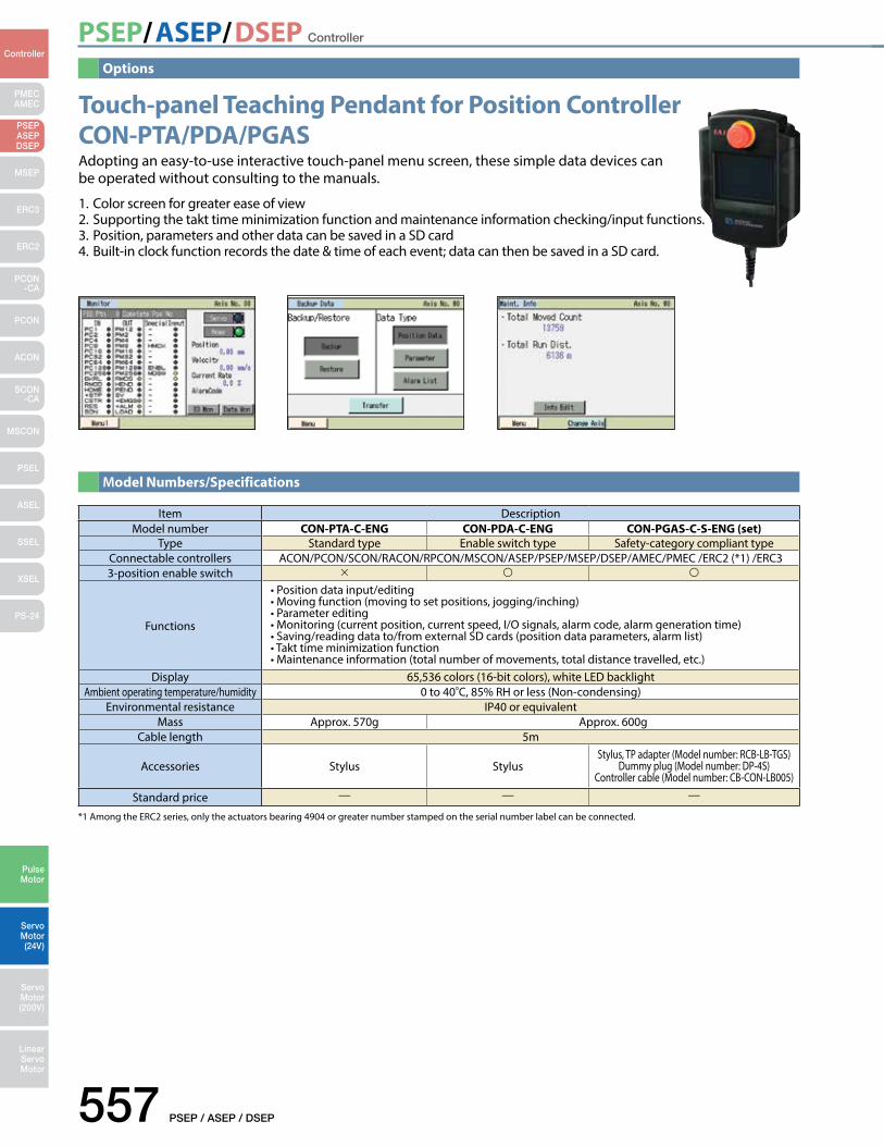
PSEP/ASEP/DSEP Controller
557 PSEP / ASEP / DSEP
PMECAMEC
Controller
Pulse Motor
Servo Motor (24V)
Servo Motor (200V)
LinearServo Motor
PSEP ASEPDSEP
MSEP
ERC3
ERC2
PCON-CA
PCON
ACON
SCON-CA
MSCON
PSEL
ASEL
SSEL
XSEL
PS-24
*1 Among the ERC2 series, only the actuators bearing 4904 or greater number stamped on the serial number label can be connected.
Touch-panel Teaching Pendant for Position Controller CON-PTA/PDA/PGAS Adopting an easy-to-use interactive touch-panel menu screen, these simple data devices can be operated without consulting to the manuals.
1. Color screen for greater ease of view2. Supporting the takt time minimization function and maintenance information checking/input functions.3. Position, parameters and other data can be saved in a SD card4. Built-in clock function records the date & time of each event; data can then be saved in a SD card.
Item DescriptionModel number CON-PTA-C-ENG CON-PDA-C-ENG CON-PGAS-C-S-ENG (set)
Type Standard type Enable switch type Safety-category compliant typeConnectable controllers ACON/PCON/SCON/RACON/RPCON/MSCON/ASEP/PSEP/MSEP/DSEP/AMEC/PMEC /ERC2 (*1) /ERC33-position enable switch
Functions
•Positiondatainput/editing•Movingfunction(movingtosetpositions,jogging/inching)•Parameterediting•Monitoring(currentposition,currentspeed,I/Osignals,alarmcode,alarmgenerationtime)•Saving/readingdatato/fromexternalSDcards(positiondataparameters,alarmlist)•Takttimeminimizationfunction•Maintenanceinformation(totalnumberofmovements,totaldistancetravelled,etc.)
Display 65,536 colors (16-bit colors), white LED backlightAmbient operating temperature/humidity 0 to 40C, 85% RH or less (Non-condensing)
Environmental resistance IP40 or equivalentMass Approx. 570g Approx. 600g
Cable length 5m
Accessories Stylus StylusStylus, TP adapter (Model number: RCB-LB-TGS)
Dummy plug (Model number: DP-4S)Controller cable (Model number: CB-CON-LB005)
Standard price — — —
Options
Model Numbers/Specifications

PSEP/ASEP/DSEP Controller
PSEP / ASEP / DSEP 558
PMECAMEC
Controller
Pulse Motor
Servo Motor (24V)
Servo Motor (200V)
LinearServo Motor
PSEP ASEPDSEP
MSEP
ERC3
ERC2
PCON-CA
PCON
ACON
SCON-CA
MSCON
PSEL
ASEL
SSEL
XSEL
PS-24
CON-PGAS-C
424
13292.1
180
( 50)
5m
98
1410
CON-PTA-CCON-PDA-C
Wall mount hook
Model number / Serial number label
Strap anchor
StylusEmergency stop button
Control panel
* Please note that the CON-PGAS-C has a controller insertion connector that is dierent from the other models.
Controller insertion connector
Enable switch
CON-PT label
Name of each part/Outer dimensions
Wiring Diagram of CON-PGAS-C-S
Option
•Strap MODELSTR-1
ACONPCON
ROBONETPSEP ASEP
SCON
DSEP CON-PGAS -C
0.5m
5m
Controller connection cable CB-CON-LB005
TP adapter RCB-LB-TG
Safety circuit
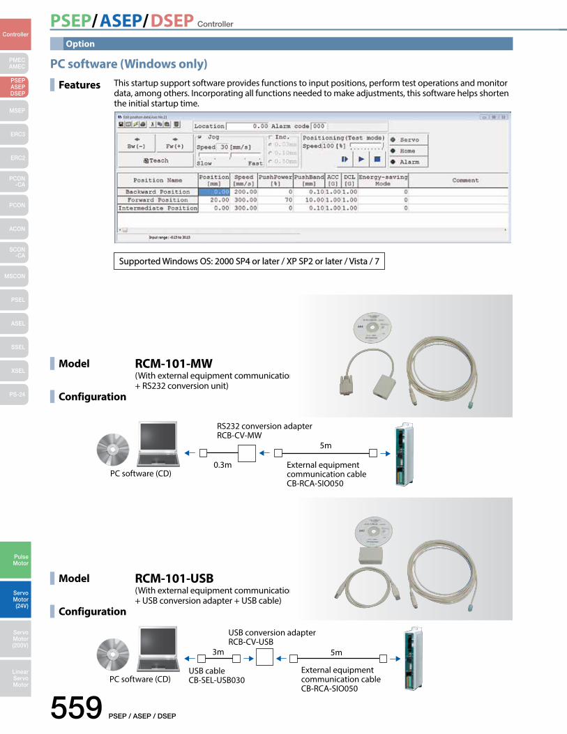
PSEP/ASEP/DSEP Controller
559 PSEP / ASEP / DSEP
PMECAMEC
Controller
Pulse Motor
Servo Motor (24V)
Servo Motor (200V)
LinearServo Motor
PSEP ASEPDSEP
MSEP
ERC3
ERC2
PCON-CA
PCON
ACON
SCON-CA
MSCON
PSEL
ASEL
SSEL
XSEL
PS-24
Option
PC software (Windows only)
Features This startup support software provides functions to input positions, perform test operations and monitor data, among others. Incorporating all functions needed to make adjustments, this software helps shortenthe initial startup time.
Supported Windows OS: 2000 SP4 or later / XP SP2 or later / Vista / 7
Model
Configuration
RCM-101-MW (With external equipment communication cable + RS232 conversion unit)
RS232 conversion adapter RCB-CV-MW
PC software (CD)0.3m
5m
External equipment communication cable CB-RCA-SIO050
Model
Configuration
RCM-101-USB (With external equipment communication cable + USB conversion adapter + USB cable)
PC software (CD)
5m
USB conversion adapter RCB-CV-USB
USB cableCB-SEL-USB030
3m
External equipment communication cable CB-RCA-SIO050
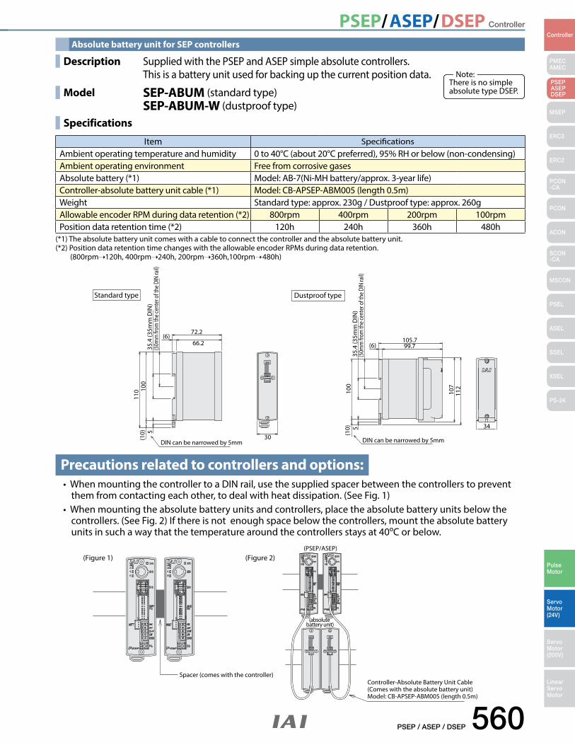
PSEP/ASEP/DSEP Controller
PSEP / ASEP / DSEP 560
PMECAMEC
Controller
Pulse Motor
Servo Motor (24V)
Servo Motor (200V)
LinearServo Motor
PSEP ASEPDSEP
MSEP
ERC3
ERC2
PCON-CA
PCON
ACON
SCON-CA
MSCON
PSEL
ASEL
SSEL
XSEL
PS-24
Dustproof type
35.4
(35m
m D
IN)
(6)105.799.7
107
112
100
(10) 5 34
(50m
m fr
om th
e ce
nter
of t
he D
IN ra
il)
DIN can be narrowed by 5mm
Spacer (comes with the controller)
(Figure 1) (PSEP/ASEP)
(absolute battery unit)
Controller-Absolute Battery Unit Cable(Comes with the absolute battery unit)Model: CB-APSEP-ABM005 (length 0.5m)
(Figure 2)
35.4
(35m
m D
IN)
72.2
66.2(6)
110 10
0(1
0) 5
30
(50m
m fr
om th
e ce
nter
of t
he D
IN ra
il)
DIN can be narrowed by 5mm
Standard type
Absolute battery unit for SEP controllers
(*1) The absolute battery unit comes with a cable to connect the controller and the absolute battery unit.(*2) Position data retention time changes with the allowable encoder RPMs during data retention.
(800rpm 120h, 400rpm 240h, 200rpm 360h,100rpm 480h)
Precautions related to controllers and options:•WhenmountingthecontrollertoaDINrail,usethesuppliedspacerbetweenthecontrollerstoprevent
them from contacting each other, to deal with heat dissipation. (See Fig. 1)•Whenmountingtheabsolutebatteryunitsandcontrollers,placetheabsolutebatteryunitsbelowthe
controllers. (See Fig. 2) If there is not enough space below the controllers, mount the absolute battery units in such a way that the temperature around the controllers stays at 40ºC or below.
Item SpecificationsAmbient operating temperature and humidity 0 to 40°C (about 20°C preferred), 95% RH or below (non-condensing) Ambient operating environment Free from corrosive gasesAbsolute battery (*1) Model: AB-7(Ni-MH battery/approx. 3-year life)Controller-absolute battery unit cable (*1) Model: CB-APSEP-ABM005 (length 0.5m) Weight Standard type: approx. 230g / Dustproof type: approx. 260g Allowable encoder RPM during data retention (*2) 800rpm 400rpm 200rpm 100rpmPosition data retention time (*2) 120h 240h 360h 480h
There is no simple absolute type DSEP.
Note: Description Supplied with the PSEP and ASEP simple absolute controllers.
This is a battery unit used for backing up the current position data.
Model SEP-ABUM (standard type) SEP-ABUM-W (dustproof type)
Specifications
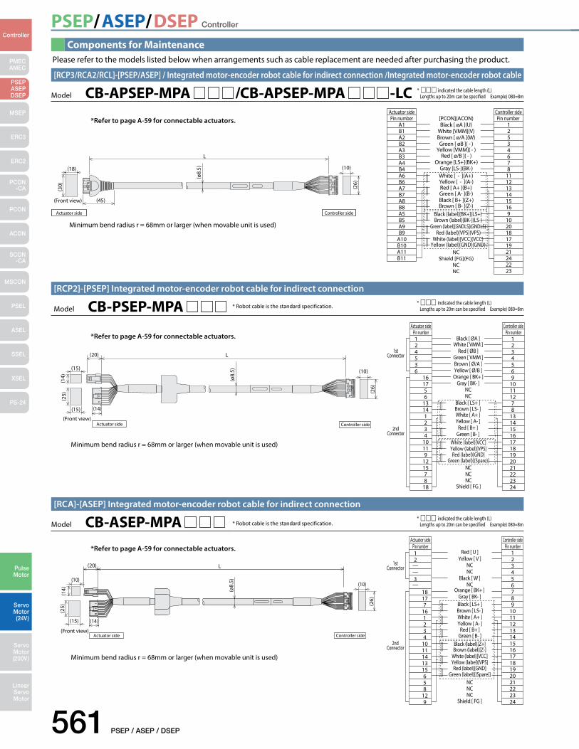
PSEP/ASEP/DSEP Controller
561 PSEP / ASEP / DSEP
PMECAMEC
Controller
Pulse Motor
Servo Motor (24V)
Servo Motor (200V)
LinearServo Motor
PSEP ASEPDSEP
MSEP
ERC3
ERC2
PCON-CA
PCON
ACON
SCON-CA
MSCON
PSEL
ASEL
SSEL
XSEL
PS-24
Components for MaintenancePlease refer to the models listed below when arrangements such as cable replacement are needed after purchasing the product.
L
(Front view)
(15)
(ø8.
5)(15)
(25) (2
6)
(14)
(20)
(10)
(14)
Actuator side Controller side
Controller sideActuator side
Black [ ØA ]Pin number124536
161756
13141234
10119
121578
18
White [ VMM ]Red [ ØB ]
Green [ VMM ]Brown [ Ø/A ]Yellow [ Ø/B ]Orange [ BK+ ]
Gray [ BK- ]NCNC
Black [ LS+ ]Brown [ LS- ]White [ A+ ]Yellow [ A- ]
Red [ B+ ]Green [ B- ]
White (label)[VCC]Yellow (label)[VPS]Red (label)[GND]
Green (label)[(Spare)]NCNCNC
Shield [ FG ]
Pin number1234569
10111278
131415161718192021222324
1stConnector
2ndConnector
*Refer to page A-59 for connectable actuators.
* ccc indicated the cable length (L) Lengths up to 20m can be specified Example) 080=8m Model CB-PSEP-MPA
[RCP2]-[PSEP] Integrated motor-encoder robot cable for indirect connection
* Robot cable is the standard specification.
Minimum bend radius r = 68mm or larger (when movable unit is used)
1stConnector
2ndConnector
Red [ U ]12
——
—3
18177
161234
1011141315658
129
Yellow [ V ]NCNC
Black [ W ]NC
Orange [ BK+ ]Gray [ BK- ]Black [ LS+ ]Brown [ LS- ]White [ A+ ]Yellow [ A- ]
Red [ B+ ]Green [ B- ]
Black (label)[Z+]Brown (label)[Z-]
White (label)[VCC]Yellow (label)[VPS]Red (label)[GND]
Green (label)[(Spare)]NCNCNC
Shield [ FG ]
123456789
101112131415161718192021222324
Controller sideActuator sidePin number Pin number
Actuator side Controller side(Front view)
(ø8.
5)
(20) L
(15)
(10)(10)
(14)
(25) (2
6)
(14)
*Refer to page A-59 for connectable actuators.
* ccc indicated the cable length (L) Lengths up to 20m can be specified Example) 080=8m Model CB-ASEP-MPA
[RCA]-[ASEP] Integrated motor-encoder robot cable for indirect connection
* Robot cable is the standard specification.
Minimum bend radius r = 68mm or larger (when movable unit is used)
L
Actuator side
(18) (10)
(45)
(30) (26)
(ø8.
5)(Front view)
NC
Black (label)[BK+](LS+)
White [ - ](A+)
[PCON](ACON)Actuator sidePin number
A1B1A2B2A3B3A4B4A6B6A7B7A8B8A5B5A9B9
A10B10A11B11
Controller sidePin number
12534678
1112131415169
102018171921242223
Black [ øA ](U)White [VMM](V)Brown [ ø/A ](W)Green [ øB ]( - )
Yellow [VMM]( - )Red [ ø/B ]( - )
Orange [LS+](BK+)Gray [LS-](BK-)
Yellow [ - ](A-)Red [ A+ ](B+)Green [ A- ](B-)Black [ B+ ](Z+)Brown [ B- ](Z-)
Brown (label)[BK-](LS-)Green (label)[GNDLS](GNDLS)
Red (label)[VPS](VPS)White (label)[VCC](VCC)
Yellow (label)[GND](GND)
Shield [FG](FG)NCNC
Controller side
* ccc indicated the cable length (L) Lengths up to 20m can be specified Example) 080=8m
[RCP3/RCA2/RCL]-[PSEP/ASEP] / Integrated motor-encoder robot cable for indirect connection /Integrated motor-encoder robot cable
Model CB-APSEP-MPA /CB-APSEP-MPA -LC
*Refer to page A-59 for connectable actuators.
Minimum bend radius r = 68mm or larger (when movable unit is used)
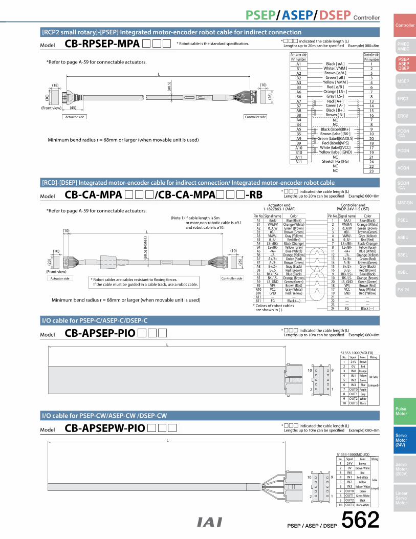
PSEP/ASEP/DSEP Controller
PSEP / ASEP / DSEP 562
PMECAMEC
Controller
Pulse Motor
Servo Motor (24V)
Servo Motor (200V)
LinearServo Motor
PSEP ASEPDSEP
MSEP
ERC3
ERC2
PCON-CA
PCON
ACON
SCON-CA
MSCON
PSEL
ASEL
SSEL
XSEL
PS-24
L
2
10 9
1 7
1098
654321
51353-1000 (MOLEX)
24V0VIN0IN1IN2IN3
OUT0OUT1OUT2OUT3
RedOrange Yellow
Brown
GreenBlue
PurpleGray
WhiteBlack
Signal Color Wiring No.
Flat Cable
(crimped)
Model CB-APSEP-PIO I/O cable for PSEP-C/ASEP-C/DSEP-C
* ccc indicated the cable length (L) Lengths up to 10m can be specified Example) 080=8m
2
10 9
1
L
7
1098
65432
Signal Color Wiring
Brown-White Red
Red-White
Brown
Cable
No.1
Yellow Yellow-White
GreenGreen-White
Black Black-White
(crimped)
51353-1000 (MOLEX)
24V0VIN0IN1IN2IN3
OUT0OUT1OUT2OUT3
Model CB-APSEPW-PIO I/O cable for PSEP-CW/ASEP-CW /DSEP-CW
* ccc indicated the cable length (L) Lengths up to 10m can be specified Example) 080=8m
L
(Front view)
(Note 1) If cable length is 5mor more,non-robotic cable is ø9.1 and robot cable is ø10.
* Colors of robot cables are shown in ( ).
Actuator end1-1827863-1 (AMP)
Controller endPADP-24V-1-S (JST)
Pin No. Signal name Color 1 Blue (Black) 2 VMM/V Orange (White) 5 _A/W Green (Brown) 3 Brown (Green) 4 VMM/- Gray (Yellow) 6 _B/- Red (Red) 7 LS+/BK+ Black (Orange) 8 LS-/BK- Yellow (Gray) 11 -/A+ Blue (White) 12 -/A- Orange (Yellow) 13 A+/B+ Green (Red) 14 A-/B- Brown (Green) 15 B+/Z+ Gray (Black) 16 B-/Z- Red (Brown) 9 BK+/LS+ Blue (Black) 10 BK-/LS- Orange (Brown) 20 LS_GND Green (Green) 18 VPS Brown (Red) 17 VCC Gray (White) 19 GND Red (Yellow) 21 — — 22 — — 23 — —
24 FG Black (—)
Pin No. Signal name Color A1 Blue(Black) B1 VMM/V Orange (White) A2 _A/W Green (Brown) B2 Brown (Green) A3 VMM/- Gray (Yellow) B3 _B/- Red (Red) A4 LS+/BK+ Black (Orange) B4 LS-/BK- Yellow (Gray) A6 -/A+ Blue (White) B6 -/A- Orange (Yellow) A7 A+/B+ Green (Red) B7 A-/B- Brown (Green) A8 B+/Z+ Gray (Black) B8 B-/Z- Red (Brown) A5 BK+/LS+ Blue (Black) B5 BK-/LS- Orange (Brown) A9 LS_GND Green (Green) B9 VPS Brown (Red) A10 VCC Gray (White) B10 GND Red (Yellow) A11 — — B11 FG Black (—)
* Robot cables are cables resistant to exing forces. If the cable must be guided in a cable track, use a robot cable.
Actuator side Controller side
(ø8.
5) (N
ote1
)
(10)
(10)
(10)
(23)
(26)
Model CB-CA-MPA /CB-CA-MPA -RB[RCD]-[DSEP] Integrated motor-encoder cable for indirect connection/ Integrated motor-encoder robot cable
* ccc indicated the cable length (L) Lengths up to 20m can be specified Example) 080=8m
Minimum bend radius r = 68mm or larger (when movable unit is used)
*Refer to page A-59 for connectable actuators.
Black [ øA ]Pin number
A1B1A2B2A3B3A6B6A7B7A8B8A4B4A5B5A9B9
A10B10A11B11
White [ VMM ]Brown [ ø/A ]Green [ øB ]
Yellow [ VMM ]Red [ ø/B ]
Orange [ LS+ ]Gray [ LS- ]Red [ A+ ]
Green [ A- ]Black [ B+ ]Brown [ B- ]
NCNC
Black (label)[BK+]Brown (label)[BK-]
Green (label)[GNDLS]Red (label)[VPS]
White (label)[VCC]Yellow (label)[GND]
NCShield [ FG ](FG)
NCNC
Pin number12534678
13141516789
102018171921242223
Controller sideActuator side
Actuator side Controller side
(Front view)
(ø8.
5)
L
(18) (10)
(45)
(30) (26)
* Robot cable is the standard specification. * ccc indicated the cable length (L) Lengths up to 20m can be specified Example) 080=8m Model CB-RPSEP-MPA
[RCP2 small rotary]-[PSEP] Integrated motor-encoder robot cable for indirect connection
Minimum bend radius r = 68mm or larger (when movable unit is used)
*Refer to page A-59 for connectable actuators.
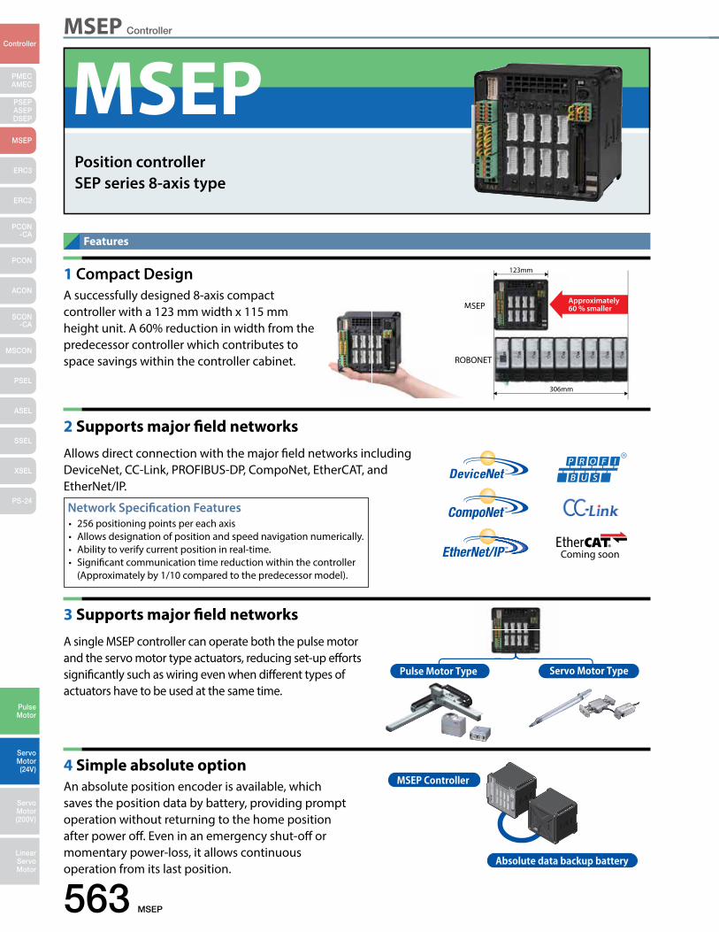
MSEP Controller
563 MSEP
PMECAMEC
Controller
Pulse Motor
Servo Motor (24V)
Servo Motor (200V)
LinearServo Motor
PSEP ASEPDSEP
MSEP
ERC3
ERC2
PCON-CA
PCON
ACON
SCON-CA
MSCON
PSEL
ASEL
SSEL
XSEL
PS-24
Pulse Motor Type Servo Motor Type
MSEP Controller
Absolute data backup battery
MSEP
123mm
306mm
ROBONETROB
Approximately 60 % smaller
1 Compact DesignA successfully designed 8-axis compact controller with a 123 mm width x 115 mm height unit. A 60% reduction in width from the predecessor controller which contributes to space savings within the controller cabinet.
2 Supports major field networks
Allows direct connection with the major field networks including DeviceNet, CC-Link, PROFIBUS-DP, CompoNet, EtherCAT, and EtherNet/IP.
3 Supports major field networks
A single MSEP controller can operate both the pulse motor and the servo motor type actuators, reducing set-up efforts significantly such as wiring even when different types of actuators have to be used at the same time.
4 Simple absolute optionAn absolute position encoder is available, which saves the position data by battery, providing prompt operation without returning to the home position after power off. Even in an emergency shut-off or momentary power-loss, it allows continuous operation from its last position.
Features
Network Specification Features• 256 positioning points per each axis • Allows designation of position and speed navigation numerically.• Ability to verify current position in real-time.• Significant communication time reduction within the controller (Approximately by 1/10 compared to the predecessor model).
MSEPPosition controllerSEP series 8-axis type
Coming soon
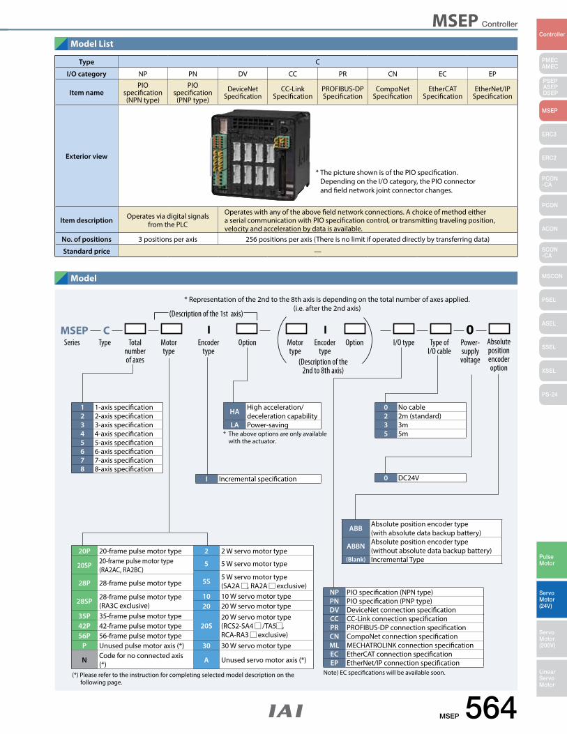
MSEP Controller
MSEP 564
PMECAMEC
Controller
Pulse Motor
Servo Motor (24V)
Servo Motor (200V)
LinearServo Motor
PSEP ASEPDSEP
MSEP
ERC3
ERC2
PCON-CA
PCON
ACON
SCON-CA
MSCON
PSEL
ASEL
SSEL
XSEL
PS-24
Model List
Model
Type C
I/O category NP PN DV CC PR CN EC EP
Item namePIO
specification(NPN type)
PIO specification
(PNP type)DeviceNet
SpecificationCC-Link
SpecificationPROFIBUS-DP Specification
CompoNetSpecification
EtherCAT Specification
EtherNet/IP Specification
Exterior view
Item description Operates via digital signals from the PLC
Operates with any of the above field network connections. A choice of method either a serial communication with PIO specification control, or transmitting traveling position, velocity and acceleration by data is available.
No. of positions 3 positions per axis 256 positions per axis (There is no limit if operated directly by transferring data)
Standard price —
* The picture shown is of the PIO specification. Depending on the I/O category, the PIO connector and field network joint connector changes.
1 1-axis specification2 2-axis specification3 3-axis specification4 4-axis specification5 5-axis specification6 6-axis specification7 7-axis specification8 8-axis specification
0 No cable2 2m (standard)3 3m5 5m
HA High acceleration/deceleration capability
LA Power-saving
* Representation of the 2nd to the 8th axis is depending on the total number of axes applied.(i.e. after the 2nd axis)
MSEP C 0 Absolute position encoder option
Totalnumberof axes
Motor type
Motor type
Series Type Encoder type
Encoder type
Option Option I/O type Type of I/O cable
Power-supply voltage
(Description of the 1st axis)
(Description of the 2nd to 8th axis)
(*) Please refer to the instruction for completing selected model description on the following page.
Note) EC specifications will be available soon.
* The above options are only available with the actuator.
I Incremental specification 0 DC24V
ABB Absolute position encoder type(with absolute data backup battery)
ABBN Absolute position encoder type (without absolute data backup battery)
(Blank) Incremental Type20P 20-frame pulse motor type 2 2 W servo motor type
20SP 20-frame pulse motor type(RA2AC, RA2BC)
5 5 W servo motor type
5S 5 W servo motor type(SA2A , RA2A exclusive)28P 28-frame pulse motor type
28SP 28-frame pulse motor type(RA3C exclusive)
10 10 W servo motor type20 20 W servo motor type
35P 35-frame pulse motor type20S
20 W servo motor type(RCS2-SA4 /TA5 , RCA-RA3 exclusive)
42P 42-frame pulse motor type56P 56-frame pulse motor type
P Unused pulse motor axis (*) 30 30 W servo motor type
N Code for no connected axis (*) A Unused servo motor axis (*)
NP PIO specification (NPN type)PN PIO specification (PNP type)DV DeviceNet connection specificationCC CC-Link connection specificationPR PROFIBUS-DP connection specificationCN CompoNet connection specificationML MECHATROLINK connection specificationEC EtherCAT connection specificationEP EtherNet/IP connection specification
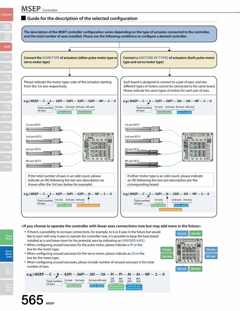
MSEP Controller
565 MSEP
PMECAMEC
Controller
Pulse Motor
Servo Motor (24V)
Servo Motor (200V)
LinearServo Motor
PSEP ASEPDSEP
MSEP
ERC3
ERC2
PCON-CA
PCON
ACON
SCON-CA
MSCON
PSEL
ASEL
SSEL
XSEL
PS-24
Connect the SAME TYPE of actuators (either pulse motor type or servo motor type)
The description of the MSEP controller configuration varies depending on the type of actuator connected to the controller, and the total number of axes installed. Please see the following conditions to configure a desired controller.
Connect a MIXTURE OF TYPES of actuators (both pulse motor type and servo motor type)
Guide for the description of the selected configuration
Each board is designed to connect to a pair of axes, and two different types of motors cannot be connected to the same board. Please indicate the same types of motors for each pair of axes.
Please indicate the motor type code of the actuator starting from the 1st axis respectively.
1st axis RCP2 1st axis RCP2
2nd axis RCP2 2nd axis RCP2
3rd axis RCP2 3rd axis RCA
4th axis RCP2 4th axis RCA
If the total number of axes is an odd count, please indicate an [N] following the last axis description (as shown after the 3rd axis below for example).
If either motor type is an odd count, please indicate an [N] following the last axis description per the corresponding board.
<If you choose to operate the controller with fewer axes connections now but may add more in the future>•If there’s a possibility to increase connections, for example, to 6 or 8 axes in the future but would
like to start with only 4 axes to operate the controller now, it is possible to keep the base board installed as is and leave room for the potential axes by indicating an [UNUSED AXIS].•When configuring unused axis/axes for the pulse motor, please indicate a [P] in the
box for the motor type.•When configuring unused axis/axes for the servo motor, please indicate an [A] in the
box for the motor type.•When configuring unused axis/axes, please include number of unused axis/axes in the total
number of axes.
1st axis
2nd axis
3rd axis 5th axis
7th axis
4th axis 6th axis
8th axis
e.g.) MSEP C 4 42PI 56PI 42PI 56PI NP 2 0
1st axis 2nd axis 3rd axis 4th axis
Pulse motor Pulse motor
Total number of axes
e.g.) MSEP C 3 42PI N 20SI 30I NP 2 0
1st axis 2nd axis 3rd axis
Pulse motor Servo motor
No connected axis
Total number of axes
e.g.) MSEP C 3 42PI 56PI 42PI N NP 2 0
1st axis 2nd axis 3rd axis
Pulse motor No connected axis
Total number of axes
e.g.) MSEP C 8 42PI 56PI 20I 10I PI PI AI AI NP 2 01st axis 2nd axis 3rd axis 7th
axis5th axis
8th axis
6th axis4th axis
Pulse motor Unused axis (Pulse motor)
Servo motor Unused axis (Servo motor)
Total number of axes
e.g.) MSEP C 4 42PI 56PI 20I 20I NP 2 0
1st axis 2nd axis 3rd axis 4th axis
Pulse motor Servo motor
Total number of axes
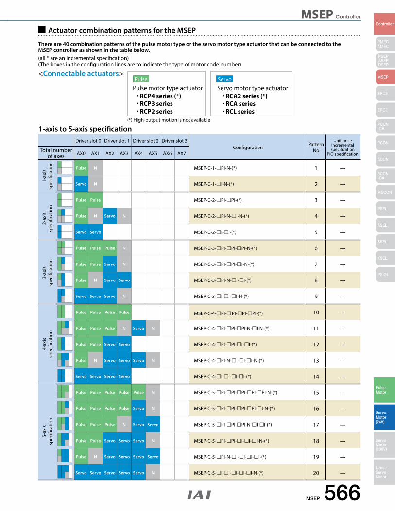
MSEP Controller
MSEP 566
PMECAMEC
Controller
Pulse Motor
Servo Motor (24V)
Servo Motor (200V)
LinearServo Motor
PSEP ASEPDSEP
MSEP
ERC3
ERC2
PCON-CA
PCON
ACON
SCON-CA
MSCON
PSEL
ASEL
SSEL
XSEL
PS-24
Actuator combination patterns for the MSEP
There are 40 combination patterns of the pulse motor type or the servo motor type actuator that can be connected to the MSEP controller as shown in the table below.(all * are an incremental specification) (The boxes in the configuration lines are to indicate the type of motor code number)
<Connectable actuators>Pulse
Pulse motor type actuator• RCP4 series (*)• RCP3 series• RCP2 series
Servo
Servo motor type actuator• RCA2 series (*)• RCA series• RCL series
(*) High-output motion is not available
1-axis to 5-axis specificationDriver slot 0 Driver slot 1 Driver slot 2 Driver slot 3
Configuration Pattern No
Unit priceIncremental specification
PIO specificationTotal number
of axes AX0 AX1 AX2 AX3 AX4 AX5 AX6 AX7
Pulse N MSEP-C-1-PI-N-(*) 1 —
Servo N MSEP-C-1-I-N-(*) 2 —
Pulse Pulse MSEP-C-2-PI-PI-(*) 3 —
Pulse N Servo N MSEP-C-2-PI-N-I-N-(*) 4 —
Servo Servo MSEP-C-2-I-I-(*) 5 —
Pulse Pulse Pulse N MSEP-C-3-PI-PI-PI-N-(*) 6 —
Pulse Pulse Servo N MSEP-C-3-PI-PI-I-N-(*) 7 —
Pulse N Servo Servo MSEP-C-3-PI-N-I-I-(*) 8 —
Servo Servo Servo N MSEP-C-3-I-I-I-N-(*) 9 —
Pulse Pulse Pulse Pulse MSEP-C-4-PI-PI-PI-PI-(*) 10 —
Pulse Pulse Pulse N Servo N MSEP-C-4-PI-PI-PI-N-I-N-(*) 11 —
Pulse Pulse Servo Servo MSEP-C-4-PI-PI-I-I-(*) 12 —
Pulse N Servo Servo Servo N MSEP-C-4-PI-N-I-I-I-N-(*) 13 —
Servo Servo Servo Servo MSEP-C-4-I-I-I-I-(*) 14 —
Pulse Pulse Pulse Pulse Pulse N MSEP-C-5-PI-PI-PI-PI-PI-N-(*) 15 —
Pulse Pulse Pulse Pulse Servo N MSEP-C-5-PI-PI-PI-PI-I-N-(*) 16 —
Pulse Pulse Pulse N Servo Servo MSEP-C-5-PI-PI-PI-N-I-I-(*) 17 —
Pulse Pulse Servo Servo Servo N MSEP-C-5-PI-PI-I-I-I-N-(*) 18 —
Pulse N Servo Servo Servo Servo MSEP-C-5-PI-N-I-I-I-I-(*) 19 —
Servo Servo Servo Servo Servo N MSEP-C-5-I-I-I-I-I-N-(*) 20 —
1-ax
is
spec
ifica
tion
2-ax
is
spec
ifica
tion
3-ax
is
spec
ifica
tion
4-ax
is
spec
ifica
tion
5-ax
is
spec
ifica
tion
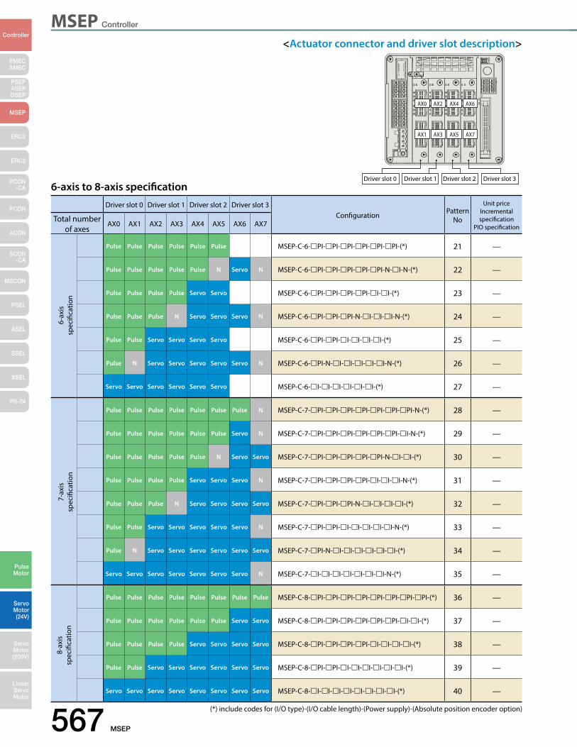
MSEP Controller
567 MSEP
PMECAMEC
Controller
Pulse Motor
Servo Motor (24V)
Servo Motor (200V)
LinearServo Motor
PSEP ASEPDSEP
MSEP
ERC3
ERC2
PCON-CA
PCON
ACON
SCON-CA
MSCON
PSEL
ASEL
SSEL
XSEL
PS-24
<Actuator connector and driver slot description>
6-axis to 8-axis specification
(*) include codes for (I/O type)-(I/O cable length)-(Power supply)-(Absolute position encoder option)
Driver slot 0 Driver slot 1 Driver slot 2 Driver slot 3Configuration Pattern
No
Unit priceIncremental specification
PIO specificationTotal number
of axesAX0 AX1 AX2 AX3 AX4 AX5 AX6 AX7
Pulse Pulse Pulse Pulse Pulse Pulse MSEP-C-6-PI-PI-PI-PI-PI-PI-(*) 21 —
Pulse Pulse Pulse Pulse Pulse N Servo N MSEP-C-6-PI-PI-PI-PI-PI-N-I-N-(*) 22 —
Pulse Pulse Pulse Pulse Servo Servo MSEP-C-6-PI-PI-PI-PI-I-I-(*) 23 —
Pulse Pulse Pulse N Servo Servo Servo N MSEP-C-6-PI-PI-PI-N-I-I-I-N-(*) 24 —
Pulse Pulse Servo Servo Servo Servo MSEP-C-6-PI-PI-I-I-I-I-(*) 25 —
Pulse N Servo Servo Servo Servo Servo N MSEP-C-6-PI-N-I-I-I-I-I-N-(*) 26 —
Servo Servo Servo Servo Servo Servo MSEP-C-6-I-I-I-I-I-I-(*) 27 —
Pulse Pulse Pulse Pulse Pulse Pulse Pulse N MSEP-C-7-PI-PI-PI-PI-PI-PI-PI-N-(*) 28 —
Pulse Pulse Pulse Pulse Pulse Pulse Servo N MSEP-C-7-PI-PI-PI-PI-PI-PI-I-N-(*) 29 —
Pulse Pulse Pulse Pulse Pulse N Servo Servo MSEP-C-7-PI-PI-PI-PI-PI-N-I-I-(*) 30 —
Pulse Pulse Pulse Pulse Servo Servo Servo N MSEP-C-7-PI-PI-PI-PI-I-I-I-N-(*) 31 —
Pulse Pulse Pulse N Servo Servo Servo Servo MSEP-C-7-PI-PI-PI-N-I-I-I-I-(*) 32 —
Pulse Pulse Servo Servo Servo Servo Servo N MSEP-C-7-PI-PI-I-I-I-I-I-N-(*) 33 —
Pulse N Servo Servo Servo Servo Servo Servo MSEP-C-7-PI-N-I-I-I-I-I-I-(*) 34 —
Servo Servo Servo Servo Servo Servo Servo N MSEP-C-7-I-I-I-I-I-I-I-N-(*) 35 —
Pulse Pulse Pulse Pulse Pulse Pulse Pulse Pulse MSEP-C-8-PI-PI-PI-PI-PI-PI-PI-PI-(*) 36 —
Pulse Pulse Pulse Pulse Pulse Pulse Servo Servo MSEP-C-8-PI-PI-PI-PI-PI-PI-I-I-(*) 37 —
Pulse Pulse Pulse Pulse Servo Servo Servo Servo MSEP-C-8-PI-PI-PI-PI-I-I-I-I-(*) 38 —
Pulse Pulse Servo Servo Servo Servo Servo Servo MSEP-C-8-PI-PI-I-I-I-I-I-I-(*) 39 —
Servo Servo Servo Servo Servo Servo Servo Servo MSEP-C-8-I-I-I-I-I-I-I-I-(*) 40 —
6-ax
is
spec
ifica
tion
7-ax
is
spec
ifica
tion
8-ax
is
spec
ifica
tion
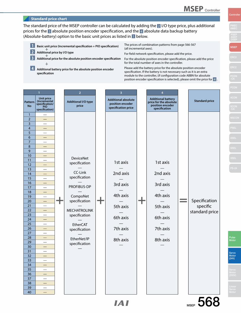
MSEP Controller
MSEP 568
PMECAMEC
Controller
Pulse Motor
Servo Motor (24V)
Servo Motor (200V)
LinearServo Motor
PSEP ASEPDSEP
MSEP
ERC3
ERC2
PCON-CA
PCON
ACON
SCON-CA
MSCON
PSEL
ASEL
SSEL
XSEL
PS-24
123
4
The standard price of the MSEP controller can be calculated by adding the 2 I/O type price, plus additional prices for the 3 absolute position encoder specification, and the 4 absolute data backup battery (Absolute-battery) option to the basic unit prices as listed in 1 below.
Basic unit price (Incremental specification + PIO specification)
Additional price by I/O type
Additional price for the absolute position encoder specification
Additional battery price for the absolute position encoder specification
The prices of combination patterns from page 566-567 (all incremental axes).
For field network specification, please add the price.
For the absolute position encoder specification, please add the price for the total number of axes in the controller.
Please add the battery price for the absolute position encoder specification. If the battery is not necessary such as it is an extra module to the controller, (if configuration code ABBN for absolute position encoder specification is selected), please omit the price for 4 .
Standard price chart
1
Pattern No
Unit price(Incremental specification/
PIO specification)
1 —2 —3 —4 —5 —6 —7 —8 —9 —
10 —11 —12 —13 —14 —15 —16 —17 —18 —19 —20 —21 —22 —23 —24 —25 —26 —27 —28 —29 —30 —31 —32 —33 —34 —35 —36 —37 —38 —39 —40 —
2
Additional I/O type price
DeviceNet specification
—CC-Link
specification—
PROFIBUS-DP—
CompoNet specification
—MECHATROLINK
specification—
EtherCAT specification
—EtherNet/IP
specification—
4
Additional battery price for the absolute
position encoder specification
1st axis—
2nd axis—
3rd axis—
4th axis—
5th axis—
6th axis—
7th axis—
8th axis—
3
Additional absolute position encoder
specification price
1st axis—
2nd axis—
3rd axis—
4th axis—
5th axis—
6th axis—
7th axis—
8th axis—
Standard price
Specification
specific standard price
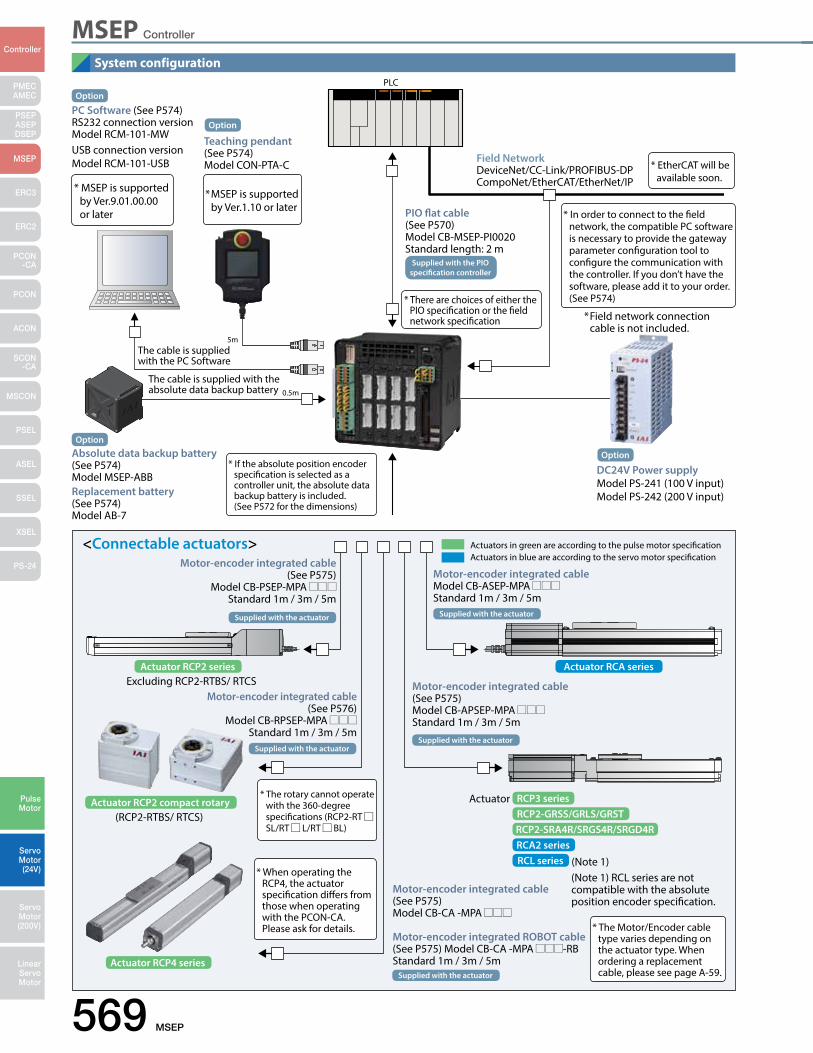
MSEP Controller
569 MSEP
PMECAMEC
Controller
Pulse Motor
Servo Motor (24V)
Servo Motor (200V)
LinearServo Motor
PSEP ASEPDSEP
MSEP
ERC3
ERC2
PCON-CA
PCON
ACON
SCON-CA
MSCON
PSEL
ASEL
SSEL
XSEL
PS-24
System configuration
* The rotary cannot operate with the 360-degree specifications (RCP2-RT SL/RT L/RT BL)
* When operating the RCP4, the actuator specification differs from those when operating with the PCON-CA.
Please ask for details. * The Motor/Encoder cable type varies depending on the actuator type. When ordering a replacement cable, please see page A-59.
<Connectable actuators> Actuators in green are according to the pulse motor specification Actuators in blue are according to the servo motor specificationMotor-encoder integrated cable
(See P575)Model CB-PSEP-MPA
Standard 1m / 3m / 5m
Excluding RCP2-RTBS/ RTCS
(RCP2-RTBS/ RTCS)
Supplied with the actuator Supplied with the actuator
Supplied with the actuatorSupplied with the actuator
Supplied with the actuator
PLC
5m
0.5m
PC Software (See P574)RS232 connection versionModel RCM-101-MW USB connection versionModel RCM-101-USB
* MSEP is supported by Ver.9.01.00.00 or later
* If the absolute position encoder specification is selected as a controller unit, the absolute data backup battery is included.
(See P572 for the dimensions)
* MSEP is supported by Ver.1.10 or later
* In order to connect to the field network, the compatible PC software is necessary to provide the gateway parameter configuration tool to configure the communication with the controller. If you don’t have the software, please add it to your order. (See P574)* There are choices of either the
PIO specification or the field network specification
* EtherCAT will be available soon.
The cable is supplied with the PC Software
The cable is supplied with the absolute data backup battery
Absolute data backup battery (See P574) Model MSEP-ABBReplacement battery(See P574) Model AB-7
Field NetworkDeviceNet/CC-Link/PROFIBUS-DPCompoNet/EtherCAT/EtherNet/IP
PIO flat cable(See P570)Model CB-MSEP-PI0020Standard length: 2 m
* Field network connection cable is not included.
Option
Teaching pendant (See P574)Model CON-PTA-C
Option
Option
Option
DC24V Power supplyModel PS-241 (100 V input)Model PS-242 (200 V input)
Supplied with the PIO specification controller
Actuator RCP2 series Actuator RCA series
RCA2 seriesRCL series
Actuator RCP2 compact rotary
Actuator RCP4 series
RCP3 seriesRCP2-GRSS/GRLS/GRSTRCP2-SRA4R/SRGS4R/SRGD4R
Motor-encoder integrated cable(See P576)
Model CB-RPSEP-MPA Standard 1m / 3m / 5m
Motor-encoder integrated cableModel CB-ASEP-MPA Standard 1m / 3m / 5m
Motor-encoder integrated cable(See P575)Model CB-APSEP-MPA Standard 1m / 3m / 5m
Actuator
(Note 1)(Note 1) RCL series are not compatible with the absolute position encoder specification.
Motor-encoder integrated cable(See P575)Model CB-CA -MPA
Motor-encoder integrated ROBOT cable (See P575) Model CB-CA -MPA -RB Standard 1m / 3m / 5m
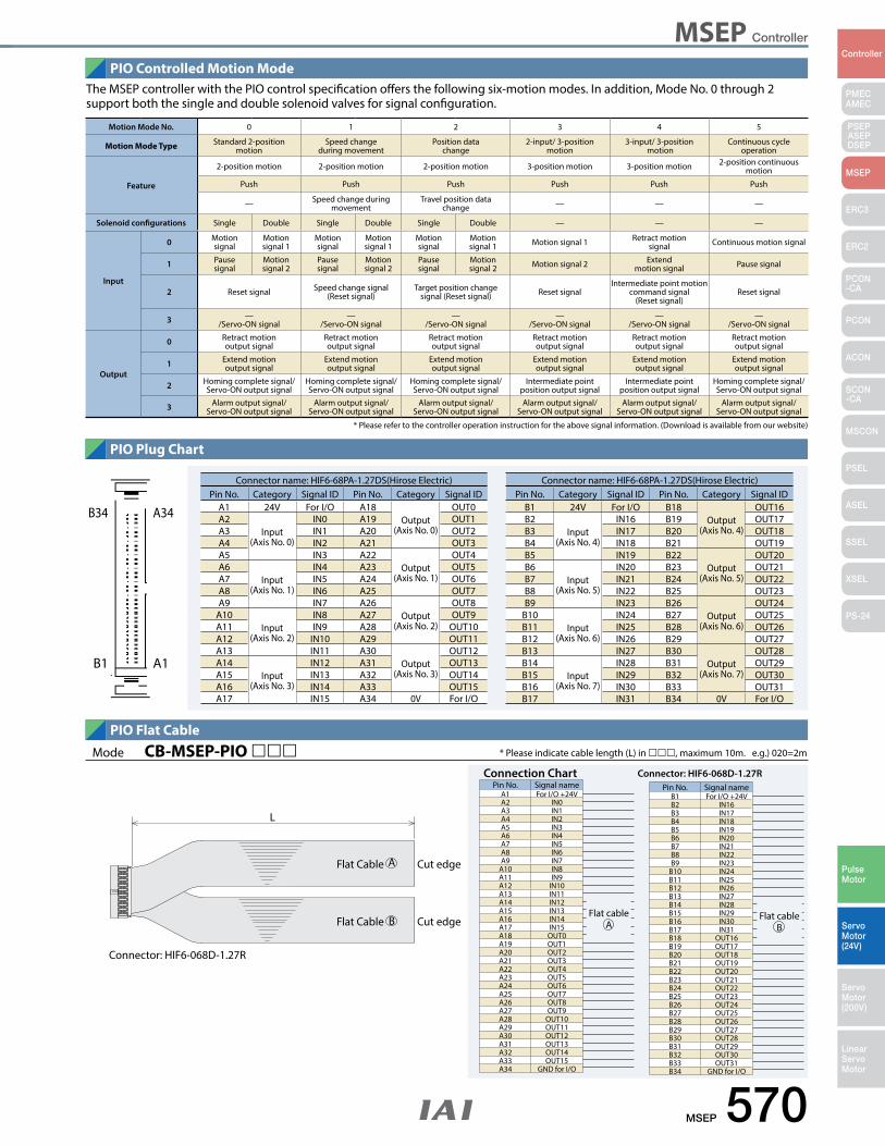
MSEP Controller
MSEP 570
PMECAMEC
Controller
Pulse Motor
Servo Motor (24V)
Servo Motor (200V)
LinearServo Motor
PSEP ASEPDSEP
MSEP
ERC3
ERC2
PCON-CA
PCON
ACON
SCON-CA
MSCON
PSEL
ASEL
SSEL
XSEL
PS-24
PIO Controlled Motion Mode
PIO Plug Chart
PIO Flat Cable
The MSEP controller with the PIO control specification offers the following six-motion modes. In addition, Mode No. 0 through 2 support both the single and double solenoid valves for signal configuration.
Motion Mode No. 0 1 2 3 4 5
Motion Mode Type Standard 2-position motion
Speed change during movement
Position data change
2-input/ 3-position motion
3-input/ 3-position motion
Continuous cycle operation
Feature
2-position motion 2-position motion 2-position motion 3-position motion 3-position motion 2-position continuous motion
Push Push Push Push Push Push
— Speed change during movement
Travel position data change — — —
Solenoid configurations Single Double Single Double Single Double — — —
Input
0 Motion signal
Motion signal 1
Motion signal
Motion signal 1
Motion signal
Motion signal 1 Motion signal 1 Retract motion
signal Continuous motion signal
1 Pause signal
Motion signal 2
Pause signal
Motion signal 2
Pause signal
Motion signal 2 Motion signal 2 Extend
motion signal Pause signal
2 Reset signal Speed change signal (Reset signal)
Target position change signal (Reset signal) Reset signal
Intermediate point motion command signal
(Reset signal)Reset signal
3 —/Servo-ON signal
—/Servo-ON signal
—/Servo-ON signal
—/Servo-ON signal
—/Servo-ON signal
—/Servo-ON signal
Output
0 Retract motion output signal
Retract motion output signal
Retract motion output signal
Retract motion output signal
Retract motion output signal
Retract motionoutput signal
1 Extend motion output signal
Extend motion output signal
Extend motion output signal
Extend motion output signal
Extend motion output signal
Extend motion output signal
2 Homing complete signal/ Servo-ON output signal
Homing complete signal/ Servo-ON output signal
Homing complete signal/ Servo-ON output signal
Intermediate point position output signal
Intermediate point position output signal
Homing complete signal/ Servo-ON output signal
3 Alarm output signal/ Servo-ON output signal
Alarm output signal/ Servo-ON output signal
Alarm output signal/ Servo-ON output signal
Alarm output signal/Servo-ON output signal
Alarm output signal/Servo-ON output signal
Alarm output signal/Servo-ON output signal
A34B34
A1B1
Connector name: HIF6-68PA-1.27DS(Hirose Electric)Pin No. Category Signal ID Pin No. Category Signal ID
A1 24V For I/O A18Output
(Axis No. 0)
OUT0A2
Input(Axis No. 0)
IN0 A19 OUT1A3 IN1 A20 OUT2A4 IN2 A21 OUT3A5 IN3 A22
Output(Axis No. 1)
OUT4A6
Input(Axis No. 1)
IN4 A23 OUT5A7 IN5 A24 OUT6A8 IN6 A25 OUT7A9 IN7 A26
Output(Axis No. 2)
OUT8A10
Input(Axis No. 2)
IN8 A27 OUT9A11 IN9 A28 OUT10A12 IN10 A29 OUT11A13 IN11 A30
Output(Axis No. 3)
OUT12A14
Input(Axis No. 3)
IN12 A31 OUT13A15 IN13 A32 OUT14A16 IN14 A33 OUT15A17 IN15 A34 0V For I/O
Connector name: HIF6-68PA-1.27DS(Hirose Electric)Pin No. Category Signal ID Pin No. Category Signal ID
B1 24V For I/O B18Output
(Axis No. 4)
OUT16B2
Input(Axis No. 4)
IN16 B19 OUT17B3 IN17 B20 OUT18B4 IN18 B21 OUT19B5 IN19 B22
Output(Axis No. 5)
OUT20B6
Input(Axis No. 5)
IN20 B23 OUT21B7 IN21 B24 OUT22B8 IN22 B25 OUT23B9 IN23 B26
Output(Axis No. 6)
OUT24B10
Input(Axis No. 6)
IN24 B27 OUT25B11 IN25 B28 OUT26B12 IN26 B29 OUT27B13 IN27 B30
Output(Axis No. 7)
OUT28B14
Input(Axis No. 7)
IN28 B31 OUT29B15 IN29 B32 OUT30B16 IN30 B33 OUT31B17 IN31 B34 0V For I/O
* Please refer to the controller operation instruction for the above signal information. (Download is available from our website)
Connector: HIF6-068D-1.27R
Flat Cable
Flat Cable
Cut edge
Cut edgeFlat cable
A
Connection ChartPin No. Signal name
A1 For I/O +24VA2 IN0A3 IN1A4 IN2A5 IN3A6 IN4A7 IN5A8 IN6A9 IN7
A10 IN8A11 IN9A12 IN10A13 IN11A14 IN12A15 IN13A16 IN14A17 IN15A18 OUT0A19 OUT1A20 OUT2A21 OUT3A22 OUT4A23 OUT5A24 OUT6A25 OUT7A26 OUT8A27 OUT9A28 OUT10A29 OUT11A30 OUT12A31 OUT13A32 OUT14A33 OUT15A34 GND for I/O
Flat cableB
Connector: HIF6-068D-1.27RPin No. Signal name
B1 For I/O +24VB2 IN16B3 IN17B4 IN18B5 IN19B6 IN20B7 IN21B8 IN22B9 IN23
B10 IN24B11 IN25B12 IN26B13 IN27B14 IN28B15 IN29B16 IN30B17 IN31B18 OUT16B19 OUT17B20 OUT18B21 OUT19B22 OUT20B23 OUT21B24 OUT22B25 OUT23B26 OUT24B27 OUT25B28 OUT26B29 OUT27B30 OUT28B31 OUT29B32 OUT30B33 OUT31B34 GND for I/O
* Please indicate cable length (L) in , maximum 10m. e.g.) 020=2mMode CB-MSEP-PIO
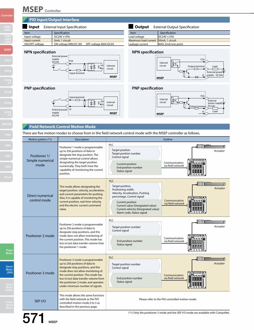
MSEP Controller
571 MSEP
PMECAMEC
Controller
Pulse Motor
Servo Motor (24V)
Servo Motor (200V)
LinearServo Motor
PSEP ASEPDSEP
MSEP
ERC3
ERC2
PCON-CA
PCON
ACON
SCON-CA
MSCON
PSEL
ASEL
SSEL
XSEL
PS-24
PIO Input/Output Interface
Field Network Control Motion Mode
Input External Input Specification Output External Output SpecificationItem SpecificationInput voltage DC24V ±10%Input current 5mA, 1 circuitON/OFF voltage ON voltage MIN.DC18V OFF voltage MAX.DC6V
Item SpecificationLoad voltage DC24V ±10%Maximum load current 50mA, 1 circuitLeakage current MAX 2mA/one point
NPN specificationExternal power supplyDC24V P24
Input terminalMSEP
Internal circuit
PNP specification
External power supplyDC24V
Input terminal
MSEP
Internal circuit
N
PNP specification
P24
Output terminal
External power supply DC24V
LoadMSEP
Internal circuit
N
NPN specification
P24
Output terminal
External power supply DC24V
Load
MSEP
Internal circuit
N
There are five motion modes to choose from in the field network control mode with the MSEP controller as follows.
Motion pattern (*1) Description Outline
Positioner 1/Simple numerical
mode
Positioner 1 mode is programmable up to 256 positions of data to designate the stop position. The simple numerical control allows designating the target position numerically. They both have the capability of monitoring the current position.
Direct numerical control mode
This mode allows designating the target position, velocity, acceleration, and current parameters for pushing. Also, it is capable of monitoring the current position, real-time velocity, and the electric current command value.
Positioner 2 mode
Positioner 2 mode is programmable up to 256 positions of data to designate stop positions, and this mode does not allow monitoring of the current position. This mode has less in/out data transfer volume than the positioner 1 mode.
Positioner 3 mode
Positioner 3 mode is programmable up to 256 positions of data to designate stop positions, and this mode does not allow monitoring of the current position. This mode has less in/out data transfer volume from the positioner 2 mode, and operates under minimum number of signals.
SEP I/O
This mode allows the same functions with the field network as the PIO controlled motion mode 0 to 5 as described in the previous page.
Please refer to the PIO controlled motion mode.
Communication via field network
Actuator
PLC
Target positionTarget position numberControl signal
Current positionEnd position numberStatus signal
Communication via field network
Actuator
PLC
Target position numberControl signal
End position numberStatus signal
Communication via field network
Actuator
PLC
Target position numberControl signal
End position numberStatus signal
Communication via field network
Actuator
PLC
Target position, Positioning width, Velocity, Acceleration, Pushing percentage, Control signal
Current positionCurrent value (Designated value)Current velocity (Designated value)Alarm code, Status signal
(*1) Only the positioner 3 mode and the SEP I/O mode are available with CompoNet.
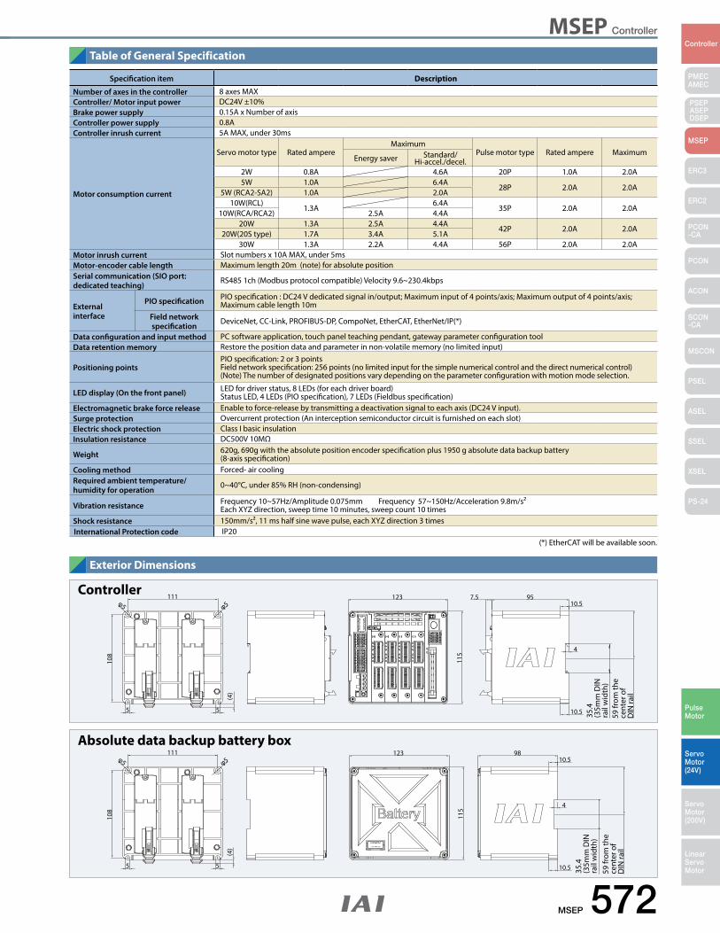
MSEP Controller
MSEP 572
PMECAMEC
Controller
Pulse Motor
Servo Motor (24V)
Servo Motor (200V)
LinearServo Motor
PSEP ASEPDSEP
MSEP
ERC3
ERC2
PCON-CA
PCON
ACON
SCON-CA
MSCON
PSEL
ASEL
SSEL
XSEL
PS-24
Table of General Specification
Exterior Dimensions
Controller123
115
95111
108
7.510.5φ5φ5
5 5
(4)
4
10.5 35.4
(35m
m D
IN
rail
wid
th)
59 fr
om th
e ce
nter
of
DIN
rail
Absolute data backup battery box123
115
98111
108
10.5φ5φ5
5 5
(4)
4
10.5 35.4
(35m
m D
IN
rail
wid
th)
59 fr
om th
e ce
nter
of
DIN
rail
Specification item Description
Number of axes in the controller 8 axes MAXController/ Motor input power DC24V ±10%Brake power supply 0.15A x Number of axisController power supply 0.8AController inrush current 5A MAX, under 30ms
Motor consumption current
Servo motor type Rated ampereMaximum
Pulse motor type Rated ampere MaximumEnergy saver Standard/
Hi-accel./decel.2W 0.8A 4.6A 20P 1.0A 2.0A5W 1.0A 6.4A
28P 2.0A 2.0A5W (RCA2-SA2) 1.0A 2.0A
10W(RCL)1.3A
6.4A35P 2.0A 2.0A
10W(RCA/RCA2) 2.5A 4.4A20W 1.3A 2.5A 4.4A
42P 2.0A 2.0A20W(20S type) 1.7A 3.4A 5.1A
30W 1.3A 2.2A 4.4A 56P 2.0A 2.0AMotor inrush current Slot numbers x 10A MAX, under 5msMotor-encoder cable length Maximum length 20m (note) for absolute positionSerial communication (SIO port: dedicated teaching)
RS485 1ch (Modbus protocol compatible) Velocity 9.6~230.4kbps
External interface
PIO specification PIO specification : DC24 V dedicated signal in/output; Maximum input of 4 points/axis; Maximum output of 4 points/axis; Maximum cable length 10m
Field network specification
DeviceNet, CC-Link, PROFIBUS-DP, CompoNet, EtherCAT, EtherNet/IP(*)
Data configuration and input method PC software application, touch panel teaching pendant, gateway parameter configuration toolData retention memory Restore the position data and parameter in non-volatile memory (no limited input)
Positioning pointsPIO specification: 2 or 3 pointsField network specification: 256 points (no limited input for the simple numerical control and the direct numerical control)(Note) The number of designated positions vary depending on the parameter configuration with motion mode selection.
LED display (On the front panel) LED for driver status, 8 LEDs (for each driver board)Status LED, 4 LEDs (PIO specification), 7 LEDs (Fieldbus specification)
Electromagnetic brake force release Enable to force-release by transmitting a deactivation signal to each axis (DC24 V input).Surge protection Overcurrent protection (An interception semiconductor circuit is furnished on each slot)Electric shock protection Class I basic insulationInsulation resistance DC500V 10MΩ
Weight 620g, 690g with the absolute position encoder specification plus 1950 g absolute data backup battery(8-axis specification)
Cooling method Forced- air coolingRequired ambient temperature/ humidity for operation
0~40°C, under 85% RH (non-condensing)
Vibration resistance Frequency 10~57Hz/Amplitude 0.075mm Frequency 57~150Hz/Acceleration 9.8m/s²Each XYZ direction, sweep time 10 minutes, sweep count 10 times
Shock resistance 150mm/s², 11 ms half sine wave pulse, each XYZ direction 3 timesInternational Protection code IP20
(*) EtherCAT will be available soon.

MSEP Controller
573 MSEP
PMECAMEC
Controller
Pulse Motor
Servo Motor (24V)
Servo Motor (200V)
LinearServo Motor
PSEP ASEPDSEP
MSEP
ERC3
ERC2
PCON-CA
PCON
ACON
SCON-CA
MSCON
PSEL
ASEL
SSEL
XSEL
PS-24
Names of the MSEP Controller components
AX1 AX3 AX5 AX7
AX0 AX2 AX4 AX6 7 Fan unit
8 AUTO/MANUAL switch
9 SIO connector
10 System I/O connector
Motor-encoder connectors for the actuator connection1
Connector for the absolute data backup battery (Note 1)2
Connector for the external brake input3
Connector for the emergency stop input for power source shut-off
4
Information card for the connecting axes configuration
5
+24 V power source input connector6
PIO connector/ field network connection connector11
Note) All the connectors are represented as AX0 through AX7. Please be aware that the motor-encoder cable for the first axis is to be connected to AX0 and the second axis to AX1 respectively.
Descriptions of the components
1
5
9
2
6
10
3
7
11
4
8
Motor-encoder connectors for the actuator connectionConnect motor-encoder cable to the actuator.
Connector for the absolute data backup battery (Note 1) Connector is not used for the incremental specification.Connect the absolute data backup battery if the controller has the absolute position encoder specification.
Connector for the external brake inputThe connector to input a signal to release the brake for the actuator externally.
Connector for the emergency stop input for power source shut-offThe emergency stop input connector to connect in/output terminal of the external relay of the motor drive shut –off and each driver slot (*1).
Information card for configuration of the connecting axes The information card contains information regarding the configuration of the controller axes which is removable to examine the contents.
+24 V power source input connectorThe main power source connector for the controller: Motor drive source shut-down is possible while restoring the power source for the controller unit in case of an emergency shut-down; This is because the terminals for the power source of the motor and the controller are separate.
Fan unitEasily replaceable fan unit. (Replacement fan unit: Model MSEP-FU).
AUTO/MANUAL switchTo switch automatic operation to/from manual operation.
SIO connectorTo connect teaching box and the connecting cable for PC software.
System I/O connectorThe connector for remote AUTO/MANU switch input and emergency stop input for the entire controller with functions including an external regeneration-resistance expansion terminal.
PIO connector/ field network connection connectorThe PIO specification — connects to a 68-pin ribbon I/O cable.The field network specification — connects to a field network type specified on the MSEP controller.
(*1) The shut-off feature is available on a single slot basis which is for two axes per slot. Please note that a single axis basis cannot be accommodated.
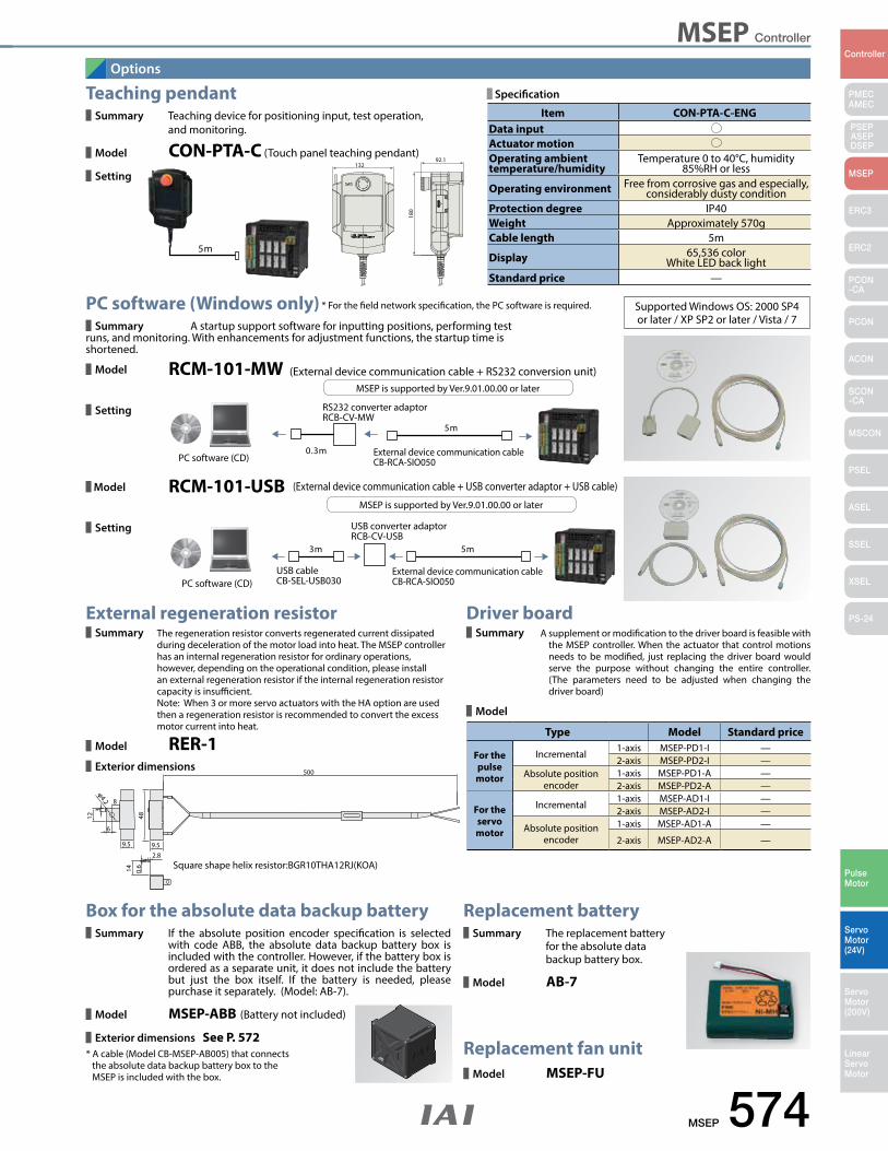
MSEP Controller
MSEP 574
PMECAMEC
Controller
Pulse Motor
Servo Motor (24V)
Servo Motor (200V)
LinearServo Motor
PSEP ASEPDSEP
MSEP
ERC3
ERC2
PCON-CA
PCON
ACON
SCON-CA
MSCON
PSEL
ASEL
SSEL
XSEL
PS-24
Options
Teaching pendant Summary Teaching device for positioning input, test operation,
and monitoring.
Model CON-PTA-C (Touch panel teaching pendant)
Setting
PC software (Windows only) Summary A startup support software for inputting positions, performing test
runs, and monitoring. With enhancements for adjustment functions, the startup time is shortened.
Model RCM-101-MW
Setting
* For the field network specification, the PC software is required.
(External device communication cable + RS232 conversion unit)MSEP is supported by Ver.9.01.00.00 or later
0.3m
5m
RS232 converter adaptorRCB-CV-MW
PC software (CD) External device communication cableCB-RCA-SIO050
13292.1
180
5m
Model RCM-101-USB
Setting
(External device communication cable + USB converter adaptor + USB cable)
MSEP is supported by Ver.9.01.00.00 or later
5m3m
PC software (CD)External device communication cableCB-RCA-SIO050
USB converter adaptorRCB-CV-USB
USB cableCB-SEL-USB030
Driver board Summary A supplement or modification to the driver board is feasible with
the MSEP controller. When the actuator that control motions needs to be modified, just replacing the driver board would serve the purpose without changing the entire controller. (The parameters need to be adjusted when changing the driver board)
Model
Square shape helix resistor:BGR10THA12RJ(KOA)
500
φ4.2
12
14
9.59.5
48
6
8
3
2.8
0.6
Type Model Standard price
For the pulse motor
Incremental1-axis MSEP-PD1-I —2-axis MSEP-PD2-I —
Absolute position encoder
1-axis MSEP-PD1-A —2-axis MSEP-PD2-A —
For the servo motor
Incremental1-axis MSEP-AD1-I —2-axis MSEP-AD2-I —
Absolute position encoder
1-axis MSEP-AD1-A —
2-axis MSEP-AD2-A —
External regeneration resistor Summary The regeneration resistor converts regenerated current dissipated
during deceleration of the motor load into heat. The MSEP controller has an internal regeneration resistor for ordinary operations, however, depending on the operational condition, please install an external regeneration resistor if the internal regeneration resistor capacity is insufficient. Note: When 3 or more servo actuators with the HA option are used then a regeneration resistor is recommended to convert the excess motor current into heat.
Model RER-1 Exterior dimensions
Box for the absolute data backup battery Summary If the absolute position encoder specification is selected
with code ABB, the absolute data backup battery box is included with the controller. However, if the battery box is ordered as a separate unit, it does not include the battery but just the box itself. If the battery is needed, please purchase it separately. (Model: AB-7).
Model MSEP-ABB (Battery not included)
Exterior dimensions See P. 572
Replacement battery Summary The replacement battery
for the absolute data backup battery box.
Model AB-7
Replacement fan unit Model MSEP-FU
* A cable (Model CB-MSEP-AB005) that connects the absolute data backup battery box to the MSEP is included with the box.
Item CON-PTA-C-ENGData inputActuator motionOperating ambient temperature/humidity
Temperature 0 to 40°C, humidity 85%RH or less
Operating environment Free from corrosive gas and especially, considerably dusty condition
Protection degree IP40Weight Approximately 570gCable length 5m
Display 65,536 colorWhite LED back light
Standard price —
Specification
Supported Windows OS: 2000 SP4 or later / XP SP2 or later / Vista / 7
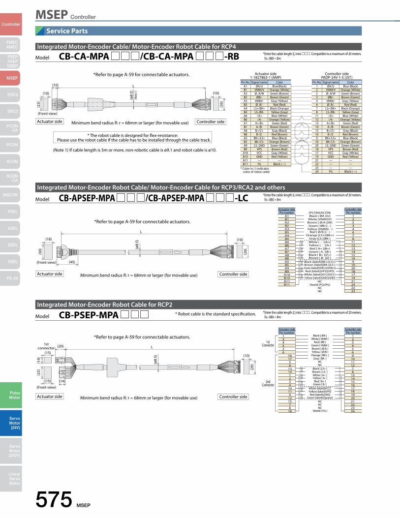
575 MSEP
PMECAMEC
Controller
Pulse Motor
Servo Motor (24V)
Servo Motor (200V)
LinearServo Motor
PSEP ASEPDSEP
MSEP
ERC3
ERC2
PCON-CA
PCON
ACON
SCON-CA
MSCON
PSEL
ASEL
SSEL
XSEL
PS-24
Service Parts
MSEP Controller
L
(10)
(10)
(23)
(10)
(26)
(Not
e 1)
(ø8.
5)
(Front view)
Integrated Motor-Encoder Cable/ Motor-Encoder Robot Cable for RCP4
* The robot cable is designed for flex-resistance: Please use the robot cable if the cable has to be installed through the cable track.
Pin No. Signal name ColorA1 ØA/U Blue(Black)B1 VMM/V Orange (White)A2 Ø_A/W Green (Brown)B2 ØB/- Brown (Green)A3 VMM/- Gray (Yellow)B3 Ø_B/- Red (Red)A4 LS+/BK+ Black (Orange)B4 LS-/BK- Yellow (Gray)A6 -/A+ Blue (White)B6 -/A- Orange (Yellow)A7 A+/B+ Green (Red)B7 A-/B- Brown (Green)A8 B+/Z+ Gray (Black)B8 B-/Z- Red (Brown)A5 BK+/LS+ Blue (Black)B5 BK-/LS- Orange (Brown)A9 LS_GND Green (Green)B9 VPS Brown (Red)
A10 VCC Gray (White)B10 GND Red (Yellow)A11 — —B11 FG Black (—)
Pin No. Signal name Color1 ØA/U Blue (Black)2 VMM/V Orange (White)5 Ø_A/W Green (Brown)3 ØB/- Brown (Green)4 VMM/- Gray (Yellow)6 Ø_B/- Red (Red)7 LS+/BK+ Black (Orange)8 LS-/BK- Yellow (Gray)
11 -/A+ Blue (White)12 -/A- Orange (Yellow)13 A+/B+ Green (Red)14 A-/B- Brown (Green)15 B+/Z+ Gray (Black)16 B-/Z- Red (Brown)9 BK+/LS+ Blue (Black)
10 BK-/LS- Orange (Brown)20 LS_GND Green (Green)18 VPS Brown (Red)17 VCC Gray (White)19 GND Red (Yellow)21 — —22 — —23 — —24 FG Black (—)
* Color in ( ) indicates color of robot cable
Actuator side1-1827863-1 (AMP)
Controller sidePADP-24V-1-S (JST)
Integrated Motor-Encoder Robot Cable for RCP2
Integrated Motor-Encoder Robot Cable/ Motor-Encoder Cable for RCP3/RCA2 and others
* Robot cable is the standard specification.
Model CB-CA-MPA /CB-CA-MPA -RB
Model CB-PSEP-MPA
Model CB-APSEP-MPA /CB-APSEP-MPA -LC
*Enter the cable length (L) into . Compatible to a maximum of 20 meters. Ex.: 080 = 8m
*Enter the cable length (L) into . Compatible to a maximum of 20 meters. Ex.: 080 = 8m
* Enter the cable length (L) into . Compatible to a maximum of 20 meters. Ex.: 080 = 8m
*Refer to page A-59 for connectable actuators.
Minimum bend radius R: r = 68mm or larger (for movable use)Actuator side Controller side
(Note 1) If cable length is 5m or more, non-robotic cable is ø9.1 and robot cable is ø10.
L
(10)(2
6)(18)
(30)
(45)
(ø8.
5)
(Front view)
*Refer to page A-59 for connectable actuators.
Minimum bend radius R: r = 68mm or larger (for movable use)Actuator side Controller side
Controller sideActuator side
NC
Black (label)[BK+](LS+)
White [ - ](A+)
[PCON](ACON)Pin numberA1B1A2B2A3B3A4B4A6B6A7B7A8B8A5B5A9B9
A10B10A11B11
Pin number12534678
1112131415169
102018171921242223
Black [ ØA ](U)White [VMM](V)
Brown [ Ø/A ](W)Green [ ØB ]( - )
Yellow [VMM]( - )Red [ Ø/B ]( - )
Orange [LS+](BK+)Gray [LS-](BK-)
Yellow [ - ](A-)Red [ A+ ](B+)Green [ A- ](B-)Black [ B+ ](Z+)Brown [ B- ](Z-)
Brown (label)[BK-](LS-)Green (label)[GNDLS](GNDLS)Red (label)[VPS](VPS)
White (label)[VCC](VCC)Yellow (label)[GND](GND)
Shield [FG](FG)NCNC
1st connector L
(10)
(26)
(15)
(25)
(15)
(14)
(20)
(14)
(ø8.
5)
(Front view)
*Refer to page A-59 for connectable actuators.
Minimum bend radius R: r = 68mm or larger (for movable use)Actuator side Controller side
Controller sideActuator side
Black [ ØA ]Pin number
124536
161756
13141234
10119
121578
18
White [ VMM ]Red [ ØB ]
Green [ VMM ]Brown [ Ø/A ]Yellow [ Ø/B ]Orange [ BK+ ]
Gray [ BK- ]NCNC
Black [ LS+ ]Brown [ LS- ]White [ A+ ]Yellow [ A- ]
Red [ B+ ]Green [ B- ]
White (label)[VCC]Yellow (label)[VPS]Red (label)[GND]
Green (label)[(Spare)]NCNCNC
Shield [ FG ]
Pin number1234569
10111278
131415161718192021222324
1stConnector
2ndConnector
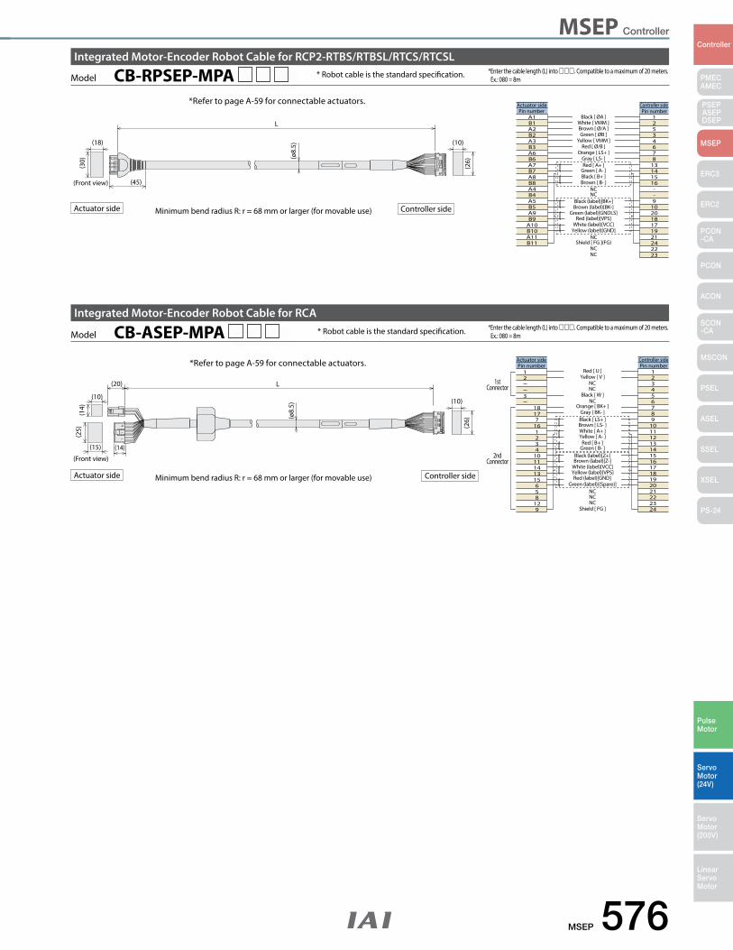
MSEP 576
PMECAMEC
Controller
Pulse Motor
Servo Motor (24V)
Servo Motor (200V)
LinearServo Motor
PSEP ASEPDSEP
MSEP
ERC3
ERC2
PCON-CA
PCON
ACON
SCON-CA
MSCON
PSEL
ASEL
SSEL
XSEL
PS-24
MSEP Controller
* Robot cable is the standard specification.
* Robot cable is the standard specification.Model CB-ASEP-MPA
Model CB-RPSEP-MPA *Enter the cable length (L) into . Compatible to a maximum of 20 meters. Ex.: 080 = 8m
*Enter the cable length (L) into . Compatible to a maximum of 20 meters. Ex.: 080 = 8m
*Refer to page A-59 for connectable actuators.
*Refer to page A-59 for connectable actuators.
Integrated Motor-Encoder Robot Cable for RCP2-RTBS/RTBSL/RTCS/RTCSL
Integrated Motor-Encoder Robot Cable for RCA
Minimum bend radius R: r = 68 mm or larger (for movable use)Actuator side Controller side
Minimum bend radius R: r = 68 mm or larger (for movable use)Actuator side Controller side
L
(10)
(26)
(15)
(25)
(10)
(14)
(20)
(14)
(ø8.
5)
(Front view)
L
(10)
(26)
(45)
(18)
(30) (ø
8.5)
(Front view)
Black [ ØA ]Pin number
A1B1A2B2A3B3A6B6A7B7A8B8A4B4A5B5A9B9
A10B10A11B11
White [ VMM ]Brown [ Ø/A ]Green [ ØB ]
Yellow [ VMM ]Red [ Ø/B ]
Orange [ LS+ ]Gray [ LS- ]Red [ A+ ]
Green [ A- ]Black [ B+ ]Brown [ B- ]
NCNC
Black (label)[BK+]Brown (label)[BK-]
Green (label)[GNDLS]Red (label)[VPS]
White (label)[VCC]Yellow (label)[GND]
NCShield [ FG ](FG)
NCNC
Pin number12534678
13141516--9
102018171921242223
Controller sideActuator side
Red [ U ]12
3
18177
161234
1011141315658
129
Yellow [ V ]NCNC
Black [ W ]NC
Orange [ BK+ ]Gray [ BK- ]Black [ LS+ ]Brown [ LS- ]White [ A+ ]Yellow [ A- ]
Red [ B+ ]Green [ B- ]
Black (label)[Z+]Brown (label)[Z-]
White (label)[VCC]Yellow (label)[VPS]Red (label)[GND]
Green (label)[(Spare)]NCNCNC
Shield [ FG ]
123456789
101112131415161718192021222324
Controller side Actuator sidePin number Pin number
1stConnector
2ndConnector
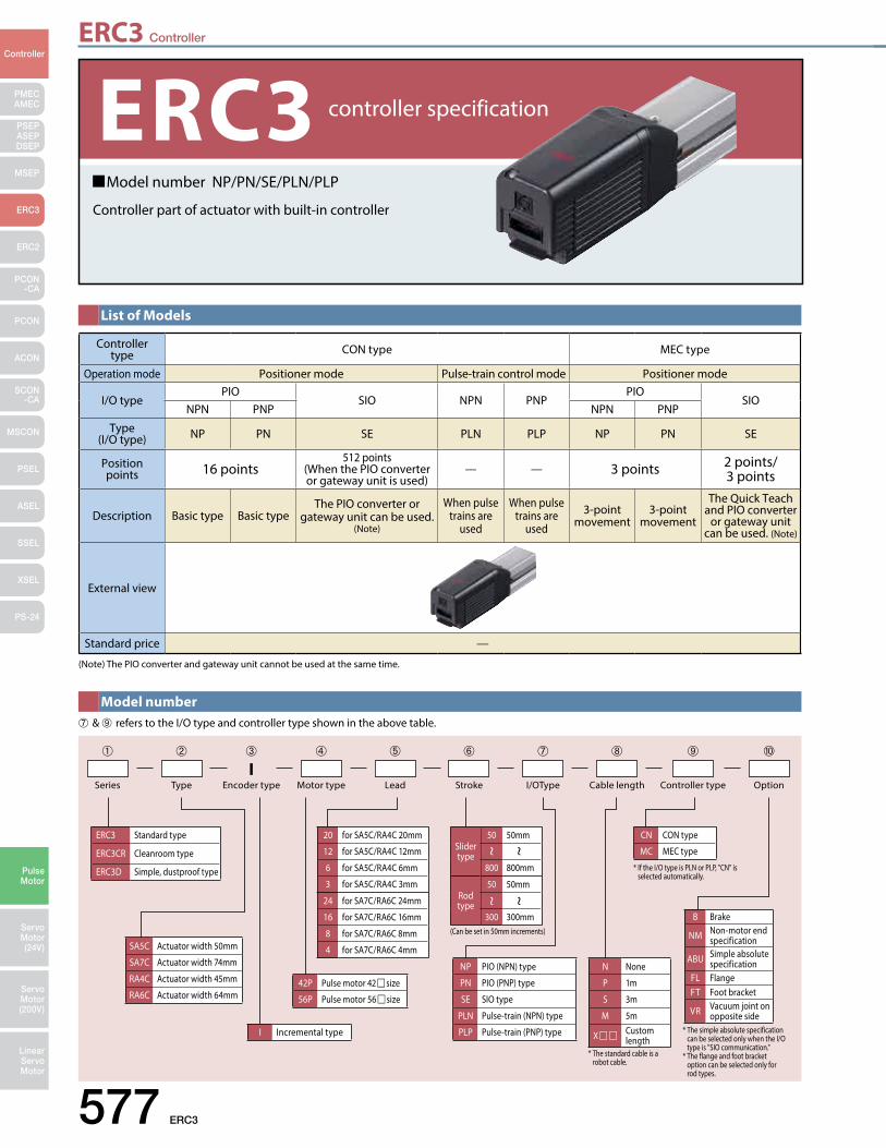
ERC3 Controller
577 ERC3
PMECAMEC
Controller
Pulse Motor
Servo Motor (24V)
Servo Motor (200V)
LinearServo Motor
PSEP ASEPDSEP
MSEP
ERC3
ERC2
PCON-CA
PCON
ACON
SCON-CA
MSCON
PSEL
ASEL
SSEL
XSEL
PS-24
Model number NP/PN/SE/PLN/PLP
Controller part of actuator with built-in controller
ERC3 controller specification
List of Models
Controller type CON type MEC type
Operation mode Positioner mode Pulse-train control mode Positioner mode
I/O typePIO
SIO NPN PNPPIO
SIONPN PNP NPN PNP
Type(I/O type) NP PN SE PLN PLP NP PN SE
Position points 16 points
512 points (When the PIO converter or gateway unit is used)
— — 3 points 2 points/3 points
Description Basic type Basic typeThe PIO converter or
gateway unit can be used. (Note)
When pulse trains are
used
When pulse trains are
used
3-point movement
3-point movement
The Quick Teach and PIO converter
or gateway unit can be used. (Note)
External view
Standard price —
(Note) The PIO converter and gateway unit cannot be used at the same time.
Model number➆ & ➈ refers to the I/O type and controller type shown in the above table.
20 for SA5C/RA4C 20mm
12 for SA5C/RA4C 12mm
6 for SA5C/RA4C 6mm
3 for SA5C/RA4C 3mm
24 for SA7C/RA6C 24mm
16 for SA7C/RA6C 16mm
8 for SA7C/RA6C 8mm
4 for SA7C/RA6C 4mm
Series Type Motor type Stroke Controller type OptionLead I/OType Cable lengthI
Encoder type
N None
P 1m
S 3m
M 5m
X Customlength
NP PIO (NPN) type
PN PIO (PNP) type
SE SIO type
PLN Pulse-train (NPN) type
PLP Pulse-train (PNP) type
CN CON type
MC MEC type
(Can be set in 50mm increments)
* If the I/O type is PLN or PLP, "CN" is selected automatically.
* The simple absolute specification can be selected only when the I/O type is "SIO communication." * The flange and foot bracket option can be selected only for rod types.
* The standard cable is a robot cable.
ERC3 Standard type
ERC3CR Cleanroom type
ERC3D Simple, dustproof type
42P Pulse motor 42size
56P Pulse motor 56size
I Incremental type
➀ ➁ ➃ ➅ ➈ ➉➄ ➆ ➇➂
Slider type
50 50mm
800 800mm
Rod type
50 50mm
300 300mm B Brake
NM Non-motor end specification
ABU Simple absolute specification
FL Flange FT Foot bracket
VR Vacuum joint on opposite side
SA5C Actuator width 50mm
SA7C Actuator width 74mm
RA4C Actuator width 45mm
RA6C Actuator width 64mm
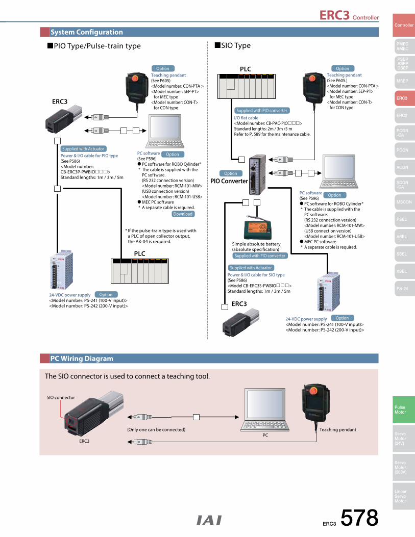
ERC3 Controller
ERC3 578
PMECAMEC
Controller
Pulse Motor
Servo Motor (24V)
Servo Motor (200V)
LinearServo Motor
PSEP ASEPDSEP
MSEP
ERC3
ERC2
PCON-CA
PCON
ACON
SCON-CA
MSCON
PSEL
ASEL
SSEL
XSEL
PS-24
System Configuration
PC Wiring Diagram
SIO connector
(Only one can be connected) Teaching pendantPC
ERC3
The SIO connector is used to connect a teaching tool.
PIO Type/Pulse-train type
ERC3
PLC
ERC3
PIO Converter
PLC
SIO Type
I/O flat cable<Model number: CB-PAC-PIO>Standard lengths: 2m / 3m /5 mRefer to P. 589 for the maintenance cable.
Power & I/O cable for SIO type (See P586) <Model CB-ERC3S-PWBIO>Standard lengths: 1m / 3m / 5m
Power & I/O cable for PIO type(See P586) <Model number: CB-ERC3P-PWBIO>Standard lengths: 1m / 3m / 5m
PC software (See P596) PC software for ROBO Cylinder® * The cable is supplied with the PC software. (RS 232 connection version) <Model number: RCM-101-MW> (USB connection version) <Model number: RCM-101-USB> MEC PC software * A separate cable is required.
PC software (See P596) PC software for ROBO Cylinder® * The cable is supplied with the PC software. (RS 232 connection version) <Model number: RCM-101-MW> (USB connection version) <Model number: RCM-101-USB> MEC PC software * A separate cable is required.
24-VDC power supply <Model number: PS-241 (100-V input)><Model number: PS-242 (200-V input)>
24-VDC power supply <Model number: PS-241 (100-V input)><Model number: PS-242 (200-V input)>
Simple absolute battery (absolute specification)
* If the pulse-train type is used with a PLC of open collector output, the AK-04 is required.
Supplied with Actuator
Supplied with Actuator
Supplied with PIO converter
Supplied with PIO converter
Teaching pendant(See P605)<Model number: CON-PTA ><Model number: SEP-PT> for MEC type<Model number: CON-T> for CON type
Option
Option
Option
Download
Teaching pendant(See P605.)<Model number: CON-PTA ><Model number: SEP-PT> for MEC type<Model number: CON-T> for CON type
Option
Option
Option
Option
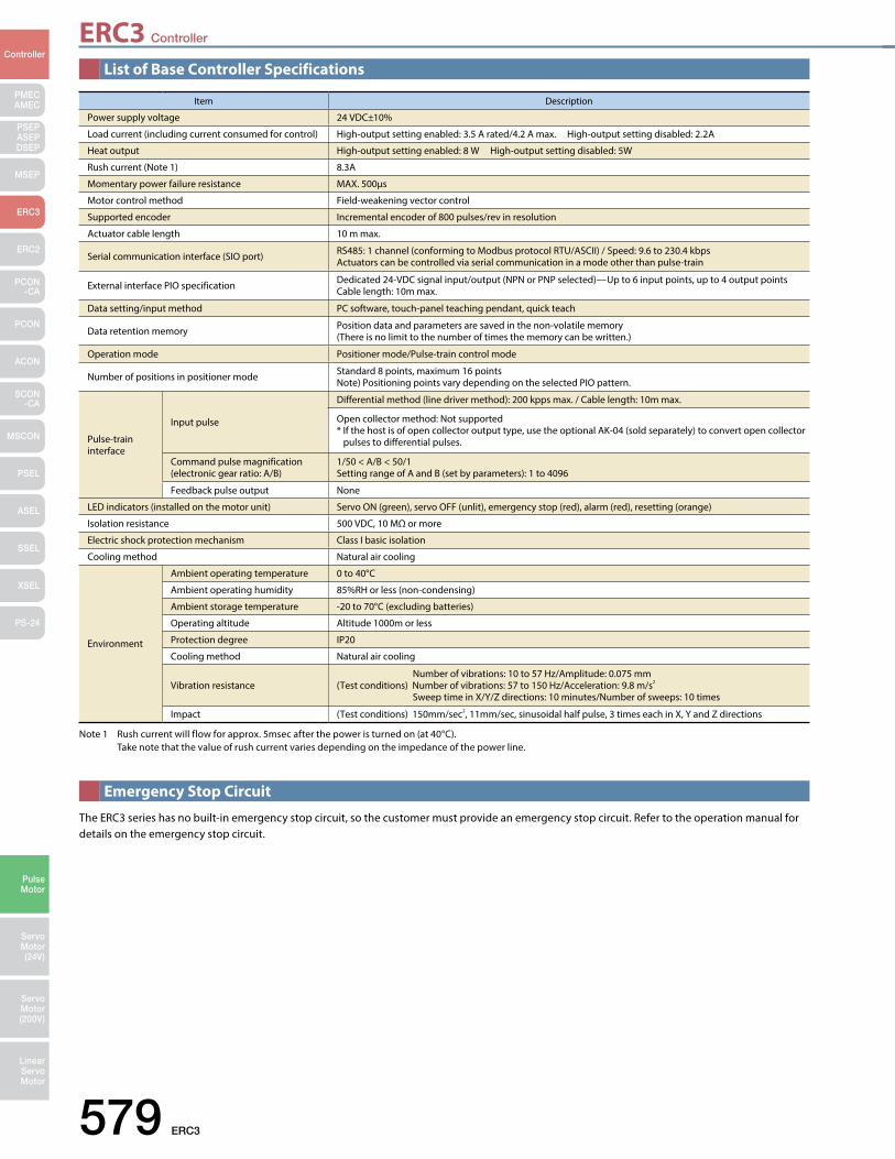
ERC3 Controller
579 ERC3
PMECAMEC
Controller
Pulse Motor
Servo Motor (24V)
Servo Motor (200V)
LinearServo Motor
PSEP ASEPDSEP
MSEP
ERC3
ERC2
PCON-CA
PCON
ACON
SCON-CA
MSCON
PSEL
ASEL
SSEL
XSEL
PS-24
Item Description
Power supply voltage 24 VDC±10%
Load current (including current consumed for control) High-output setting enabled: 3.5 A rated/4.2 A max. High-output setting disabled: 2.2A
Heat output High-output setting enabled: 8 W High-output setting disabled: 5W
Rush current (Note 1) 8.3A
Momentary power failure resistance MAX. 500μs
Motor control method Field-weakening vector control
Supported encoder Incremental encoder of 800 pulses/rev in resolution
Actuator cable length 10 m max.
Serial communication interface (SIO port) RS485: 1 channel (conforming to Modbus protocol RTU/ASCII) / Speed: 9.6 to 230.4 kbpsActuators can be controlled via serial communication in a mode other than pulse-train
External interface PIO specification Dedicated 24-VDC signal input/output (NPN or PNP selected)—Up to 6 input points, up to 4 output points Cable length: 10m max.
Data setting/input method PC software, touch-panel teaching pendant, quick teach
Data retention memory Position data and parameters are saved in the non-volatile memory (There is no limit to the number of times the memory can be written.)
Operation mode Positioner mode/Pulse-train control mode
Number of positions in positioner mode Standard 8 points, maximum 16 points Note) Positioning points vary depending on the selected PIO pattern.
Pulse-train interface
Input pulse
Differential method (line driver method): 200 kpps max. / Cable length: 10m max.
Open collector method: Not supported* If the host is of open collector output type, use the optional AK-04 (sold separately) to convert open collector pulses to differential pulses.
Command pulse magnification (electronic gear ratio: A/B)
1/50 < A/B < 50/1Setting range of A and B (set by parameters): 1 to 4096
Feedback pulse output None
LED indicators (installed on the motor unit) Servo ON (green), servo OFF (unlit), emergency stop (red), alarm (red), resetting (orange)
Isolation resistance 500 VDC, 10 MΩ or more
Electric shock protection mechanism Class I basic isolation
Cooling method Natural air cooling
Environment
Ambient operating temperature 0 to 40°C
Ambient operating humidity 85%RH or less (non-condensing)
Ambient storage temperature -20 to 70°C (excluding batteries)
Operating altitude Altitude 1000m or less
Protection degree IP20
Cooling method Natural air cooling
Vibration resistance Number of vibrations: 10 to 57 Hz/Amplitude: 0.075 mm (Test conditions) Number of vibrations: 57 to 150 Hz/Acceleration: 9.8 m/s2
Sweep time in X/Y/Z directions: 10 minutes/Number of sweeps: 10 times
Impact (Test conditions) 150mm/sec2, 11mm/sec, sinusoidal half pulse, 3 times each in X, Y and Z directions
List of Base Controller Specifications
Note 1 Rush current will flow for approx. 5msec after the power is turned on (at 40°C). Take note that the value of rush current varies depending on the impedance of the power line.
The ERC3 series has no built-in emergency stop circuit, so the customer must provide an emergency stop circuit. Refer to the operation manual for details on the emergency stop circuit.
Emergency Stop Circuit
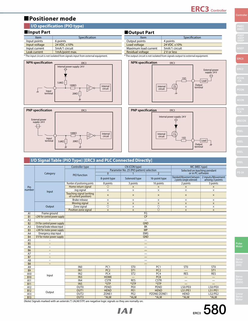
ERC3 Controller
ERC3 580
PMECAMEC
Controller
Pulse Motor
Servo Motor (24V)
Servo Motor (200V)
LinearServo Motor
PSEP ASEPDSEP
MSEP
ERC3
ERC2
PCON-CA
PCON
ACON
SCON-CA
MSCON
PSEL
ASEL
SSEL
XSEL
PS-24
NPN specification ERC3Internal power supply: 24 V
5.6KΩ100KΩ
20KΩInput
terminal
Internal circuit
NPN specification
External power supply: 24 V
15ΩLoad
Output terminal
ERC3
Internal circuit
PNP specification ERC3
5.6KΩ
100KΩ
20KΩInput
terminal
Internal circuit
External power supply: 24 V
PNP specification
Internal power supply: 24 V
15ΩLoad
Output terminal
ERC3
Internal circuit
Positioner modeI/O specification (PIO type)
I/O Signal Table (PIO Type) [ERC3 and PLC Connected Directly]
* The output circuit is not isolated from signals output to external equipment.* The input circuit is not isolated from signals input from external equipment.
Item SpecificationInput points 6 pointsInput voltage 24 VDC ±10%Input current 5mA/1 circuitLeak current 1mA/point max.
Item SpecificationOutput points 4 pointsLoad voltage 24 VDC ±10%Maximum load current 5mA/1 circuitResidual voltage 2 V or less
Input Part Output Part
Pin number
Category
Controller type CN (CON type) MC (MEC type)
PIO function
Parameter No. 25 (PIO pattern) selection Selected on teaching pendantor in PC software0 1 2
8-point type Solenoid type 16-point type Standard/Movement between 2 points (single solenoid)
2 inputs/Movement among 3 points
Input
Number of positioning points 8 points 3 points 16 points 2 points 3 pointsHome return signal × × × ×
Jog signal × × × × ×Teaching signal (writing
of current position) × × × × ×
Brake release × × × × ×
OutputMoving signal × × × × ×
Zone signal × × ×Position zone signal × × × ×
A1 Frame ground FGB1 +24V for control power supply CPA2 − —B2 0 V for control power supply GNDA3 External brake release input BKB3 +24V for motor power supply MPA4 Emergency stop input EMGB4 0 V for motor power supply GNDA5 − —B5 − —A6 − —B6 − —A7 − —B7 − —A8 − —B8 − —A9
Input
IN0 PC1 ST0 PC1 ST0 ST0B9 IN1 PC2 ST1 PC2 — ST1
A10 IN2 PC4 ST2 PC4 RES RESB10 IN3 HOME — PC8 — —A11 IN4 CSTR RES CSTR — —B11 IN5 *STP *STP *STP — —A12
Output
OUT0 PEND PE0 PEND LS0/PE0 LS0/PE0B12 OUT1 HEND PE1 HEND LS1/PE1 LS1/PE1A13 OUT2 ZONE1 PE2 PZONE/ZONE1 HEND LS2/PE2B13 OUT3 *ALM *ALM *ALM *ALM *ALM
(Note) Signals marked with an asterisk (*) (ALM/STP) are negative logic signals so they are nomally on.
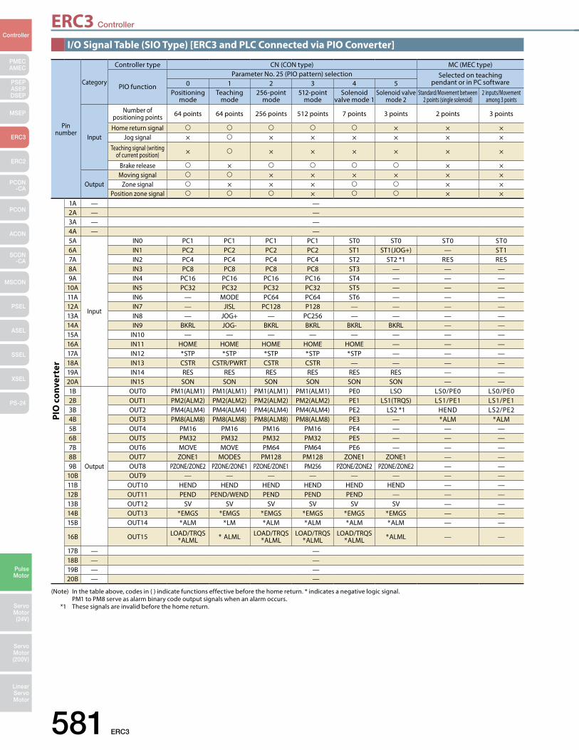
581 ERC3
PMECAMEC
Controller
Pulse Motor
Servo Motor (24V)
Servo Motor (200V)
LinearServo Motor
PSEP ASEPDSEP
MSEP
ERC3
ERC2
PCON-CA
PCON
ACON
SCON-CA
MSCON
PSEL
ASEL
SSEL
XSEL
PS-24
ERC3 Controller
Pin number
Category
Controller type CN (CON type) MC (MEC type)
PIO function
Parameter No. 25 (PIO pattern) selection Selected on teaching pendant or in PC software0 1 2 3 4 5
Positioning mode
Teaching mode
256-point mode
512-point mode
Solenoid valve mode 1
Solenoid valve mode 2
Standard/Movement between 2 points (single solenoid)
2 inputs/Movement among 3 points
Input
Number of positioning points 64 points 64 points 256 points 512 points 7 points 3 points 2 points 3 points
Home return signal × × ×Jog signal × × × × × × ×
Teaching signal (writing of current position) × × × × × × ×
Brake release × × ×
OutputMoving signal × × × × × ×
Zone signal × × × × ×Position zone signal × × ×
1A — —2A — —3A — —4A — —5A
Input
IN0 PC1 PC1 PC1 PC1 ST0 ST0 ST0 ST06A IN1 PC2 PC2 PC2 PC2 ST1 ST1(JOG+) — ST17A IN2 PC4 PC4 PC4 PC4 ST2 ST2 *1 RES RES8A IN3 PC8 PC8 PC8 PC8 ST3 — — —9A IN4 PC16 PC16 PC16 PC16 ST4 — — —
10A IN5 PC32 PC32 PC32 PC32 ST5 — — —11A IN6 — MODE PC64 PC64 ST6 — — —12A IN7 — JISL PC128 P128 — — — —13A IN8 — JOG+ — PC256 — — — —14A IN9 BKRL JOG- BKRL BKRL BKRL BKRL — —15A IN10 — — — — — — — —16A IN11 HOME HOME HOME HOME HOME — — —17A IN12 *STP *STP *STP *STP *STP — — —18A IN13 CSTR CSTR/PWRT CSTR CSTR — — — —19A IN14 RES RES RES RES RES RES — —20A IN15 SON SON SON SON SON SON — —1B
Output
OUT0 PM1(ALM1) PM1(ALM1) PM1(ALM1) PM1(ALM1) PE0 LSO LS0/PE0 LS0/PE02B OUT1 PM2(ALM2) PM2(ALM2) PM2(ALM2) PM2(ALM2) PE1 LS1(TRQS) LS1/PE1 LS1/PE13B OUT2 PM4(ALM4) PM4(ALM4) PM4(ALM4) PM4(ALM4) PE2 LS2 *1 HEND LS2/PE24B OUT3 PM8(ALM8) PM8(ALM8) PM8(ALM8) PM8(ALM8) PE3 — *ALM *ALM5B OUT4 PM16 PM16 PM16 PM16 PE4 — — —6B OUT5 PM32 PM32 PM32 PM32 PE5 — — —7B OUT6 MOVE MOVE PM64 PM64 PE6 — — —8B OUT7 ZONE1 MODES PM128 PM128 ZONE1 ZONE1 — —9B OUT8 PZONE/ZONE2 PZONE/ZONE1 PZONE/ZONE1 PM256 PZONE/ZONE2 PZONE/ZONE2 — —
10B OUT9 — — — — — — — —11B OUT10 HEND HEND HEND HEND HEND HEND — —12B OUT11 PEND PEND/WEND PEND PEND PEND — — —13B OUT12 SV SV SV SV SV SV — —14B OUT13 *EMGS *EMGS *EMGS *EMGS *EMGS *EMGS — —15B OUT14 *ALM *LM *ALM *ALM *ALM *ALM — —
16B OUT15 LOAD/TRQS*ALML * ALML LOAD/TRQS
*ALMLLOAD/TRQS
*ALMLLOAD/TRQS
*ALML *ALML — —
17B — —18B — —19B — —20B — —
PIO
con
vert
er
(Note) In the table above, codes in ( ) indicate functions effective before the home return. * indicates a negative logic signal. PM1 to PM8 serve as alarm binary code output signals when an alarm occurs. *1 These signals are invalid before the home return.
I/O Signal Table (SIO Type) [ERC3 and PLC Connected via PIO Converter]
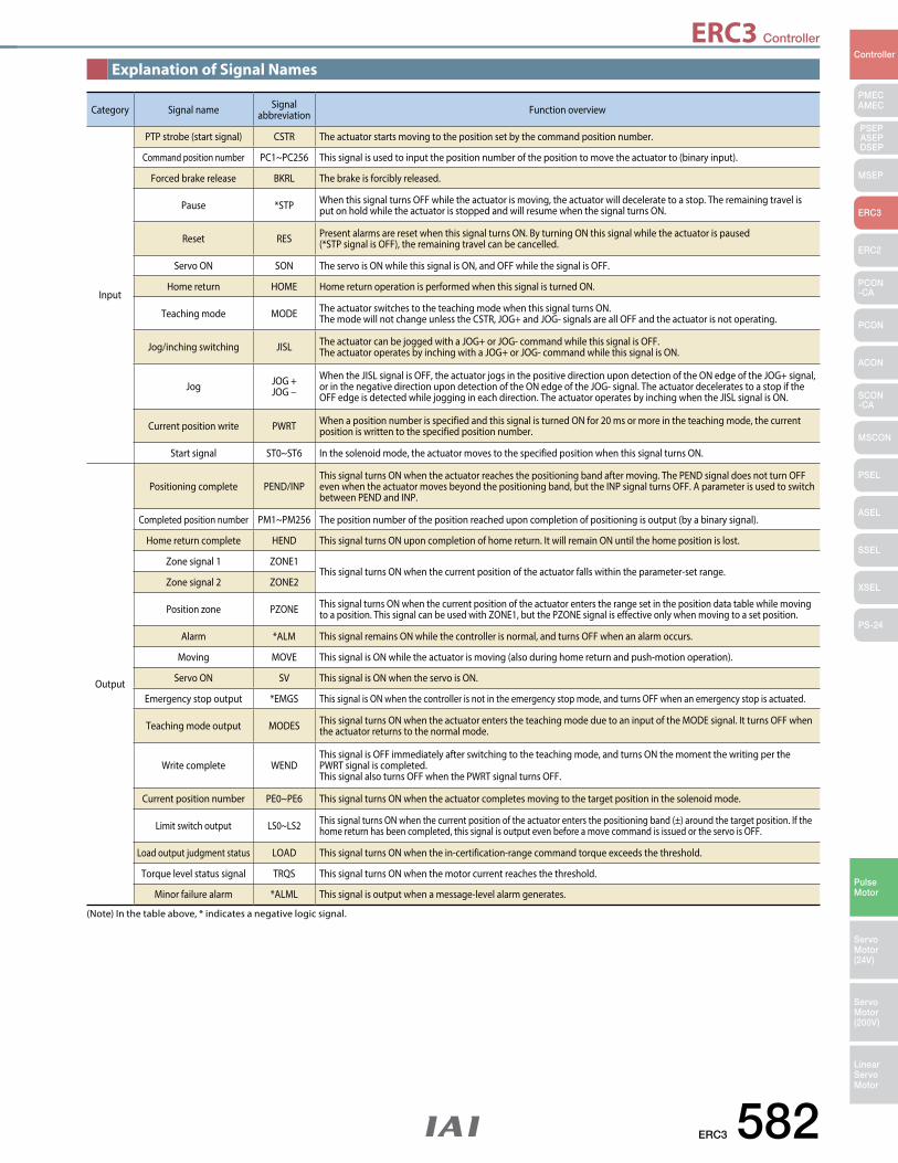
ERC3 582
PMECAMEC
Controller
Pulse Motor
Servo Motor (24V)
Servo Motor (200V)
LinearServo Motor
PSEP ASEPDSEP
MSEP
ERC3
ERC2
PCON-CA
PCON
ACON
SCON-CA
MSCON
PSEL
ASEL
SSEL
XSEL
PS-24
ERC3 Controller
Category Signal name Signal abbreviation Function overview
Input
PTP strobe (start signal) CSTR The actuator starts moving to the position set by the command position number.
Command position number PC1~PC256 This signal is used to input the position number of the position to move the actuator to (binary input).
Forced brake release BKRL The brake is forcibly released.
Pause *STP When this signal turns OFF while the actuator is moving, the actuator will decelerate to a stop. The remaining travel is put on hold while the actuator is stopped and will resume when the signal turns ON.
Reset RES Present alarms are reset when this signal turns ON. By turning ON this signal while the actuator is paused (*STP signal is OFF), the remaining travel can be cancelled.
Servo ON SON The servo is ON while this signal is ON, and OFF while the signal is OFF.
Home return HOME Home return operation is performed when this signal is turned ON.
Teaching mode MODE The actuator switches to the teaching mode when this signal turns ON. The mode will not change unless the CSTR, JOG+ and JOG- signals are all OFF and the actuator is not operating.
Jog/inching switching JISL The actuator can be jogged with a JOG+ or JOG- command while this signal is OFF. The actuator operates by inching with a JOG+ or JOG- command while this signal is ON.
Jog JOG +JOG −
When the JISL signal is OFF, the actuator jogs in the positive direction upon detection of the ON edge of the JOG+ signal, or in the negative direction upon detection of the ON edge of the JOG- signal. The actuator decelerates to a stop if the OFF edge is detected while jogging in each direction. The actuator operates by inching when the JISL signal is ON.
Current position write PWRT When a position number is specified and this signal is turned ON for 20 ms or more in the teaching mode, the current position is written to the specified position number.
Start signal ST0~ST6 In the solenoid mode, the actuator moves to the specified position when this signal turns ON.
Output
Positioning complete PEND/INPThis signal turns ON when the actuator reaches the positioning band after moving. The PEND signal does not turn OFF even when the actuator moves beyond the positioning band, but the INP signal turns OFF. A parameter is used to switch between PEND and INP.
Completed position number PM1~PM256 The position number of the position reached upon completion of positioning is output (by a binary signal).
Home return complete HEND This signal turns ON upon completion of home return. It will remain ON until the home position is lost.
Zone signal 1 ZONE1This signal turns ON when the current position of the actuator falls within the parameter-set range.
Zone signal 2 ZONE2
Position zone PZONE This signal turns ON when the current position of the actuator enters the range set in the position data table while moving to a position. This signal can be used with ZONE1, but the PZONE signal is effective only when moving to a set position.
Alarm *ALM This signal remains ON while the controller is normal, and turns OFF when an alarm occurs.
Moving MOVE This signal is ON while the actuator is moving (also during home return and push-motion operation).
Servo ON SV This signal is ON when the servo is ON.
Emergency stop output *EMGS This signal is ON when the controller is not in the emergency stop mode, and turns OFF when an emergency stop is actuated.
Teaching mode output MODES This signal turns ON when the actuator enters the teaching mode due to an input of the MODE signal. It turns OFF when the actuator returns to the normal mode.
Write complete WENDThis signal is OFF immediately after switching to the teaching mode, and turns ON the moment the writing per the PWRT signal is completed.This signal also turns OFF when the PWRT signal turns OFF.
Current position number PE0~PE6 This signal turns ON when the actuator completes moving to the target position in the solenoid mode.
Limit switch output LS0~LS2 This signal turns ON when the current position of the actuator enters the positioning band (±) around the target position. If the home return has been completed, this signal is output even before a move command is issued or the servo is OFF.
Load output judgment status LOAD This signal turns ON when the in-certification-range command torque exceeds the threshold.
Torque level status signal TRQS This signal turns ON when the motor current reaches the threshold.
Minor failure alarm *ALML This signal is output when a message-level alarm generates.
Explanation of Signal Names
(Note) In the table above, * indicates a negative logic signal.
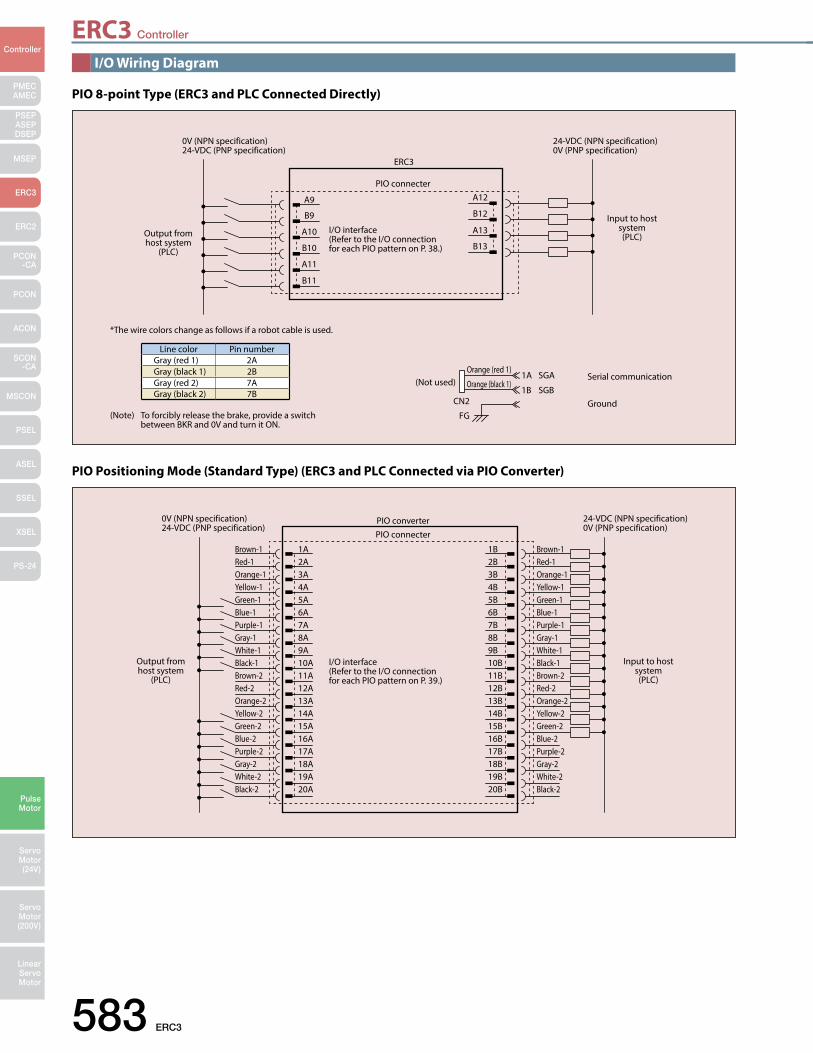
ERC3 Controller
583 ERC3
PMECAMEC
Controller
Pulse Motor
Servo Motor (24V)
Servo Motor (200V)
LinearServo Motor
PSEP ASEPDSEP
MSEP
ERC3
ERC2
PCON-CA
PCON
ACON
SCON-CA
MSCON
PSEL
ASEL
SSEL
XSEL
PS-24
ERC3
(Not used)Serial communication
GroundCN2
FG
1A SGA
1B SGB
Orange (red 1)
Orange (black 1)
PIO connecter
0V (NPN specification)24-VDC (PNP specification)
24-VDC (NPN specification)0V (PNP specification)
*The wire colors change as follows if a robot cable is used.
(Note) To forcibly release the brake, provide a switch between BKR and 0V and turn it ON.
I/O interface (Refer to the I/O connection for each PIO pattern on P. 38.)
A9
A10
A11
A12
A13
B13
B12
B11
B10
B9
Line color Pin numberGray (red 1) 2AGray (black 1) 2BGray (red 2) 7AGray (black 2) 7B
Input to host system(PLC)Output from
host system(PLC)
PIO connecterPIO converter
I/O interface (Refer to the I/O connection for each PIO pattern on P. 39.)
1A2A3A4A5A6A7A8A9A10A11A12A13A14A15A16A17A18A19A20A
1B2B3B4B5B6B7B8B9B10B11B12B13B14B15B16B17B18B19B20B
Brown-1Red-1Orange-1Yellow-1Green-1Blue-1Purple-1Gray-1White-1Black-1Brown-2Red-2Orange-2Yellow-2Green-2Blue-2Purple-2Gray-2White-2Black-2
Brown-1Red-1Orange-1Yellow-1Green-1Blue-1Purple-1Gray-1White-1Black-1Brown-2Red-2Orange-2Yellow-2Green-2Blue-2Purple-2Gray-2White-2Black-2
0V (NPN specification)24-VDC (PNP specification)
Output from host system
(PLC)
Input to host system(PLC)
24-VDC (NPN specification)0V (PNP specification)
I/O Wiring Diagram
PIO 8-point Type (ERC3 and PLC Connected Directly)
PIO Positioning Mode (Standard Type) (ERC3 and PLC Connected via PIO Converter)
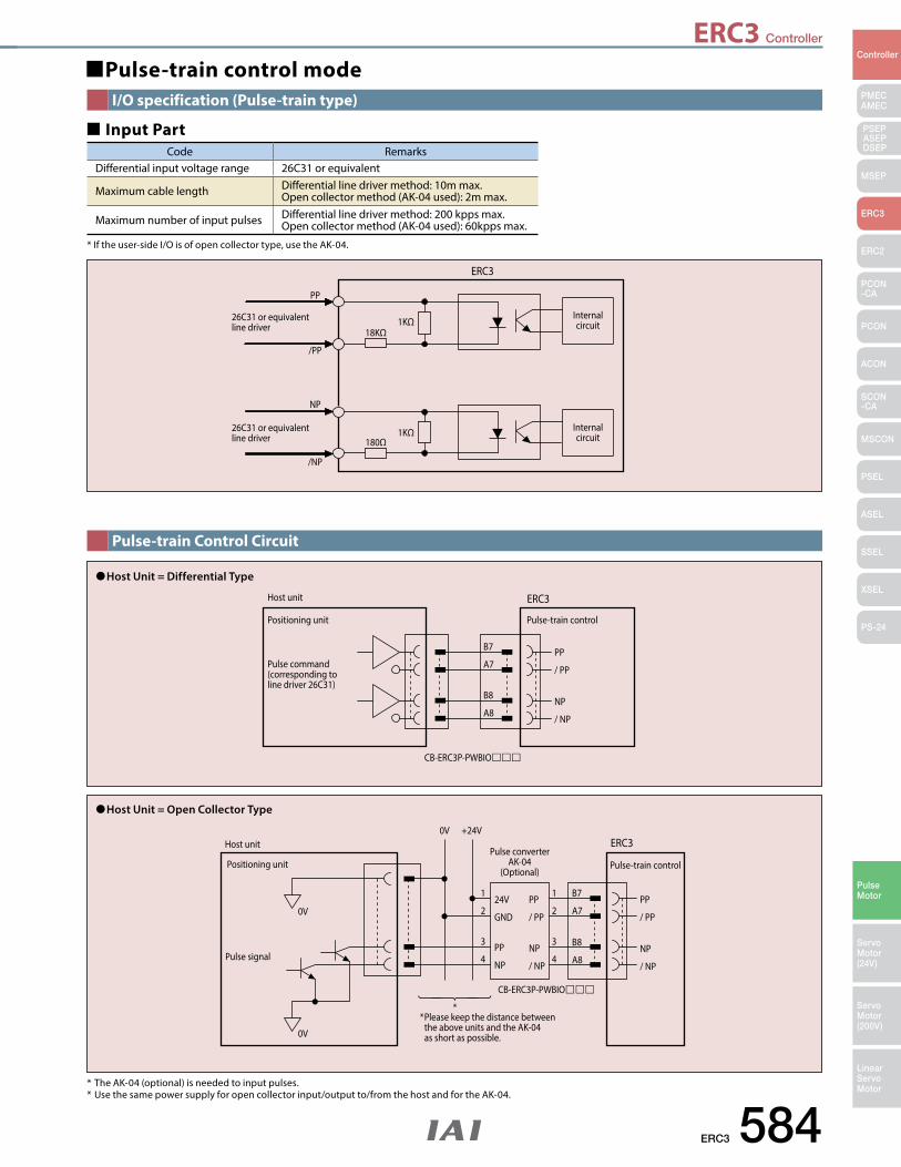
ERC3 Controller
ERC3 584
PMECAMEC
Controller
Pulse Motor
Servo Motor (24V)
Servo Motor (200V)
LinearServo Motor
PSEP ASEPDSEP
MSEP
ERC3
ERC2
PCON-CA
PCON
ACON
SCON-CA
MSCON
PSEL
ASEL
SSEL
XSEL
PS-24
ERC3
Internal circuit
Internal circuit
18KΩ
26C31 or equivalent line driver
26C31 or equivalent line driver
PP
/PP
/NP
NP
180Ω
1KΩ
1KΩ
Pulse-train control modeI/O specification (Pulse-train type)
Pulse-train Control Circuit
Code RemarksDifferential input voltage range 26C31 or equivalent
Maximum cable length Differential line driver method: 10m max. Open collector method (AK-04 used): 2m max.
Maximum number of input pulses Differential line driver method: 200 kpps max. Open collector method (AK-04 used): 60kpps max.
Input Part
* If the user-side I/O is of open collector type, use the AK-04.
ERC3Host unit
CB-ERC3P-PWBIO
Positioning unit Pulse-train control
Pulse command (corresponding to line driver 26C31)
B7 PP
/ PP
NP
/ NP
B8
A8
A7
Host Unit = Differential Type
* The AK-04 (optional) is needed to input pulses. * Use the same power supply for open collector input/output to/from the host and for the AK-04.
ERC3Host unit
0V
0V
Pulse signal
CB-ERC3P-PWBIO
Positioning unitPulse converter
AK-04(Optional)
Pulse-train control
B7
B8
PP
/ PP
PP
/ PP
24V
GND
PP
NP
1
2
1
2
3
4
3
4NP
/ NP
NP
/ NP
A7
A8
+24V0V
Host Unit = Open Collector Type
* Please keep the distance between the above units and the AK-04 as short as possible.
*
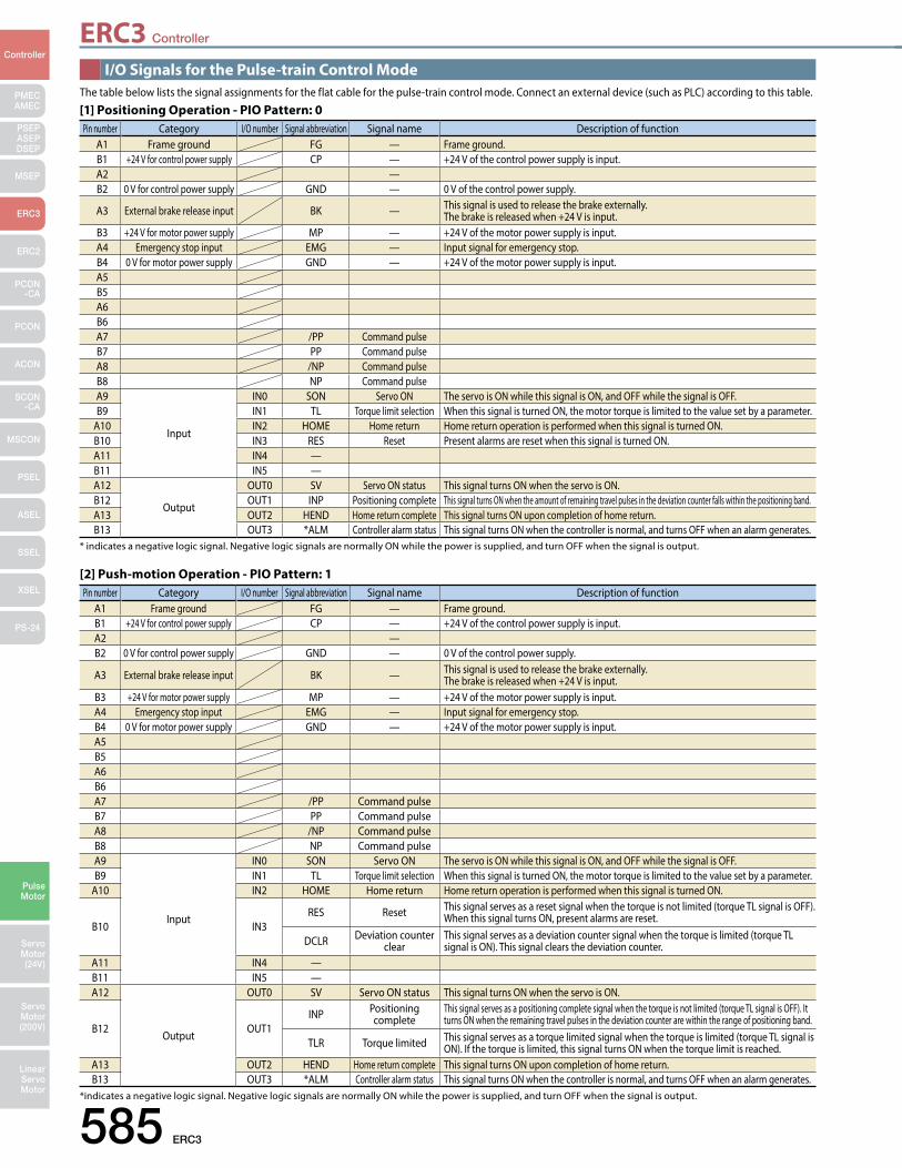
ERC3 Controller
585 ERC3
PMECAMEC
Controller
Pulse Motor
Servo Motor (24V)
Servo Motor (200V)
LinearServo Motor
PSEP ASEPDSEP
MSEP
ERC3
ERC2
PCON-CA
PCON
ACON
SCON-CA
MSCON
PSEL
ASEL
SSEL
XSEL
PS-24
Pin number Category I/O number Signal abbreviation Signal name Description of function A1 Frame ground FG — Frame ground. B1 +24 V for control power supply CP — +24 V of the control power supply is input.A2 —B2 0 V for control power supply GND — 0 V of the control power supply.
A3 External brake release input BK — This signal is used to release the brake externally. The brake is released when +24 V is input.
B3 +24 V for motor power supply MP — +24 V of the motor power supply is input.A4 Emergency stop input EMG — Input signal for emergency stop.B4 0 V for motor power supply GND — +24 V of the motor power supply is input.A5B5A6B6A7 /PP Command pulseB7 PP Command pulseA8 /NP Command pulseB8 NP Command pulseA9
Input
IN0 SON Servo ON The servo is ON while this signal is ON, and OFF while the signal is OFF.B9 IN1 TL Torque limit selection When this signal is turned ON, the motor torque is limited to the value set by a parameter.
A10 IN2 HOME Home return Home return operation is performed when this signal is turned ON.
B10 IN3RES Reset This signal serves as a reset signal when the torque is not limited (torque TL signal is OFF).
When this signal turns ON, present alarms are reset.
DCLR Deviation counter clear
This signal serves as a deviation counter signal when the torque is limited (torque TL signal is ON). This signal clears the deviation counter.
A11 IN4 —B11 IN5 —A12
Output
OUT0 SV Servo ON status This signal turns ON when the servo is ON.
B12 OUT1INP Positioning
completeThis signal serves as a positioning complete signal when the torque is not limited (torque TL signal is OFF). It turns ON when the remaining travel pulses in the deviation counter are within the range of positioning band.
TLR Torque limited This signal serves as a torque limited signal when the torque is limited (torque TL signal is ON). If the torque is limited, this signal turns ON when the torque limit is reached.
A13 OUT2 HEND Home return complete This signal turns ON upon completion of home return.B13 OUT3 *ALM Controller alarm status This signal turns ON when the controller is normal, and turns OFF when an alarm generates.
Pin number Category I/O number Signal abbreviation Signal name Description of function A1 Frame ground FG — Frame ground.B1 +24 V for control power supply CP — +24 V of the control power supply is input.A2 —B2 0 V for control power supply GND — 0 V of the control power supply.
A3 External brake release input BK — This signal is used to release the brake externally. The brake is released when +24 V is input.
B3 +24 V for motor power supply MP — +24 V of the motor power supply is input. A4 Emergency stop input EMG — Input signal for emergency stop.B4 0 V for motor power supply GND — +24 V of the motor power supply is input.A5B5A6B6A7 /PP Command pulseB7 PP Command pulseA8 /NP Command pulseB8 NP Command pulseA9
Input
IN0 SON Servo ON The servo is ON while this signal is ON, and OFF while the signal is OFF.B9 IN1 TL Torque limit selection When this signal is turned ON, the motor torque is limited to the value set by a parameter.
A10 IN2 HOME Home return Home return operation is performed when this signal is turned ON.B10 IN3 RES Reset Present alarms are reset when this signal is turned ON.A11 IN4 —B11 IN5 —A12
Output
OUT0 SV Servo ON status This signal turns ON when the servo is ON.B12 OUT1 INP Positioning complete This signal turns ON when the amount of remaining travel pulses in the deviation counter falls within the positioning band.A13 OUT2 HEND Home return complete This signal turns ON upon completion of home return.B13 OUT3 *ALM Controller alarm status This signal turns ON when the controller is normal, and turns OFF when an alarm generates.
I/O Signals for the Pulse-train Control Mode
[2] Push-motion Operation - PIO Pattern: 1
*indicates a negative logic signal. Negative logic signals are normally ON while the power is supplied, and turn OFF when the signal is output.
[1] Positioning Operation - PIO Pattern: 0
* indicates a negative logic signal. Negative logic signals are normally ON while the power is supplied, and turn OFF when the signal is output.
The table below lists the signal assignments for the flat cable for the pulse-train control mode. Connect an external device (such as PLC) according to this table.
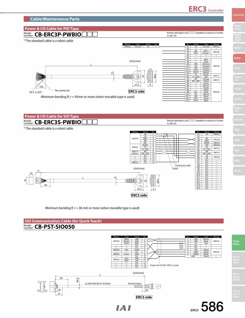
ERC3 Controller
ERC3 586
PMECAMEC
Controller
Pulse Motor
Servo Motor (24V)
Servo Motor (200V)
LinearServo Motor
PSEP ASEPDSEP
MSEP
ERC3
ERC2
PCON-CA
PCON
ACON
SCON-CA
MSCON
PSEL
ASEL
SSEL
XSEL
PS-24
Minimum bending R: r = 45mm or more (when movable type is used)
Cable/Maintenance Parts
ERC3 side
2
12
1
13
50
2530(3)
4.8
UL2990 AWG26 6C (K) Black (Panduit label)
Single wire (UL1061 AWG 16, gray)
120Ω1/4W
L(Unit/mm)
No. Signal Color Wiring1 SGA Brown
AWG262 SGB Black3 5V Red4 N.C —5 N.C —6 24V Yellow
AWG267 GND Green8 EMGB White
GND Shield —
Wiring Color Signal No.
AWG26Black SGB 1
Brown SGA 2White EMG 3
— — N.C 4— — N.C 5
AWG26 Red TGND 6— − N.C 7
AWG26 Green GND 8— − N.C 9
AWG26 Gray GND 10Blue 24V 11
— — N.C 12— — N.C 13— — N.C 14
CB-PST-SIO050Model number
SIO Communication Cable (for Quick Teach)
ERC3 side
9
B A
23.3
7.5
33 28.6
150
V0.5-3 (JST)No connector
L(Unit/mm)
Wiring Color Signal No.AWG22 Ground FG 1
Power & I/O Cable for PIO Type
CB-ERC3P-PWBIOModel number
* The standard cable is a robot cable.No. Signal Color WiringA1 FG Ground AWG22A2 — — —A3 BK Red 1 AWG28A4 EMG Orange 1A5 — — —A6 — — —A7 — Blue
AWG28
A8 — GrayA9 IN0 Brown2
A10 IN2 Orange2A11 IN4 Green2A12 OUT0 Purple2A13 OUT2 White2B1 CP Brown AWG22B2 CP_GND RedB3 MP Orange AWG19B4 MP_GND YellowB5 — Green
AWG28
B6 — Brown1B7 — PurpleB8 — WhiteB9 IN1 Red2
B10 IN3 Yellow2B11 IN5 Blue2B12 OUT1 Gray2B13 OUT3 Black
* Enter the cable length (L) into. Compatible to a maximum of 10 meters. Ex.: 080 = 8m
ERC3 side
Minimum bending R: r = 36 mm or more (when movable type is used)
Twisted pair cableShield
Wiring Signal No.
AWG28
SB 1SA 2
EMG 3BK 4
BAT 5
AWG22BGND 6
CP 7CP_GND 8
AWG19(AWG22)
MP 9MP_GND 10
— N.C 11— N.C 12— N.C 13
AWG22 FG 14
No. Signal WiringA1 FG AWG22A2 − −A3 BK AWG28A4 EMGA5 BGND AWG22A6 BAT AWG28B1 CP AWG22B2 CP_GNDB3 MP AWG19B4 MP_GNDB5 SA AWG28B6 SBA7 N.C —B7 N.C —A8 N.C —B8 N.C —A9 N.C —B9 N.C —
A10 N.C —B10 N.C —A11 N.C —B11 N.C —A12 N.C —B12 N.C —A13 N.C —B13 N.C —
6
923.3
33
L
(Unit/mm)
28.6
60
1110
16
CB-ERC3S-PWBIOModel number
Power & I/O Cable for SIO Type
* The standard cable is a robot cable.
* Enter the cable length (L) into. Compatible to a maximum of 10 meters. Ex.: 080 = 8m
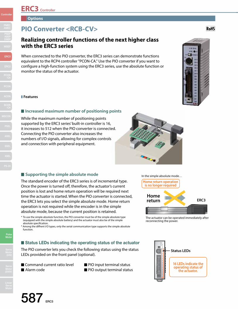
ERC3 Controller
587 ERC3
PMECAMEC
Controller
Pulse Motor
Servo Motor (24V)
Servo Motor (200V)
LinearServo Motor
PSEP ASEPDSEP
MSEP
ERC3
ERC2
PCON-CA
PCON
ACON
SCON-CA
MSCON
PSEL
ASEL
SSEL
XSEL
PS-24
PIO Converter <RCB-CV>
Features
When connected to the PIO converter, the ERC3 series can demonstrate functions equivalent to the RCP4 controller "PCON-CA." Use the PIO converter if you want to configure a high-function system using the ERC3 series, use the absolute function or monitor the status of the actuator.
Realizing controller functions of the next higher class with the ERC3 series
Options
Increased maximum number of positioning points
While the maximum number of positioning points supported by the ERC3 series’ built-in controller is 16, it increases to 512 when the PIO converter is connected.Connecting the PIO converter also increases the numbers of I/O signals, allowing for complex controls and connection with peripheral equipment.
Supporting the simple absolute mode The standard encoder of the ERC3 series is of incremental type. Once the power is turned off, therefore, the actuator’s current position is lost and home return operation will be required next time the actuator is started. When the PIO converter is connected, the ERC3 lets you select the simple absolute mode. Home return operation is not required while the encoder is in the simple absolute mode, because the current position is retained.* To use the simple absolute function, the PIO converter must be of the simple absolute type (equipped with the simple absolute battery) and the actuator must also be of the simple absolute specification. * Among the diffrent I/O types, only the serial communication type supports the simple absolute function.
Status LEDs indicating the operating status of the actuator The PIO converter lets you check the following status using the status LEDs provided on the front panel (optional).
Command current ratio level PIO input terminal status Alarm code PIO output terminal status
ERC3Home return
Home return operation is no longer required
In the simple absolute mode…
The actuator can be operated immediately after reconnecting the power.
Status LEDs
16 LEDs indicate the operating status of
the actuator.
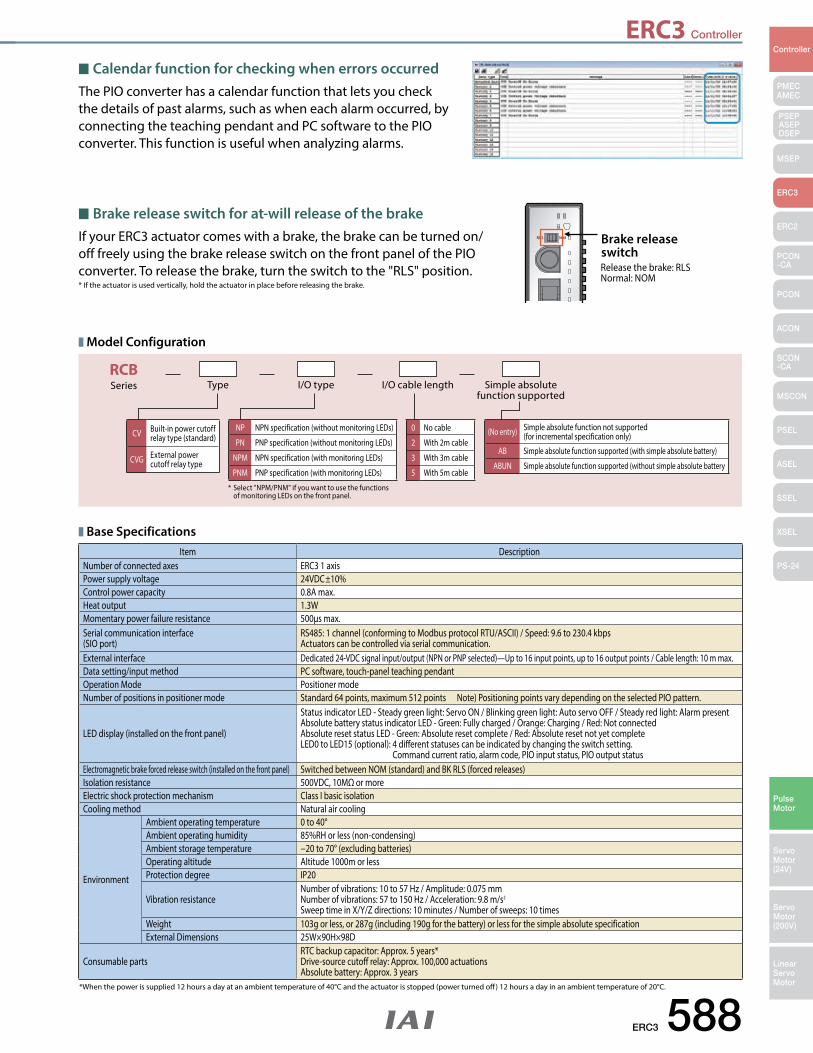
ERC3 Controller
ERC3 588
PMECAMEC
Controller
Pulse Motor
Servo Motor (24V)
Servo Motor (200V)
LinearServo Motor
PSEP ASEPDSEP
MSEP
ERC3
ERC2
PCON-CA
PCON
ACON
SCON-CA
MSCON
PSEL
ASEL
SSEL
XSEL
PS-24
NOMRLS
RCBSeries Type I/O type I/O cable length Simple absolute
function supported
CV Built-in power cutoff relay type (standard)
CVG External power cutoff relay type
NP NPN specification (without monitoring LEDs)
PN PNP specification (without monitoring LEDs)
NPM NPN specification (with monitoring LEDs)
PNM PNP specification (with monitoring LEDs)
0 No cable
2 With 2m cable
3 With 3m cable
5 With 5m cable
(No entry) Simple absolute function not supported (for incremental specification only)
AB Simple absolute function supported (with simple absolute battery)
ABUN Simple absolute function supported (without simple absolute battery
* Select "NPM/PNM" if you want to use the functions of monitoring LEDs on the front panel.
Item DescriptionNumber of connected axes ERC3 1 axisPower supply voltage 24VDC±10%Control power capacity 0.8A max.Heat output 1.3WMomentary power failure resistance 500μs max.Serial communication interface(SIO port)
RS485: 1 channel (conforming to Modbus protocol RTU/ASCII) / Speed: 9.6 to 230.4 kbpsActuators can be controlled via serial communication.
External interface Dedicated 24-VDC signal input/output (NPN or PNP selected)—Up to 16 input points, up to 16 output points / Cable length: 10 m max.Data setting/input method PC software, touch-panel teaching pendantOperation Mode Positioner modeNumber of positions in positioner mode Standard 64 points, maximum 512 points Note) Positioning points vary depending on the selected PIO pattern.
LED display (installed on the front panel)
Status indicator LED - Steady green light: Servo ON / Blinking green light: Auto servo OFF / Steady red light: Alarm present Absolute battery status indicator LED - Green: Fully charged / Orange: Charging / Red: Not connectedAbsolute reset status LED - Green: Absolute reset complete / Red: Absolute reset not yet complete LED0 to LED15 (optional): 4 different statuses can be indicated by changing the switch setting. Command current ratio, alarm code, PIO input status, PIO output status
Electromagnetic brake forced release switch (installed on the front panel) Switched between NOM (standard) and BK RLS (forced releases)Isolation resistance 500VDC, 10MΩ or moreElectric shock protection mechanism Class I basic isolationCooling method Natural air cooling
Environment
Ambient operating temperature 0 to 40°Ambient operating humidity 85%RH or less (non-condensing)Ambient storage temperature −20 to 70° (excluding batteries)Operating altitude Altitude 1000m or lessProtection degree IP20
Vibration resistanceNumber of vibrations: 10 to 57 Hz / Amplitude: 0.075 mm Number of vibrations: 57 to 150 Hz / Acceleration: 9.8 m/s2 Sweep time in X/Y/Z directions: 10 minutes / Number of sweeps: 10 times
Weight 103g or less, or 287g (including 190g for the battery) or less for the simple absolute specificationExternal Dimensions 25W×90H×98D
Consumable partsRTC backup capacitor: Approx. 5 years*Drive-source cutoff relay: Approx. 100,000 actuationsAbsolute battery: Approx. 3 years
Base Specifications
*When the power is supplied 12 hours a day at an ambient temperature of 40°C and the actuator is stopped (power turned off ) 12 hours a day in an ambient temperature of 20°C.
Model Configuration
Brake release switch for at-will release of the brakeIf your ERC3 actuator comes with a brake, the brake can be turned on/off freely using the brake release switch on the front panel of the PIO converter. To release the brake, turn the switch to the "RLS" position.* If the actuator is used vertically, hold the actuator in place before releasing the brake.
Brake release switchRelease the brake: RLSNormal: NOM
Calendar function for checking when errors occurredThe PIO converter has a calendar function that lets you check the details of past alarms, such as when each alarm occurred, by connecting the teaching pendant and PC software to the PIO converter. This function is useful when analyzing alarms.
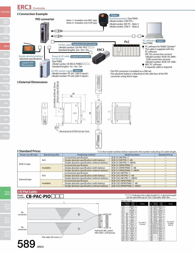
ERC3 Controller
589 ERC3
PMECAMEC
Controller
Pulse Motor
Servo Motor (24V)
Servo Motor (200V)
LinearServo Motor
PSEP ASEPDSEP
MSEP
ERC3
ERC2
PCON-CA
PCON
ACON
SCON-CA
MSCON
PSEL
ASEL
SSEL
XSEL
PS-24
No. Signal name
Cable color Wiring
1A - Brown - 1
Flat cable A (crimped)
2A - Red - 13A - Orange - 14A - Yellow - 15A IN0 Green - 16A IN1 Blue - 17A IN2 Purple - 18A IN3 Gray - 19A IN4 White - 1
10A IN5 Black - 111A IN6 Brown - 212A IN7 Red - 213A IN8 Orange - 214A IN9 Yellow - 215A IN10 Green - 216A IN11 Blue - 217A IN12 Purple - 218A IN13 Gray - 219A IN14 White - 220A IN15 Black - 2
No. Signal name
Cable color Wiring
1B OUT0 Brown - 3
Flat cable B (crimped)AWG 28
2B OUT1 Red - 33B OUT2 Orange - 34B OUT3 Yellow - 35B OUT4 Green - 36B OUT5 Blue - 37B OUT6 Purple - 38B OUT7 Gray - 39B OUT8 White - 3
10B OUT9 Black - 311B OUT10 Brown - 412B OUT11 Red - 413B OUT12 Orange - 414B OUT13 Yellow - 415B OUT14 Green - 416B OUT15 Blue - 417B — Purple - 418B — Gray - 419B — White - 420B — Black - 4
HIF6-40D-1.27RL
20A
1A
20B
1B
No connector
No connector
Flat cable (20 cores) x 2
Half-pitch MIL socket: HIF6-40D-1.27R (Hirose)
A
B
*indicates the cable length (L). A desired length can be specified up to 10m. Example: 080=8mCB-PAC-PIOModel
number
I/O Flat Cable
Standard PricesPower cut-off relay Monitoring LEDs Positoning method Model Numbers Standard Prices
Built-in type
N/AIncremental specification RCB-CV-(NP/PN)-➀ —Simple absolute specification (with battery) RCB-CV-(NP/PN)-➀ -AB —Simple absolute specification (without battery) RCB-CV-(NP/PN)-➀ -ABUN —
AvailableIncremental specification RCB-CV-(NPM/PNM)-➀ —Simple absolute specification (with battery) RCB-CV-(NPM/PNM)-➀ -AB —Simple absolute specification (without battery) RCB-CV-(NPM/PNM)-➀ -ABUN —
External type
N/AIncremental specification RCB-CVG-(NP/PN)-➀ —Simple absolute specification (with battery) RCB-CVG-(NP/PN)-➀ -AB —Simple absolute specification (without battery) RCB-CVG-(NP/PN)-➀ -ABUN —
AvailableIncremental specification RCB-CVG-(NPM/PNM)-➀ —Simple absolute specification (with battery) RCB-CVG-(NPM/PNM)-➀ -AB —Simple absolute specification (without battery) RCB-CVG-(NPM/PNM)-➀ -ABUN —
*➀ in the model numbers below represents the number indicating I/O cable length.
98
25
90
35.4
(Wid
th o
f DIN
rail:
35m
m)
40 fr
om ce
nter
of D
IN ra
il (5
)(1
0)
80
Moving band of DIN lock tab: 5mm
4
Connection Example
External Dimensions
Option
Simple absolute battery(absolute specification)
I/O flat cable<Model number: CB-PAC-PIO>Standard lengths: 2m / 3m / 5m
24-VDC power supply <Model number: PS-241 (100-V input)><Model number: PS-242 (200-V input)>
•ThePIOconverterisinstalledonaDINrail.•TheabsolutebatteryisattachedonthesidefaceofthePIO converter using Velcro tape.
PC software (See P596) PC software for ROBO Cylinder® * The cable is supplied with the PC software. (RS 232 connection version) <Model number: RCM-101-MW> (USB connection version) <Model number: RCM-101-USB> MEC PC software * A separate cable is required.
Teaching pendant (See P605)<Model number: CON-PTA ><Model number: SEP-PT> (Note 1)<Model number: CON-T> (Note 2)
PIO converter
PLC
ERC3
Power & I/O cable for SIO type(See P586)<Model number: CB-ERC3S-PWBIO>Standard lengths: 1m / 3m / 5m
Option
Option
Supplied with PIO converter
Supplied with PIO converter
Supplied with Actuator
(Note 1) Available only MEC type(Note 2) Available only CON type
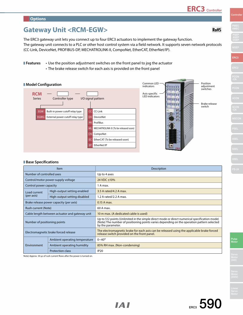
ERC3 Controller
ERC3 590
PMECAMEC
Controller
Pulse Motor
Servo Motor (24V)
Servo Motor (200V)
LinearServo Motor
PSEP ASEPDSEP
MSEP
ERC3
ERC2
PCON-CA
PCON
ACON
SCON-CA
MSCON
PSEL
ASEL
SSEL
XSEL
PS-24
Features •Usethepositionadjustmentswitchesonthefrontpaneltojogtheactuator •Thebrakereleaseswitchforeachaxisisprovidedonthefrontpanel
RCMSeries Controller type I/O signal pattern
Model Configuration
The ERC3 gateway unit lets you connect up to four ERC3 actuators to implement the gateway function. The gateway unit connects to a PLC or other host control system via a field network. It supports seven network protocols (CC-Link, DeviceNet, PROFIBUS-DP, MECHATROLINK-II, CompoNet, EtherCAT, EtherNet/IP).
Gateway Unit <RCM-EGW>
Base Specifications
Note) Approx. 50 μs of rush current flows after the power is turned on.
Item Description
Number of controlled axes Up to 4 axes
Control/motor power-supply voltage 24 VDC ±10%
Control power capacity 1 A max.
Load current (per axis)
High-output setting enabled 3.5 A rated/4.2 A max.
High-output setting disabled 1.2 A rated/2.2 A max.
Brake release power capacity (per axis) 0.15 A max.
Rush current (Note) 60 A max.
Cable length between actuator and gateway unit 10 m max. (A dedicated cable is used)
Number of positioning pointsUp to 512 points (Unlimited in the simple direct mode or direct numerical specification mode)(Note) The number of positioning points varies depending on the operation pattern selected by the parameter.
Electromagnetic brake forced release The electromagnetic brake for each axis can be released using the applicable brake forced release switch provided on the front panel.
Environment
Ambient operating temperature 0~40o
Ambient operating humidity 85% RH max. (Non-condensing)
Protection class IP20
EGW Built-in power cutoff relay type
EGWG External power cutoff relay type
CC CC-Link
DV DeviceNet
PR ProfiBus
ML MECHATROLINK-II (To be released soon)
CN CompoNet
EC EtherCAT (To be released soon)
EP EtherNet/IP
Options
Common LED indicators
Position adjustment switches
Brake release switch
Axis-specific LED indicators
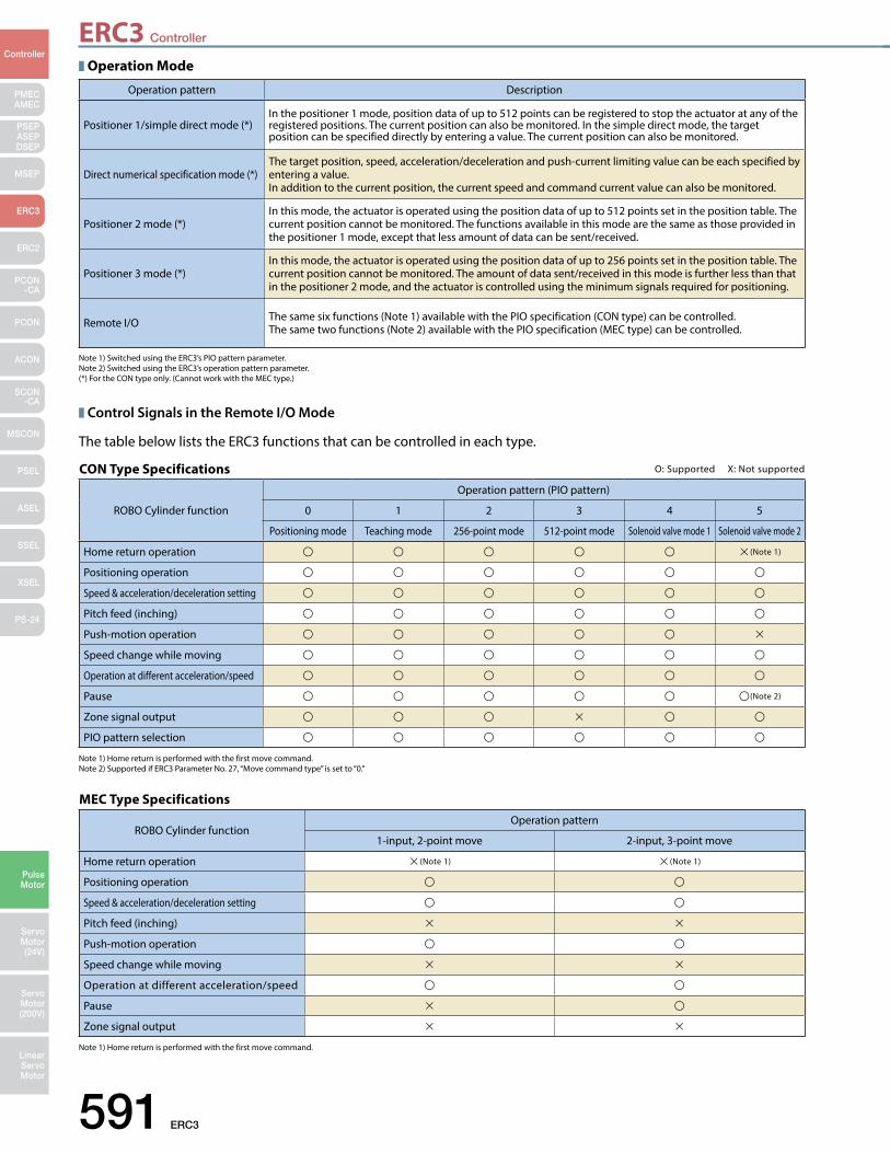
ERC3 Controller
591 ERC3
PMECAMEC
Controller
Pulse Motor
Servo Motor (24V)
Servo Motor (200V)
LinearServo Motor
PSEP ASEPDSEP
MSEP
ERC3
ERC2
PCON-CA
PCON
ACON
SCON-CA
MSCON
PSEL
ASEL
SSEL
XSEL
PS-24
CON Type Specifications O: Supported X: Not supported
ROBO Cylinder function
Operation pattern (PIO pattern)
0 1 2 3 4 5
Positioning mode Teaching mode 256-point mode 512-point mode Solenoid valve mode 1 Solenoid valve mode 2
Home return operation (Note 1)
Positioning operation
Speed & acceleration/deceleration setting
Pitch feed (inching)
Push-motion operation
Speed change while moving
Operation at different acceleration/speed
Pause (Note 2)
Zone signal output
PIO pattern selection
MEC Type Specifications
ROBO Cylinder functionOperation pattern
1-input, 2-point move 2-input, 3-point move
Home return operation (Note 1) (Note 1)
Positioning operation
Speed & acceleration/deceleration setting
Pitch feed (inching)
Push-motion operation
Speed change while moving
Operation at different acceleration/speed
Pause
Zone signal output
Operation Mode
Control Signals in the Remote I/O Mode
Note 1) Switched using the ERC3’s PIO pattern parameter. Note 2) Switched using the ERC3’s operation pattern parameter.(*) For the CON type only. (Cannot work with the MEC type.)
Note 1) Home return is performed with the first move command. Note 2) Supported if ERC3 Parameter No. 27, “Move command type” is set to “0.”
Note 1) Home return is performed with the first move command.
Operation pattern Description
Positioner 1/simple direct mode (*)In the positioner 1 mode, position data of up to 512 points can be registered to stop the actuator at any of the registered positions. The current position can also be monitored. In the simple direct mode, the target position can be specified directly by entering a value. The current position can also be monitored.
Direct numerical specification mode (*)The target position, speed, acceleration/deceleration and push-current limiting value can be each specified by entering a value. In addition to the current position, the current speed and command current value can also be monitored.
Positioner 2 mode (*)In this mode, the actuator is operated using the position data of up to 512 points set in the position table. The current position cannot be monitored. The functions available in this mode are the same as those provided in the positioner 1 mode, except that less amount of data can be sent/received.
Positioner 3 mode (*)In this mode, the actuator is operated using the position data of up to 256 points set in the position table. The current position cannot be monitored. The amount of data sent/received in this mode is further less than that in the positioner 2 mode, and the actuator is controlled using the minimum signals required for positioning.
Remote I/O The same six functions (Note 1) available with the PIO specification (CON type) can be controlled. The same two functions (Note 2) available with the PIO specification (MEC type) can be controlled.
The table below lists the ERC3 functions that can be controlled in each type.
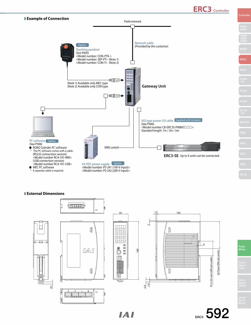
ERC3 Controller
ERC3 592
PMECAMEC
Controller
Pulse Motor
Servo Motor (24V)
Servo Motor (200V)
LinearServo Motor
PSEP ASEPDSEP
MSEP
ERC3
ERC2
PCON-CA
PCON
ACON
SCON-CA
MSCON
PSEL
ASEL
SSEL
XSEL
PS-24
35 105
140
4
65 fr
om D
IN ra
il ce
nter
35.4
(35-
mm
DIN
rail
wid
th)
(3)
(5)
21.
95.
9
Example of Connection
External Dimensions
Field network
EMG switch
Network cable (Provided by the customer)
Gateway Unit
ERC3-SE Up to 4 units can be connected.
PC software (See P596) ROBO Cylinder PC software * The PC software comes with a cable. (RS232 connection version) <Model number RCA-101-MW> (USB connection version) <Model number RCA-101-USB> MEC PC software * A separate cable is required.
Option
24-VDC power supply <Model number: PS-241 (100-V input)><Model number: PS-242 (200-V input)>
Option
Teaching pendant(See P605)<Model number: CON-PTA ><Model number: SEP-PT> (Note 1)<Model number: CON-T> (Note 2)
Option
SIO type power I/O cable(See P586) <Model number CB-ERC3S-PWBIO>Standard length: 1m / 3m / 5m
Supplied with Actuator
(Note 1) Available only MEC type(Note 2) Available only CON type
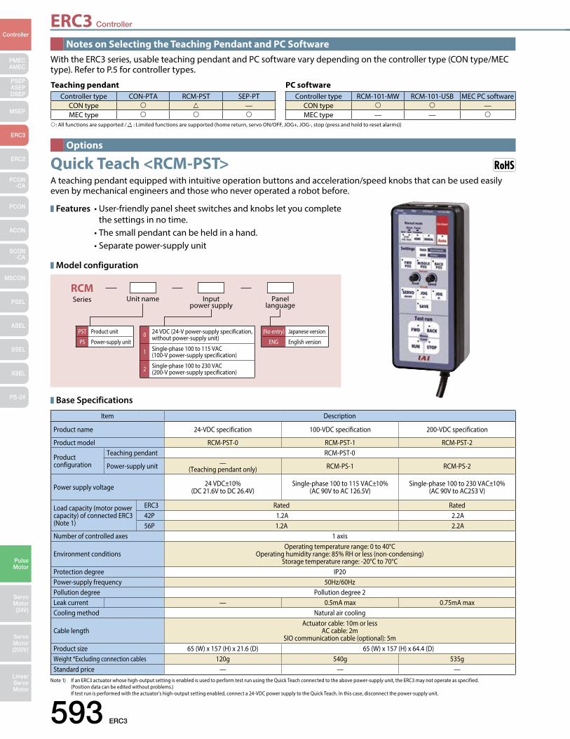
ERC3 Controller
593 ERC3
PMECAMEC
Controller
Pulse Motor
Servo Motor (24V)
Servo Motor (200V)
LinearServo Motor
PSEP ASEPDSEP
MSEP
ERC3
ERC2
PCON-CA
PCON
ACON
SCON-CA
MSCON
PSEL
ASEL
SSEL
XSEL
PS-24
Teaching pendantController type CON-PTA RCM-PST SEP-PT
CON type —MEC type
PC software Controller type RCM-101-MW RCM-101-USB MEC PC software
CON type —MEC type — —
RCMSeries Unit name Input
power supplyPanel
language
PST Product unit
PS Power-supply unit0 24 VDC (24-V power-supply specification,
without power-supply unit)
1 Single-phase 100 to 115 VAC (100-V power-supply specification)
2 Single-phase 100 to 230 VAC (200-V power-supply specification)
(No entry) Japanese version
ENG English version
Item Description
Product name 24-VDC specification 100-VDC specification 200-VDC specification
Product model RCM-PST-0 RCM-PST-1 RCM-PST-2
Productconfiguration
Teaching pendant RCM-PST-0
Power-supply unit —(Teaching pendant only) RCM-PS-1 RCM-PS-2
Power supply voltage 24 VDC±10%(DC 21.6V to DC 26.4V)
Single-phase 100 to 115 VAC±10%(AC 90V to AC 126.5V)
Single-phase 100 to 230 VAC±10%(AC 90V to AC253 V)
Load capacity (motor power capacity) of connected ERC3(Note 1)
ERC3 Rated Rated42P 1.2A 2.2A56P 1.2A 2.2A
Number of controlled axes 1 axis
Environment conditionsOperating temperature range: 0 to 40°C
Operating humidity range: 85% RH or less (non-condensing)Storage temperature range: -20°C to 70°C
Protection degree IP20Power-supply frequency 50Hz/60HzPollution degree Pollution degree 2Leak current — 0.5mA max 0.75mA maxCooling method Natural air cooling
Cable lengthActuator cable: 10m or less
AC cable: 2mSIO communication cable (optional): 5m
Product size 65 (W) x 157 (H) x 21.6 (D) 65 (W) x 157 (H) x 64.4 (D)Weight *Excluding connection cables 120g 540g 535gStandard price — — —
Notes on Selecting the Teaching Pendant and PC Software
Options
With the ERC3 series, usable teaching pendant and PC software vary depending on the controller type (CON type/MEC type). Refer to P.5 for controller types.
Features •User-friendlypanelsheetswitchesandknobsletyoucomplete the settings in no time. •Thesmallpendantcanbeheldinahand. •Separatepower-supplyunit
Model configuration
Base Specifications
: All functions are supported / : Limited functions are supported (home return, servo ON/OFF, JOG+, JOG-, stop (press and hold to reset alarms))
A teaching pendant equipped with intuitive operation buttons and acceleration/speed knobs that can be used easily even by mechanical engineers and those who never operated a robot before.
Quick Teach <RCM-PST>
Note 1) If an ERC3 actuator whose high-output setting is enabled is used to perform test run using the Quick Teach connected to the above power-supply unit, the ERC3 may not operate as specified. (Position data can be edited without problems.) If test run is performed with the actuator’s high-output setting enabled, connect a 24-VDC power supply to the Quick Teach. In this case, disconnect the power-supply unit.
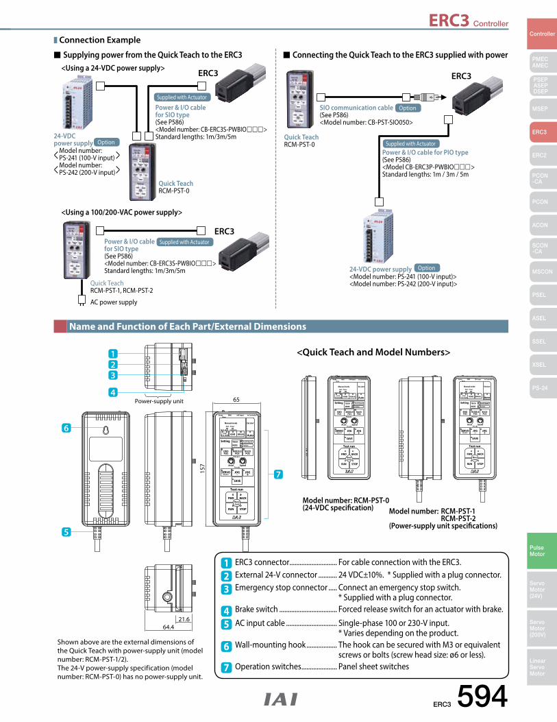
ERC3 Controller
ERC3 594
PMECAMEC
Controller
Pulse Motor
Servo Motor (24V)
Servo Motor (200V)
LinearServo Motor
PSEP ASEPDSEP
MSEP
ERC3
ERC2
PCON-CA
PCON
ACON
SCON-CA
MSCON
PSEL
ASEL
SSEL
XSEL
PS-24
Brake EMG
Manual mode
Auto
FWD BACK
RUN STOP
Test run
EWDPOS
MIDDLEPOS
BACKPOS
Setting
SERVOON/OFF
SAVE
JOG_ JOG+
HOME
TEACHMODE
MANUAL
Ext.start
Accel Speed
24V input
Alart Power
Accel & Speed
Position
STOPPOS NUM
to Controller
3pnt 2pnt Complete
Stop pos.
ManuCont
Pos.adj
Nom
Power-supply unit
21.6
65
157
64.4
Brake EMG
Manual mode
Auto
FWD BACK
RUN STOP
Test run
EWDPOS
MIDDLEPOS
BACKPOS
Setting
SERVOON/OFF
SAVE
JOG_ JOG+
HOME
TEACHMODE
MANUAL
Ext.start
Accel Speed
24V input
Alart Power
Accel & Speed
Position
STOPPOS NUM
to Controller
3pnt 2pnt Complete
Stop pos.
ManuCont
Pos.adj
NomBrake EMG
Manual mode
Auto
FWD BACK
RUN STOP
Test run
EWDPOS
MIDDLEPOS
BACKPOS
Setting
SERVOON/OFF
SAVE
JOG_ JOG+
HOME
TEACHMODE
MANUAL
Ext.start
Accel Speed
24V input
Alart Power
Accel & Speed
Position
STOPPOS NUM
to Controller
3pnt 2pnt Complete
Stop pos.
ManuCont
Pos.adj
Nom
1
6
5
23
4
7
Name and Function of Each Part/External Dimensions
Shown above are the external dimensions of the Quick Teach with power-supply unit (model number: RCM-PST-1/2). The 24-V power-supply specification (model number: RCM-PST-0) has no power-supply unit.
<Quick Teach and Model Numbers>
Model number: RCM-PST-0(24-VDC specification) Model number: RCM-PST-1
RCM-PST-2(Power-supply unit specifications)
ERC3 connector ............................ For cable connection with the ERC3. External 24-V connector ........... 24 VDC±10%. * Supplied with a plug connector. Emergency stop connector ..... Connect an emergency stop switch. * Supplied with a plug connector.Brake switch .................................. Forced release switch for an actuator with brake.
AC input cable .............................. Single-phase 100 or 230-V input. * Varies depending on the product. Wall-mounting hook .................. The hook can be secured with M3 or equivalent screws or bolts (screw head size: ø6 or less). Operation switches ..................... Panel sheet switches
123
4
6
7
5
Connection Example
ERC3
Quick Teach RCM-PST-0
<Using a 24-VDC power supply>Supplying power from the Quick Teach to the ERC3 Connecting the Quick Teach to the ERC3 supplied with power
24-VDC power supply
< Model number: PS-241 (100-V input) >< Model number: PS-242 (200-V input) >
Option
Power & I/O cable for SIO type(See P586)<Model number: CB-ERC3S-PWBIO>Standard lengths: 1m/3m/5m
Supplied with Actuator
ERC3
Quick Teach RCM-PST-0
SIO communication cable(See P586)<Model number: CB-PST-SIO050>
24-VDC power supply <Model number: PS-241 (100-V input)><Model number: PS-242 (200-V input)>
Option
Option
Power & I/O cable for PIO type(See P586)<Model CB-ERC3P-PWBIO>Standard lengths: 1m / 3m / 5m
Supplied with Actuator
ERC3
Quick Teach RCM-PST-1, RCM-PST-2
AC power supply
<Using a 100/200-VAC power supply>
Power & I/O cable for SIO type (See P586)<Model number: CB-ERC3S-PWBIO>Standard lengths: 1m/3m/5m
Supplied with Actuator
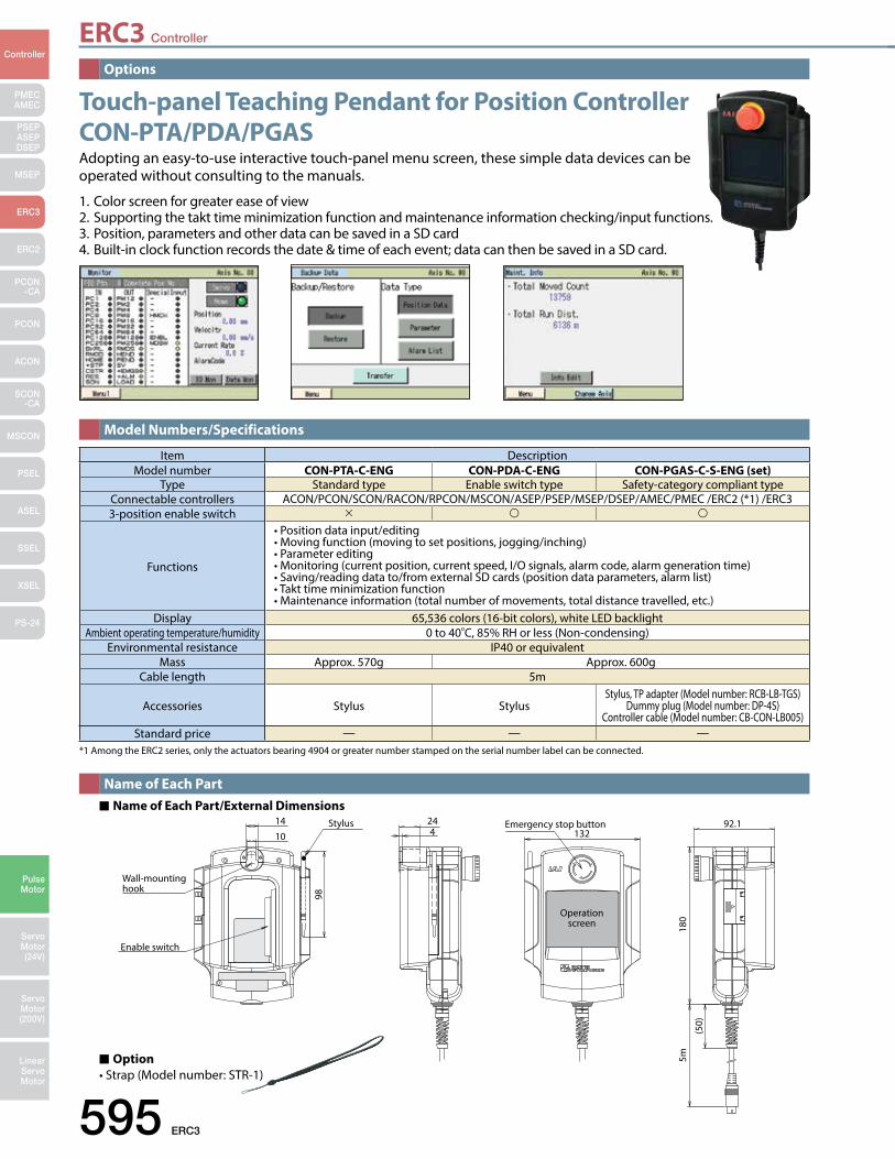
ERC3 Controller
595 ERC3
PMECAMEC
Controller
Pulse Motor
Servo Motor (24V)
Servo Motor (200V)
LinearServo Motor
PSEP ASEPDSEP
MSEP
ERC3
ERC2
PCON-CA
PCON
ACON
SCON-CA
MSCON
PSEL
ASEL
SSEL
XSEL
PS-24
Stylus
Wall-mounting hook
Enable switch
14 24
10 4
98
Emergency stop button
Operation screen
13292.1
180
5m
(50)
*1 Among the ERC2 series, only the actuators bearing 4904 or greater number stamped on the serial number label can be connected.
Touch-panel Teaching Pendant for Position Controller CON-PTA/PDA/PGAS Adopting an easy-to-use interactive touch-panel menu screen, these simple data devices can be operated without consulting to the manuals.
1. Color screen for greater ease of view2. Supporting the takt time minimization function and maintenance information checking/input functions.3. Position, parameters and other data can be saved in a SD card4. Built-in clock function records the date & time of each event; data can then be saved in a SD card.
Item DescriptionModel number CON-PTA-C-ENG CON-PDA-C-ENG CON-PGAS-C-S-ENG (set)
Type Standard type Enable switch type Safety-category compliant typeConnectable controllers ACON/PCON/SCON/RACON/RPCON/MSCON/ASEP/PSEP/MSEP/DSEP/AMEC/PMEC /ERC2 (*1) /ERC33-position enable switch
Functions
•Positiondatainput/editing•Movingfunction(movingtosetpositions,jogging/inching)•Parameterediting•Monitoring(currentposition,currentspeed,I/Osignals,alarmcode,alarmgenerationtime)•Saving/readingdatato/fromexternalSDcards(positiondataparameters,alarmlist)•Takttimeminimizationfunction•Maintenanceinformation(totalnumberofmovements,totaldistancetravelled,etc.)
Display 65,536 colors (16-bit colors), white LED backlightAmbient operating temperature/humidity 0 to 40C, 85% RH or less (Non-condensing)
Environmental resistance IP40 or equivalentMass Approx. 570g Approx. 600g
Cable length 5m
Accessories Stylus StylusStylus, TP adapter (Model number: RCB-LB-TGS)
Dummy plug (Model number: DP-4S)Controller cable (Model number: CB-CON-LB005)
Standard price — — —
Options
Model Numbers/Specifications
Name of Each PartName of Each Part/External Dimensions
Option•Strap(Modelnumber:STR-1)
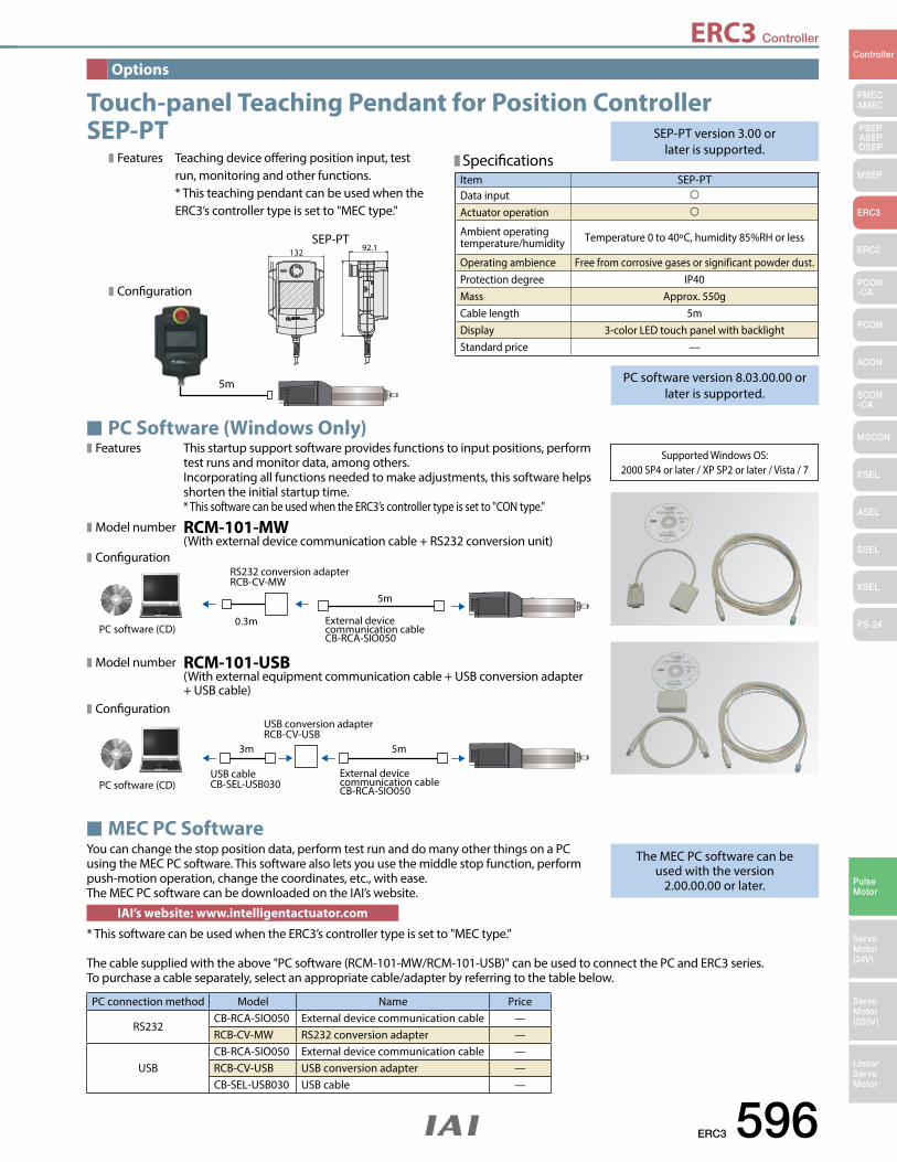
ERC3 Controller
ERC3 596
PMECAMEC
Controller
Pulse Motor
Servo Motor (24V)
Servo Motor (200V)
LinearServo Motor
PSEP ASEPDSEP
MSEP
ERC3
ERC2
PCON-CA
PCON
ACON
SCON-CA
MSCON
PSEL
ASEL
SSEL
XSEL
PS-24
Supported Windows OS: 2000 SP4 or later / XP SP2 or later / Vista / 7
RS232 conversion adapter RCB-CV-MW
External device communication cable CB-RCA-SIO050
0.3m
5m
PC software (CD)
External device communication cable CB-RCA-SIO050
USB conversion adapter RCB-CV-USB
USB cableCB-SEL-USB030
3m 5m
PC software (CD)
Features This startup support software provides functions to input positions, perform test runs and monitor data, among others. Incorporating all functions needed to make adjustments, this software helps shorten the initial startup time. * This software can be used when the ERC3’s controller type is set to "CON type."
Model number RCM-101-MW (With external device communication cable + RS232 conversion unit) Configuration
Model number RCM-101-USB (With external equipment communication cable + USB conversion adapter + USB cable) Configuration
Specifications
SEP-PT version 3.00 or later is supported.
PC software version 8.03.00.00 or later is supported.
The MEC PC software can be used with the version
2.00.00.00 or later.
Item SEP-PTData input
Actuator operation
Ambient operating temperature/humidity Temperature 0 to 40oC, humidity 85%RH or less
Operating ambience Free from corrosive gases or significant powder dust.Protection degree IP40Mass Approx. 550gCable length 5mDisplay 3-color LED touch panel with backlightStandard price —
PC connection method Model Name Price
RS232CB-RCA-SIO050 External device communication cable —RCB-CV-MW RS232 conversion adapter —
USBCB-RCA-SIO050 External device communication cable —RCB-CV-USB USB conversion adapter —CB-SEL-USB030 USB cable —
Options
Touch-panel Teaching Pendant for Position Controller SEP-PT
PC Software (Windows Only)
MEC PC SoftwareYou can change the stop position data, perform test run and do many other things on a PC using the MEC PC software. This software also lets you use the middle stop function, perform push-motion operation, change the coordinates, etc., with ease. The MEC PC software can be downloaded on the IAI’s website.
* This software can be used when the ERC3’s controller type is set to "MEC type."
IAI’s website: www.intelligentactuator.com
The cable supplied with the above "PC software (RCM-101-MW/RCM-101-USB)" can be used to connect the PC and ERC3 series. To purchase a cable separately, select an appropriate cable/adapter by referring to the table below.
Features Teaching device offering position input, test run, monitoring and other functions. * This teaching pendant can be used when the ERC3’s controller type is set to "MEC type."
SEP-PT132 92.1
Configuration
5m
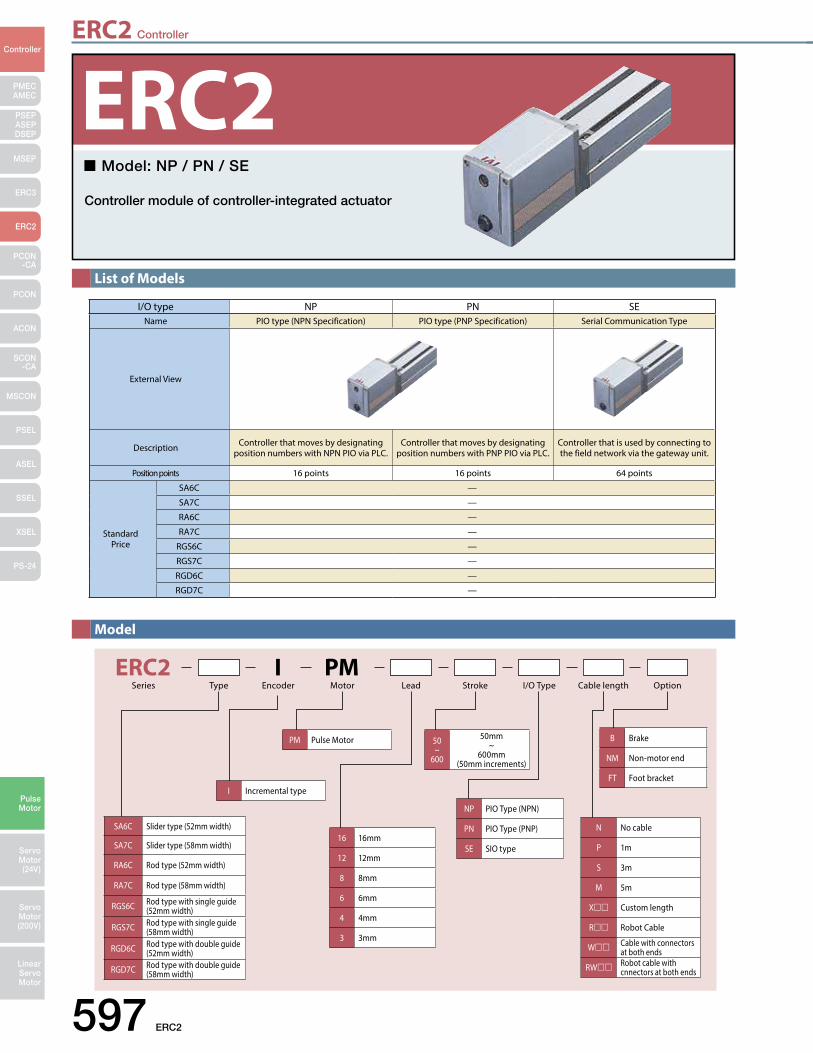
ERC2 Controller
597 ERC2
PMECAMEC
Controller
Pulse Motor
Servo Motor (24V)
Servo Motor (200V)
LinearServo Motor
PSEP ASEPDSEP
MSEP
ERC3
ERC2
PCON-CA
PCON
ACON
SCON-CA
MSCON
PSEL
ASEL
SSEL
XSEL
PS-24
List of Models
Model
ERC2 I PMTypeSeries Encoder Motor Lead Stroke I/O Type Cable length Option
I Incremental type
PM Pulse Motor 50 ~
600
50mm ~
600mm(50mm increments)
NP PIO Type (NPN)
PN PIO Type (PNP)
SE SIO type
B Brake
NM Non-motor end
FT Foot bracket
16 16mm
12 12mm
8 8mm
6 6mm
4 4mm
3 3mm
N No cable
P 1m
S 3m
M 5m
X Custom length
R Robot Cable
W Cable with connectors at both ends
RW Robot cable with cnnectors at both ends
SA6C Slider type (52mm width)
SA7C Slider type (58mm width)
RA6C Rod type (52mm width)
RA7C Rod type (58mm width)
RGS6C Rod type with single guide (52mm width)
RGS7C Rod type with single guide (58mm width)
RGD6C Rod type with double guide (52mm width)
RGD7C Rod type with double guide (58mm width)
I/O type NP PN SEName PIO type (NPN Specification) PIO type (PNP Specification) Serial Communication Type
External View
Description Controller that moves by designating position numbers with NPN PIO via PLC.
Controller that moves by designatingposition numbers with PNP PIO via PLC.
Controller that is used by connecting to the field network via the gateway unit.
Position points 16 points 16 points 64 points
Standard Price
SA6C —
SA7C —
RA6C —
RA7C —
RGS6C —
RGS7C —
RGD6C —
RGD7C —
Model: NP / PN / SE
Controller module of controller-integrated actuator
ERC2
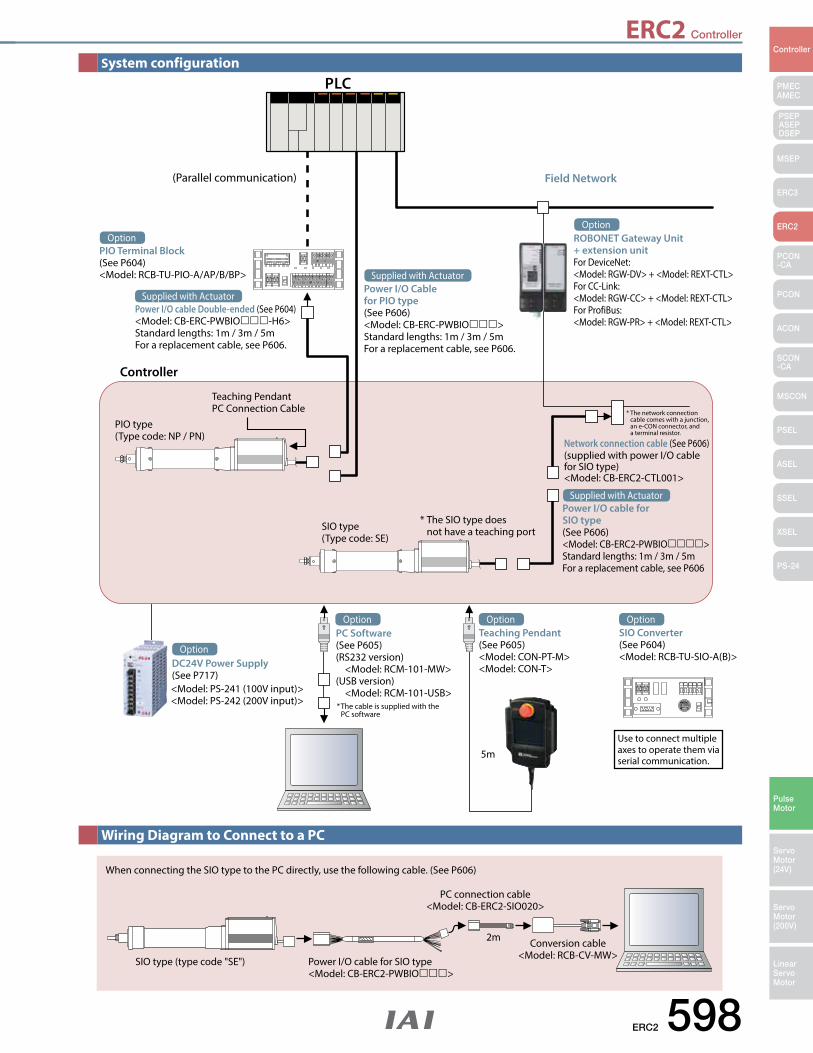
ERC2 Controller
ERC2 598
PMECAMEC
Controller
Pulse Motor
Servo Motor (24V)
Servo Motor (200V)
LinearServo Motor
PSEP ASEPDSEP
MSEP
ERC3
ERC2
PCON-CA
PCON
ACON
SCON-CA
MSCON
PSEL
ASEL
SSEL
XSEL
PS-24
System configuration
Wiring Diagram to Connect to a PC
(Parallel communication) Field Network
Controller
Teaching PendantPC Connection Cable
PIO type(Type code: NP / PN)
SIO type(Type code: SE)
* The SIO type does not have a teaching port
* The network connection cable comes with a junction, an e-CON connector, and a terminal resistor.
Network connection cable (See P606)(supplied with power I/O cable for SIO type)<Model: CB-ERC2-CTL001>
* The cable is supplied with the PC software
Use to connect multiple axes to operate them via serial communication.
PLC
Power I/O cable Double-ended (See P604)<Model: CB-ERC-PWBIO-H6>Standard lengths: 1m / 3m / 5mFor a replacement cable, see P606.
Supplied with ActuatorPower I/O Cable for PIO type(See P606)<Model: CB-ERC-PWBIO>Standard lengths: 1m / 3m / 5mFor a replacement cable, see P606.
Supplied with Actuator
Power I/O cable for SIO type(See P606)<Model: CB-ERC2-PWBIO>Standard lengths: 1m / 3m / 5mFor a replacement cable, see P606
Supplied with Actuator
PIO Terminal Block(See P604)<Model: RCB-TU-PIO-A/AP/B/BP>
Option ROBONET Gateway Unit+ extension unitFor DeviceNet:<Model: RGW-DV> + <Model: REXT-CTL>For CC-Link:<Model: RGW-CC> + <Model: REXT-CTL>For ProfiBus:<Model: RGW-PR> + <Model: REXT-CTL>
Option
<Model: PS-241 (100V input)><Model: PS-242 (200V input)>
DC24V Power Supply(See P717)
Option
PC Software(See P605)(RS232 version) <Model: RCM-101-MW>(USB version) <Model: RCM-101-USB>
OptionTeaching Pendant(See P605)<Model: CON-PT-M><Model: CON-T>
OptionSIO Converter(See P604)<Model: RCB-TU-SIO-A(B)>
Option
When connecting the SIO type to the PC directly, use the following cable. (See P606)
SIO type (type code "SE") Power I/O cable for SIO type <Model: CB-ERC2-PWBIO>
PC connection cable <Model: CB-ERC2-SIO020>
Conversion cable <Model: RCB-CV-MW>
2m
5m
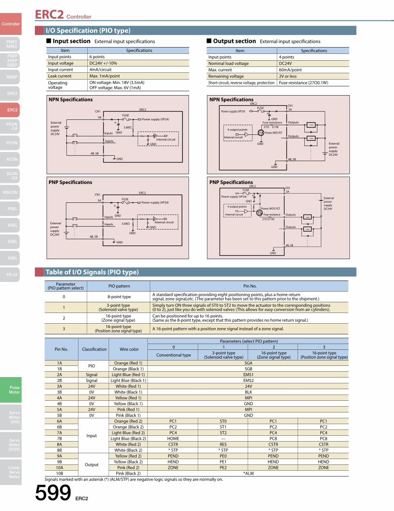
ERC2 Controller
599 ERC2
PMECAMEC
Controller
Pulse Motor
Servo Motor (24V)
Servo Motor (200V)
LinearServo Motor
PSEP ASEPDSEP
MSEP
ERC3
ERC2
PCON-CA
PCON
ACON
SCON-CA
MSCON
PSEL
ASEL
SSEL
XSEL
PS-24
I/O Specification (PIO type)
Table of I/O Signals (PIO type)
External power supplyDC24V
Power supply (VP24)
Inputs
CN1
3A
4B, 5B
Inputs
5.6KΩ
FUSE
ERC2
GND
GND
GNDInternal circuit
+
NPN Specifications
External power supply DC24V
Power supply (VP24)
Outputs
Outputs
4 output points
Load
Load
27Ω 0.1WFuse resistance
ERC2CN13A
4B, 5B
FUSE
GND
GND
GND
Power MOS FET Internal circuit
+
NPN Specifications
External power supply DC24V
Power supply (VP24)
Inputs
CN1
3A
4B, 5B
Inputs 5.6KΩ
FUSE
ERC2
GND
GND
GND
GND
Internal circuit
PNP Specifications
External power supply DC24V
Power supply (VP24)
Outputs
Outputs
4 output points
Load
Load 27Ω 0.1W
Fuse resistance
ERC2CN13A
4B, 5B
FUSE
GND
GND
Power MOS FET
Internal circuit
+
PNP Specifications
Item SpecificationsInput points 6 pointsInput voltage DC24V +/-10%Input current 4mA/circuitLeak current Max. 1mA/point
Operating voltage
ON voltage: Min. 18V (3.5mA)OFF voltage: Max. 6V (1mA)
Input section External input specifications
Item SpecificationsInput points 4 pointsNominal load voltage DC24VMax. current 60mA/pointRemaining voltage 2V or lessShort-circuit, reverse voltage, protection Fuse resistance (27Ω0.1W)
Output section External input specifications
Parameter (PIO pattern select) PIO pattern Pin No.
0 8-point type A standard specification providing eight positioning points, plus a home return signal, zone signal,etc. (The parameter has been set to this pattern prior to the shipment.)
1 3-point type(Solenoid valve type)
Simply turn ON three signals of ST0 to ST2 to move the actuator to the corresponding positions (0 to 2), just like you do with solenoid valves (This allows for easy conversion from air cylinders).
2 16-point type(Zone signal type)
Can be positioned for up to 16 points. (Same as the 8-point type, except that this pattern provides no home return signal.)
3 16-point type(Position zone signal type) A 16-point pattern with a position zone signal instead of a zone signal.
Pin No. Classification Wire color
Parameters (select PIO pattern)0 1 2 3
Conventional type 3-point type (Solenoid valve type)
16-point type (Zone signal type)
16-point type (Position zone signal type)
1APIO
Orange (Red 1) SGA1B Orange (Black 1) SGB2A Signal Light Blue (Red 1) EMS12B Signal Light Blue (Black 1) EMS23A 24V White (Red 1) 24V3B 0V White (Black 1) BLK4A 24V Yellow (Red 1) MPI4B 0V Yellow (Black 1) GND5A 24V Pink (Red 1) MPI5B 0V Pink (Black 1) GND6A
Input
Orange (Red 2) PC1 ST0 PC1 PC16B Orange (Black 2) PC2 ST1 PC2 PC27A Light Blue (Red 2) PC4 ST2 PC4 PC47B Light Blue (Black 2) HOME — PC8 PC88A White (Red 2) CSTR RES CSTR CSTR8B White (Black 2) * STP * STP * STP * STP9A
Output
Yellow (Red 2) PEND PE0 PEND PEND9B Yellow (Black 2) HEND PE1 HEND HEND
10A Pink (Red 2) ZONE PE2 ZONE ZONE10B Pink (Black 2) *ALM
Signals marked with an asterisk (*) (ALM/STP) are negative logic signals so they are normally on.
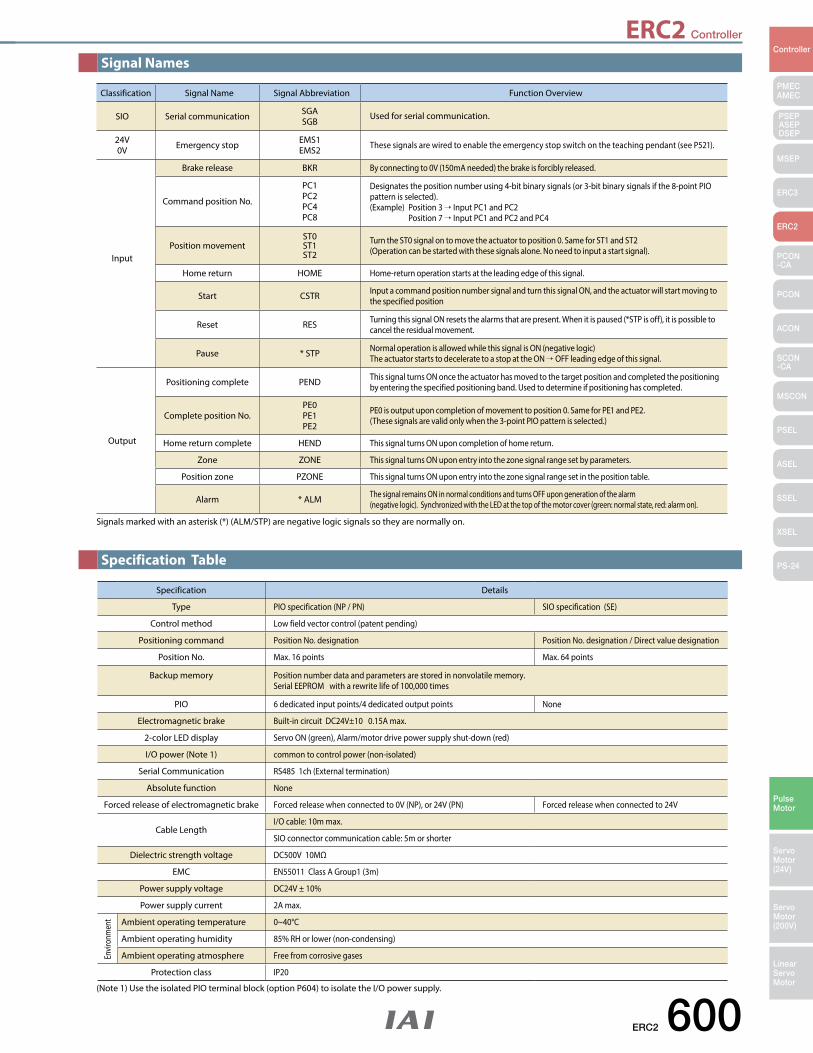
ERC2 Controller
ERC2 600
PMECAMEC
Controller
Pulse Motor
Servo Motor (24V)
Servo Motor (200V)
LinearServo Motor
PSEP ASEPDSEP
MSEP
ERC3
ERC2
PCON-CA
PCON
ACON
SCON-CA
MSCON
PSEL
ASEL
SSEL
XSEL
PS-24
Signal Names
Specification Table
Classification Signal Name Signal Abbreviation Function Overview
SIO Serial communication SGASGB
Used for serial communication.
24V0V Emergency stop EMS1
EMS2 These signals are wired to enable the emergency stop switch on the teaching pendant (see P521).
Input
Brake release BKR By connecting to 0V (150mA needed) the brake is forcibly released.
Command position No.
PC1PC2PC4PC8
Designates the position number using 4-bit binary signals (or 3-bit binary signals if the 8-point PIO pattern is selected).(Example) Position 3 → Input PC1 and PC2 Position 7 → Input PC1 and PC2 and PC4
Position movementST0ST1ST2
Turn the ST0 signal on to move the actuator to position 0. Same for ST1 and ST2 (Operation can be started with these signals alone. No need to input a start signal).
Home return HOME Home-return operation starts at the leading edge of this signal.
Start CSTR Input a command position number signal and turn this signal ON, and the actuator will start moving to the specified position
Reset RES Turning this signal ON resets the alarms that are present. When it is paused (*STP is off), it is possible to cancel the residual movement.
Pause * STP Normal operation is allowed while this signal is ON (negative logic) The actuator starts to decelerate to a stop at the ON →OFF leading edge of this signal.
Output
Positioning complete PEND This signal turns ON once the actuator has moved to the target position and completed the positioning by entering the specified positioning band. Used to determine if positioning has completed.
Complete position No.PE0PE1PE2
PE0 is output upon completion of movement to position 0. Same for PE1 and PE2. (These signals are valid only when the 3-point PIO pattern is selected.)
Home return complete HEND This signal turns ON upon completion of home return.
Zone ZONE This signal turns ON upon entry into the zone signal range set by parameters.
Position zone PZONE This signal turns ON upon entry into the zone signal range set in the position table.
Alarm * ALM The signal remains ON in normal conditions and turns OFF upon generation of the alarm (negative logic). Synchronized with the LED at the top of the motor cover (green: normal state, red: alarm on).
Signals marked with an asterisk (*) (ALM/STP) are negative logic signals so they are normally on.
Specification Details
Type PIO specification (NP / PN) SIO specification (SE)
Control method Low field vector control (patent pending)
Positioning command Position No. designation Position No. designation / Direct value designation
Position No. Max. 16 points Max. 64 points
Backup memory Position number data and parameters are stored in nonvolatile memory. Serial EEPROM with a rewrite life of 100,000 times
PIO 6 dedicated input points/4 dedicated output points None
Electromagnetic brake Built-in circuit DC24V±10 0.15A max.
2-color LED display Servo ON (green), Alarm/motor drive power supply shut-down (red)
I/O power (Note 1) common to control power (non-isolated)
Serial Communication RS485 1ch (External termination)
Absolute function None
Forced release of electromagnetic brake Forced release when connected to 0V (NP), or 24V (PN) Forced release when connected to 24V
Cable LengthI/O cable: 10m max.
SIO connector communication cable: 5m or shorter
Dielectric strength voltage DC500V 10MΩ
EMC EN55011 Class A Group1 (3m)
Power supply voltage DC24V ± 10%
Power supply current 2A max.
Ambient operating temperature 0~40°C
Ambient operating humidity 85% RH or lower (non-condensing)
Ambient operating atmosphere Free from corrosive gases
Protection class IP20
Envir
onm
ent
(Note 1) Use the isolated PIO terminal block (option P604) to isolate the I/O power supply.
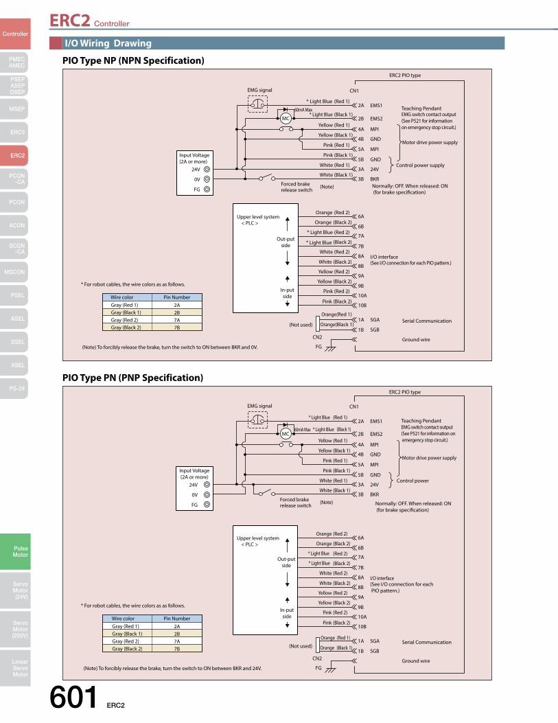
ERC2 Controller
601 ERC2
PMECAMEC
Controller
Pulse Motor
Servo Motor (24V)
Servo Motor (200V)
LinearServo Motor
PSEP ASEPDSEP
MSEP
ERC3
ERC2
PCON-CA
PCON
ACON
SCON-CA
MSCON
PSEL
ASEL
SSEL
XSEL
PS-24
I/O Wiring Drawing
24V
0V
FG
Input Voltage (2A or more)
SGA
SGB
Control power supply
Normally: OFF. When released: ON (for brake specication)
Motor drive power supply
I/O interface (See I/O connection for each PIO pattern.)
Serial Communication
6A
6B
EMS12A
EMS22B
MPI4A
GND4B
MPI5A
GND5B
24V3A
BKR3B
7A
7B
8A
8B
9A
9B
10A
10B
1A
1B
MC
EMG signal
Forced brake release switch
(Note)
60mA Max
Upper level system < PLC >
Teaching Pendant EMG switch contact output(See P521 for information on emergency stop circuit.)
ERC2 PIO type
CN1
CN2
FG
(Red 1) Yellow
(Black 1) Yellow
(Red 1) * Light Blue
(Black 1) * Light Blue
(Red 1) Pink
(Black 1) Pink
(Red 1) White
(Black 1) White
(Red 2) Orange
(Black 2) Orange
(Red 2) * Light Blue
* Light Blue (Black 2)
(Red 2) White
(Black 2) White
(Red 2) Yellow
(Black 2) Yellow
(Red 2) Pink
(Black 2) Pink
(Red 1) Orange
(Black 1) Orange (Not used)
Ground wire (Note) To forcibly release the brake, turn the switch to ON between BKR and 0V.
* For robot cables, the wire colors as as follows.
Wire colorGray (Red 1)Gray (Black 1)Gray (Red 2)Gray (Black 2)
Pin Number2A2B7A7B
Out-put side
In-put side
PIO Type NP (NPN Specification)
PIO Type PN (PNP Specification)
* For robot cables, the wire colors as as follows.
Wire colorGray (Red 1)Gray (Black 1)Gray (Red 2)Gray (Black 2)
Pin Number2A2B7A7B
24V
0V
FG
Input Voltage (2A or more)
SGA
SGB
Control power
Normally: OFF. When released: ON (for brake specication)
Motor drive power supply
I/O interface (See I/O connection for each PIO pattern.)
Serial Communication
6A
6B
EMS12A
EMS22B
MPI4A
GND4B
MPI5A
GND5B
24V3A
BKR3B
7A
7B
8A
8B
9A
9B
10A
10B
1A
1B
MC
EMG signal
60mA Max
Upper level system < PLC >
Teaching Pendant
ERC2 PIO type
CN1
CN2
FG
(Red 1) Yellow
(Black 1) Yellow
(Red 1) * Light Blue
(Black 1) * Light Blue
(Red 1) Pink
(Black 1) Pink
(Red 1) White
(Black 1) White
(Red 2) Orange
(Black 2) Orange
(Red 2) * Light Blue
(Black 2) * Light Blue
(Red 2) White
(Black 2) White
(Red 2) Yellow
(Black 2) Yellow
(Red 2) Pink
(Black 2) Pink
(Red 1) Orange
(Black 1) Orange (Not used)
Ground wire
Forced brake release switch
(Note)
EMG switch contact output (See P521 for information on emergency stop circuit.)
(Note) To forcibly release the brake, turn the switch to ON between BKR and 24V.
Out-put side
In-put side
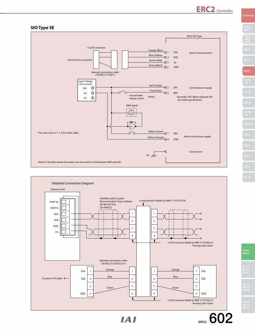
ERC2 Controller
ERC2 602
PMECAMEC
Controller
Pulse Motor
Servo Motor (24V)
Servo Motor (200V)
LinearServo Motor
PSEP ASEPDSEP
MSEP
ERC3
ERC2
PCON-CA
PCON
ACON
SCON-CA
MSCON
PSEL
ASEL
SSEL
XSEL
PS-24
* The wire color in "( )" is for robot cable.
24V
0V
FG
Input Voltage (2A or more)
SGA
SGB
5V
GND
Control power supply
Motor drive power supply
Serial Communication
MPI7
GND8
24V5
BKR6
1
2
3
4
MC
EMG signal
Forced brake release switch
(Note)
ERC2 SIO Type
e-CON connector
connected to a junction
Network connection cable<CB-ERC2-CTL001>
FGGround wire
Orange (Blue)
Brown (Red)
Blue (Yellow)
Green (Black)
Red (Purple)
Gray (Gray)
Yellow (Green)
Yellow (Orange)
(Note) To forcibly release the brake, turn the switch to ON between BKR and 24V.
Normally: OFF. When released: ON (for brake specication)
SIO Type SE
PORT IN
PORT N
SDA
SDB
GND
FG
Gateway Unit
Shielded cable (2 pairs)Recommended: Taiyo CabletecHK-SB/20276×L2P×AWG22
4-way junction (Made by AMP: 5-1473574-4)
e-CON connector (Made by AMP: 4-1473562-4)Housing color: Green
e-CON connector (Made by AMP: 3-1473562-4)Housing color: Green
Orange
Blue
Green
Orange
Network connection cableCB-ERC2-CTL001(0.1m)
To power I/O cableBlue
Green
Detailed Connection Diagram
1
2
3
4
1
2
3
4
1
2
3
4
1
2
3
4
1
2
3
4
SGA
SGB
GND
SGA
SGB
GND
1
2
3
4
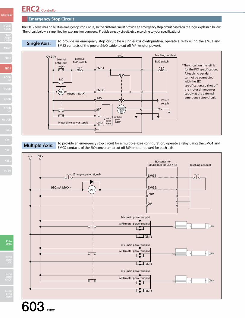
ERC2 Controller
603 ERC2
PMECAMEC
Controller
Pulse Motor
Servo Motor (24V)
Servo Motor (200V)
LinearServo Motor
PSEP ASEPDSEP
MSEP
ERC3
ERC2
PCON-CA
PCON
ACON
SCON-CA
MSCON
PSEL
ASEL
SSEL
XSEL
PS-24(Emergency stop signal)
SIO converterModel: RCB-TU-SIO-A (B) Teaching pendant
24V (main power supply)
MPI (motor power supply)
24V (main power supply)
24V (main power supply)
MPI (motor power supply)
MPI (motor power supply)
Emergency Stop Circuit
The ERC2 series has no built-in emergency stop circuit, so the customer must provide an emergency stop circuit based on the logic explained below. (The circuit below is simplified for explanation purposes. Provide a ready circuit, etc., according to your specification.)
To provide an emergency stop circuit for a single-axis configuration, operate a relay using the EMS1 and EMS2 contacts of the power & I/O cable to cut off MPI (motor power). Single Axis:
To provide an emergency stop circuit for a multiple-axes configuration, operate a relay using the EMG1 and EMG2 contacts of the SIO converter to cut off MPI (motor power) for each axis.Multiple Axis:
External EMO reset
switch
External EMG switch
ERC2 Teaching pendant
Power supply
EMG switch
Motor drive power supply
Motor power supply
Controller power supply
Connection detection
relay
* The circuit on the left is for the PIO specification.A teaching pendant cannot be connected with the SIO specification, so shut off the motor drive power supply at the external emergency stop circuit.
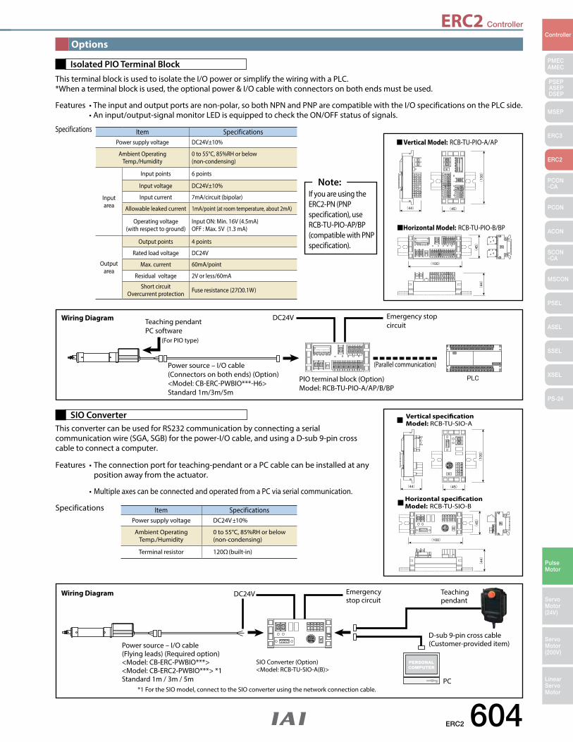
ERC2 Controller
ERC2 604
PMECAMEC
Controller
Pulse Motor
Servo Motor (24V)
Servo Motor (200V)
LinearServo Motor
PSEP ASEPDSEP
MSEP
ERC3
ERC2
PCON-CA
PCON
ACON
SCON-CA
MSCON
PSEL
ASEL
SSEL
XSEL
PS-24
Options
This terminal block is used to isolate the I/O power or simplify the wiring with a PLC. *When a terminal block is used, the optional power & I/O cable with connectors on both ends must be used.
Features•Theinputandoutputportsarenon-polar,sobothNPNandPNParecompatiblewiththeI/OspecificationsonthePLCside. •Aninput/output-signalmonitorLEDisequippedtochecktheON/OFFstatusofsignals.
Specifications
Isolated PIO Terminal Block
Vertical Model: RCB-TU-PIO-A/AP
Horizontal Model: RCB-TU-PIO-B/BP
Vertical specicationModel: RCB-TU-SIO-A
Horizontal specicationModel: RCB-TU-SIO-B
(For PIO type)
Teaching pendantPC software
Power source – I/O cable(Connectors on both ends) (Option)<Model: CB-ERC-PWBIO***-H6>Standard 1m/3m/5m
PIO terminal block (Option)Model: RCB-TU-PIO-A/AP/B/BP
Emergency stop circuit
DC24V
(Parallel communication)
Wiring Diagram
If you are using the ERC2-PN (PNP specification), use RCB-TU-PIO-AP/BP (compatible with PNP specification).
Note:
Item SpecificationsPower supply voltage DC24V±10%
Ambient Operating Temp./Humidity
0 to 55°C, 85%RH or below(non-condensing)
Input area
Input points 6 points
Input voltage DC24V±10%
Input current 7mA/circuit (bipolar)
Allowable leaked current 1mA/point (at room temperature, about 2mA)
Operating voltage(with respect to ground)
Input ON: Min. 16V (4.5mA) OFF : Max. 5V (1.3 mA)
Output area
Output points 4 points
Rated load voltage DC24V
Max. current 60mA/point
Residual voltage 2V or less/60mA
Short circuitOvercurrent protection Fuse resistance (27Ω0.1W)
This converter can be used for RS232 communication by connecting a serial communication wire (SGA, SGB) for the power-I/O cable, and using a D-sub 9-pin cross cable to connect a computer.
Features •Theconnectionportforteaching-pendantoraPCcablecanbeinstalledatany position away from the actuator.
•Multiple axes can be connected and operated from a PC via serial communication.
Specifications
SIO Converter
Item SpecificationsPower supply voltage DC24V ±10%
Ambient Operating Temp./Humidity
0 to 55°C, 85%RH or below(non-condensing)
Terminal resistor 120Ω (built-in)
*1 For the SIO model, connect to the SIO converter using the network connection cable.
Power source – I/O cable(Flying leads) (Required option)<Model: CB-ERC-PWBIO***><Model: CB-ERC2-PWBIO***> *1Standard 1m / 3m / 5m
Emergency stop circuit
DC24V Teaching pendant
D-sub 9-pin cross cable(Customer-provided item)
PC
Wiring Diagram
SIO Converter (Option)<Model: RCB-TU-SIO-A(B)>
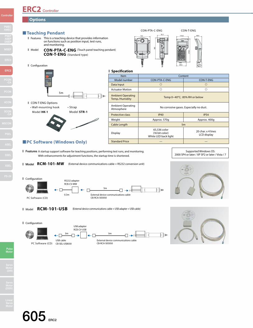
605 ERC2
PMECAMEC
Controller
Pulse Motor
Servo Motor (24V)
Servo Motor (200V)
LinearServo Motor
PSEP ASEPDSEP
MSEP
ERC3
ERC2
PCON-CA
PCON
ACON
SCON-CA
MSCON
PSEL
ASEL
SSEL
XSEL
PS-24
ERC2 Controller
Options
PC Software (Windows Only)
A startup support software for teaching positions, performing test runs, and monitoring. With enhancements for adjustment functions, the startup time is shortened.
Features
Model
Conguration
RCM-101-MW (External device communications cable + RS232 conversion unit)
0.3m
5m
External device communications cableCB-RCA-SIO050PC Software (CD)
RS232 adapterRCB-CV-MW
Model
Conguration
RCM-101-USB (External device communications cable + USB adapter + USB cable)
5m3m
PC Software (CD)External device communications cableCB-RCA-SIO050
USB cableCB-SEL-USB030
USB adapterRCB-CV-USB
Teaching PendantThis is a teaching device that provides information on functions such as position input, test runs, and monitoring.
CON-PTA-C-ENG (Touch panel teaching pendant)
CON-T-ENG (Standard type)
Features
Model
Conguration
5m
CON-T-ENG Options• Wall-mounting hook
Model HK-1
• Strap
Model STR-1
CON-T-ENGCON-PTA-C-ENG
46.939.0
66.6110.0
218.
3
89.6
13292.1
180
Item ContentModel number CON-PTA-C-ENG CON-T-ENG
Data Input
Actuator Motion
Ambient Operating Temp./Humidity Temp 0~40°C; 85% RH or below
Ambient Operating Atmosphere No corrosive gases. Especially no dust.
Protective class IP40 IP54
Weight Approx. 570g Approx. 400g
Cable Length 5m
Display65,536 color(16 bit color)
White LED back light
20 char. x 4 lines LCD display
Standard Price — —
Specification
Supported Windows OS: 2000 SP4 or later / XP SP2 or later / Vista / 7
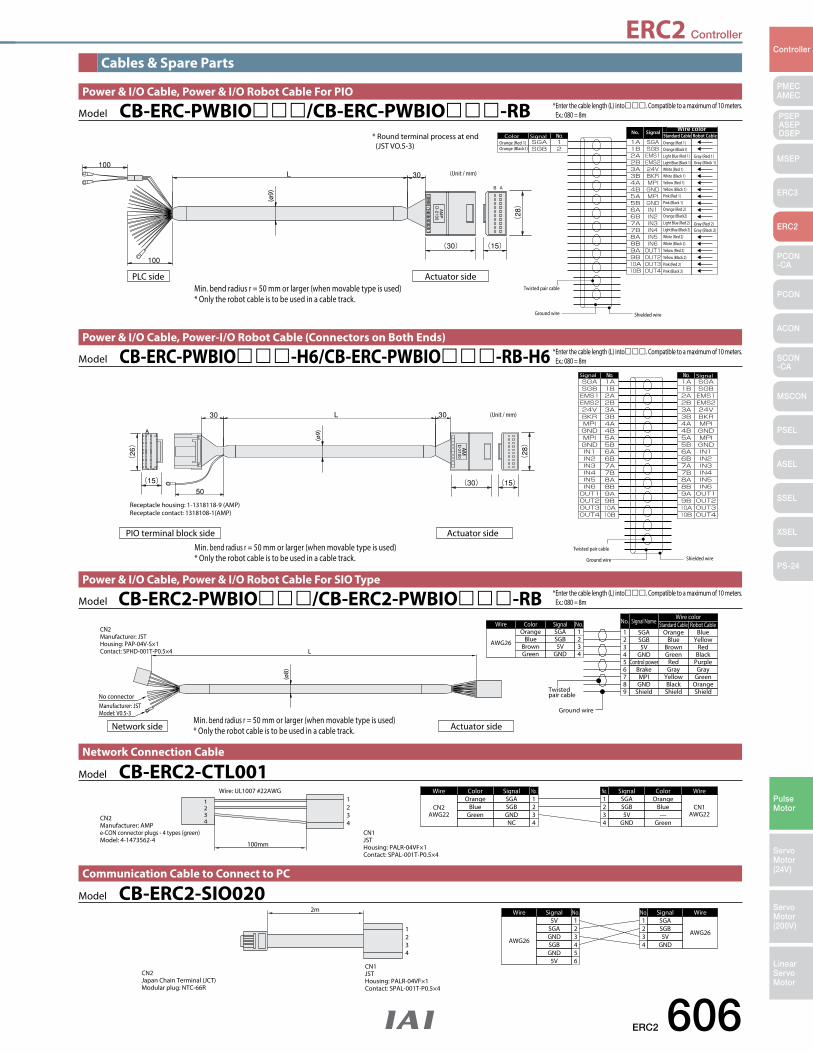
ERC2 606
PMECAMEC
Controller
Pulse Motor
Servo Motor (24V)
Servo Motor (200V)
LinearServo Motor
PSEP ASEPDSEP
MSEP
ERC3
ERC2
PCON-CA
PCON
ACON
SCON-CA
MSCON
PSEL
ASEL
SSEL
XSEL
PS-24
ERC2 Controller
Cables & Spare Parts
1234
1234
Wire: UL1007 #22AWG
100mm
CN2Manufacturer: AMPe-CON connector plugs - 4 types (green)Model: 4-1473562-4
CN1JSTHousing: PALR-04VF×1Contact: SPAL-001T-P0.5×4
ColorOrange
BlueGreen
Wire
CN2AWG22
Signal No.1234
SGASGBGNDNC
ColorOrange
Blue—
Green
Wire
CN1AWG22
SignalNo.1234
SGASGB5V
GND
Model CB-ERC2-CTL001Network Connection Cable
Wire
AWG26
Signal No.1234
5VSGAGNDSGB
5GND65V
Wire
AWG26
SignalNo.1234
SGASGB5V
GND
1234
2m
CN2Japan Chain Terminal (JCT)Modular plug: NTC-66R
CN1JSTHousing: PALR-04VF×1Contact: SPAL-001T-P0.5×4
Model CB-ERC2-SIO020Communication Cable to Connect to PC
* Enter the cable length (L) into. Compatible to a maximum of 10 meters. Ex.: 080 = 8m
Manufacturer: JSTModel: V0.5-3
No connector
L
CN2Manufacturer: JSTHousing: PAP-04V-S×1Contact: SPHD-001T-P0.5×4
Twistedpair cable
Ground wire
ColorOrange
BlueBrownGreen
Wire
AWG26
Signal No.1234
SGASGB5V
GND
Signal Name
OrangeSGABlue
BrownGreen
SGB5V
GND
Robot CableStandard CableWire color
No.
1234
BlueYellow
RedBlack
RedControl power5 PurpleGrayBrake6 Gray
YellowMPI7 GreenBlackGND8 OrangeShieldShield9 Shield
(ø8)
Network side Actuator side
Model CB-ERC2-PWBIO/CB-ERC2-PWBIO-RBPower & I/O Cable, Power & I/O Robot Cable For SIO Type
Min. bend radius r = 50 mm or larger (when movable type is used)* Only the robot cable is to be used in a cable track.
Receptacle housing: 1-1318118-9 (AMP)Receptacle contact: 1318108-1(AMP)
(Unit / mm)
Twisted pair cable
Ground wire Shielded wire
Signal Signal
(ø9)
PIO terminal block side Actuator side
* Enter the cable length (L) into. Compatible to a maximum of 10 meters. Ex.: 080 = 8mModel CB-ERC-PWBIO-H6/CB-ERC-PWBIO-RB-H6
Power & I/O Cable, Power-I/O Robot Cable (Connectors on Both Ends)
Min. bend radius r = 50 mm or larger (when movable type is used)* Only the robot cable is to be used in a cable track.
Standard Cable Robot CableWire color
(ø9)
PLC side Actuator side
Color SignalSignalNo.
Orange (Red 1)Orange (Black1)
Orange (Red 1)Orange (Black1)Light Blue (Red 1)Light Blue (Black 1)White (Red 1)White (Black 1)Yellow (Red 1)Yellow (Black 1)Pink (Red 1)Pink (Black 1)Orange (Red 2)Orange (Black2)Light Blue (Red 2)Light Blue (Black 2)White (Red 2)White (Black 2)Yellow (Red 2)Yellow (Black 2)Pink (Red 2)Pink (Black 2)
Gray (Black 2)Gray (Red 2)
Gray (Black 1)Gray (Red 1)
Twisted pair cable
Ground wire Shielded wire
(Unit / mm)
* Round terminal process at end (JST VO.5-3)
Model CB-ERC-PWBIO/CB-ERC-PWBIO-RBPower & I/O Cable, Power & I/O Robot Cable For PIO
* Enter the cable length (L) into. Compatible to a maximum of 10 meters. Ex.: 080 = 8m
Min. bend radius r = 50 mm or larger (when movable type is used)* Only the robot cable is to be used in a cable track.
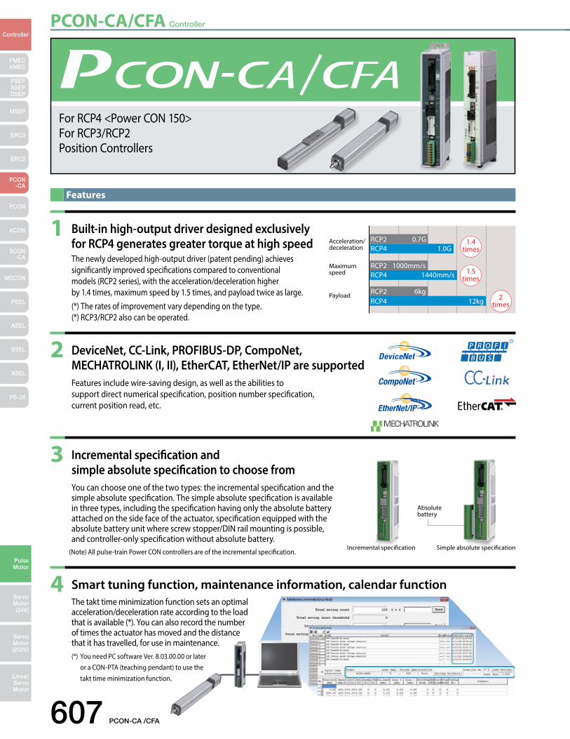
PCON-CA/CFA Controller
607 PCON-CA /CFA
PMECAMEC
Controller
Pulse Motor
Servo Motor (24V)
Servo Motor (200V)
LinearServo Motor
PSEP ASEPDSEP
MSEP
ERC3
ERC2
PCON-CA
PCON
ACON
SCON-CA
MSCON
PSEL
ASEL
SSEL
XSEL
PS-24
Features
Acceleration/ deceleration
1.4 times
1.5 times
2 times
RCP2 0.7GRCP4 1.0G
RCP2 1000mm/sRCP4 1440mm/s
RCP2 6kgRCP4 12kg
Payload
Maximum speed
Incremental specification Simple absolute specification
Absolute battery
1 Built-in high-output driver designed exclusively for RCP4 generates greater torque at high speed
The newly developed high-output driver (patent pending) achieves significantly improved specifications compared to conventional models (RCP2 series), with the acceleration/deceleration higher by 1.4 times, maximum speed by 1.5 times, and payload twice as large.
(*) The rates of improvement vary depending on the type. (*) RCP3/RCP2 also can be operated.
2 DeviceNet, CC-Link, PROFIBUS-DP, CompoNet, MECHATROLINK (I, II), EtherCAT, EtherNet/IP are supported
Features include wire-saving design, as well as the abilities to support direct numerical specification, position number specification, current position read, etc.
3 Incremental specification and simple absolute specification to choose from
You can choose one of the two types: the incremental specification and the simple absolute specification. The simple absolute specification is available in three types, including the specification having only the absolute battery attached on the side face of the actuator, specification equipped with the absolute battery unit where screw stopper/DIN rail mounting is possible, and controller-only specification without absolute battery.
(Note) All pulse-train Power CON controllers are of the incremental specification.
4 Smart tuning function, maintenance information, calendar function The takt time minimization function sets an optimal
acceleration/deceleration rate according to the load that is available (*). You can also record the number of times the actuator has moved and the distance that it has travelled, for use in maintenance.
(*) You need PC software Ver. 8.03.00.00 or later or a CON-PTA (teaching pendant) to use the takt time minimization function.
For RCP4 <Power CON 150>For RCP3/RCP2Position Controllers
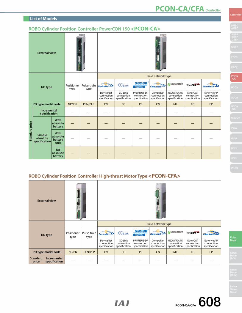
PCON-CA/CFA Controller
PCON-CA/CFA 608
PMECAMEC
Controller
Pulse Motor
Servo Motor (24V)
Servo Motor (200V)
LinearServo Motor
PSEP ASEPDSEP
MSEP
ERC3
ERC2
PCON-CA
PCON
ACON
SCON-CA
MSCON
PSEL
ASEL
SSEL
XSEL
PS-24
ROBO Cylinder Position Controller High-thrust Motor Type <PCON-CFA>
ROBO Cylinder Position Controller PowerCON 150 <PCON-CA>
External view
I/O type Positioner type
Pulse-train type
Field network type
DeviceNet connection
specification
CC-Link connection
specification
PROFIBUS-DP connection
specification
CompoNet connection
specification
MECHATROLINK connection
specification
EtherCAT connection
specification
EtherNet/IP connection
specification
I/O type model code NP/PN PLN/PLP DV CC PR CN ML EC EP
Standardprice
Incrementalspecification — — — — — — — — —
List of Models
External view
I/O type Positioner type
Pulse-train type
Field network type
DeviceNet connection
specification
CC-Link connection
specification
PROFIBUS-DP connection
specification
CompoNet connection
specification
MECHATROLINK connection
specification
EtherCAT connection
specification
EtherNet/IP connection
specification
I/O type model code NP/PN PLN/PLP DV CC PR CN ML EC EP
Incrementalspecification — — — — — — — — —
Simple absolute
specification
With absolute battery
— — — — — — — — —
With absolute battery
unit— — — — — — — — —
No absolute battery
— — — — — — — — —
Stan
dard
pri
ce
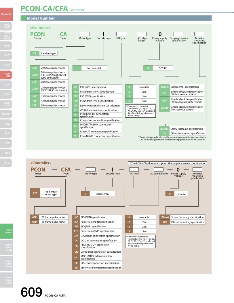
PCON-CA/CFA Controller
609 PCON-CA /CFA
PMECAMEC
Controller
Pulse Motor
Servo Motor (24V)
Servo Motor (200V)
LinearServo Motor
PSEP ASEPDSEP
MSEP
ERC3
ERC2
PCON-CA
PCON
ACON
SCON-CA
MSCON
PSEL
ASEL
SSEL
XSEL
PS-24
Model Number
PCON CA I 0 I/O type I/O cable
lengthMotor typeSeries Type Power supply
voltageActuator
mounting specification
Simple absolute specification
Encode type
* The mounting specification for the absolute battery unit (screws mounting or DIN rail mounting) conforms to the mounting specification for the controller.
<Controller>
* If a network connection specification (I/O type = DV, CC, PR, CN, ML, EC or EP) is selected, the I/O cable length becomes “0” (no cable).
NP PIO (NPN) specification
PLN Pulse-train (NPN) specification
PN PIO (PNP) specification
PLP Pulse-train (PNP) specification
DV DeviceNet connection specification
CC CC-Link connection specification
PR PROFIBUS-DP connection specification
CN CompoNet connection specification
ML MECHATROLINK connection specification
EC EtherCAT connection specification
EP EtherNet/IP connection specification
20P 20 frame pulse motor
20SP20 frame pulse motor(RCP3-RA2 high-thrust type dedicated)
28P 28 frame pulse motor
28SP 28 frame pulse motor(RCP2-RA3C dedicated)
35P 35 frame pulse motor
42P 42 frame pulse motor
56P 56 frame pulse motor
0 No cable
2 2 m
3 3 m
5 5 m
(Blank) Screw fastening specification
DN DIN rail mounting specification
(Blank) Incremental specification
AB Simple absolute specification(With absolute battery)
ABU Simple absolute specification(With absolute battery unit)
ABUN Simple absolute specification(No absolute battery)
CA Standard type
I Incremental 0 DC24V
PCON CFA I 0 I/O type I/O cable lengthMotor typeSeries Type Power supply
voltageActuator
mounting specification
Encode type
<Controller>
* If a network connection specification (I/O type = DV, CC, PR, CN, ML, EC or EP) is selected, the I/O cable length becomes “0” (no cable).
* The PCON-CFA does not support the simple absolute specification.
NP PIO (NPN) specification
PLN Pulse-train (NPN) specification
PN PIO (PNP) specification
PLP Pulse-train (PNP) specification
DV DeviceNet connection specification
CC CC-Link connection specification
PR PROFIBUS-DP connection specification
CN CompoNet connection specification
ML MECHATROLINK connection specification
EC EtherCAT connection specification
EP EtherNet/IP connection specification
0 No cable
2 2 m
3 3 m
5 5 m
(Blank) Screw fastening specification
DN DIN rail mounting specification
60P 60 frame pulse motor
86P 86 frame pulse motor
CFA High-thrust motor type I Incremental 0 DC24V
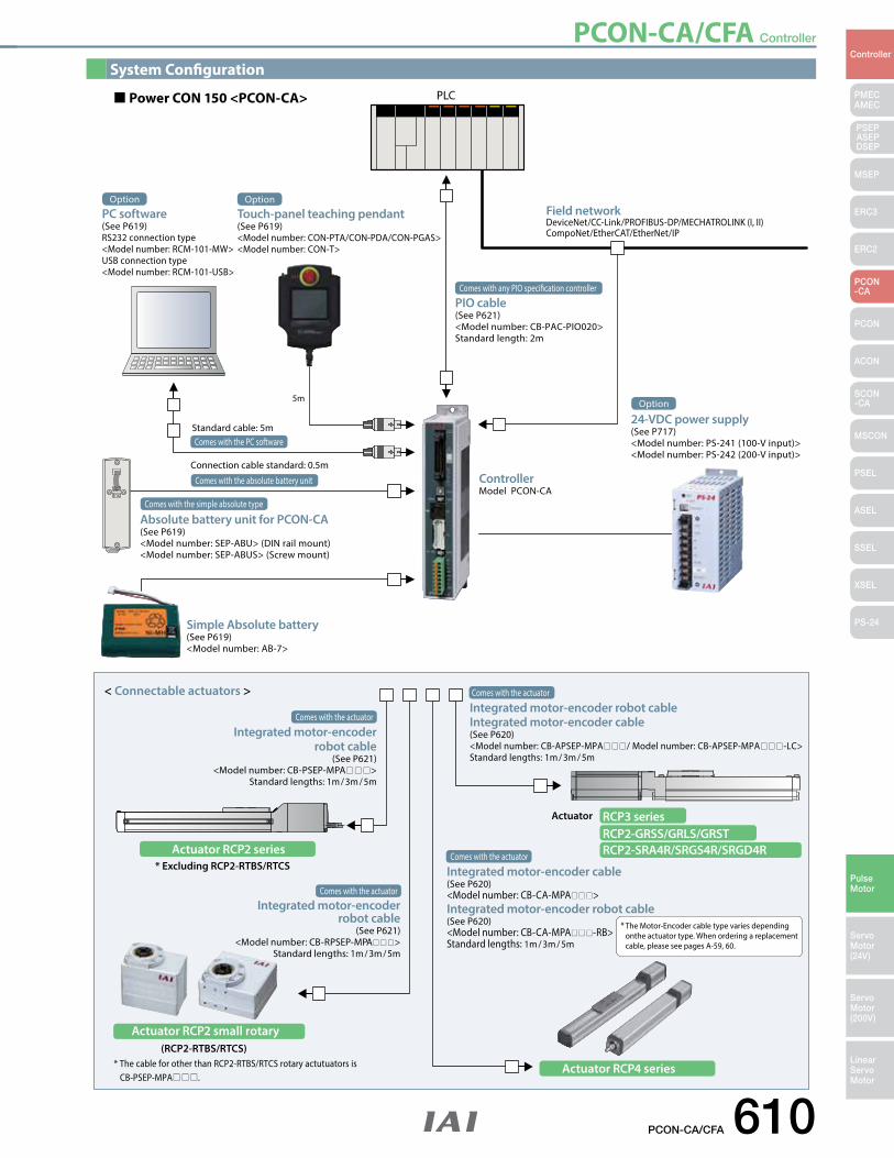
PCON-CA/CFA Controller
PCON-CA/CFA 610
PMECAMEC
Controller
Pulse Motor
Servo Motor (24V)
Servo Motor (200V)
LinearServo Motor
PSEP ASEPDSEP
MSEP
ERC3
ERC2
PCON-CA
PCON
ACON
SCON-CA
MSCON
PSEL
ASEL
SSEL
XSEL
PS-24
Actuator RCP4 series
Actuator RCP2 series
Actuator RCP2 small rotary
Comes with the absolute battery unit
Connection cable standard: 0.5m
Comes with the PC softwareStandard cable: 5m
The Motor-Encoder cable type varies depending onthe actuator type. When ordering a replacement cable, please see pages A-59, 60.
*
(RCP2-RTBS/RTCS)* The cable for other than RCP2-RTBS/RTCS rotary actutuators is CB-PSEP-MPA.
< Connectable actuators >
* Excluding RCP2-RTBS/RTCS
Actuator RCP3 seriesRCP2-GRSS/GRLS/GRSTRCP2-SRA4R/SRGS4R/SRGD4R
5m
PLC
System Conguration
Power CON 150 <PCON-CA>
Option
PC software(See P619)RS232 connection type<Model number: RCM-101-MW>USB connection type<Model number: RCM-101-USB>
Option
Touch-panel teaching pendant(See P619)<Model number: CON-PTA/CON-PDA/CON-PGAS><Model number: CON-T>
Field network DeviceNet/CC-Link/PROFIBUS-DP/MECHATROLINK (I, II)CompoNet/EtherCAT/EtherNet/IP
Comes with any PIO specication controller
PIO cable(See P621)<Model number: CB-PAC-PIO020>Standard length: 2m
Option
24-VDC power supply(See P717)<Model number: PS-241 (100-V input)><Model number: PS-242 (200-V input)>
ControllerModel PCON-CA
Comes with the simple absolute type
Absolute battery unit for PCON-CA(See P619)<Model number: SEP-ABU> (DIN rail mount) <Model number: SEP-ABUS> (Screw mount)
Simple Absolute battery(See P619)<Model number: AB-7>
Comes with the actuator
Integrated motor-encoderrobot cable
(See P621)<Model number: CB-PSEP-MPA>
Standard lengths: 1m / 3m / 5m
Comes with the actuator
Integrated motor-encoder robot cableIntegrated motor-encoder cable(See P620)<Model number: CB-APSEP-MPA/ Model number: CB-APSEP-MPA-LC>Standard lengths: 1m / 3m / 5m
Comes with the actuator
Integrated motor-encoderrobot cable
(See P621)<Model number: CB-RPSEP-MPA>
Standard lengths: 1m / 3m / 5m
Comes with the actuator
Integrated motor-encoder cable(See P620)<Model number: CB-CA-MPA>Integrated motor-encoder robot cable(See P620)<Model number: CB-CA-MPA-RB>Standard lengths: 1m / 3m / 5m
System Configuration
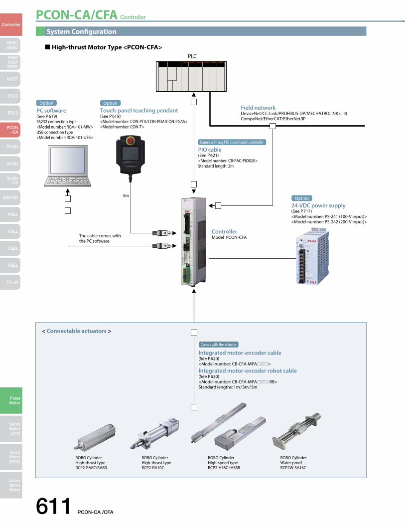
PCON-CA/CFA Controller
611 PCON-CA /CFA
PMECAMEC
Controller
Pulse Motor
Servo Motor (24V)
Servo Motor (200V)
LinearServo Motor
PSEP ASEPDSEP
MSEP
ERC3
ERC2
PCON-CA
PCON
ACON
SCON-CA
MSCON
PSEL
ASEL
SSEL
XSEL
PS-24
System Configuration
The cable comes withthe PC software
5m
PLC
High-thrust Motor Type <PCON-CFA>
ROBO CylinderWater-proofRCP2W-SA16C
ROBO CylinderHigh-speed typeRCP2-HS8C/HS8R
ROBO CylinderHigh-thrust typeRCP2-RA10C
ROBO CylinderHigh-thrust typeRCP2-RA8C/RA8R
< Connectable actuators >
Option
PC software(See P619)RS232 connection type <Model number: RCM-101-MW>USB connection type <Model number: RCM-101-USB>
Option
Touch-panel teaching pendant(See P619)<Model number: CON-PTA/CON-PDA/CON-PGAS><Model number: CON-T>
Field network DeviceNet/CC-Link/PROFIBUS-DP/MECHATROLINK (I, II)CompoNet/EtherCAT/EtherNet/IP
Comes with any PIO specication controller
PIO cable(See P621)<Model number: CB-PAC-PIO020>Standard length: 2m
Option
24-VDC power supply(See P717)<Model number: PS-241 (100-V input)><Model number: PS-242 (200-V input)>
ControllerModel PCON-CFA
Comes with the actuator
Integrated motor-encoder cable(See P620)<Model number: CB-CFA-MPA>
Integrated motor-encoder robot cable(See P620)<Model number: CB-CFA-MPA-RB>Standard lengths: 1m/3m/5m
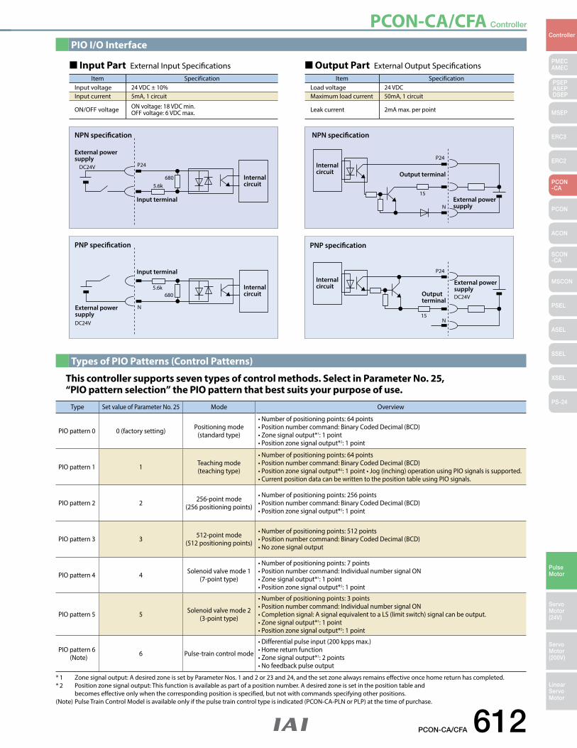
PCON-CA/CFA Controller
PCON-CA/CFA 612
PMECAMEC
Controller
Pulse Motor
Servo Motor (24V)
Servo Motor (200V)
LinearServo Motor
PSEP ASEPDSEP
MSEP
ERC3
ERC2
PCON-CA
PCON
ACON
SCON-CA
MSCON
PSEL
ASEL
SSEL
XSEL
PS-24
PIO I/O Interface
Types of PIO Patterns (Control Patterns)
Item SpecificationInput voltage 24 VDC ± 10%Input current 5mA, 1 circuit
ON/OFF voltage ON voltage: 18 VDC min.OFF voltage: 6 VDC max.
Item SpecificationLoad voltage 24 VDCMaximum load current 50mA, 1 circuit
Leak current 2mA max. per point
Input Part External Input Specifications Output Part External Output Specifications
This controller supports seven types of control methods. Select in Parameter No. 25, “PIO pattern selection” the PIO pattern that best suits your purpose of use.
Type Set value of Parameter No. 25 Mode Overview
PIO pattern 0 0 (factory setting) Positioning mode (standard type)
•Numberofpositioningpoints:64points•Positionnumbercommand:BinaryCodedDecimal(BCD)•Zonesignaloutput*1: 1 point •Positionzonesignaloutput*2: 1 point
PIO pattern 1 1 Teaching mode (teaching type)
•Numberofpositioningpoints:64points•Positionnumbercommand:BinaryCodedDecimal(BCD)•Positionzonesignaloutput*2:1point•Jog(inching)operationusingPIOsignalsissupported.•CurrentpositiondatacanbewrittentothepositiontableusingPIOsignals.
PIO pattern 2 2 256-point mode (256 positioning points)
•Numberofpositioningpoints:256points•Positionnumbercommand:BinaryCodedDecimal(BCD)•Positionzonesignaloutput*2: 1 point
PIO pattern 3 3 512-point mode (512 positioning points)
•Numberofpositioningpoints:512points•Positionnumbercommand:BinaryCodedDecimal(BCD)•Nozonesignaloutput
PIO pattern 4 4 Solenoid valve mode 1 (7-point type)
•Numberofpositioningpoints:7points•Positionnumbercommand:IndividualnumbersignalON•Zonesignaloutput*1: 1 point •Positionzonesignaloutput*2: 1 point
PIO pattern 5 5 Solenoid valve mode 2 (3-point type)
•Numberofpositioningpoints:3points•Positionnumbercommand:IndividualnumbersignalON•Completionsignal:AsignalequivalenttoaLS(limitswitch)signalcanbeoutput.•Zonesignaloutput*1: 1 point •Positionzonesignaloutput*2: 1 point
PIO pattern 6(Note) 6 Pulse-train control mode
•Differentialpulseinput(200kppsmax.)•Homereturnfunction•Zonesignaloutput*1: 2 points•Nofeedbackpulseoutput
* 1 Zone signal output: A desired zone is set by Parameter Nos. 1 and 2 or 23 and 24, and the set zone always remains effective once home return has completed. * 2 Position zone signal output: This function is available as part of a position number. A desired zone is set in the position table and becomes effective only when the corresponding position is specified, but not with commands specifying other positions.(Note) Pulse Train Control Model is available only if the pulse train control type is indicated (PCON-CA-PLN or PLP) at the time of purchase.
NPN specification
External power supply
Input terminal
P24DC24V
6805.6k
Internal circuit
DC24V
External power supply
Input terminal
6805.6k Internal
circuit
PNP specification
NLoad
Outputterminal
PNP specification
Internal circuit
15N
P24
DC24V
External power supply
DC24V
Load
NExternal power supply
Output terminal
15
P24Internal circuit
NPN specification
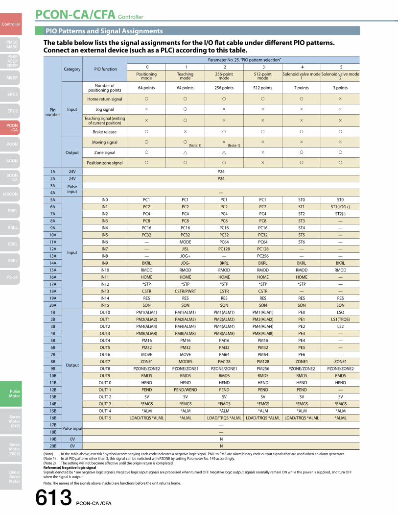
PCON-CA/CFA Controller
613 PCON-CA /CFA
PMECAMEC
Controller
Pulse Motor
Servo Motor (24V)
Servo Motor (200V)
LinearServo Motor
PSEP ASEPDSEP
MSEP
ERC3
ERC2
PCON-CA
PCON
ACON
SCON-CA
MSCON
PSEL
ASEL
SSEL
XSEL
PS-24
Pin number
Category PIO function
Parameter No. 25, “PIO pattern selection”
0 1 2 3 4 5
Positioning mode
Teaching mode
256-point mode
512-point mode
Solenoid valve mode 1
Solenoid valve mode 2
Input
Number of positioning points 64 points 64 points 256 points 512 points 7 points 3 points
Home return signal
Jog signal
Teaching signal (writing of current position)
Brake release
Output
Moving signal
Zone signal
Position zone signal
1A 24V P24
2A 24V P24
3A Pulse input
—
4A —
5A
Input
IN0 PC1 PC1 PC1 PC1 ST0 ST0
6A IN1 PC2 PC2 PC2 PC2 ST1 ST1(JOG+)
7A IN2 PC4 PC4 PC4 PC4 ST2 ST2(-)
8A IN3 PC8 PC8 PC8 PC8 ST3 —
9A IN4 PC16 PC16 PC16 PC16 ST4 —
10A IN5 PC32 PC32 PC32 PC32 ST5 —
11A IN6 — MODE PC64 PC64 ST6 —
12A IN7 — JISL PC128 PC128 — —
13A IN8 — JOG+ — PC256 — —
14A IN9 BKRL JOG- BKRL BKRL BKRL BKRL
15A IN10 RMOD RMOD RMOD RMOD RMOD RMOD
16A IN11 HOME HOME HOME HOME HOME —
17A IN12 *STP *STP *STP *STP *STP —
18A IN13 CSTR CSTR/PWRT CSTR CSTR — —
19A IN14 RES RES RES RES RES RES
20A IN15 SON SON SON SON SON SON
1B
Output
OUT0 PM1(ALM1) PM1(ALM1) PM1(ALM1) PM1(ALM1) PE0 LSO
2B OUT1 PM2(ALM2) PM2(ALM2) PM2(ALM2) PM2(ALM2) PE1 LS1(TRQS)
3B OUT2 PM4(ALM4) PM4(ALM4) PM4(ALM4) PM4(ALM4) PE2 LS2
4B OUT3 PM8(ALM8) PM8(ALM8) PM8(ALM8) PM8(ALM8) PE3 —
5B OUT4 PM16 PM16 PM16 PM16 PE4 —
6B OUT5 PM32 PM32 PM32 PM32 PE5 —
7B OUT6 MOVE MOVE PM64 PM64 PE6 —
8B OUT7 ZONE1 MODES PM128 PM128 ZONE1 ZONE1
9B OUT8 PZONE/ZONE2 PZONE/ZONE1 PZONE/ZONE1 PM256 PZONE/ZONE2 PZONE/ZONE2
10B OUT9 RMDS RMDS RMDS RMDS RMDS RMDS
11B OUT10 HEND HEND HEND HEND HEND HEND
12B OUT11 PEND PEND/WEND PEND PEND PEND —
13B OUT12 SV SV SV SV SV SV
14B OUT13 *EMGS *EMGS *EMGS *EMGS *EMGS *EMGS
15B OUT14 *ALM *ALM *ALM *ALM *ALM *ALM
16B OUT15 LOAD/TRQS *ALML *ALML LOAD/TRQS *ALML LOAD/TRQS *ALML LOAD/TRQS *ALML *ALML
17BPulse input
—
18B —
19B 0V N
20B 0V N
(Note 1) (Note 1)
PIO Patterns and Signal Assignments
The table below lists the signal assignments for the I/O flat cable under different PIO patterns. Connect an external device (such as a PLC) according to this table.
(Note) In the table above, asterisk * symbol accompanying each code indicates a negative logic signal. PM1 to PM8 are alarm binary code output signals that are used when an alarm generates. (Note 1) In all PIO patterns other than 3, this signal can be switched with PZONE by setting Parameter No. 149 accordingly.(Note 2) The setting will not become effective until the origin return is completed.Reference) Negative logic signal Signals denoted by * are negative logic signals. Negative logic input signals are processed when turned OFF. Negative logic output signals normally remain ON while the power is supplied, and turn OFF when the signal is output.
Note: The names of the signals above inside () are functions before the unit returns home.
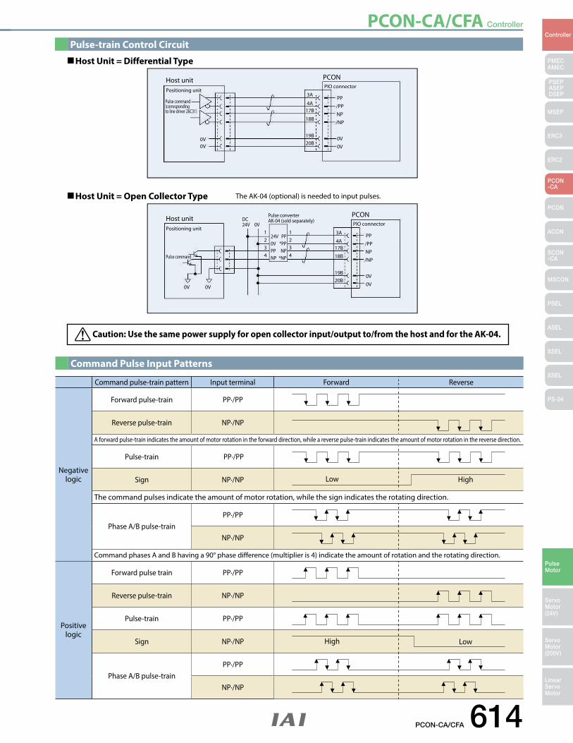
PCON-CA/CFA Controller
PCON-CA/CFA 614
PMECAMEC
Controller
Pulse Motor
Servo Motor (24V)
Servo Motor (200V)
LinearServo Motor
PSEP ASEPDSEP
MSEP
ERC3
ERC2
PCON-CA
PCON
ACON
SCON-CA
MSCON
PSEL
ASEL
SSEL
XSEL
PS-24
Command pulse-train pattern Input terminal Forward Reverse
Negative logic
Forward pulse-train PP·/PP
Reverse pulse-train NP·/NP
A forward pulse-train indicates the amount of motor rotation in the forward direction, while a reverse pulse-train indicates the amount of motor rotation in the reverse direction.
Pulse-train PP·/PP
Sign NP·/NP
The command pulses indicate the amount of motor rotation, while the sign indicates the rotating direction.
Phase A/B pulse-train PP·/PP
NP·/NP
Command phases A and B having a 90° phase difference (multiplier is 4) indicate the amount of rotation and the rotating direction.
Positive logic
Forward pulse train PP·/PP
Reverse pulse-train NP·/NP
Pulse-train PP·/PP
Sign NP·/NP
Phase A/B pulse-train PP·/PP
NP·/NP
Low High
High Low
Pulse-train Control Circuit
Command Pulse Input Patterns
Host unit PCON
Positioning unitPIO connector
Pulse command (corresponding to line driver 26C31)
0V
PP/PPNP/NP
0V0V
3A
4A17B
18B
19B20B0V
Host unitPositioning unit
PCONPIO connector
Pulse command
PP/PPNP/NP
0V0V
24V0VPPNP
1234
1234
PP*PPNP
*NP
3A
4A17B
18B
19B20B
0V 0V
DC24V
Pulse converter AK-04 (sold separately)
0V
Host Unit = Differential Type
Host Unit = Open Collector Type The AK-04 (optional) is needed to input pulses.
Caution: Use the same power supply for open collector input/output to/from the host and for the AK-04.
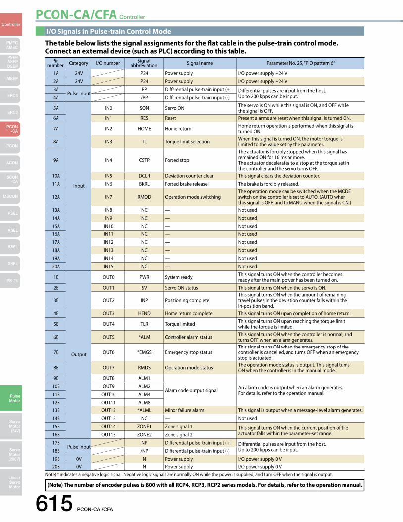
PCON-CA/CFA Controller
615 PCON-CA /CFA
PMECAMEC
Controller
Pulse Motor
Servo Motor (24V)
Servo Motor (200V)
LinearServo Motor
PSEP ASEPDSEP
MSEP
ERC3
ERC2
PCON-CA
PCON
ACON
SCON-CA
MSCON
PSEL
ASEL
SSEL
XSEL
PS-24
I/O Signals in Pulse-train Control Mode
(Note) The number of encoder pulses is 800 with all RCP4, RCP3, RCP2 series models. For details, refer to the operation manual.
The table below lists the signal assignments for the flat cable in the pulse-train control mode. Connect an external device (such as PLC) according to this table.
Pin number Category I/O number Signal
abbreviation Signal name Parameter No. 25, “PIO pattern 6”
1A 24V P24 Power supply I/O power supply +24 V
2A 24V P24 Power supply I/O power supply +24 V
3APulse input
PP Differential pulse-train input (+) Differential pulses are input from the host. Up to 200 kpps can be input.4A /PP Differential pulse-train input (-)
5A
Input
IN0 SON Servo ON The servo is ON while this signal is ON, and OFF while the signal is OFF.
6A IN1 RES Reset Present alarms are reset when this signal is turned ON.
7A IN2 HOME Home return Home return operation is performed when this signal is turned ON.
8A IN3 TL Torque limit selection When this signal is turned ON, the motor torque is limited to the value set by the parameter.
9A IN4 CSTP Forced stop
The actuator is forcibly stopped when this signal has remained ON for 16 ms or more. The actuator decelerates to a stop at the torque set in the controller and the servo turns OFF.
10A IN5 DCLR Deviation counter clear This signal clears the deviation counter.
11A IN6 BKRL Forced brake release The brake is forcibly released.
12A IN7 RMOD Operation mode switchingThe operation mode can be switched when the MODE switch on the controller is set to AUTO. (AUTO when this signal is OFF, and to MANU when the signal is ON.)
13A IN8 NC — Not used
14A IN9 NC — Not used
15A IN10 NC — Not used
16A IN11 NC — Not used
17A IN12 NC — Not used
18A IN13 NC — Not used
19A IN14 NC — Not used
20A IN15 NC — Not used
1B
Output
OUT0 PWR System ready This signal turns ON when the controller becomes ready after the main power has been turned on.
2B OUT1 SV Servo ON status This signal turns ON when the servo is ON.
3B OUT2 INP Positioning completeThis signal turns ON when the amount of remaining travel pulses in the deviation counter falls within the in-position band.
4B OUT3 HEND Home return complete This signal turns ON upon completion of home return.
5B OUT4 TLR Torque limited This signal turns ON upon reaching the torque limit while the torque is limited.
6B OUT5 *ALM Controller alarm status This signal turns ON when the controller is normal, and turns OFF when an alarm generates.
7B OUT6 *EMGS Emergency stop status This signal turns ON when the emergency stop of the controller is cancelled, and turns OFF when an emergency stop is actuated.
8B OUT7 RMDS Operation mode status The operation mode status is output. This signal turns ON when the controller is in the manual mode.
9B OUT8 ALM1
Alarm code output signal An alarm code is output when an alarm generates. For details, refer to the operation manual.
10B OUT9 ALM2
11B OUT10 ALM4
12B OUT11 ALM8
13B OUT12 *ALML Minor failure alarm This signal is output when a message-level alarm generates.
14B OUT13 NC — Not used
15B OUT14 ZONE1 Zone signal 1 This signal turns ON when the current position of the actuator falls within the parameter-set range.16B OUT15 ZONE2 Zone signal 2
17BPulse input
NP Differential pulse-train input (+) Differential pulses are input from the host.Up to 200 kpps can be input. 18B /NP Differential pulse-train input (-)
19B 0V N Power supply I/O power supply 0 V
20B 0V N Power supply I/O power supply 0 VNote) * indicates a negative logic signal. Negative logic signals are normally ON while the power is supplied, and turn OFF when the signal is output.
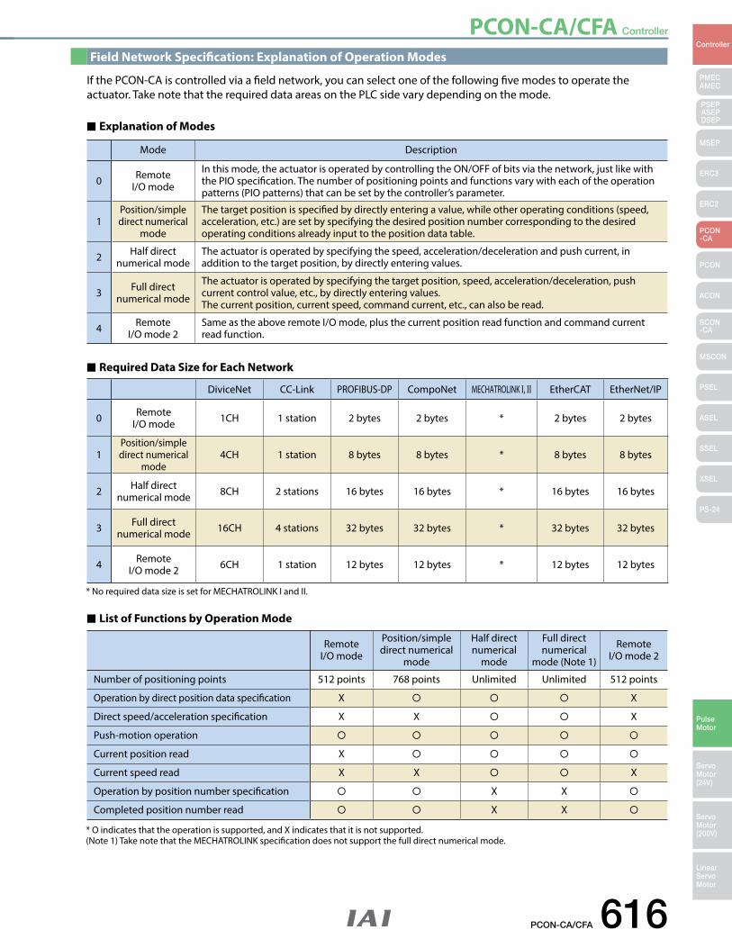
PCON-CA/CFA Controller
PCON-CA/CFA 616
PMECAMEC
Controller
Pulse Motor
Servo Motor (24V)
Servo Motor (200V)
LinearServo Motor
PSEP ASEPDSEP
MSEP
ERC3
ERC2
PCON-CA
PCON
ACON
SCON-CA
MSCON
PSEL
ASEL
SSEL
XSEL
PS-24
Field Network Specification: Explanation of Operation Modes
If the PCON-CA is controlled via a field network, you can select one of the following five modes to operate the actuator. Take note that the required data areas on the PLC side vary depending on the mode.
Explanation of Modes
List of Functions by Operation Mode
Required Data Size for Each Network
DiviceNet CC-Link PROFIBUS-DP CompoNet MECHATROLINK I, II EtherCAT EtherNet/IP
0 Remote I/O mode 1CH 1 station 2 bytes 2 bytes * 2 bytes 2 bytes
1Position/simple direct numerical
mode4CH 1 station 8 bytes 8 bytes * 8 bytes 8 bytes
2 Half direct numerical mode 8CH 2 stations 16 bytes 16 bytes * 16 bytes 16 bytes
3 Full direct numerical mode 16CH 4 stations 32 bytes 32 bytes * 32 bytes 32 bytes
4 Remote I/O mode 2 6CH 1 station 12 bytes 12 bytes * 12 bytes 12 bytes
Remote I/O mode
Position/simple direct numerical
mode
Half direct numerical
mode
Full direct numerical
mode (Note 1)
Remote I/O mode 2
Number of positioning points 512 points 768 points Unlimited Unlimited 512 points
Operation by direct position data specification X X
Direct speed/acceleration specification X X X
Push-motion operation
Current position read X
Current speed read X X X
Operation by position number specification X X
Completed position number read X X
Mode Description
0 Remote I/O mode
In this mode, the actuator is operated by controlling the ON/OFF of bits via the network, just like with the PIO specification. The number of positioning points and functions vary with each of the operation patterns (PIO patterns) that can be set by the controller’s parameter.
1Position/simple direct numerical
mode
The target position is specified by directly entering a value, while other operating conditions (speed, acceleration, etc.) are set by specifying the desired position number corresponding to the desired operating conditions already input to the position data table.
2 Half direct numerical mode
The actuator is operated by specifying the speed, acceleration/deceleration and push current, in addition to the target position, by directly entering values.
3 Full direct numerical mode
The actuator is operated by specifying the target position, speed, acceleration/deceleration, push current control value, etc., by directly entering values.The current position, current speed, command current, etc., can also be read.
4 Remote I/O mode 2
Same as the above remote I/O mode, plus the current position read function and command current read function.
* O indicates that the operation is supported, and X indicates that it is not supported. (Note 1) Take note that the MECHATROLINK specification does not support the full direct numerical mode.
* No required data size is set for MECHATROLINK I and II.
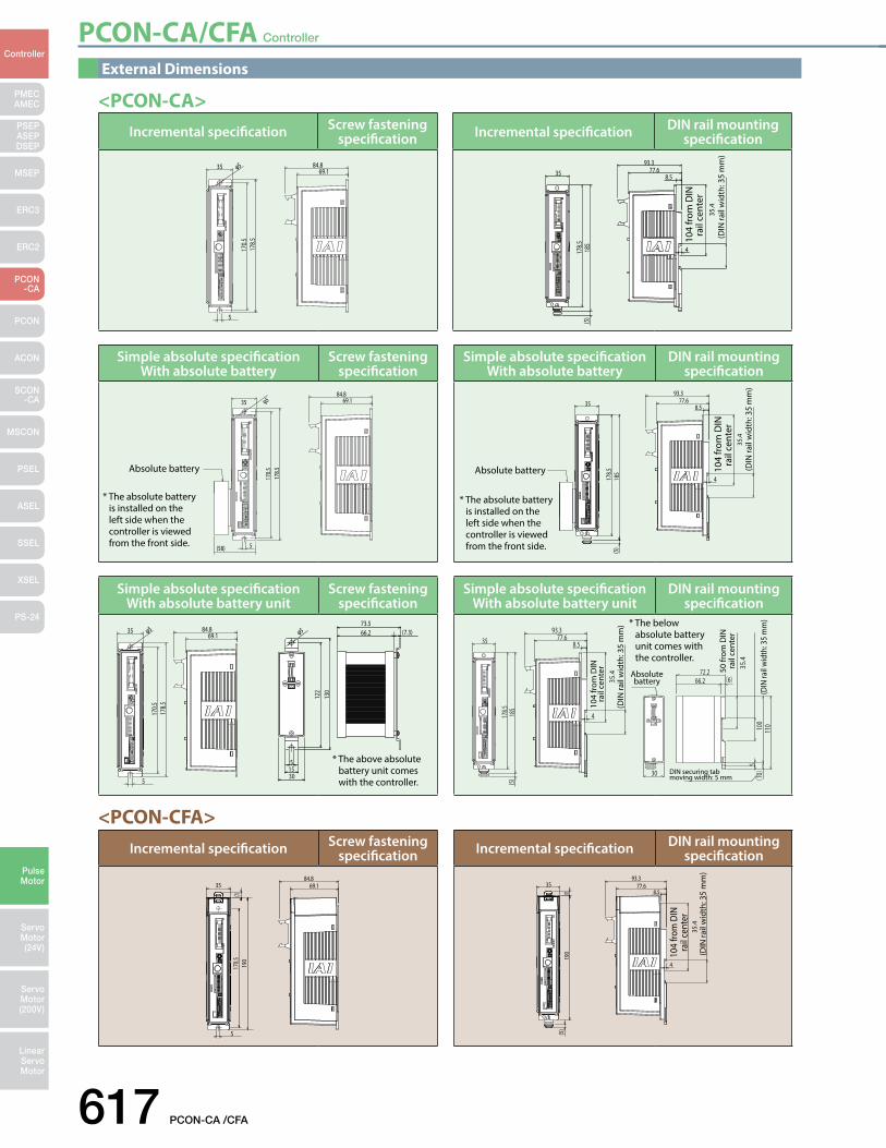
PCON-CA/CFA Controller
617 PCON-CA /CFA
PMECAMEC
Controller
Pulse Motor
Servo Motor (24V)
Servo Motor (200V)
LinearServo Motor
PSEP ASEPDSEP
MSEP
ERC3
ERC2
PCON-CA
PCON
ACON
SCON-CA
MSCON
PSEL
ASEL
SSEL
XSEL
PS-24
<PCON-CA>
<PCON-CFA>
Simple absolute specificationWith absolute battery
Screw fastening specification
* The absolute battery is installed on the left side when the controller is viewed from the front side.
178.
517
0.5
35
5
84.869.1φ 5
(58)
Absolute battery
Simple absolute specificationWith absolute battery
DIN rail mounting specification
* The absolute battery is installed on the left side when the controller is viewed from the front side.
35
185
178.
5(5
)
93.377.6
8.5
4
35.4
Absolute battery 104
from
DIN
ra
il ce
nter
(DIN
rail
wid
th: 3
5 m
m)
Incremental specification Screw fastening specification
178.
517
0.5
35
5
84.869.1φ 5
Incremental specification DIN rail mounting specification
35
(5)
93.377.6
8.5
4
35.4
185
178.
5 104
from
DIN
ra
il ce
nter
(DIN
rail
wid
th: 3
5 m
m)
Simple absolute specificationWith absolute battery unit
Screw fastening specification
φ 5
122
51530
66.273.5
(7.3)
130
178.
517
0.5
35
5
φ 5 84.869.1
* The above absolute battery unit comes with the controller.
Simple absolute specificationWith absolute battery unit
DIN rail mounting specification
(10)
100
110
35.4
5
72.2
30
66.2 (6)
35
(5)185
178.5
93.377.6
8.5
4
35.4
* The below absolute battery unit comes with the controller.
Absolutebattery
104
from
DIN
ra
il ce
nter
(DIN
rail
wid
th: 3
5 m
m)
(DIN
rail
wid
th: 3
5 m
m)
DIN securing tab moving width: 5 mm
50 fr
om D
IN
rail
cent
er
Incremental specification Screw fastening specification
84.835
(7)19
017
0.5
69.1
5
Incremental specification DIN rail mounting specification
35.4
(7)(5
)19
0
3593.3
77.68.5
4
104
from
DIN
ra
il ce
nter
(DIN
rail
wid
th: 3
5 m
m)
External Dimensions
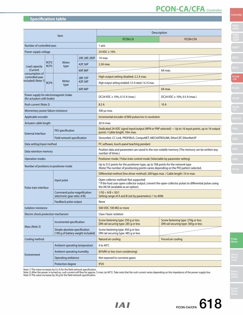
PCON-CA/CFA Controller
PCON-CA/CFA 618
PMECAMEC
Controller
Pulse Motor
Servo Motor (24V)
Servo Motor (200V)
LinearServo Motor
PSEP ASEPDSEP
MSEP
ERC3
ERC2
PCON-CA
PCON
ACON
SCON-CA
MSCON
PSEL
ASEL
SSEL
XSEL
PS-24
Specification table
ItemDescription
PCON-CA PCON-CFA
Number of controlled axes 1 axis
Power supply voltage 24 VDC ± 10%
Load capacity(Current
consumption of controlled axes
included) (Note 1)
RCP2RCP3
Motor type
20P, 28P, 28SP 1A max.
42P, 56P 2.2A max.
60P, 86P 6A max.
RCP4 Motor type
28P, 35P42P, 56P
High-output setting disabled: 2.2 A max.
High-output setting enabled: 3.5 A rated / 4.2 A max.
60P, 86P 6A max.
Power supply for electromagnetic brake(for actuators with brake) DC24 VDC ± 10%, 0.15 A (max.) DC24 VDC ± 10%, 0.5 A (max.)
Rush current (Note 2) 8.3 A 10 A
Momentary power failure resistance 500 μs max.
Applicable encoder Incremental encoder of 800 pulses/rev in resolution
Actuator cable length 20 m max.
External interfacePIO specification Dedicated 24-VDC signal input/output (NPN or PNP selected) --- Up to 16 input points, up to 16 output
points / Cable length: 10m max.
Field network specification DeviceNet, CC-Link, PROFIBUS, CompoNET, MECHATROLINK, EtherCAT, EtherNet/IP
Data setting/input method PC software, touch-panel teaching pendant
Data retention memory Position data and parameters are saved in the non-volatile memory (The memory can be written any number of times.)
Operation modes Positioner mode / Pulse-train control mode (Selectable by parameter setting)
Number of positions in positioner mode Up to 512 points for the positioner type, up to 768 points for the network type (Note) The number of positioning points varies depending on the PIO pattern selected.
Pulse-train interface
Input pulse
Differential method (line driver method): 200 kpps max. / Cable length: 10 m max.
Open collector method: Not supported* If the host uses open-collector output, convert the open-collector pulses to differential pulses using the AK-04 (available as an option).
Command pulse magnification(electronic gear ratio: A/B)
1/50 < A/B < 50/1Setting range of A and B (set by parameters): 1 to 4096
Feedback pulse output None
Isolation resistance 500-VDC 100 MΩ or more
Electric shock protection mechanism Class I basic isolation
Mass (Note 3) Incremental specification Screw fastening type: 250 g or less
DIN rail securing type: 285 g or lessScrew fastening type: 270g or less DIN rail securing type: 305g or less
Simple absolute specification(190 g of battery weight included)
Screw fastening type: 450 g or lessDIN rail securing type: 485 g or less
Cooling method Natural air cooling Forced air cooling
Environment
Ambient operating temperature 0 to 40°C
Ambient operating humidity 85%RH or less (non-condensing)
Operating ambience Not exposed to corrosive gases
Protection degree IP20
Note 1) The value increases by 0.3 A for the field network specification. Note 2) After the power is turned on, rush current will flow for approx. 5 msec (at 40°C). Take note that the rush current varies depending on the impedance of the power-supply line. Note 3) The value increases by 30 g for the field network specification.
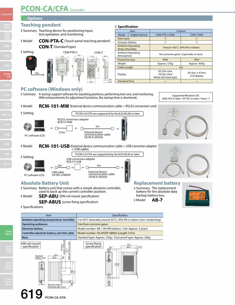
PCON-CA/CFA Controller
619 PCON-CA /CFA
PMECAMEC
Controller
Pulse Motor
Servo Motor (24V)
Servo Motor (200V)
LinearServo Motor
PSEP ASEPDSEP
MSEP
ERC3
ERC2
PCON-CA
PCON
ACON
SCON-CA
MSCON
PSEL
ASEL
SSEL
XSEL
PS-24
Options
Item Specification
Ambient operating temperature, humidity 0 to 40°C (desirably around 20°C), 95% RH or below (non-condensing)
Operating ambience Free from corrosive gases
Absolute battery Model number: AB-7 (Ni-MH battery / Life: Approx. 3 years)
Controller/absolute battery unit link cable Model number: CB-APSEP-AB005 (Length: 0.5m)
Mass Standard type: Approx. 230g / Dust-proof type: Approx. 260g
ø5
122
51530
66.273.5
(7.3)
130
(10)
100
110
50 fr
om
cent
er o
f DIN
rail
35.4
(DIN
rail
35m
m w
ide)
5
72.2
30 Moving range of DIN xing tabs: 5mm
Absolute battery unit 66.2 (6)
Screw fixing specification
DIN rail mount specification
PC software (Windows only)Summary A startup support software for inputting positions, performing test runs, and monitoring. With enhancements for adjustment functions, the startup time is shortened.
Model RCM-101-MW (External device communication cable + RS232 conversion unit)
Setting
Absolute Battery UnitSummary Battery unit that comes with a simple absolute controller, used to back up the current controller position. Model SEP-ABU (DIN rail mount specification)
SEP-ABUS (screw fixing specification)Specifications
Replacement batterySummary The replacement battery for the absolute data backup battery box.Model AB-7
Model RCM-101-USB (External device communication cable + USB converter adaptor + USB cable)
Setting
Teaching pendantSummary Teaching device for positioning input, test operation, and monitoring.
Model CON-PTA-C (Touch panel teaching pendant)
CON-T (Standard type)
Setting
PCON-CA/CFA are supported by Ver.8.03.00.00 or later
PCON-CA/CFA are supported by Ver.8.03.00.00 or later
Supported Windows OS: 2000 SP4 or later / XP SP2 or later / Vista / 7
Item ContentModel English Version CON-PTA-C-ENG CON-T-ENG
Data Input
Actuator Motion
Ambient Operating Temp./Humidity Temp 0~40°C; 85% RH or below
Ambient Operating Atmosphere No corrosive gases. Especially no dust.
Protective class IP40 IP54Weight Approx. 570g Approx. 400gCable Length 5m
Display65,536 color(16 bit color)
White LED back light
20 char. x 4 lines LCD display
Standard Price — —
Specification
CON-PTA-C CON-T
5m
RS232 conversion adapter RCB-CV-MW
External device communication cable CB-RCA-SIO050
0.3m
5m
PC software (CD)
External device communication cable CB-RCA-SIO050
USB conversion adapter RCB-CV-USB
USB cable CB-SEL-USB030
3m 5m
PC software (CD)

PCON-CA/CFA Controller
PCON-CA/CFA 620
PMECAMEC
Controller
Pulse Motor
Servo Motor (24V)
Servo Motor (200V)
LinearServo Motor
PSEP ASEPDSEP
MSEP
ERC3
ERC2
PCON-CA
PCON
ACON
SCON-CA
MSCON
PSEL
ASEL
SSEL
XSEL
PS-24
L
(10)
(26)
(18)
(30)
(45)
(ø8.
5)
(Front view)
*Refer to page A-59 for connectable actuators.
Minimum bend radius R: r = 68mm or larger (for movable use)Actuator side Controller side
Controller sideActuator side
NC
Black (label)[BK+](LS+)
White [ - ](A+)
[PCON](ACON)Pin numberA1B1A2B2A3B3A4B4A6B6A7B7A8B8A5B5A9B9
A10B10A11B11
Pin number12534678
1112131415169
102018171921242223
Black [ ØA ](U)White [VMM](V)
Brown [ Ø/A ](W)Green [ ØB ]( - )
Yellow [VMM]( - )Red [ Ø/B ]( - )
Orange [LS+](BK+)Gray [LS-](BK-)
Yellow [ - ](A-)Red [ A+ ](B+)Green [ A- ](B-)Black [ B+ ](Z+)Brown [ B- ](Z-)
Brown (label)[BK-](LS-)Green (label)[GNDLS](GNDLS)Red (label)[VPS](VPS)
White (label)[VCC](VCC)Yellow (label)[GND](GND)
Shield [FG](FG)NCNC
L
(10)
(10)
(23)
(10)
(26)
(Not
e 1)
(ø8.
5)
(Front view)
* The robot cable is designed for flex-resistance: Please use the robot cable if the cable has to be installed through the cable track.
*Refer to page A-59 for connectable actuators.
Minimum bend radius R: r = 80mm or larger (for movable use)Actuator side Controller side
Pin No. Signal name ColorA1 ØA/U Blue(Black)B1 VMM/V Orange (White)A2 Ø_A/W Green (Brown)B2 ØB/- Brown (Green)A3 VMM/- Gray (Yellow)B3 Ø_B/- Red (Red)A4 LS+/BK+ Black (Orange)B4 LS-/BK- Yellow (Gray)A6 -/A+ Blue (White)B6 -/A- Orange (Yellow)A7 A+/B+ Green (Red)B7 A-/B- Brown (Green)A8 B+/Z+ Gray (Black)B8 B-/Z- Red (Brown)A5 BK+/LS+ Blue (Black)B5 BK-/LS- Orange (Brown)A9 LS_GND Green (Green)B9 VPS Brown (Red)
A10 VCC Gray (White)B10 GND Red (Yellow)A11 — —B11 FG Black (—)
Pin No. Signal name Color1 ØA/U Blue (Black)2 VMM/V Orange (White)5 Ø_A/W Green (Brown)3 ØB/- Brown (Green)4 VMM/- Gray (Yellow)6 Ø_B/- Red (Red)7 LS+/BK+ Black (Orange)8 LS-/BK- Yellow (Gray)
11 -/A+ Blue (White)12 -/A- Orange (Yellow)13 A+/B+ Green (Red)14 A-/B- Brown (Green)15 B+/Z+ Gray (Black)16 B-/Z- Red (Brown)9 BK+/LS+ Blue (Black)
10 BK-/LS- Orange (Brown)20 LS_GND Green (Green)18 VPS Brown (Red)17 VCC Gray (White)19 GND Red (Yellow)21 — —22 — —23 — —24 FG Black (—)
* Color in ( ) indicates color of robot cable
Actuator side1-1827863-1 (AMP)
Controller sidePADP-24V-1-S (JST)
L
(10)
(26)
(15)
(25)
(15)
(14)
(20)
(14)
(ø8.
5)
123456
11
1278
131415169
102119182024172223
124536
Pin No. Pin No. Signal nameøA
VMMøB
VMMø/Aø/B
øAVMM
øBVMMø/Aø/B
NC
NCLS+LS-A+A-B+B-
BK+BK-VCCGNDVPSNCFGNCNCNC
Signal name
56
13141234
1617129
1110181578
NCNCLS+LS-A+A-B+B-
BK+BK-VCCGNDVPSNCFGNCNCNC
(Front view)
*Refer to page A-59 for connectable actuators.
Minimum bend radius R: r = 68mm or larger (for movable use)Actuator side Controller side
Actuator sideSLP -06V (JST)
Controller sidePADP-24V-1-S (JST)
Service parts
Integrated Motor-Encoder Robot Cable/ Motor-Encoder Cable for RCP2-RA10C/HS8/SA16C
Model CB-CFA-MPA /CB-CFA-MPA -RB * Enter the cable length (L) into. Compatible to a maximum of 20 meters. Ex.: 080 = 8m
Integrated Motor-Encoder Cable/ Motor-Encoder Robot Cable for RCP4
Model CB-CA-MPA /CB-CA-MPA -RB * Enter the cable length (L) into. Compatible to a maximum of 20 meters. Ex.: 080 = 8m
Integrated Motor-Encoder Robot Cable/ Motor-Encoder Cable for RCP3/RCA2 and others
Model CB-APSEP-MPA /CB-APSEP-MPA -LC * Enter the cable length (L) into. Compatible to a maximum of 20 meters. Ex.: 080 = 8m
(Note 1) If cable length is 5m or more, non-robotic cable is ø9.1 and robot cable is ø10.
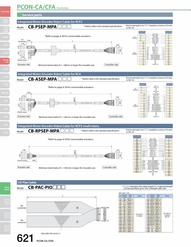
PCON-CA/CFA Controller
621 PCON-CA /CFA
PMECAMEC
Controller
Pulse Motor
Servo Motor (24V)
Servo Motor (200V)
LinearServo Motor
PSEP ASEPDSEP
MSEP
ERC3
ERC2
PCON-CA
PCON
ACON
SCON-CA
MSCON
PSEL
ASEL
SSEL
XSEL
PS-24
Service parts
No. Signal name
Cable color Wiring
1A 24V Brown - 1
Flat cable A (crimped)
2A 24V Red - 13A Pulse
InputOrange - 1
4A Yellow - 15A IN0 Green - 16A IN1 Blue - 17A IN2 Purple - 18A IN3 Gray - 19A IN4 White - 1
10A IN5 Black - 111A IN6 Brown - 212A IN7 Red - 213A IN8 Orange - 214A IN9 Yellow - 215A IN10 Green - 216A IN11 Blue - 217A IN12 Purple - 218A IN13 Gray - 219A IN14 White - 220A IN15 Black - 2
No. Signal name
Cable color Wiring
1B OUT0 Brown - 3
Flat cable B (crimped)AWG 28
2B OUT1 Red - 33B OUT2 Orange - 34B OUT3 Yellow - 35B OUT4 Green - 36B OUT5 Blue - 37B OUT6 Purple - 38B OUT7 Gray - 39B OUT8 White - 3
10B OUT9 Black - 311B OUT10 Brown - 412B OUT11 Red - 413B OUT12 Orange - 414B OUT13 Yellow - 415B OUT14 Green - 416B OUT15 Blue - 417B Pulse
InputPurple - 4
18B Gray - 419B 0V White - 420B 0V Black - 4
L
20A
1A
20B
1B
No connector
No connector
Flat cable (20 cores) x 2
HIF6-40D-1.27R
A
B
*indicates the cable length (L). A desired length can be specified up to 10m. Example: 080=8mModel CB-PAC-PIO
I/O Flat Cable
Integrated Motor-Encoder Robot Cable for RCP2
1st connector
* Robot cable is the standard specification.
L
(10)
(26)
(15)
(25)
(15)
(14)
(20)
(14)
(ø8.
5)
(Front view)
Model CB-PSEP-MPA * Enter the cable length (L) into . Compatible to a maximum of 20 meters. Ex.: 080 = 8m
*Refer to page A-59 for connectable actuators.
Minimum bend radius R: r = 68mm or larger (for movable use)Actuator side Controller side
Controller sideActuator side
Black [ ØA ]Pin number
124536
161756
13141234
10119
121578
18
White [ VMM ]Red [ ØB ]
Green [ VMM ]Brown [ Ø/A ]Yellow [ Ø/B ]Orange [ BK+ ]
Gray [ BK- ]NCNC
Black [ LS+ ]Brown [ LS- ]White [ A+ ]Yellow [ A- ]
Red [ B+ ]Green [ B- ]
White (label)[VCC]Yellow (label)[VPS]Red (label)[GND]
Green (label)[(Spare)]NCNCNC
Shield [ FG ]
Pin number1234569
10111278
131415161718192021222324
1stConnector
2ndConnector
* Robot cable is the standard specification.Model CB-ASEP-MPA *Enter the cable length (L) into . Compatible to a maximum of 20 meters. Ex.: 080 = 8m
*Refer to page A-59 for connectable actuators.
Integrated Motor-Encoder Robot Cable for RCA
Minimum bend radius R: r = 68 mm or larger (for movable use)Actuator side Controller side
L
(10)
(26)
(15)
(25)
(10)
(14)
(20)
(14)
(ø8.
5)
(Front view)
Red [ U ]12
3
18177
161234
1011141315658
129
Yellow [ V ]NCNC
Black [ W ]NC
Orange [ BK+ ]Gray [ BK- ]Black [ LS+ ]Brown [ LS- ]White [ A+ ]Yellow [ A- ]
Red [ B+ ]Green [ B- ]
Black (label)[Z+]Brown (label)[Z-]
White (label)[VCC]Yellow (label)[VPS]Red (label)[GND]
Green (label)[(Spare)]NCNCNC
Shield [ FG ]
123456789
101112131415161718192021222324
Controller side Actuator sidePin number Pin number
1stConnector
2ndConnector
* Robot cable is the standard specification.Model CB-RPSEP-MPA *Enter the cable length (L) into . Compatible to a maximum of 20 meters. Ex.: 080 = 8m
*Refer to page A-59 for connectable actuators.
Integrated Motor-Encoder Robot Cable for RCP2 small rotary
Minimum bend radius R: r = 68 mm or larger (for movable use)Actuator side Controller side
L
(10)
(26)
(45)
(18)
(30) (ø
8.5)
(Front view)
Black [ ØA ]Pin number
A1B1A2B2A3B3A6B6A7B7A8B8A4B4A5B5A9B9
A10B10A11B11
White [ VMM ]Brown [ Ø/A ]Green [ ØB ]
Yellow [ VMM ]Red [ Ø/B ]
Orange [ LS+ ]Gray [ LS- ]Red [ A+ ]
Green [ A- ]Black [ B+ ]Brown [ B- ]
NCNC
Black (label)[BK+]Brown (label)[BK-]
Green (label)[GNDLS]Red (label)[VPS]
White (label)[VCC]Yellow (label)[GND]
NCShield [ FG ](FG)
NCNC
Pin number12534678
13141516--9
102018171921242223
Controller sideActuator side
PCON-CA/CFA Controller
PCON-CA/CFA 622
PMECAMEC
Controller
Pulse Motor
Servo Motor (24V)
Servo Motor (200V)
LinearServo Motor
PSEP ASEPDSEP
MSEP
ERC3
ERC2
PCON-CA
PCON
ACON
SCON-CA
MSCON
PSEL
ASEL
SSEL
XSEL
PS-24
MEMO
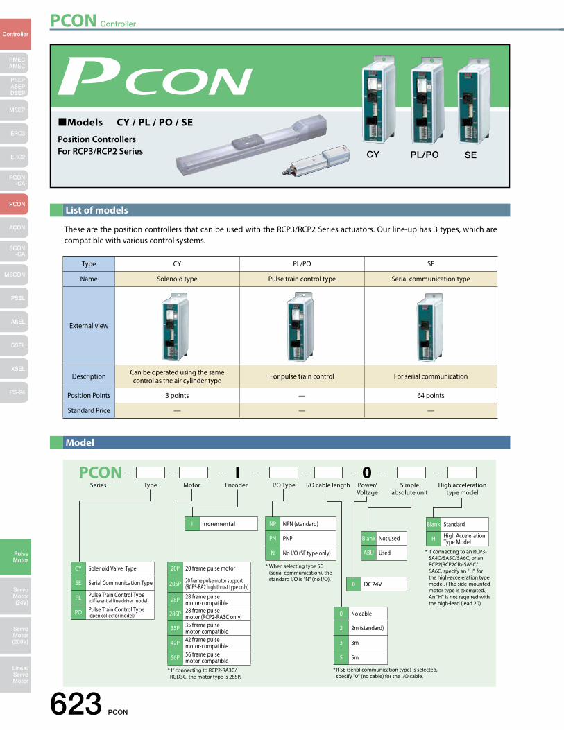
PCON Controller
623 PCON
PMECAMEC
Controller
Pulse Motor
Servo Motor (24V)
Servo Motor (200V)
LinearServo Motor
PSEP ASEPDSEP
MSEP
ERC3
ERC2
PCON-CA
PCON
ACON
SCON-CA
MSCON
PSEL
ASEL
SSEL
XSEL
PS-24
List of models
These are the position controllers that can be used with the RCP3/RCP2 Series actuators. Our line-up has 3 types, which are compatible with various control systems.
Model
PCON I 0TypeSeries Motor Encoder I/O Type I/O cable length Power/
VoltageSimple
absolute unitHigh acceleration
type model
I Incremental
0 DC24V
CY Solenoid Valve Type
SE Serial Communication Type
PL Pulse Train Control Type (differential line driver model)
PO Pulse Train Control Type(open collector model) 0 No cable
2 2m (standard)
3 3m
5 5m
NP NPN (standard)
PN PNP
N No I/O (SE type only)
Blank Not used
ABU Used
Blank Standard
H High Acceleration Type Model
20P 20 frame pulse motor
20SP 20 frame pulse motor support (RCP3-RA2 high thrust type only)
28P 28 frame pulse motor-compatible
28SP 28 frame pulse motor (RCP2-RA3C only)
35P 35 frame pulse motor-compatible
42P 42 frame pulse motor-compatible
56P 56 frame pulse motor-compatible
* If connecting to RCP2-RA3C/ RGD3C, the motor type is 28SP.
* When selecting type SE (serial communication), the standard I/O is "N" (no I/O).
* If SE (serial communication type) is selected, specify "0" (no cable) for the I/O cable.
* If connecting to an RCP3- SA4C/SA5C/SA6C, or an RCP2(RCP2CR)-SA5C/ SA6C, specify an "H", for the high-acceleration type model. (The side-mounted motor type is exempted.)
An "H" is not required with the high-lead (lead 20).
Models CY / PL / PO / SE
Position ControllersFor RCP3/RCP2 Series CY PL/PO SE
Type CY PL/PO SE
Name Solenoid type Pulse train control type Serial communication type
External view
Description Can be operated using the same control as the air cylinder type For pulse train control For serial communication
Position Points 3 points — 64 points
Standard Price — — —
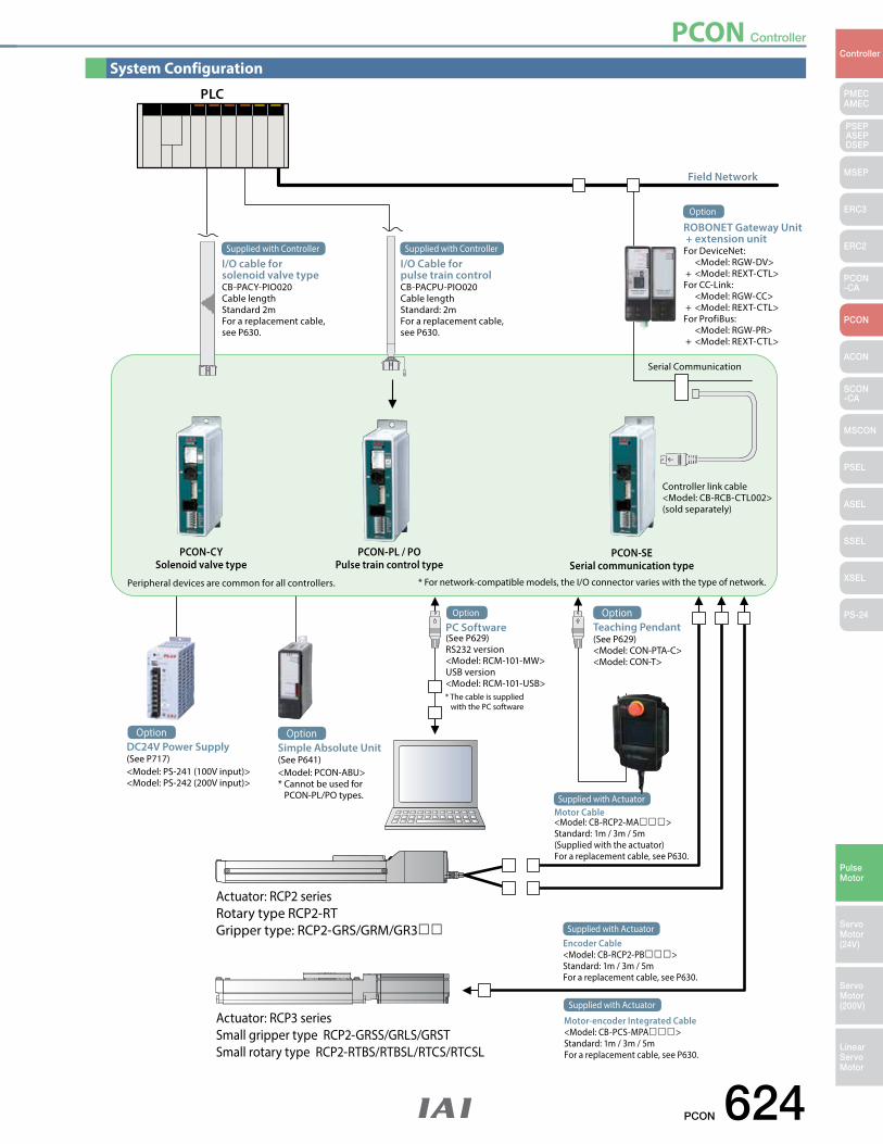
PCON Controller
PCON 624
PMECAMEC
Controller
Pulse Motor
Servo Motor (24V)
Servo Motor (200V)
LinearServo Motor
PSEP ASEPDSEP
MSEP
ERC3
ERC2
PCON-CA
PCON
ACON
SCON-CA
MSCON
PSEL
ASEL
SSEL
XSEL
PS-24
System Configuration
PLC
Actuator: RCP2 seriesRotary type RCP2-RTGripper type: RCP2-GRS/GRM/GR3
Actuator: RCP3 seriesSmall gripper type RCP2-GRSS/GRLS/GRSTSmall rotary type RCP2-RTBS/RTBSL/RTCS/RTCSL
Controller link cable<Model: CB-RCB-CTL002>(sold separately)
PCON-PL / POPulse train control type
PCON-SESerial communication type
Peripheral devices are common for all controllers.
PCON-CYSolenoid valve type
Field Network
I/O cable for solenoid valve typeCB-PACY-PIO020Cable lengthStandard 2mFor a replacement cable, see P630.
Supplied with Controller
Serial Communication
Supplied with Controller
I/O Cable for pulse train controlCB-PACPU-PIO020Cable lengthStandard: 2mFor a replacement cable, see P630.
ROBONET Gateway Unit + extension unitFor DeviceNet: <Model: RGW-DV> + <Model: REXT-CTL>For CC-Link: <Model: RGW-CC> + <Model: REXT-CTL>For ProfiBus: <Model: RGW-PR> + <Model: REXT-CTL>
Option
Motor Cable<Model: CB-RCP2-MA>Standard: 1m / 3m / 5m(Supplied with the actuator)For a replacement cable, see P630.
Supplied with Actuator
Encoder Cable<Model: CB-RCP2-PB>Standard: 1m / 3m / 5mFor a replacement cable, see P630.
Supplied with Actuator
Motor-encoder Integrated Cable<Model: CB-PCS-MPA>Standard: 1m / 3m / 5mFor a replacement cable, see P630.
Supplied with Actuator
Option
PC Software(See P629)RS232 version<Model: RCM-101-MW>USB version<Model: RCM-101-USB>* The cable is supplied with the PC software
* For network-compatible models, the I/O connector varies with the type of network.
Teaching Pendant(See P629)<Model: CON-PTA-C><Model: CON-T>
Option
DC24V Power Supply(See P717)<Model: PS-241 (100V input)><Model: PS-242 (200V input)>
OptionSimple Absolute Unit(See P641)<Model: PCON-ABU>* Cannot be used for PCON-PL/PO types.
Option
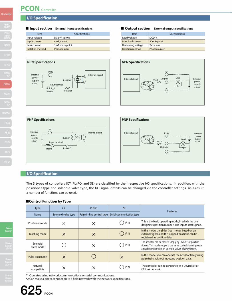
PCON Controller
625 PCON
PMECAMEC
Controller
Pulse Motor
Servo Motor (24V)
Servo Motor (200V)
LinearServo Motor
PSEP ASEPDSEP
MSEP
ERC3
ERC2
PCON-CA
PCON
ACON
SCON-CA
MSCON
PSEL
ASEL
SSEL
XSEL
PS-24
I/O Specification
I/O Specification
The 3 types of controllers (CY, PL/PO, and SE) are classified by their respective I/O specifications. In addition, with the positioner type and solenoid valve type, the I/O signal details can be changed via the controller settings. As a result, a number of functions can be used.
P24V
R=5.6kΩInputs
R=680Ω+24V
External power supply
Input terminal
Internal circuit
Input section External input specifications
P24
N
OutputsR=22ΩInternal circuit Load
+ 2 4 V
External power supply
N
R=5.6kΩInputs
R=680Ω+24V
External power supply
Input terminal
Internal circuit P24V
N
Outputs
Internal circuit
+ 2 4 V
External power supplyLoad
R=22Ω
Output section External output specifications
NPN Specifications NPN Specifications
PNP Specifications PNP Specifications
Control Function by Type
*1 Operates using network communications or serial communications. *2 Can make a direct connection to a field network with the network specifications.
Type CY PL/PO SEFeatures
Name Solenoid valve type Pulse in-line control type Serial communication type
Positioner mode × × (*1) This is the basic operating mode, in which the user designates position numbers and inputs start signals.
Teaching mode × × (*1)In this mode, the slider (rod) moves based on an external signal, and the stopped positions can be registered as position data.
Solenoid valve mode × (*1)
The actuator can be moved simply by ON/OFF of position signals. This mode supports the same control signals you are already familiar with on solenoid valves of air cylinders.
Pulse train mode × × In this mode, you can operate the actuator freely using pulse trains without inputting position data.
Network compatible × × (*2) The controller can be connected to a DeviceNet or
CC-Link network.
Item SpecificationsInput voltage DC24V ±10%Input current 4mA/circuitLeak current 1mA max./pointIsolation method Photocoupler
Item SpecificationsLoad Voltage DC24VMax. load current 50mA/pointRemaining voltage 2V or lessIsolation method Photocoupler
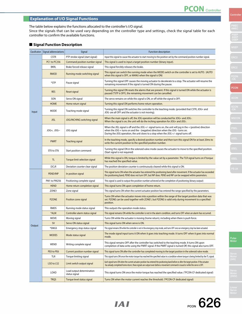
PCON Controller
PCON 626
PMECAMEC
Controller
Pulse Motor
Servo Motor (24V)
Servo Motor (200V)
LinearServo Motor
PSEP ASEPDSEP
MSEP
ERC3
ERC2
PCON-CA
PCON
ACON
SCON-CA
MSCON
PSEL
ASEL
SSEL
XSEL
PS-24
Explanation of I/O Signal Functions
The table below explains the functions allocated to the controller’s I/O signal. Since the signals that can be used vary depending on the controller type and settings, check the signal table for each controller to confirm the available functions.
(Note) Signals with asterisks (*) are normally ON and OFF during operation.
Signal Function Description
Classification Signal abbreviations Signal Function description
Input
CSTR PTP strobe signal (start signal) Input this signal to cause the actuator to start moving to the position set by the command position number signal.
PC1 to PC256 Command position number signal This signal is used to input a target position number (binary input).
BKRL Brake forced release signal This signal forcibly releases the brake.
RMOD Running mode switching signal This signal can switch the running mode when the MODE switch on the controller is set to AUTO. (AUTO when this signal is OFF, or MANU when the signal is ON)
*STP Pause signal Turning this signal OFF causes the moving actuator to decelerate to a stop. The actuator will resume the remaining movement if the signal is turned ON during the pause.
RES Reset signal Turning this signal ON resets the alarms that are present. If this signal is turned ON while the actuator is paused (*STP is OFF), the remaining movement can be cancelled.
SON Servo ON signal The servo remains on while this signal is ON, or off while the signal is OFF.
HOME Home return signal Turning this signal ON performs home-return operation.
MODE Teaching mode signal Turning this signal ON switches the controller to the teaching mode. (provided that CSTR, JOG+ and JOG- are all OFF and the actuator is not moving).
JISL JOG/INCHING switching signal When the main signal is off, the JOG operation will be conducted for JOG+ and JOG-.When the signal is on, the unit will do the inching operation for JOG+ and JOG-.
JOG+, JOG− JOG signalWhen the JISL signal is off and the JOG +/- signal turns on, the unit will jog in the + (positive) direction when the JOG + turns on and the - (negative) direction when the JOG - turns on.During the JOG operation, the unit slows to a stop when the JOG +/- signal turns off.
PWRT Teaching signal In the teaching mode, specify a desired position number and then turn this signal ON for at least 20ms to write the current position to the specified position number.
ST0 to ST6 Start position command Turning this signal ON in the solenoid valve mode causes the actuator to move to the specified position. (Start signal is not required)
TL Torque limit selection signal While this signal is ON, torque is limited by the value set by a parameter. The TLR signal turns on if torque has reached the specified value.
DCLR Deviation counter clear signal The position deviation counter is continuously cleared while this signal is ON.
Output
PEND/INP In position signal This signal turns ON when the actuator has entered the positioning band after movement. If the actuator has exceeded the positioning band, PEND does not turn OFF, but INP does. PEND and INP can be swapped within parameters.
PM1 to PM256 Positioning complete signal This signal is used to output the position number achieved at the completion of positioning (binary output)
HEND Home return completion signal This signal turns ON upon completion of home return.
ZONE1 Zone signal This signal turns ON when the current actuator position has entered the range specified by the parameters.
PZONE Position zone signalTurns ON when the actuator moves into a position within the range of the target position data that was set. PZONE can be used together with ZONE1, but PZONE is valid only during movement to a specified position.
RMDS Running mode status signal This outputs the operation mode status.
*ALM Controller alarm status signal This signal remains ON while the controller is not in the alarm condition, and turns OFF when an alarm has occurred.
MOVE Moving signal Turns ON while the actuator is moving (home return), including when there is push force.
SV Servo ON status signal This signal turns ON when servo is ON.
*EMGS Emergency stop status signal This signal remains ON while the controller is not in the emergency stop mode, and turns OFF once an emergency stop has been actuated.
MODES Mode status signal The mode signal input turns it ON when it goes into teaching mode. It turns OFF when it goes into normal mode.
WEND Writing complete signal This signal remains OFF after the controller has switched to the teaching mode. It turns ON upon completion of data write using the PWRT signal. If the PWRT signal is turned Off, this signal also turns OFF.
PE0 to PE6 Current position number signal This signal turns ON after the controller has completed moving to the target position in the solenoid valve mode.
TLR Torque limiting signal This signal turns ON once the motor torque has reached the specified value in a condition where torque is being limited by the TL signal.
LSO to LS2 Limit switch output signal Each signal turns ON when the current actuator position has entered the positioning band before or after the target position. If the actuator has already completed home return, these signals are output even before a movement command is issued or while the servo is OFF.
LOAD Load output determination status signal This signal turns ON once the motor torque has reached the specified value. (*PCON-CF dedicated signal)
TRQS Torque level status signal Turns ON when the motor current reaches the threshold. (*PCON-CF dedicated signal)
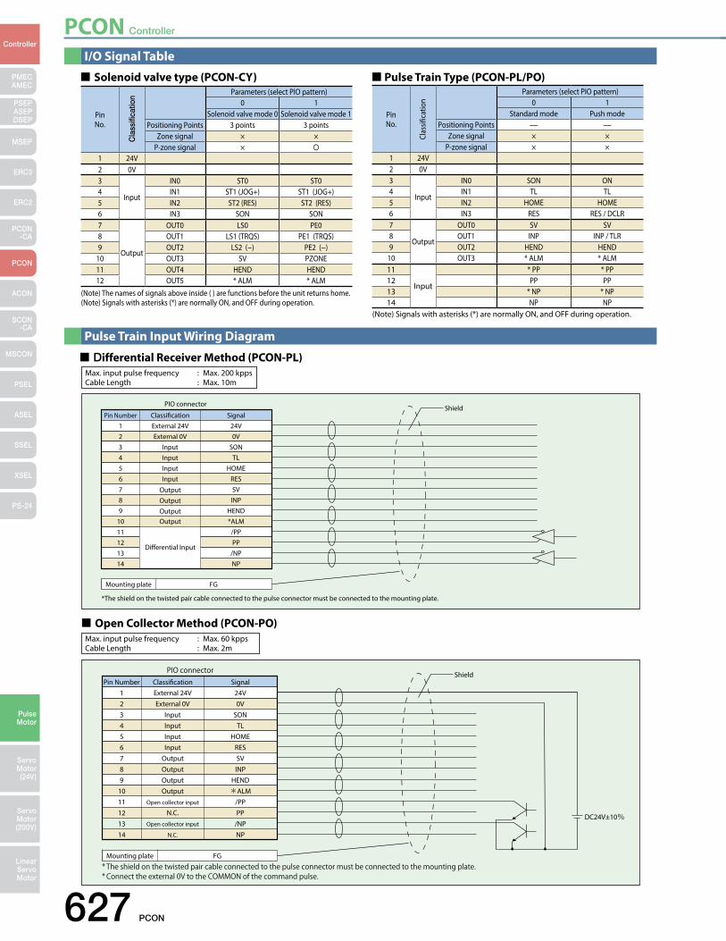
PCON Controller
627 PCON
PMECAMEC
Controller
Pulse Motor
Servo Motor (24V)
Servo Motor (200V)
LinearServo Motor
PSEP ASEPDSEP
MSEP
ERC3
ERC2
PCON-CA
PCON
ACON
SCON-CA
MSCON
PSEL
ASEL
SSEL
XSEL
PS-24
I/O Signal Table
Pulse Train Input Wiring Diagram
Solenoid valve type (PCON-CY)
(Note) The names of signals above inside ( ) are functions before the unit returns home.(Note) Signals with asterisks (*) are normally ON, and OFF during operation.
PinNo.
Parameters (select PIO pattern)0 1
Solenoid valve mode 0 Solenoid valve mode 1Positioning Points 3 points 3 points
Zone signal × ×P-zone signal ×
1 24V2 0V3
Input
IN0 ST0 ST04 IN1 ST1 (JOG+) ST1 (JOG+)5 IN2 ST2 (RES) ST2 (RES)6 IN3 SON SON7
Output
OUT0 LS0 PE08 OUT1 LS1 (TRQS) PE1 (TRQS)9 OUT2 LS2 (−) PE2 (−)
10 OUT3 SV PZONE11 OUT4 HEND HEND12 OUT5 * ALM * ALM
Cla
ssifi
catio
n
Pulse Train Type (PCON-PL/PO)
(Note) Signals with asterisks (*) are normally ON, and OFF during operation.
PinNo.
Parameters (select PIO pattern)0 1
Standard mode Push modePositioning Points — —
Zone signal × ×P-zone signal × ×
1 24V2 0V3
Input
IN0 SON ON4 IN1 TL TL5 IN2 HOME HOME6 IN3 RES RES / DCLR7
Output
OUT0 SV SV8 OUT1 INP INP / TLR9 OUT2 HEND HEND
10 OUT3 * ALM * ALM11
Input
* PP * PP12 PP PP13 * NP * NP14 NP NP
Clas
sific
atio
n
Differential Receiver Method (PCON-PL)Max. input pulse frequency : Max. 200 kppsCable Length : Max. 10m
Pin Number123456789
1011121314
External 24VExternal 0V
InputInputInputInput
OutputOutputOutputOutput
Dierential Input
24V0V
SONTL
HOMERESSVINP
HEND*ALM
/PPPP
/NPNP
Classication Signal
PIO connector Shield
Mounting plate FG
*The shield on the twisted pair cable connected to the pulse connector must be connected to the mounting plate.
Open Collector Method (PCON-PO)Max. input pulse frequency : Max. 60 kppsCable Length : Max. 2m
Pin Number123456789
1011121314
External 24VExternal 0V
InputInputInputInput
OutputOutputOutputOutput
Open collector input
N.C.Open collector input
N.C.
24V0V
SONTL
HOMERESSVINP
HEND*ALM
/PPPP
/NPNP
Classication Signal
PIO connector Shield
DC24V±10%
Mounting plate FG* The shield on the twisted pair cable connected to the pulse connector must be connected to the mounting plate.* Connect the external 0V to the COMMON of the command pulse.

PCON Controller
PCON 628
PMECAMEC
Controller
Pulse Motor
Servo Motor (24V)
Servo Motor (200V)
LinearServo Motor
PSEP ASEPDSEP
MSEP
ERC3
ERC2
PCON-CA
PCON
ACON
SCON-CA
MSCON
PSEL
ASEL
SSEL
XSEL
PS-24
Command Pulse Input State
Table Of Specifications
* The number of encoder pulse for the RCP3, RCP2 series operable with PCON is 800 in all models.
Item SpecificationsController type CY PL PO SE
Connected actuator (*1) RCP3/RCP2 series actuator (Note 1)
Number of control axes 1-axisOperating method Solenoid valve type Pulse train input type Serial communication type
Positioning Points 3 points — 64 pointsBackup memory EEPROMI/O connector 12-pin connector 14-pin connector NoneNumber of I/O 4 input points/6 output points 4 input points/4 output points NoneI/O power External supply DC24V±10% —Serial Communication RS485 1chPeripheral device communication cable CB-PACY-PIO CB-PACPU-PIO CB-RCB-CTL002Command pulse train input method — Differential line driver Open collector —Max. input pulse frequency (Note 2) — Max. 200 kpps Max. 60 kpps —Position detection method Incremental encoderDrive-source cutoff relay at emergency stop ExternalForced release of electromagnetic brake ON/OFF terminal signal inside the power terminal for brake releaseInput Supply Voltage DC 24 V ± 10%Power Supply Capacity 2A max.Dielectric strength voltage DC500V 1MΩ
Vibration resistance XYZ directions 10 to 57Hz, One side amplitude: 0.035mm (continuous), 0.075mm (intermittent) 58 to 150Hz, 4.9m/s2 (continuous), 9.8m/s2 (intermittent)
Ambient operating temperature 0~40°CAmbient operating humidity 10 - 95% (non-condensing)Ambient operating atmosphere Without corrosion gasesProtection class IP20Weight Approx. 130g
(Note 1) The high-thrust type (RA10C), high-speed type (HS8C/HS8R) and waterproof type (RCP2W-SA16) cannot be operated.(Note 2) With the open collector specification, keep the maximum input frequency to 60 kpps or below to prevent malfunction. For applications exceeding 60kpps, use the differential line driver.
Command pulse train state Input terminal During forward operation During reversed operation
Forward pulse train PP•/PP
Reversed pulse train NP•/NP
The forward pulse train causes the motor to rotate forward, and the reverse pulse train causes the motor to rotate in reverse.
Pulse train PP•/PP
Symbols NP•/NP
The command pulse is used for the amount of motor rotation, and the command symbol is used for rotational direction.
A/B phase pulse train
PP•/PP
NP•/NP
An A/B phase pulse with a 90° phase difference (multiplier is 4) is used to generate commands for the amount of rotation and rotational direction.
Forward pulse train PP•/PP
Reversed pulse train NP•/NP
Pulse train PP•/PP
Symbols NP•/NP
A/B phase pulse train
PP•/PP
NP•/NP
Neg
ativ
e lo
gic
Po
sitiv
e lo
gic
Low High
High Low
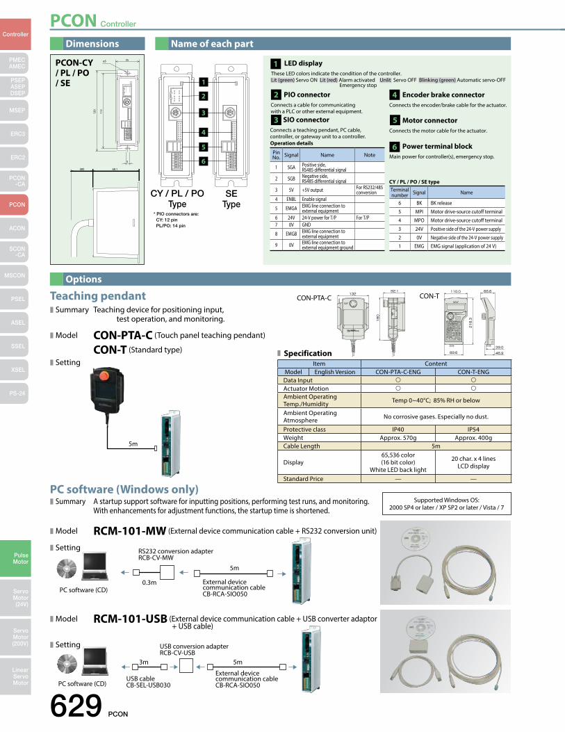
PCON Controller
629 PCON
PMECAMEC
Controller
Pulse Motor
Servo Motor (24V)
Servo Motor (200V)
LinearServo Motor
PSEP ASEPDSEP
MSEP
ERC3
ERC2
PCON-CA
PCON
ACON
SCON-CA
MSCON
PSEL
ASEL
SSEL
XSEL
PS-24
PC software (Windows only) Summary A startup support software for inputting positions, performing test runs, and monitoring. With enhancements for adjustment functions, the startup time is shortened.
Model RCM-101-MW (External device communication cable + RS232 conversion unit)
Setting
Model RCM-101-USB (External device communication cable + USB converter adaptor + USB cable)
Setting
Supported Windows OS: 2000 SP4 or later / XP SP2 or later / Vista / 7
CON-PTA-C CON-T
Options
Dimensions
120
112
35
5
ø5
68.1(80)
PCON-CY/ PL / PO / SE
* PIO connectors are: CY: 12 pin PL/PO: 14 pin
CY / PL / POType
SEType
1
3
4
5
6
2
Terminal number Signal Name
6 BK BK release
5 MPI Motor drive-source cutoff terminal
4 MPO Motor drive-source cutoff terminal
3 24V Positive side of the 24-V power supply
2 0V Negative side of the 24-V power supply
1 EMG EMG signal (application of 24 V)
CY / PL / PO / SE type
PIO connector Connects a cable for communicating with a PLC or other external equipment.
2
SIO connectorConnects a teaching pendant, PC cable, controller, or gateway unit to a controller.
3
Pin No. Signal Name Note
1 SGA Positive side, RS485 differential signal
2 SGB Negative side, RS485 differential signal
3 5V +5V output For RS232/485 conversion
4 ENBL Enable signal
5 EMGA EMG line connection to external equipment
6 24V 24-V power for T/P For T/P7 0V GND
8 EMGB EMG line connection to external equipment
9 0V EMG line connection to external equipment ground
Operation details
Name of each part
Encoder brake connectorConnects the encoder/brake cable for the actuator.
4
Motor connectorConnects the motor cable for the actuator.
5
Power terminal blockMain power for controller(s), emergency stop.
6
LED display These LED colors indicate the condition of the controller. Lit (green) Servo ON Lit (red) Alarm activated Unlit Servo OFF Blinking (green) Automatic servo-OFF
Emergency stop
1
Item ContentModel English Version CON-PTA-C-ENG CON-T-ENG
Data Input Actuator Motion Ambient Operating Temp./Humidity Temp 0~40°C; 85% RH or below
Ambient Operating Atmosphere No corrosive gases. Especially no dust.
Protective class IP40 IP54Weight Approx. 570g Approx. 400gCable Length 5m
Display65,536 color(16 bit color)
White LED back light
20 char. x 4 lines LCD display
Standard Price — —
Specification
RS232 conversion adapter RCB-CV-MW
External device communication cable CB-RCA-SIO050
0.3m
5m
PC software (CD)
Teaching pendantSummary Teaching device for positioning input, test operation, and monitoring.
Model CON-PTA-C (Touch panel teaching pendant)
CON-T (Standard type)
Setting
5m
External device communication cable CB-RCA-SIO050
USB conversion adapter RCB-CV-USB
USB cable CB-SEL-USB030
3m 5m
PC software (CD)
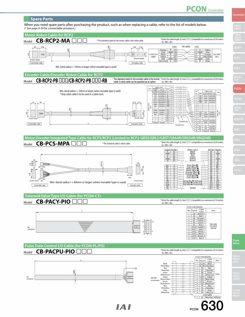
PCON Controller
PCON 630
PMECAMEC
Controller
Pulse Motor
Servo Motor (24V)
Servo Motor (200V)
LinearServo Motor
PSEP ASEPDSEP
MSEP
ERC3
ERC2
PCON-CA
PCON
ACON
SCON-CA
MSCON
PSEL
ASEL
SSEL
XSEL
PS-24
Spare PartsWhen you need spare parts after purchasing the product, such as when replacing a cable, refer to the list of models below.(* See page A-59 for connectable actuators.)
* Enter the cable length (L) into. Compatible to a maximum of 20 meters. Ex.: 080 = 8m
PHD
R-16
VS(J
ST)
XMP-
18V
(JST
)
Blue (Red 1)
C N 4
CN2Cable color
SignalPinNo.
Brown Light Gray (Black 1)
Orange (Black 2)
1
—
FG
ENA
ENAENA
ENAENBENB
ENBENB
VPSVBB
GNDVBBVPS
LS+
LS+
BK+
BK+
BK−
BK−
FG
LS−
LS−
GND(NC)(NC)(NC)
16
Shielded wire
Ground wire
Cable color Standard
Cable Robot Cable
Standard Cable Robot CableSignalPinNo.
L
CN2
CN4
(5) (8) (13) (15)
(18)
(Front view)
(ø9)
(35)
(25)
(Front view)
Actuator sideController side
WhiteRedGray
BrownGreenPurple
Pink—
YellowOrange
Blue———
———
— — —
— — —
— — —— — —— — —— — —
Ground
Orange (Red 2)Orange (Black 1)Orange (Red 1)
Light Gray (Black 1)Light Gray (Red 1)
White (Black 1)White (Red 1)
—Yellow (Black 1)Pink (Red 1)
Pink (Black 1)
Ground
151413121110987654321
23456789
101112131415161718
GreenPurple
Pink
BlueOrangeYellow
Blue (Red 1)White
RedGray
Ground
Light Gray (Red 1)White (Black 1)White (Red 1)
Pink (Black 1)Pink (Red 1)
Yellow (Black 1)
Orange (Black 2)Orange (Red 2)
Orange (Black 1)Orange (Red 1)
Ground
Model CB-RCP2-PB /CB-RCP2-PB -RBEncoder Cable/Encoder Robot Cable for RCP2
* The standard cable for the encoder cable is the normal cable. A robot cable can be specified as an option.
Min. bend radius r = 54mm or larger (when movable type is used)* Only robot cable is to be used in a cable track.
A A
I-1318119-3(AMP)
SLP-06V(JST)
M cableCN3 CN1Orange YellowA1 1
(20)(8)
(Front view)
(15)
L
CN3CN1
(ø8)
(28) (14)
(14)
(20)
(Front view)
Controller side
GrayWhiteYellow
PinkYellow (Green)
VMMBA
VMMB
A2A3B1B2B3
23456
VMMAB
VMMB
GrayOrange
Yellow (Green)Pink
WhiteActuator side
Model CB-RCP2-MA Motor Robot Cable for RCP2
* Enter the cable length (L) into. Compatible to a maximum of 20 meters. Ex.: 080 = 8m* The standard cable for the motor cable is the robot cable.
Min. bend radius r = 50mm or larger (when movable type is used)
* Enter the cable length (L) into. Compatible to a maximum of 10 meters. Ex.: 080 = 8m
1
1112
2
(crimped)AWG28
Flat cable
51353-1200 (MOLEX)
No connector
LBrown-1
CableColorNo. Signal Wire
24V123456789
101112
0VIN0IN1IN2IN3
OUT0OUT1OUT2OUT3OUT4OUT5
Red-1Orange-1Yellow-1Green-1Blue-1
Purple-1Gray-1
White-1Black-1
Brown-2Red-2
Model CB-PACY-PIO Solenoid Valve Type I/O Cable (for PCON-CY)
* Enter the cable length (L) into. Compatible to a maximum of 10 meters. Ex.: 080 = 8m
0.2sq
51353-1400 (MOLEX)
No connector Side with
no connector
0.5-5 (JST)White/Gray
(ø9)
L
BlackBlack
CableColorNo. Signal Wire
IO_24V
FG
1
1 AWG24
White/BlackRed
White/RedGreen
White/GreenYellow
White/YellowBrown
White/BrownBlue
White/BlueGray
White/Gray
23456789
1011121314
IO_24GIN0IN1IN2IN3
OUT0OUT1OUT2OUT3
PPPGNPNG
White/BlackRed
White/RedGreen
White/GreenYellow
White/YellowBrown
White/BrownBlue
White/BlueGray
White/Gray
Model CB-PACPU-PIO Pulse Train Control I/O Cable (for PCON-PL/PO)
* Enter the cable length (L) into. Compatible to a maximum of 20 meters. Ex.: 080 = 8m
L
(15)
(ø10
.5)
A
Pink (Red )Pink (Blue )
White (Red )White (Blue )Orange (Red )Orange (Blue )
Gray (Red )Gray (Blue )
Orange (Blue Continuous)Gray (Red Continuous)Gray (Blue Continuous)
Shield
BlackB1 A1 A
BK+ 14
(18)
(8)
(20)
(8)
(5)
(30)
(18)
(23)
Signal Pin No. (Wire color) Pin No. Signal
Controller side Actuator side
(Front view) (Front view)
BK−LS+LS−A+A−B+B−NCVPSVCCGNDNCFG
VMM/AB
VMM/B
A2A1B3B2A3
1316151211109876541
WhiteRed
GreenYellowBrown
B1A2B2A3B3A4B4A5B5A6B6A7B7A8B8A9B9
A10B10A11B11
VMM/AB
VMM/BNCNC
BK+BK−LS+LS−A+A−B+B−NCVPSVCCGNDNCFG
Model CB-PCS-MPA Motor-Encoder Integrated Type Cable for RCP3/RCP2 (Limited to RCP2-GRSS/GRLS/GRST/SRA4R/SRGS4R/SRGD4R)
* The standard cable is robot cable.
Min. bend radius r = 84mm or larger (when movable type is used)
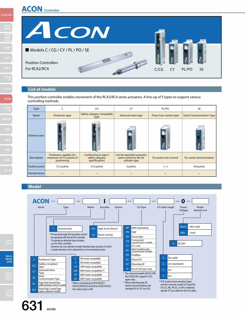
ACON Controller
631 ACON
PMECAMEC
Controller
Pulse Motor
Servo Motor (24V)
Servo Motor (200V)
LinearServo Motor
PSEP ASEPDSEP
MSEP
ERC3
ERC2
PCON-CA
PCON
ACON
SCON-CA
MSCON
PSEL
ASEL
SSEL
XSEL
PS-24
List of models
This position controller enables movement of the RCA2/RCA series actuators. A line-up of 5 types to support various controlling methods.
ACON 0Series Type Motor Encoder Option I/O Type I/O Cable Length Power
Voltage
C Positioner Type
CGSafety-compliant type
CY Solenoid Valve Type
SESerial Communication Type
PL Pulse Train Control Type(dierential line driver model)
PO Pulse Train Control Type(open collector model)
I Incremental
0 DC24V
0 No cable
2 2m (standard)
3 3m
5 5m
I
20S 20W motor-compatible (*)
10
5
10W motor-compatible
2 2W motor-compatible
5W motor-compatible
20 20W motor-compatible
30 30W motor-compatible
* When connecting an RCA-RA3/ RGS3/RGD3 and RCA2-SA4/TA5, the motor type is 20S.
* The absolute-type RCA actuators cannot be operated with the ACON controller To operate an absolute-type actuator, use the ASEL controller. However, you can operate a simple absolute-type actuator, in which a simple absolute unit is attached to an incremental actuator.
* The network models (DV/CC/PR/ ML/CN/EC/EP) support C/CG types only.* When selecting type SE (serial communication), the standard I/O is "N" (no I/O).
NP NPN (standard)
PN PNP
PR ProBus
EC EtherCAT
EP EtherNet/IP
ML MECHATROLINK connection model
CN CompoNet connection model
CC CC-Link
DV DeviceNet
No I/O (SE type only)N
HA High Accel./Decel.
LA Power-saving
Simple absolute unit
Blank Not used
ABU Used
* If SE (serial communication type), and the network model (I/O type DV, CN, CC, ML, PR, EC, or EP) is selected, specify "0" (no cable) for the I/O cable.
Model
Position ControllersFor RCA2/RCA C/CG CY PL/PO SE
Models C / CG / CY / PL / PO / SE
Type C CG CY PL/PO SE
Name Positioner type Safety category compatible type Solenoid valve type Pulse train control type Serial Communication Type
External view
DescriptionPositioner capable of a
maximum of 512 points of positioning
Conforming to type C safety category specifications
Can be operated using the same control as the air
cylinder typeFor pulse train control For serial communication
Position points 512 points 512 points 3 points (—) 64 points
Standard price — — — — —
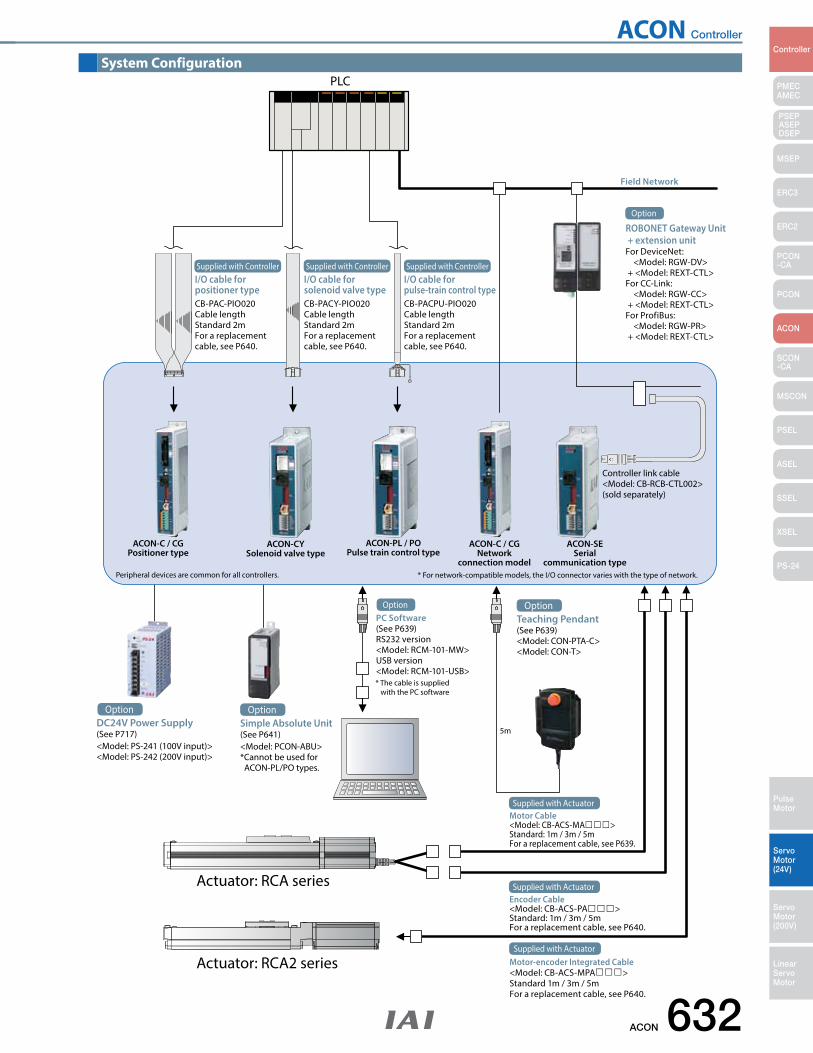
ACON Controller
ACON 632
PMECAMEC
Controller
Pulse Motor
Servo Motor (24V)
Servo Motor (200V)
LinearServo Motor
PSEP ASEPDSEP
MSEP
ERC3
ERC2
PCON-CA
PCON
ACON
SCON-CA
MSCON
PSEL
ASEL
SSEL
XSEL
PS-24
PLC
5m
Field Network
ROBONET Gateway Unit + extension unitFor DeviceNet: <Model: RGW-DV> + <Model: REXT-CTL>For CC-Link: <Model: RGW-CC> + <Model: REXT-CTL>For ProfiBus: <Model: RGW-PR> + <Model: REXT-CTL>
Option
OptionPC Software(See P639)RS232 version<Model: RCM-101-MW>USB version<Model: RCM-101-USB>* The cable is supplied with the PC software
Teaching Pendant(See P639)<Model: CON-PTA-C><Model: CON-T>
Option
DC24V Power Supply(See P717)<Model: PS-241 (100V input)><Model: PS-242 (200V input)>
OptionSimple Absolute Unit(See P641)<Model: PCON-ABU>*Cannot be used for ACON-PL/PO types.
Option
Motor Cable<Model: CB-ACS-MA>Standard: 1m / 3m / 5mFor a replacement cable, see P639.
Supplied with Actuator
Encoder Cable<Model: CB-ACS-PA>Standard: 1m / 3m / 5mFor a replacement cable, see P640.
Supplied with Actuator
Motor-encoder Integrated Cable<Model: CB-ACS-MPA>Standard 1m / 3m / 5mFor a replacement cable, see P640.
Supplied with Actuator
ACON-C / CGPositioner type
ACON-CYSolenoid valve type
ACON-PL / POPulse train control type
ACON-C / CGNetwork
connection model
ACON-SESerial
communication type* For network-compatible models, the I/O connector varies with the type of network.Peripheral devices are common for all controllers.
Actuator: RCA series
Actuator: RCA2 series
Controller link cable<Model: CB-RCB-CTL002>(sold separately)
I/O cable for positioner typeCB-PAC-PIO020Cable lengthStandard 2mFor a replacement cable, see P640.
Supplied with ControllerI/O cable for solenoid valve typeCB-PACY-PIO020Cable lengthStandard 2mFor a replacement cable, see P640.
Supplied with ControllerI/O cable for pulse-train control typeCB-PACPU-PIO020Cable lengthStandard 2mFor a replacement cable, see P640.
Supplied with Controller
System Configuration
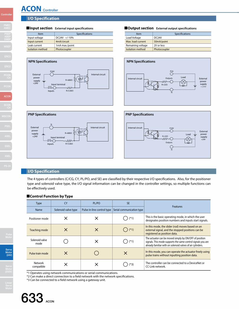
ACON Controller
633 ACON
PMECAMEC
Controller
Pulse Motor
Servo Motor (24V)
Servo Motor (200V)
LinearServo Motor
PSEP ASEPDSEP
MSEP
ERC3
ERC2
PCON-CA
PCON
ACON
SCON-CA
MSCON
PSEL
ASEL
SSEL
XSEL
PS-24
I/O Specification
I/O Specification
Input section External input specifications Output section External output specifications
Control Function by Type
*1 Operates using network communications or serial communications. *2 Can make a direct connection to a field network with the network specifications.*3 Can be connected to a field network using a gateway unit.
Type CY PL/PO SEFeatures
Name Solenoid valve type Pulse in-line control type Serial communication type
Positioner mode (*1) This is the basic operating mode, in which the user designates position numbers and inputs start signals.
Teaching mode (*1)In this mode, the slider (rod) moves based on an external signal, and the stopped positions can be registered as position data.
Solenoid valve mode (*1)
The actuator can be moved simply by ON/OFF of position signals. This mode supports the same control signals you are already familiar with on solenoid valves of air cylinders.
Pulse train mode In this mode, you can operate the actuator freely using pulse trains without inputting position data.
Network compatible (*3) The controller can be connected to a DeviceNet or
CC-Link network.
Item SpecificationsInput voltage DC24V +/-10%Input current 4mA/circuitLeak current 1mA max./pointIsolation method Photocoupler
Item SpecificationsLoad Voltage DC24VMax. load current 50mA/pointRemaining voltage 2V or lessIsolation method Photocoupler
The 4 types of controllers (C/CG, CY, PL/PO, and SE) are classified by their respective I/O specifications. Also, for the positioner type and solenoid valve type, the I/O signal information can be changed in the controller settings, so multiple functions can be effectively used.
P24V
R=5.6kΩInputs
R=680Ω
+24V
External power supply
Input terminal
Internal circuit
NPN Specifications
P24
N
OutputsInternal circuit Load
+ 2 4 V
External power supplyR=22Ω
NPN Specifications
N
R=5.6kΩInputs
R=680Ω
+24V
External power supply
Input terminal
Internal circuit
PNP Specifications
P24V
N
Outputs
Internal circuit
+24V
External power supply
LoadR=22Ω
PNP Specifications
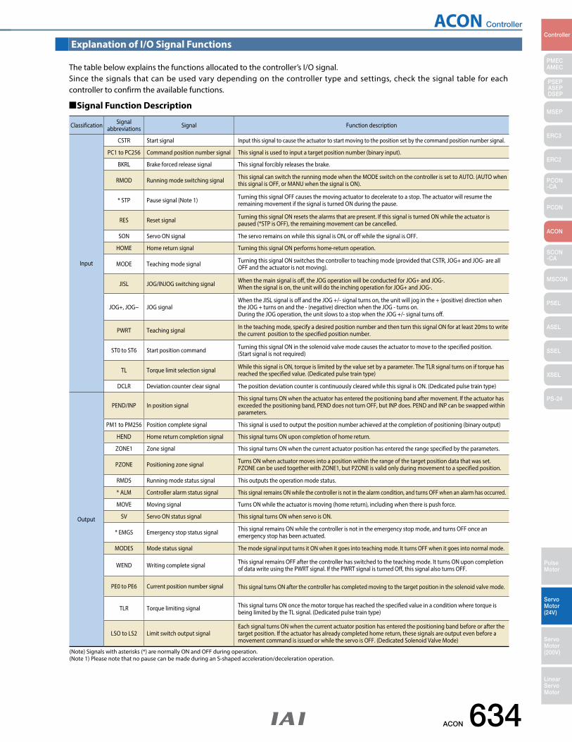
ACON Controller
ACON 634
PMECAMEC
Controller
Pulse Motor
Servo Motor (24V)
Servo Motor (200V)
LinearServo Motor
PSEP ASEPDSEP
MSEP
ERC3
ERC2
PCON-CA
PCON
ACON
SCON-CA
MSCON
PSEL
ASEL
SSEL
XSEL
PS-24
Explanation of I/O Signal Functions
The table below explains the functions allocated to the controller’s I/O signal. Since the signals that can be used vary depending on the controller type and settings, check the signal table for each controller to confirm the available functions.
Signal Function Description
(Note) Signals with asterisks (*) are normally ON and OFF during operation.(Note 1) Please note that no pause can be made during an S-shaped acceleration/deceleration operation.
Classification Signal abbreviations Signal Function description
Input
CSTR Start signal Input this signal to cause the actuator to start moving to the position set by the command position number signal.
PC1 to PC256 Command position number signal This signal is used to input a target position number (binary input).
BKRL Brake forced release signal This signal forcibly releases the brake.
RMOD Running mode switching signal This signal can switch the running mode when the MODE switch on the controller is set to AUTO. (AUTO when this signal is OFF, or MANU when the signal is ON).
* STP Pause signal (Note 1) Turning this signal OFF causes the moving actuator to decelerate to a stop. The actuator will resume the remaining movement if the signal is turned ON during the pause.
RES Reset signal Turning this signal ON resets the alarms that are present. If this signal is turned ON while the actuator is paused (*STP is OFF), the remaining movement can be cancelled.
SON Servo ON signal The servo remains on while this signal is ON, or off while the signal is OFF.
HOME Home return signal Turning this signal ON performs home-return operation.
MODE Teaching mode signal Turning this signal ON switches the controller to teaching mode (provided that CSTR, JOG+ and JOG- are all OFF and the actuator is not moving).
JISL JOG/INJOG switching signal When the main signal is off, the JOG operation will be conducted for JOG+ and JOG-.When the signal is on, the unit will do the inching operation for JOG+ and JOG-.
JOG+, JOG− JOG signalWhen the JISL signal is off and the JOG +/- signal turns on, the unit will jog in the + (positive) direction when the JOG + turns on and the - (negative) direction when the JOG - turns on.During the JOG operation, the unit slows to a stop when the JOG +/- signal turns off.
PWRT Teaching signal In the teaching mode, specify a desired position number and then turn this signal ON for at least 20ms to write the current position to the specified position number.
ST0 to ST6 Start position command Turning this signal ON in the solenoid valve mode causes the actuator to move to the specified position.(Start signal is not required)
TL Torque limit selection signal While this signal is ON, torque is limited by the value set by a parameter. The TLR signal turns on if torque has reached the specified value. (Dedicated pulse train type)
DCLR Deviation counter clear signal The position deviation counter is continuously cleared while this signal is ON. (Dedicated pulse train type)
Output
PEND/INP In position signalThis signal turns ON when the actuator has entered the positioning band after movement. If the actuator has exceeded the positioning band, PEND does not turn OFF, but INP does. PEND and INP can be swapped within parameters.
PM1 to PM256 Position complete signal This signal is used to output the position number achieved at the completion of positioning (binary output)
HEND Home return completion signal This signal turns ON upon completion of home return.
ZONE1 Zone signal This signal turns ON when the current actuator position has entered the range specified by the parameters.
PZONE Positioning zone signal Turns ON when actuator moves into a position within the range of the target position data that was set. PZONE can be used together with ZONE1, but PZONE is valid only during movement to a specified position.
RMDS Running mode status signal This outputs the operation mode status.
* ALM Controller alarm status signal This signal remains ON while the controller is not in the alarm condition, and turns OFF when an alarm has occurred.
MOVE Moving signal Turns ON while the actuator is moving (home return), including when there is push force.
SV Servo ON status signal This signal turns ON when servo is ON.
* EMGS Emergency stop status signal This signal remains ON while the controller is not in the emergency stop mode, and turns OFF once an emergency stop has been actuated.
MODES Mode status signal The mode signal input turns it ON when it goes into teaching mode. It turns OFF when it goes into normal mode.
WEND Writing complete signal This signal remains OFF after the controller has switched to the teaching mode. It turns ON upon completion of data write using the PWRT signal. If the PWRT signal is turned Off, this signal also turns OFF.
PE0 to PE6 Current position number signal This signal turns ON after the controller has completed moving to the target position in the solenoid valve mode.
TLR Torque limiting signal This signal turns ON once the motor torque has reached the specified value in a condition where torque is being limited by the TL signal. (Dedicated pulse train type)
LSO to LS2 Limit switch output signalEach signal turns ON when the current actuator position has entered the positioning band before or after the target position. If the actuator has already completed home return, these signals are output even before a movement command is issued or while the servo is OFF. (Dedicated Solenoid Valve Mode)
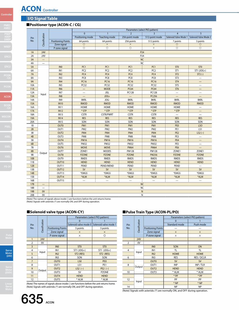
ACON Controller
635 ACON
PMECAMEC
Controller
Pulse Motor
Servo Motor (24V)
Servo Motor (200V)
LinearServo Motor
PSEP ASEPDSEP
MSEP
ERC3
ERC2
PCON-CA
PCON
ACON
SCON-CA
MSCON
PSEL
ASEL
SSEL
XSEL
PS-24
I/O Signal TablePositioner type (ACON-C / CG)
(Note) The names of signals above inside ( ) are functions before the unit returns home.(Note) Signals with asterisks (*) are normally ON, and OFF during operation.
PinNo.
Parameters (select PIO pattern)0 1 2 3 4 5
Positioning mode Teaching mode 256-point mode 512-point mode Solenoid Valve Mode 1 Solenoid Valve Mode 2Positioning Points 64 points 64 points 256 points 512 points 7 points 3 points
Zone signal
P-zone signal
1A 24V P242A 24V P243A — NC4A — NC5A
Input
IN0 PC1 PC1 PC1 PC1 ST0 ST06A IN1 PC2 PC2 PC2 PC2 ST1 ST1 (JOG+)7A IN2 PC4 PC4 PC4 PC4 ST2 ST2 (-)8A IN3 PC8 PC8 PC8 PC8 ST3 —9A IN4 PC16 PC16 PC16 PC16 ST4 —
10A IN5 PC32 PC32 PC32 PC32 ST5 —11A IN6 — MODE PC64 PC64 ST6 —12A IN7 — JISL PC128 PC128 — —13A IN8 — JOG+ — PC256 — —14A IN9 BKRL JOG- BKRL BKRL BKRL BKRL15A IN10 RMOD RMOD RMOD RMOD RMOD RMOD16A IN11 HOME HOME HOME HOME HOME —17A IN12 * STP * STP * STP * STP * STP —18A IN13 CSTR CSTR/PWRT CSTR CSTR — —19A IN14 RES RES RES RES RES RES20A IN15 SON SON SON SON SON SON1B
Output
OUT0 PM1 PM1 PM1 PM1 PE0 LSO2B OUT1 PM2 PM2 PM2 PM2 PE1 LS13B OUT2 PM4 PM4 PM4 PM4 PE2 LS2 (−)4B OUT3 PM8 PM8 PM8 PM8 PE3 —5B OUT4 PM16 PM16 PM16 PM16 PE4 —6B OUT5 PM32 PM32 PM32 PM32 PE5 —7B OUT6 MOVE MOVE PM64 PM64 PE6 —8B OUT7 ZONE1 MODES PM128 PM128 ZONE1 ZONE19B OUT8 PZONE PZONE PZONE PM256 PZONE PZONE
10B OUT9 RMDS RMDS RMDS RMDS RMDS RMDS11B OUT10 HEND HEND HEND HEND HEND HEND12B OUT11 PEND PEND/WEND PEND PEND PEND —13B OUT12 SV SV SV SV SV SV14B OUT13 *EMGS *EMGS *EMGS *EMGS *EMGS *EMGS15B OUT14 *ALM *ALM *ALM *ALM *ALM *ALM16B OUT15 — — — — — —17B — NC18B — NC19B 0V N20B 0V N
Clas
sific
atio
n
Solenoid valve type (ACON-CY)
(Note) The names of signals above inside ( ) are functions before the unit returns home.(Note) Signals with asterisks (*) are normally ON, and OFF during operation.
PinNo.
Parameters (select PIO pattern)0 1
Solenoid valve mode 0 Solenoid valve mode 1Positioning Points 3 points 3 points
Zone signal × ×P-zone signal ×
1 24V2 0V3
Input
IN0 ST0 ST04 IN1 ST1 (JOG+) ST1 (JOG+)5 IN2 ST2 (RES) ST2 (RES)6 IN3 SON SON7
Output
OUT0 LS0 PE08 OUT1 LS1 PE19 OUT2 LS2 (−) PE2 (−)
10 OUT3 SV PZONE11 OUT4 HEND HEND12 OUT5 * ALM * ALM
Clas
sific
atio
n
Pulse Train Type (ACON-PL/PO)
(Note) Signals with asterisks (*) are normally ON, and OFF during operation.
PinNo.
Parameters (select PIO pattern)0 1
Standard mode Push modePositioning Points — —
Zone signal × ×P-zone signal × ×
24V2 0V
Input
IN0 SON ON4 IN1 TL TL
IN2 HOME HOME6 IN3 RES RES / DCLR
Output
OUT0 SV SV8 OUT1 INP INP / TLR
OUT2 HEND HEND10 OUT3 * ALM * ALM
Input
* PP * PP12 PP PP
* NP * NP14 NP NP
Clas
sific
atio
n
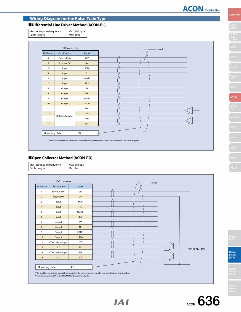
ACON Controller
ACON 636
PMECAMEC
Controller
Pulse Motor
Servo Motor (24V)
Servo Motor (200V)
LinearServo Motor
PSEP ASEPDSEP
MSEP
ERC3
ERC2
PCON-CA
PCON
ACON
SCON-CA
MSCON
PSEL
ASEL
SSEL
XSEL
PS-24
Pin Number
1 External 24V 24V
Dierential input
Classication Signal
PIO connector Shield
Mounting plate FG
* The shield on the twisted pair cable connected to the pulse connector must be connected to the mounting plate.
2
3
4
5
6
7
8
9
10
11
12
13
14
External 0V
Input
Input
Input
Input
Output
Output
Output
Output
0V
SON
TL
HOME
RES
SV
INP
HEND
* ALM
/PP
PP
/NP
NP
Pin Number
1 External 24V 24V
Classication Signal
PIO connector Shield
DC24V±10%
Mounting plate FG
* The shield on the twisted pair cable connected to the pulse connector must be connected to the mounting plate. * Connect the external 0V to the COMMON of the command pulse.
External 0V
Input
Input
Input
Input
Output
Output
Output
Output
Open collector input
N.C
Open collector input
N.C
0V
SON
TL
HOME
RES
SV
INP
HEND
* ALM
/PP
PP
/NP
NP
2
3
4
5
6
7
8
9
10
11
12
13
14
Wiring Diagram for the Pulse-Train TypeDifferential Line Driver Method (ACON-PL)
Open Collector Method (ACON-PO)
Max. input pulse frequency : Max. 200 kppsCable Length : Max. 10m
Max. input pulse frequency : Max. 60 kppsCable Length : Max. 2m
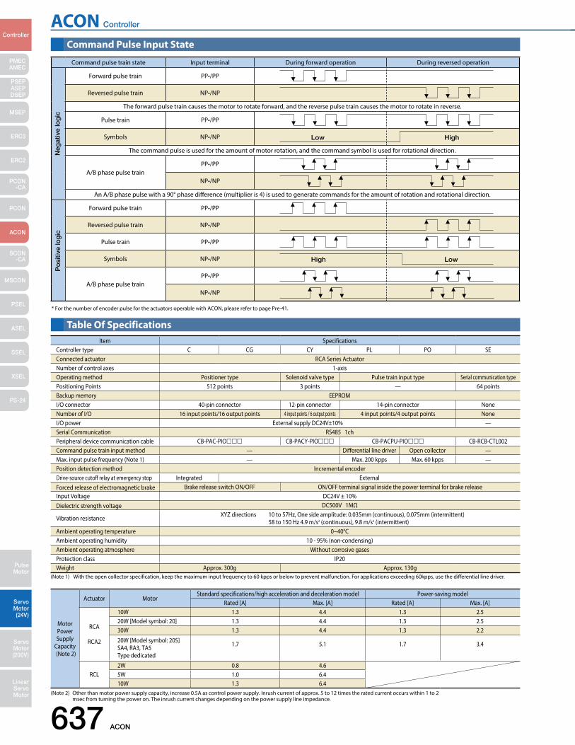
ACON Controller
637 ACON
PMECAMEC
Controller
Pulse Motor
Servo Motor (24V)
Servo Motor (200V)
LinearServo Motor
PSEP ASEPDSEP
MSEP
ERC3
ERC2
PCON-CA
PCON
ACON
SCON-CA
MSCON
PSEL
ASEL
SSEL
XSEL
PS-24
Command Pulse Input State
Table Of Specifications
* For the number of encoder pulse for the actuators operable with ACON, please refer to page Pre-41.
(Note 1) With the open collector specification, keep the maximum input frequency to 60 kpps or below to prevent malfunction. For applications exceeding 60kpps, use the differential line driver.
Item SpecificationsController type C CG CY PL PO SEConnected actuator RCA Series ActuatorNumber of control axes 1-axisOperating method Positioner type Solenoid valve type Pulse train input type Serial communication typePositioning Points 512 points 3 points — 64 pointsBackup memory EEPROMI/O connector 40-pin connector 12-pin connector 14-pin connector NoneNumber of I/O 16 input points/16 output points 4 input points / 6 output points 4 input points/4 output points NoneI/O power External supply DC24V±10% —Serial Communication RS485 1chPeripheral device communication cable CB-PAC-PIO CB-PACY-PIO CB-PACPU-PIO CB-RCB-CTL002Command pulse train input method — Differential line driver Open collector —Max. input pulse frequency (Note 1) — Max. 200 kpps Max. 60 kpps —Position detection method Incremental encoderDrive-source cutoff relay at emergency stop Integrated ExternalForced release of electromagnetic brake Brake release switch ON/OFF ON/OFF terminal signal inside the power terminal for brake releaseInput Voltage DC24V ± 10%Dielectric strength voltage DC500V 1MΩ
Vibration resistance XYZ directions 10 to 57Hz, One side amplitude: 0.035mm (continuous), 0.075mm (intermittent) 58 to 150 Hz 4.9 m/s2 (continuous), 9.8 m/s2 (intermittent)
Ambient operating temperature 0~40°CAmbient operating humidity 10 - 95% (non-condensing)Ambient operating atmosphere Without corrosive gasesProtection class IP20Weight Approx. 300g Approx. 130g
(Note 2) Other than motor power supply capacity, increase 0.5A as control power supply. Inrush current of approx. 5 to 12 times the rated current occurs within 1 to 2 msec from turning the power on. The inrush current changes depending on the power supply line impedance.
Motor Power Supply
Capacity(Note 2)
Actuator MotorStandard specifications/high acceleration and deceleration model Power-saving model
Rated [A] Max. [A] Rated [A] Max. [A]
RCA
RCA2
10W 1.3 4.4 1.3 2.520W [Model symbol: 20] 1.3 4.4 1.3 2.530W 1.3 4.4 1.3 2.2
20W [Model symbol: 20S] SA4, RA3, TA5Type dedicated
1.7 5.1 1.7 3.4
RCL2W 0.8 4.65W 1.0 6.410W 1.3 6.4
Command pulse train state Input terminal During forward operation During reversed operation
Forward pulse train PP•/PP
Reversed pulse train NP•/NP
The forward pulse train causes the motor to rotate forward, and the reverse pulse train causes the motor to rotate in reverse.
Pulse train PP•/PP
Symbols NP•/NP
The command pulse is used for the amount of motor rotation, and the command symbol is used for rotational direction.
A/B phase pulse trainPP•/PP
NP•/NP
An A/B phase pulse with a 90° phase difference (multiplier is 4) is used to generate commands for the amount of rotation and rotational direction.
Forward pulse train PP•/PP
Reversed pulse train NP•/NP
Pulse train PP•/PP
Symbols NP•/NP
A/B phase pulse trainPP•/PP
NP•/NP
Neg
ativ
e lo
gic
Po
sitiv
e lo
gic
Low High
High Low
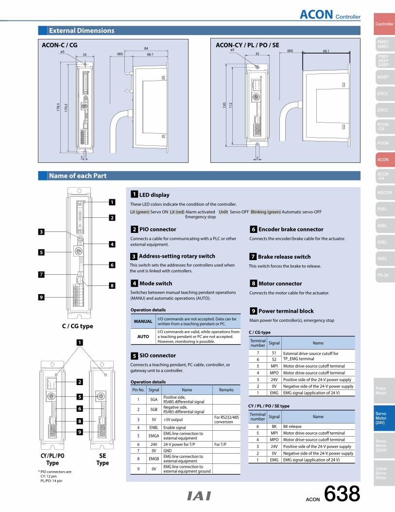
ACON Controller
ACON 638
PMECAMEC
Controller
Pulse Motor
Servo Motor (24V)
Servo Motor (200V)
LinearServo Motor
PSEP ASEPDSEP
MSEP
ERC3
ERC2
PCON-CA
PCON
ACON
SCON-CA
MSCON
PSEL
ASEL
SSEL
XSEL
PS-24
External Dimensions
Name of each Part
5
170.
5
178.
5
ø535 (80)
84
68.1
68.1
170.
5
178.
5
ø584
68.1
5
ACON-C / CG
120
112
35
5
ø5 68.1
68.1
120
112
5
35ø5 (80)
1
2
3
4
5
6
7
8
C / CG type
9
* PIO connectors are: CY: 12 pin PL/PO: 14 pin
1
CY / PL / POType
SEType
5
6
8
9
2
Terminal number Signal Name
7 S1 External drive-source cutoff for TP_EMG terminal6 S2
5 MPI Motor drive-source cutoff terminal
4 MPO Motor drive-source cutoff terminal
3 24V Positive side of the 24-V power supply2 0V Negative side of the 24-V power supply1 EMG EMG signal (application of 24 V)
C / CG type
Pin No. Signal Name Remarks
1 SGA Positive side, RS485 differential signal
2 SGB Negative side, RS485 differential signal
3 5V +5V output For RS232/485 conversion
4 ENBL Enable signal
5 EMGA EMG line connection to external equipment
6 24V 24-V power for T/P For T/P7 0V GND
8 EMGB EMG line connection to external equipment
9 0V EMG line connection to external equipment ground
Operation details
MANUAL I/O commands are not accepted. Data can be written from a teaching pendant or PC.
AUTOI/O commands are valid, while operations from a teaching pendant or PC are not accepted. However, monitoring is possible.
Operation details
Terminal number Signal Name
6 BK BK release5 MPI Motor drive-source cutoff terminal4 MPO Motor drive-source cutoff terminal
3 24V Positive side of the 24-V power supply
2 0V Negative side of the 24-V power supply1 EMG EMG signal (application of 24 V)
CY / PL / PO / SE type
ACON-CY / PL / PO / SE
PIO connector Connects a cable for communicating with a PLC or other external equipment.
2
Address-setting rotary switch This switch sets the addresses for controllers used when the unit is linked with controllers.
3
Mode switchSwitches between manual teaching pendant operations (MANU) and automatic operations (AUTO).
4
SIO connectorConnects a teaching pendant, PC cable, controller, or gateway unit to a controller.
5
Encoder brake connectorConnects the encoder/brake cable for the actuator.
6
Brake release switchThis switch forces the brake to release.
7
Motor connectorConnects the motor cable for the actuator.
8
Power terminal blockMain power for controller(s), emergency stop
9
1 LED display These LED colors indicate the condition of the controller.
Lit (green) Servo ON Lit (red) Alarm activated Unlit Servo OFF Blinking (green) Automatic servo-OFF
Emergency stop
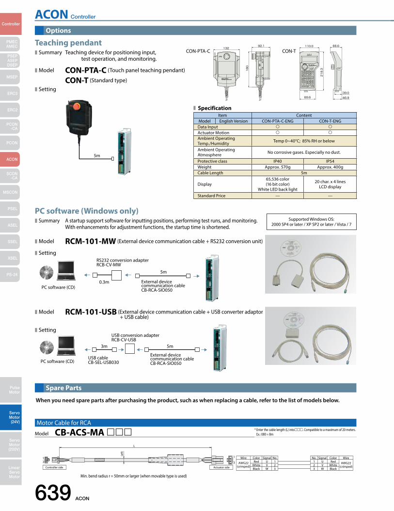
ACON Controller
639 ACON
PMECAMEC
Controller
Pulse Motor
Servo Motor (24V)
Servo Motor (200V)
LinearServo Motor
PSEP ASEPDSEP
MSEP
ERC3
ERC2
PCON-CA
PCON
ACON
SCON-CA
MSCON
PSEL
ASEL
SSEL
XSEL
PS-24
PC software (Windows only) Summary A startup support software for inputting positions, performing test runs, and monitoring. With enhancements for adjustment functions, the startup time is shortened.
Model RCM-101-MW (External device communication cable + RS232 conversion unit)
Setting
Model RCM-101-USB (External device communication cable + USB converter adaptor + USB cable)
Setting
External device communication cable CB-RCA-SIO050
USB conversion adapter RCB-CV-USB
USB cable CB-SEL-USB030
3m 5m
PC software (CD)
Teaching pendantSummary Teaching device for positioning input, test operation, and monitoring.
Model CON-PTA-C (Touch panel teaching pendant)
CON-T (Standard type)
Setting
RS232 conversion adapter RCB-CV-MW
External device communication cable CB-RCA-SIO050
0.3m
5m
PC software (CD)
Supported Windows OS: 2000 SP4 or later / XP SP2 or later / Vista / 7
CON-PTA-C CON-T
Options
Spare Parts
AWG22(crimped) White
Wire Color Signal No.U 1
No. Signal Color WireRed 1
23Black
VW
23 W
VU Red
WhiteBlack
AWG22(crimped)
13 3
1
L
Controller side
(ø9)
Actuator side
Model CB-ACS-MA Motor Cable for RCA
When you need spare parts after purchasing the product, such as when replacing a cable, refer to the list of models below.
Min. bend radius r = 50mm or larger (when movable type is used)
* Enter the cable length (L) into. Compatible to a maximum of 20 meters. Ex.: 080 = 8m
Item ContentModel English Version CON-PTA-C-ENG CON-T-ENG
Data Input Actuator Motion Ambient Operating Temp./Humidity Temp 0~40°C; 85% RH or below
Ambient Operating Atmosphere No corrosive gases. Especially no dust.
Protective class IP40 IP54Weight Approx. 570g Approx. 400gCable Length 5m
Display65,536 color(16 bit color)
White LED back light
20 char. x 4 lines LCD display
Standard Price — —
Specification
5m
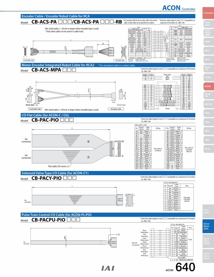
ACON Controller
ACON 640
PMECAMEC
Controller
Pulse Motor
Servo Motor (24V)
Servo Motor (200V)
LinearServo Motor
PSEP ASEPDSEP
MSEP
ERC3
ERC2
PCON-CA
PCON
ACON
SCON-CA
MSCON
PSEL
ASEL
SSEL
XSEL
PS-24
* Enter the cable length (L) into. Compatible to a maximum of 10 meters. Ex.: 080 = 8m
1
1112
2
(crimped)AWG28
Flat cable
51353-1200 (MOLEX)
No connector
LBrown-1
CableColorNo. Signal Wire
24V123456789
101112
0VIN0IN1IN2IN3
OUT0OUT1OUT2OUT3OUT4OUT5
Red-1Orange-1Yellow-1Green-1Blue-1
Purple-1Gray-1
White-1Black-1
Brown-2Red-2
Model CB-PACY-PIO Solenoid Valve Type I/O Cable (for ACON-CY)
* Enter the cable length (L) into. Compatible to a maximum of 10 meters. Ex.: 080 = 8m
0.2sq
51353-1400 (MOLEX)
No connector Side with
no connector
0.5-5 (JST)White/Gray
(ø9)
L
BlackBlack
CableColorNo. Signal Wire
IO_24V
FG
1
1 AWG24
White/BlackRed
White/RedGreen
White/GreenYellow
White/YellowBrown
White/BrownBlue
White/BlueGray
White/Gray
23456789
1011121314
IO_24GIN0IN1IN2IN3
OUT0OUT1OUT2OUT3
PPPGNPNG
White/BlackRed
White/RedGreen
White/GreenYellow
White/YellowBrown
White/BrownBlue
White/BlueGray
White/Gray
Model CB-PACPU-PIO Pulse Train Control I/O Cable (for ACON-PL/PO)
* Enter the cable length (L) into. Compatible to a maximum of 10 meters. Ex.: 080 = 8m
No. Signal name
Cable color Wiring
1A 24V Brown - 1
Flat cable A (crimped)
2A 24V Red - 13A — Orange - 14A — Yellow - 15A IN0 Green - 16A IN1 Blue - 17A IN2 Purple - 18A IN3 Gray - 19A IN4 White - 1
10A IN5 Black - 111A IN6 Brown - 212A IN7 Red - 213A IN8 Orange - 214A IN9 Yellow - 215A IN10 Green - 216A IN11 Blue - 217A IN12 Purple - 218A IN13 Gray - 219A IN14 White - 220A IN15 Black - 2
No. Signal name
Cable color Wiring
1B OUT0 Brown - 3
Flat cable B (crimped)AWG 28
2B OUT1 Red - 33B OUT2 Orange - 34B OUT3 Yellow - 35B OUT4 Green - 36B OUT5 Blue - 37B OUT6 Purple - 38B OUT7 Gray - 39B OUT8 White - 3
10B OUT9 Black - 311B OUT10 Brown - 412B OUT11 Red - 413B OUT12 Orange - 414B OUT13 Yellow - 415B OUT14 Green - 416B OUT15 Blue - 417B — Purple - 418B — Gray - 419B 0V White - 420B 0V Black - 4
HIF6-40D-1.27R
L
20A
1A
20B
1B
No connector
No connector
Flat cable (20 cores) x 2
A
B
Model CB-PAC-PIO I/O Flat Cable (for ACON-C / CG)
Encoder Cable / Encoder Robot Cable for RCA
* Enter the cable length (L) into. Compatible to a maximum of 20 meters. Ex.: 080 = 8m
L
U
Shield
Yellow (Red )Yellow (Blue )
Pink (Red )Pink (Blue )
White (Red )White (Blue )Orange (Red )Orange (Blue )
Gray (Red )Gray (Blue )
Orange (Red Consecutive)Orange (Blue Consecutive)Gray (Red Consecutive)Gray (Blue Consecutive)
Red(Wire color)
1 A1 USignal Pin No. Pin No. Signal
BK+ 16
(Front view)
(10)
(ø12
)
(18)
(8)
(12)
(23)
(8)
(5)
(30)
(18)
Controller side
(Front view)
Actuator side
(Front view)
BK−LS+LS−A+A−B+B−Z+Z−
/PSVCCGNDNCFG
151817141312111098765
1
VW
23
B1A2B2A3B3A4B4A5B5A6B6A7B7A8B8A9B9
A10B10A11B11
VWNCNCNCBK+BK−LS+LS−A+A−B+B−Z+Z−−
/PSVCCGNDNCFG
YellowBlack
Model CB-ACS-MPA Motor-Encoder Integrated Robot Cable for RCA2 * The standard cable is a robot cable.
Min. bend radius r = 84 mm or larger (when movable type is used)
* Enter the cable length (L) into. Compatible to a maximum of 20 meters. Ex.: 080 = 8m
1
9 18
10
20
18
2 1
17
Actuator sideController side
L
(ø10
)
White/Purple Blue LS+ 181 ENA Gray White/BlueRobot Cable Standard Cable
Housing : PHDR-18VR (JST)Contact : SPHD-001T-P0.5 (JST)
Plug housing : XMP-18V (JST)Socket contact : BXA-001T-P0.6 (JST)Retainer : XMS-09V (JST)
CN2CN1
Cable color Standard Cable Robot CablePin No.
Cable color SignalSignal Pin
No.
White/GrayYellow
BlueWhite/Blue
White/YellowWhite/Red
White/BlackOrangeGreenPurpleGrayRed
Black
Ground
OrangeGreenBrownGrayRed
BlackYellow
PinkPurpleWhite
Blue/redOrange/WhiteGreen/White
Ground
LS−BK+BK−ENAENAENBENBENZENZ
VPS5V
GND−−−
FG
1716151413121110987654321
23456789
101112131415161718
ENAENBENB
−−
LS+−
FGENZENZ
−VPS5V
GNDLS−BK−BK+
RedBlack
Yellow−−
Blue−
GroundPink
PurpleWhite
Blue/redOrange/WhiteGreen/White
OrangeBrownGreen
White/YellowWhite/Red
White/Black−−
White/Purple−
GroundOrangeGreenPurpleGrayRed
BlackWhite/Gray
BlueYellow
Model CB-ACS-PA /CB-ACS-PA -RBMin. bend radius r = 50 mm or larger (when movable type is used)* Only robot cable is to be used in a cable track.
* The standard cable for the encoder cable is the normal cable. A robot cable can be specified as an option.
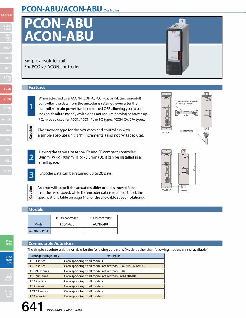
PCON-ABU/ACON-ABU Controller
641 PCON-ABU / ACON-ABU
PMECAMEC
Controller
Pulse Motor
Servo Motor (24V)
Servo Motor (200V)
LinearServo Motor
PSEP ASEPDSEP
MSEP
ERC3
ERC2
PCON-CA
PCON
ACON
SCON-CA
MSCON
PSEL
ASEL
SSEL
XSEL
PS-24
Simple absolute unitFor PCON / ACON controller
PCON-ABUACON-ABU
Corresponding series Reference
RCP3 series Corresponding to all models
RCP2 series Corresponding to all models other than HS8C/HS8R/RA10C.
RCP2CR series Corresponding to all models other than HS8C.
RCP2W series Corresponding to all models other than SA16C/RA10C.
RCA2 series Corresponding to all models
RCA series Corresponding to all models
RCACR series Corresponding to all models
RCAW series Corresponding to all models
The simple absolute unit is available for the following actuators. (Models other than following models are not available.)
PCON controller ACON controller
Model PCON-ABU ACON-ABU
Standard Price — —
Features
Models
Connectable Actuators
1
2
3ACON-CY
100m
m34mm
0.2m
Controller connection cableCB—AC(PC)—PJ002
Encoder CableACON-CY
When attached to a ACON/PCON-C, -CG, -CY, or -SE (incremental) controller, the data from the encoder is retained even after the controller's main power has been turned OFF, allowing you to use it as an absolute model, which does not require homing at power-up.* Cannot be used for ACON/PCON-PL or PO types, PCON-CA/CFA types.
The encoder type for the actuators and controllers with a simple absolute unit is "I" (incremental) and not "A" (absolute).Ca
utio
n
Having the same size as the CY and SE compact controllers 34mm (W) × 100mm (H) × 75.3mm (D), it can be installed in a small space.
Encoder data can be retained up to 20 days.
An error will occur if the actuator's slider or rod is moved faster than the fixed speed, while the encoder data is retained. Check the specifications table on page 642 for the allowable speed (rotations).Ca
utio
n
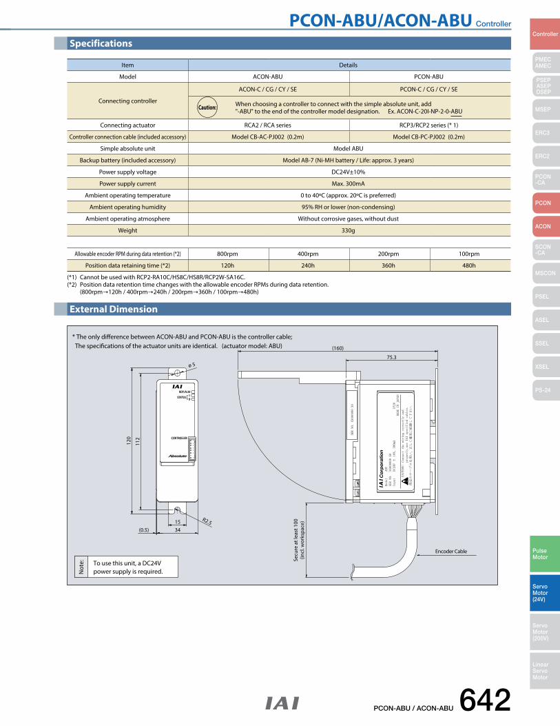
PCON-ABU/ACON-ABU Controller
PCON-ABU / ACON-ABU 642
PMECAMEC
Controller
Pulse Motor
Servo Motor (24V)
Servo Motor (200V)
LinearServo Motor
PSEP ASEPDSEP
MSEP
ERC3
ERC2
PCON-CA
PCON
ACON
SCON-CA
MSCON
PSEL
ASEL
SSEL
XSEL
PS-24
Specifications
External Dimension
120
112
(0.5)
ø 5
34
Secu
re a
t lea
st 1
00(in
cl. w
orks
pace
)
(160)
75.3
15 R2.5
* The only dierence between ACON-ABU and PCON-ABU is the controller cable; The specications of the actuator units are identical. (actuator model: ABU)
To use this unit, a DC24Vpower supply is required.
Encoder Cable
Not
e:
(*1) Cannot be used with RCP2-RA10C/HS8C/HS8R/RCP2W-SA16C.(*2) Position data retention time changes with the allowable encoder RPMs during data retention. (800rpm120h / 400rpm240h / 200rpm360h / 100rpm480h)
Item Details
Model ACON-ABU PCON-ABU
Connecting controller
ACON‐C / CG / CY / SE PCON‐C / CG / CY / SE
When choosing a controller to connect with the simple absolute unit, add "-ABU" to the end of the controller model designation. Ex. ACON‐C‐20I‐NP‐2‐0‐ABU
Connecting actuator RCA2 / RCA series RCP3/RCP2 series (* 1)
Controller connection cable (included accessory) Model CB‐AC‐PJ002 (0.2m) Model CB‐PC‐PJ002 (0.2m)
Simple absolute unit Model ABU
Backup battery (included accessory) Model AB‐7 (Ni‐MH battery / Life: approx. 3 years)
Power supply voltage DC24V±10%
Power supply current Max. 300mA
Ambient operating temperature 0 to 40ºC (approx. 20ºC is preferred)
Ambient operating humidity 95% RH or lower (non-condensing)
Ambient operating atmosphere Without corrosive gases, without dust
Weight 330g
Allowable encoder RPM during data retention (*2) 800rpm 400rpm 200rpm 100rpm
Position data retaining time (*2) 120h 240h 360h 480h
Caution:
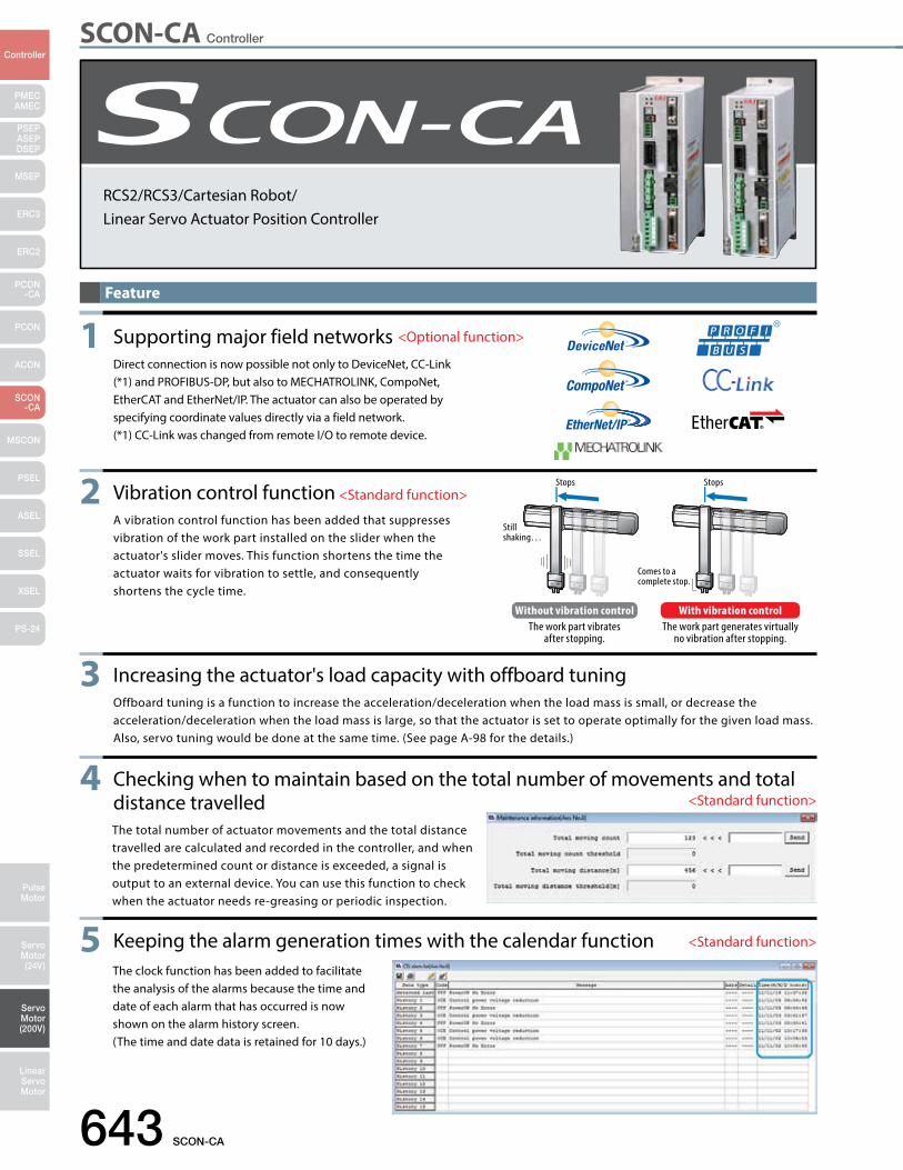
SCON-CA Controller
643 SCON-CA
PMECAMEC
Controller
Pulse Motor
Servo Motor (24V)
Servo Motor (200V)
LinearServo Motor
PSEP ASEPDSEP
MSEP
ERC3
ERC2
PCON-CA
PCON
ACON
SCON-CA
MSCON
PSEL
ASEL
SSEL
XSEL
PS-24
Feature
Stops Stops
Still shaking…
Comes to a complete stop.
Without vibration control The work part vibrates
after stopping.
With vibration control The work part generates virtually
no vibration after stopping.
1 Supporting major field networks Direct connection is now possible not only to DeviceNet, CC-Link
(*1) and PROFIBUS-DP, but also to MECHATROLINK, CompoNet, EtherCAT and EtherNet/IP. The actuator can also be operated by specifying coordinate values directly via a field network.
(*1) CC-Link was changed from remote I/O to remote device.
<Optional function>
2 Vibration control function A vibration control function has been added that suppresses
vibration of the work part installed on the slider when the actuator's slider moves. This function shortens the time the actuator waits for vibration to settle, and consequently shortens the cycle time.
<Standard function>
3 Increasing the actuator's load capacity with offboard tuning Offboard tuning is a function to increase the acceleration/deceleration when the load mass is small, or decrease the
acceleration/deceleration when the load mass is large, so that the actuator is set to operate optimally for the given load mass. Also, servo tuning would be done at the same time. (See page A-98 for the details.)
4 Checking when to maintain based on the total number of movements and total distance travelledThe total number of actuator movements and the total distance travelled are calculated and recorded in the controller, and when the predetermined count or distance is exceeded, a signal is output to an external device. You can use this function to check when the actuator needs re-greasing or periodic inspection.
<Standard function>
5 Keeping the alarm generation times with the calendar function <Standard function>
The clock function has been added to facilitate the analysis of the alarms because the time and date of each alarm that has occurred is now shown on the alarm history screen. (The time and date data is retained for 10 days.)
RCS2/RCS3/Cartesian Robot/Linear Servo Actuator Position Controller
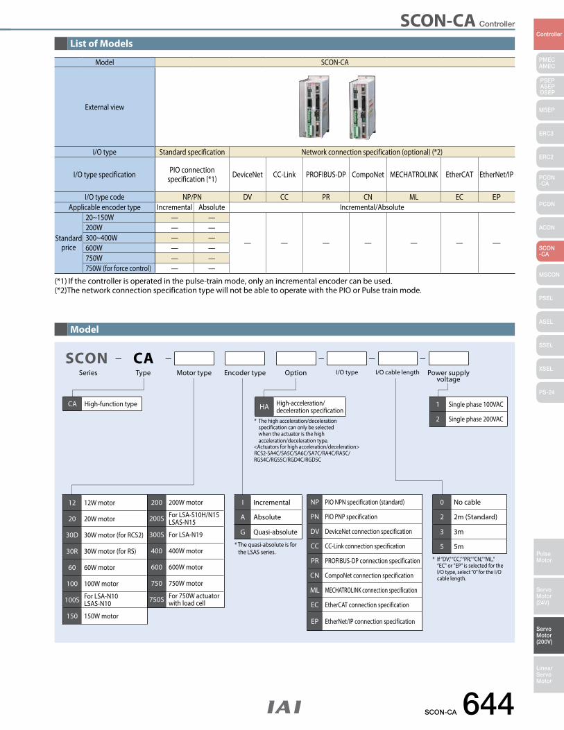
SCON-CA Controller
SCON-CA 644
PMECAMEC
Controller
Pulse Motor
Servo Motor (24V)
Servo Motor (200V)
LinearServo Motor
PSEP ASEPDSEP
MSEP
ERC3
ERC2
PCON-CA
PCON
ACON
SCON-CA
MSCON
PSEL
ASEL
SSEL
XSEL
PS-24
List of Models
Model
Model SCON-CA
External view
I/O type Standard specification Network connection specification (optional) (*2)
I/O type specification PIO connection specification (*1) DeviceNet CC-Link PROFIBUS-DP CompoNet MECHATROLINK EtherCAT EtherNet/IP
I/O type code NP/PN DV CC PR CN ML EC EPApplicable encoder type Incremental Absolute Incremental/Absolute
Standard price
20~150W — —
— — — — — — —
200W — —300~400W — —600W — —750W — —750W (for force control) — —
(*1) If the controller is operated in the pulse-train mode, only an incremental encoder can be used. (*2)The network connection specification type will not be able to operate with the PIO or Pulse train mode.
NP PIO NPN specification (standard)
PN PIO PNP specification
DV DeviceNet connection specification
CC CC-Link connection specification
PR PROFIBUS-DP connection specification
CN CompoNet connection specification
ML MECHATROLINK connection specification
EC EtherCAT connection specification
EP EtherNet/IP connection specification
Series Type Encoder typeMotor type Option I/O type Power supply voltage
I/O cable length
* The high acceleration/deceleration specification can only be selected when the actuator is the high acceleration/deceleration type. <Actuators for high acceleration/deceleration>RCS2-SA4C/SA5C/SA6C/SA7C/RA4C/RA5C/RGS4C/RGS5C/RGD4C/RGD5C
SCON CA
CA High-function type HA High-acceleration/deceleration specification
I Incremental
A Absolute
G Quasi-absolute
1 Single phase 100VAC
2 Single phase 200VAC
* If “DV,” “CC,” “PR,” “CN,” “ML,” “EC" or "EP" is selected for the I/O type, select “0” for the I/O cable length.
* The quasi-absolute is for the LSAS series.
12 12W motor
20 20W motor
30D 30W motor (for RCS2)
30R 30W motor (for RS)
60 60W motor
100 100W motor
100S For LSA-N10LSAS-N10
150 150W motor
200 200W motor
200S For LSA-S10H/N15LSAS-N15
300S For LSA-N19
400 400W motor
600 600W motor
750 750W motor
750S For 750W actuator with load cell
0 No cable
2 2m (Standard)
3 3m
5 5m
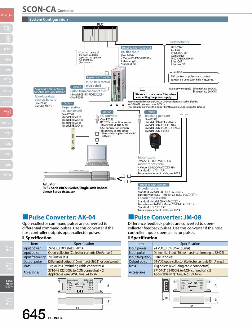
SCON-CA Controller
645 SCON-CA
PMECAMEC
Controller
Pulse Motor
Servo Motor (24V)
Servo Motor (200V)
LinearServo Motor
PSEP ASEPDSEP
MSEP
ERC3
ERC2
PCON-CA
PCON
ACON
SCON-CA
MSCON
PSEL
ASEL
SSEL
XSEL
PS-24
System ConfigurationPLC
Field networkDeviceNetCC-LinkPROFIBUS-DPCompoNetMECHATROLINK-I/IIEtherCATEtherNet/IP
I/O flat cable (See P654)<Model CB-PAC-PIO020>Cable lengthStandard 2m
Pulse-train control plug + shell
Pulse-train control cable<Model CB-SC-PIOS>(See P654)
Main power supply Single phase 100VAC Single phase 200VAC
Recommended model: NF2010A-UP (Manufacturer: Soshin Electric)NAC-10-472 (Manufacturer: COSEL)(You can also purchase this noise filter through IAI. Contact us for details.)
Absolute data backup battery(See P652)<Model AB-5>
PC software (See P652)RC 232 connection version <Model RCM-101-MW>USB connection version <Model RCM-101-USB>* The cable is supplied with the PC software.
Teaching pendant(See P652)<Model CON-PTA-C-ENG><Model CON-PDA-C-ENG><Model CON-PGAS-C-S-ENG><Model CON-T-ENG>
Motor cable<Model CB-RCC-MA>Motor robot cable<Model CB-RCC-MA-RB>Standard: 1m / 3m / 5mFor a replalclement cable, see P653.
ActuatorRCS2 Series/RCS3 Series/Single-Axis Robot/Linear Servo Actuator
* Be sure to use a noise filter when connecting the power supply.
* If the host unit is of the open-collector type, use the optional AK-04/JM-08. (See below.)
50
10
OpencollectorInput1 24V2 GND3 PP4 NP
DifferentialOutput
PP 1/PP 2NP 3
/NP 4
1020
Item SpecificationInput power 24 VDC±10% (Max. 50mA)Input pulse Open-collector (Collector current: 12mA max.)Input frequency 200kHz or lessOutput pulse Differential output (10mA max.) (26C31 or equivalent)Mass 10g or less (excluding cable connectors)
Accessories 37104-3122-000L (e-CON connector) x 2 Applicable wire: AWG Nos. 24 to 26
Item SpecificationInput power 24 VDC±10% (Max. 50mA)Input pulse Differential input (10 mA max.) (conforming to RS422)Input frequency 500kHz or lessOutput pulse 24-VDC open-collector (Collector current: 25mA max.)Mass 10g or less (excluding cable connectors)
Accessories 37104-3122-000FL (e-CON connector) x 2 Applicable wire: AWG Nos. 24 to 26
Pulse Converter: AK-04Open-collector command pulses are converted to differential command pulses. Use this converter if the host controller outputs open-collector pulses.Specification Specification
Pulse Converter: JM-08Difference feedback pulses are converted to open-collector feedback pulses. Use this converter if the host controller inputs open-collector pulses.
50
OpencollectorInput1 24V2 GND3 PP4 NP
DifferentialOutput
PP 1/PP 2NP 3
/NP 4
1020
PIO control or pulse-train control cannot be used with field networks.
Caution
Regenerative resistance unit(See P652)<Model RESU-2><Model RESUD-2><Model RESU-1><Model RESUD-1>
Option
Option Option
Supplied with Controller
Supplied with Controller
Encoder cableStandard <Model CB-RCS2-PA>For rotary or RA13R <Model CB-RCS2-PLA>Encoder robot cableStandard <Model CB-X3-PA>For rotary or RA13R <Model CB-X2-PLA>Standard: 1m / 3m / 5mFor a replalclement cable, see P653.
Supplied with Actuator
OptionSupplied with Controller
for Absolute Specification
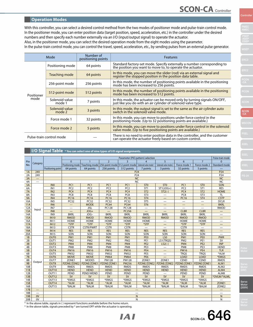
SCON-CA Controller
SCON-CA 646
PMECAMEC
Controller
Pulse Motor
Servo Motor (24V)
Servo Motor (200V)
LinearServo Motor
PSEP ASEPDSEP
MSEP
ERC3
ERC2
PCON-CA
PCON
ACON
SCON-CA
MSCON
PSEL
ASEL
SSEL
XSEL
PS-24
Mode Number of positioning points Features
Positioner mode
Positioning mode 64 points Standard factory-set mode. Specify externally a number corresponding to the position you want to move to, to operate the actuator.
Teaching mode 64 points In this mode, you can move the slider (rod) via an external signal and register the stopped position in the position data table.
256-point mode 256 points In this mode, the number of positioning points available in the positioning mode has been increased to 256 points.
512-point mode 512 points In this mode, the number of positioning points available in the positioning mode has been increased to 512 points.
Solenoid value mode 1 7 points In this mode, the actuator can be moved only by turning signals ON/OFF,
just like you do with an air cylinder of solenoid valve type.
Solenoid value mode 2 3 points In this mode, the output signal is set to the same as the air cylinder auto
switch in the solenoid valve mode.
Force mode 1 32 points In this mode, you can move to positions under force control in the positioning mode. (Up to 32 positioning points are available.)
Force mode 2 5 points In this mode, you can move to positions under force control in the solenoid valve mode. (Up to five positioning points are available.)
Pulse-train control mode — There is no need to enter position data in the controller, and the customer can operate the actuator freely based on custom control.
Pin No. Category
Parameter (PIO pattern) selection Pulse-train mode0 1 2 3 4 5 6 7 0
Positioning mode Teaching mode 256-point mode 512-point mode Solenoid valve mode 1 Solenoid valve mode 2 Force mode 1 Force mode 2 Standard modePositioning point 64 points 64 points 256 points 512 points 7 points 3 points 32 points 5 points —
1A 24V P24 P242A 24V P24 P243A — NC NC4A — NC NC5A
Input
IN0 PC1 PC1 PC1 PC1 ST0 ST0 PC1 ST0 SON6A IN1 PC2 PC2 PC2 PC2 ST1 ST1(JOG+) PC2 ST1 RES7A IN2 PC4 PC4 PC4 PC4 ST2 ST2(–) PC4 ST2 HOME8A IN3 PC8 PC8 PC8 PC8 ST3 — PC8 ST3 TL9A IN4 PC16 PC16 PC16 PC16 ST4 — PC16 ST4 CSTP
10A IN5 PC32 PC32 PC32 PC32 ST5 — — — DCLR11A IN6 — MODE PC64 PC64 ST6 — — — BKRL12A IN7 — JISL PC128 PC128 — — — — RMOD13A IN8 — JOG+ — PC256 — — CLBR CLBR —14A IN9 BKRL JOG– BKRL BKRL BKRL BKRL BKRL BKRL —15A IN10 RMOD RMOD RMOD RMOD RMOD RMOD RMOD RMOD —16A IN11 HOME HOME HOME HOME HOME — HOME HOME —17A IN12 *STP *STP *STP *STP *STP — *STP *STP —18A IN13 CSTR CSTR/PWRT CSTR CSTR — — CSTR — —19A IN14 RES RES RES RES RES RES RES RES —20A IN15 SON SON SON SON SON SON SON SON —1B
Output
OUT0 PM1 PM1 PM1 PM1 PE0 LS0 PM1 PE0 PWR2B OUT1 PM2 PM2 PM2 PM2 PE1 LS1(TRQS) PM2 PE1 SV3B OUT2 PM4 PM4 PM4 PM4 PE2 LS2(–) PM4 PE2 INP4B OUT3 PM8 PM8 PM8 PM8 PE3 — PM8 PE3 HEND5B OUT4 PM16 PM16 PM16 PM16 PE4 — PM16 PE4 TLR6B OUT5 PM32 PM32 PM32 PM32 PE5 — TRQS TRQS *ALM7B OUT6 MOVE MOVE PM64 PM64 PE6 — LOAD LOAD *EMGS8B OUT7 ZONE1 MODES PM128 PM128 ZONE1 ZONE1 CEND CEND RMDS9B OUT8 PZONE/ZONE2 PZONE/ZONE1 PZONE/ZONE1 PM256 PZONE/ZONE2 PZONE/ZONE2 PZONE/ZONE1 PZONE/ZONE1 ALM1
10B OUT9 RMDS RMDS RMDS RMDS RMDS RMDS RMDS RMDS ALM211B OUT10 HEND HEND HEND HEND HEND HEND HEND HEND ALM412B OUT11 PEND PEND/WEND PEND PEND PEND — PEND PEND ALM813B OUT12 SV SV SV SV SV SV SV SV *OVLW/*ALML14B OUT13 *EMGS *EMGS *EMGS *EMGS *EMGS *EMGS *EMGS *EMGS —15B OUT14 *ALM *ALM *ALM *ALM *ALM *ALM *ALM *ALM ZONE116B OUT15 *BALM *BALM *BALM *BALM *BALM *BALM *BALM *BALM ZONE217B — — —18B — — —19B 0V N N20B 0V N N
Operation Modes
I/O Signal Table * You can select one of nine types of I/O signal assignments.
With this controller, you can select a desired control method from the two modes of positioner mode and pulse-train control mode. In the positioner mode, you can enter position data (target position, speed, acceleration, etc.) in the controller under the desired numbers and then specify each number externally via an I/O (input/output signal) to operate the actuator. Also, in the positioner mode, you can select the desired operation mode from the eight modes using the parameter.In the pulse-train control mode, you can control the travel, speed, acceleration, etc., by sending pulses from an external pulse generator.
* In the above table, signals in ( ) represent functions available before the home return. * In the above table, signals preceded by * are turned OFF while the actuator is operating.
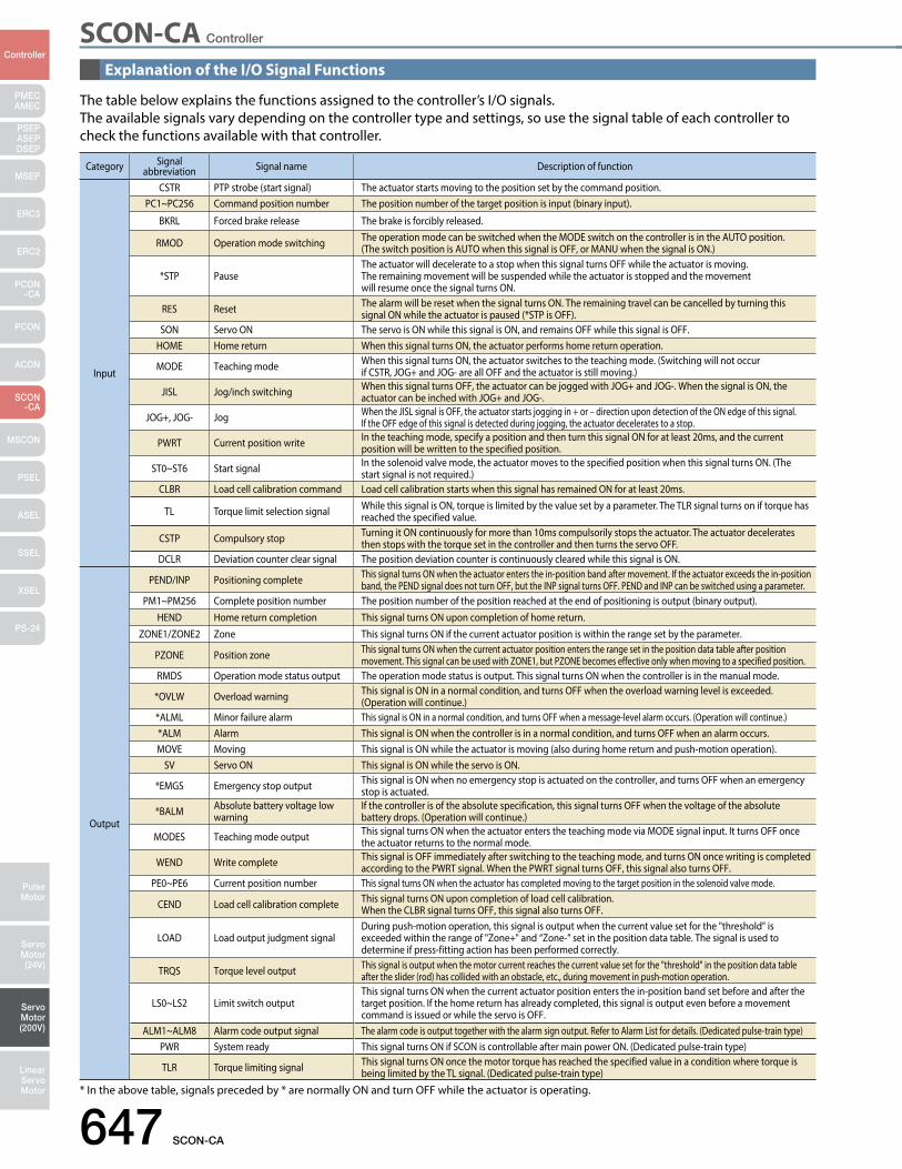
SCON-CA Controller
647 SCON-CA
PMECAMEC
Controller
Pulse Motor
Servo Motor (24V)
Servo Motor (200V)
LinearServo Motor
PSEP ASEPDSEP
MSEP
ERC3
ERC2
PCON-CA
PCON
ACON
SCON-CA
MSCON
PSEL
ASEL
SSEL
XSEL
PS-24
Explanation of the I/O Signal Functions
The table below explains the functions assigned to the controller’s I/O signals. The available signals vary depending on the controller type and settings, so use the signal table of each controller to check the functions available with that controller.
Category Signal abbreviation Signal name Description of function
Input
CSTR PTP strobe (start signal) The actuator starts moving to the position set by the command position.PC1~PC256 Command position number The position number of the target position is input (binary input).
BKRL Forced brake release The brake is forcibly released.
RMOD Operation mode switching The operation mode can be switched when the MODE switch on the controller is in the AUTO position. (The switch position is AUTO when this signal is OFF, or MANU when the signal is ON.)
*STP PauseThe actuator will decelerate to a stop when this signal turns OFF while the actuator is moving. The remaining movement will be suspended while the actuator is stopped and the movement will resume once the signal turns ON.
RES Reset The alarm will be reset when the signal turns ON. The remaining travel can be cancelled by turning this signal ON while the actuator is paused (*STP is OFF).
SON Servo ON The servo is ON while this signal is ON, and remains OFF while this signal is OFF.HOME Home return When this signal turns ON, the actuator performs home return operation.
MODE Teaching mode When this signal turns ON, the actuator switches to the teaching mode. (Switching will not occur if CSTR, JOG+ and JOG- are all OFF and the actuator is still moving.)
JISL Jog/inch switching When this signal turns OFF, the actuator can be jogged with JOG+ and JOG-. When the signal is ON, the actuator can be inched with JOG+ and JOG-.
JOG+, JOG- Jog When the JISL signal is OFF, the actuator starts jogging in + or – direction upon detection of the ON edge of this signal. If the OFF edge of this signal is detected during jogging, the actuator decelerates to a stop.
PWRT Current position write In the teaching mode, specify a position and then turn this signal ON for at least 20ms, and the current position will be written to the specified position.
ST0~ST6 Start signal In the solenoid valve mode, the actuator moves to the specified position when this signal turns ON. (The start signal is not required.)
CLBR Load cell calibration command Load cell calibration starts when this signal has remained ON for at least 20ms.
TL Torque limit selection signal While this signal is ON, torque is limited by the value set by a parameter. The TLR signal turns on if torque has reached the specified value.
CSTP Compulsory stop Turning it ON continuously for more than 10ms compulsorily stops the actuator. The actuator decelerates then stops with the torque set in the controller and then turns the servo OFF.
DCLR Deviation counter clear signal The position deviation counter is continuously cleared while this signal is ON.
Output
PEND/INP Positioning complete This signal turns ON when the actuator enters the in-position band after movement. If the actuator exceeds the in-position band, the PEND signal does not turn OFF, but the INP signal turns OFF. PEND and INP can be switched using a parameter.
PM1~PM256 Complete position number The position number of the position reached at the end of positioning is output (binary output).HEND Home return completion This signal turns ON upon completion of home return.
ZONE1/ZONE2 Zone This signal turns ON if the current actuator position is within the range set by the parameter.
PZONE Position zone This signal turns ON when the current actuator position enters the range set in the position data table after position movement. This signal can be used with ZONE1, but PZONE becomes effective only when moving to a specified position.
RMDS Operation mode status output The operation mode status is output. This signal turns ON when the controller is in the manual mode.
*OVLW Overload warning This signal is ON in a normal condition, and turns OFF when the overload warning level is exceeded. (Operation will continue.)
*ALML Minor failure alarm This signal is ON in a normal condition, and turns OFF when a message-level alarm occurs. (Operation will continue.)*ALM Alarm This signal is ON when the controller is in a normal condition, and turns OFF when an alarm occurs.MOVE Moving This signal is ON while the actuator is moving (also during home return and push-motion operation).
SV Servo ON This signal is ON while the servo is ON.
*EMGS Emergency stop output This signal is ON when no emergency stop is actuated on the controller, and turns OFF when an emergency stop is actuated.
*BALM Absolute battery voltage low warning
If the controller is of the absolute specification, this signal turns OFF when the voltage of the absolute battery drops. (Operation will continue.)
MODES Teaching mode output This signal turns ON when the actuator enters the teaching mode via MODE signal input. It turns OFF once the actuator returns to the normal mode.
WEND Write complete This signal is OFF immediately after switching to the teaching mode, and turns ON once writing is completed according to the PWRT signal. When the PWRT signal turns OFF, this signal also turns OFF.
PE0~PE6 Current position number This signal turns ON when the actuator has completed moving to the target position in the solenoid valve mode.
CEND Load cell calibration complete This signal turns ON upon completion of load cell calibration. When the CLBR signal turns OFF, this signal also turns OFF.
LOAD Load output judgment signalDuring push-motion operation, this signal is output when the current value set for the "threshold" is exceeded within the range of "Zone+" and “Zone-” set in the position data table. The signal is used to determine if press-fitting action has been performed correctly.
TRQS Torque level output This signal is output when the motor current reaches the current value set for the "threshold" in the position data table after the slider (rod) has collided with an obstacle, etc., during movement in push-motion operation.
LS0~LS2 Limit switch outputThis signal turns ON when the current actuator position enters the in-position band set before and after the target position. If the home return has already completed, this signal is output even before a movement command is issued or while the servo is OFF.
ALM1~ALM8 Alarm code output signal The alarm code is output together with the alarm sign output. Refer to Alarm List for details. (Dedicated pulse-train type)PWR System ready This signal turns ON if SCON is controllable after main power ON. (Dedicated pulse-train type)
TLR Torque limiting signal This signal turns ON once the motor torque has reached the specified value in a condition where torque is being limited by the TL signal. (Dedicated pulse-train type)
* In the above table, signals preceded by * are normally ON and turn OFF while the actuator is operating.
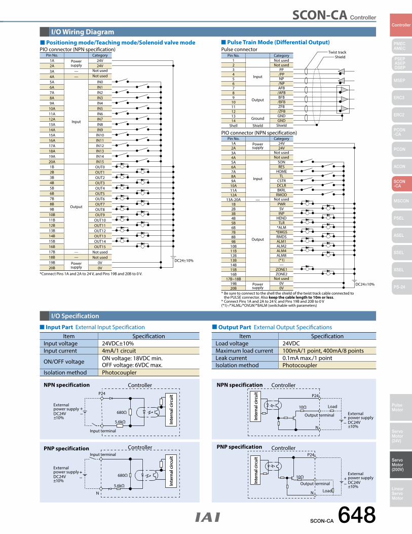
SCON-CA Controller
SCON-CA 648
PMECAMEC
Controller
Pulse Motor
Servo Motor (24V)
Servo Motor (200V)
LinearServo Motor
PSEP ASEPDSEP
MSEP
ERC3
ERC2
PCON-CA
PCON
ACON
SCON-CA
MSCON
PSEL
ASEL
SSEL
XSEL
PS-24
PNP specification
N
680Ω
5.6kΩ
Input terminal
External power supplyDC24V±10%
Controller
Inte
rnal
cir
cuit
ControllerNPN specificationP24
680Ω
5.6kΩ
Input terminal
External power supplyDC24V±10%
Inte
rnal
cir
cuit
ControllerNPN specification
P24
N
10Ω
Output terminal External power supplyDC24V±10%
Inte
rnal
circ
uit
ControllerPNP specificationP24
N
10Ω
Load
Output terminal
External power supplyDC24V±10%
Inte
rnal
circ
uit
Item SpecificationInput voltage 24VDC±10%Input current 4mA/1 circuit
ON/OFF voltage ON voltage: 18VDC min.OFF voltage: 6VDC max.
Isolation method Photocoupler
Item SpecificationLoad voltage 24VDCMaximum load current 100mA/1 point, 400mA/8 pointsLeak current 0.1mA max./1 pointIsolation method Photocoupler
* Be sure to connect to the shell the shield of the twist track cable connected to the PULSE connector. Also keep the cable length to 10m or less. * Connect Pins 1A and 2A to 24 V, and Pins 19B and 20B to 0 V(*1)-/*ALML/*OVLW/*BALM (switchable with parameters)
Load
I/O Wiring Diagram
I/O Specification
Output Part External Output Specifications
Positioning mode/Teaching mode/Solenoid valve mode
Input Part External Input Specification
Pulse Train Mode (Differential Output)
DC24±10%
Pin No. Category1A Power
supply24V
2A 24V3A — Not used4A — Not used5A
Input
IN06A IN17A IN28A IN39A IN4
10A IN511A IN612A IN713A IN814A IN915A IN1016A IN1117A IN1218A IN1319A IN1420A IN151B
Output
OUT02B OUT13B OUT24B OUT35B OUT46B OUT57B OUT68B OUT79B OUT8
10B OUT911B OUT1012B OUT1113B OUT1214B OUT1315B OUT1416B OUT1517B — Not used18B — Not used19B Power
supply0V
20B 0V*Connect Pins 1A and 2A to 24 V, and Pins 19B and 20B to 0 V.
PIO connector (NPN specification)
DC24±10%
Pin No. Category1A Power
supply24V
2A 24V3A Not used4A Not used5A
Input
SON6A RES7A HOME8A TL9A CSTR
10A DCLR11A BKRL12A RMOD
13A-20A — Not used1B
Output
PWR2B SV3B INP4B HEND5B TLR6B *ALM7B *EMGS8B RMDS9B ALM1
10B ALM211B ALM412B ALM813B (*1)14B —15B ZONE116B ZONE2
17B~18B Not used19B Power
supply0V
20B 0V
PIO connector (NPN specification)
Twist trackShieldPin No. Category
1 Not used2 Not used3
Input
PP4 /PP5 NP6 /NP7
Output
AFB8 /AFB9 BFB
10 /BFB11 ZFB12 /ZFB13 Ground
GND14 GND
Shell Shield Shield
Pulse connector
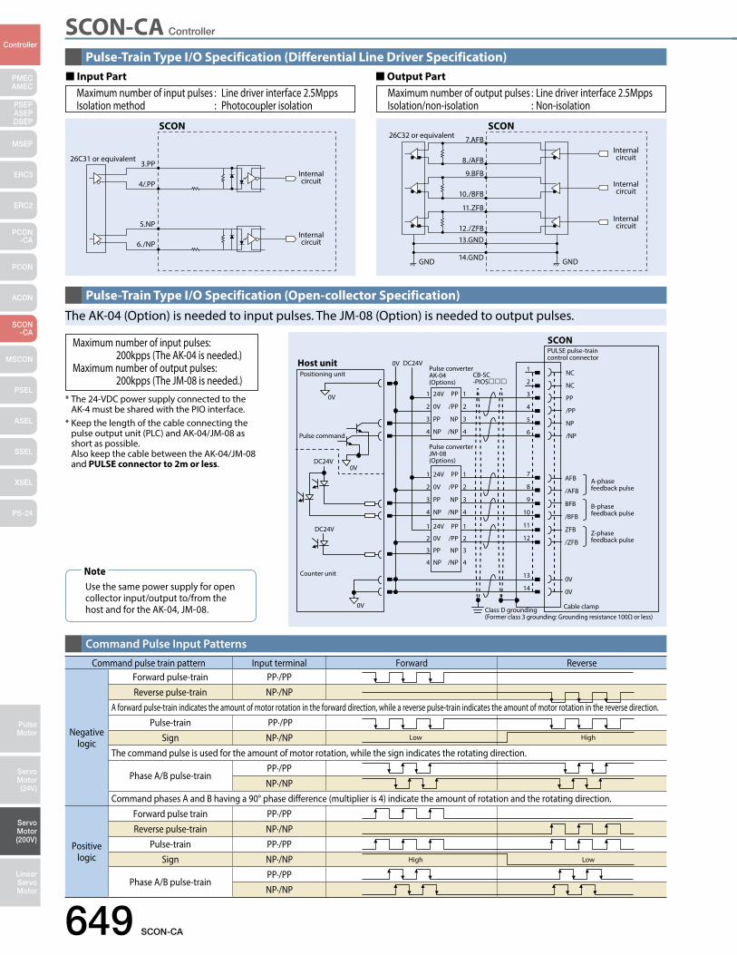
649 SCON-CA
PMECAMEC
Controller
Pulse Motor
Servo Motor (24V)
Servo Motor (200V)
LinearServo Motor
PSEP ASEPDSEP
MSEP
ERC3
ERC2
PCON-CA
PCON
ACON
SCON-CA
MSCON
PSEL
ASEL
SSEL
XSEL
PS-24
SCON-CA Controller
SCON
26C31 or equivalent3.PP
4/.PP
5.NP
6./NP
Internal circuit
Internal circuit
SCON26C32 or equivalent
GND
7.AFB
8./AFB
9.BFB
10./BFB
11.ZFB
12./ZFB13.GND
14.GND GND
Internal circuit
Internal circuit
Internal circuit
Positioning unit
Pulse command
Pulse converterAK-04 (Options)
PULSE pulse-train control connector
Pulse converterJM-08 (Options)
Counter unit
0V
0V
0V
0V
A-phase feedback pulse
B-phase feedback pulse
Z-phase feedback pulse
Cable clampClass D grounding (Former class 3 grounding: Grounding resistance 100Ω or less)
DC24V
1 24V PP 1
2 0V /PP 2
3 PP NP 3
4 NP /NP 4
1
2
3
4
5
6
7
8
9
10
11
12
13
14
NC
NC
PP
/PP
NP
/NP
1 24V PP 1
2 0V /PP 2
3 PP NP 3
4 NP /NP 4
1 24V PP 1
2 0V /PP 2
3 PP NP 3
4 NP /NP 4
DC24V
CB-SC-PIOS
DC24V
SCON
Host unit
0V
0V
AFB
/AFB
BFB
/BFB
ZFB
/ZFB
Command pulse train pattern Input terminal Forward Reverse
Negative logic
Forward pulse-train PP·/PPReverse pulse-train NP·/NP
A forward pulse-train indicates the amount of motor rotation in the forward direction, while a reverse pulse-train indicates the amount of motor rotation in the reverse direction. Pulse-train PP·/PP
Sign NP·/NPThe command pulse is used for the amount of motor rotation, while the sign indicates the rotating direction.
Phase A/B pulse-train PP·/PPNP·/NP
Command phases A and B having a 90° phase difference (multiplier is 4) indicate the amount of rotation and the rotating direction.
Positive logic
Forward pulse train PP·/PPReverse pulse-train NP·/NP
Pulse-train PP·/PPSign NP·/NP
Phase A/B pulse-train PP·/PPNP·/NP
High Low
Low High
Pulse-Train Type I/O Specification (Differential Line Driver Specification)
Pulse-Train Type I/O Specification (Open-collector Specification)
Command Pulse Input Patterns
Input Part Output Part
Use the same power supply for open collector input/output to/from the host and for the AK-04, JM-08.
Note
* The 24-VDC power supply connected to the AK-4 must be shared with the PIO interface. * Keep the length of the cable connecting the pulse output unit (PLC) and AK-04/JM-08 as short as possible. Also keep the cable between the AK-04/JM-08 and PULSE connector to 2m or less.
Maximum number of input pulses: 200kpps (The AK-04 is needed.)Maximum number of output pulses: 200kpps (The JM-08 is needed.)
The AK-04 (Option) is needed to input pulses. The JM-08 (Option) is needed to output pulses.
Maximum number of input pulses : Line driver interface 2.5MppsIsolation method : Photocoupler isolation
Maximum number of output pulses : Line driver interface 2.5MppsIsolation/non-isolation : Non-isolation
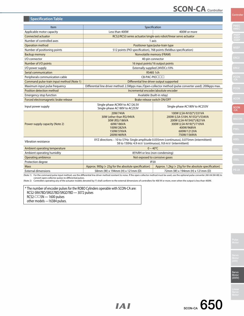
SCON-CA 650
PMECAMEC
Controller
Pulse Motor
Servo Motor (24V)
Servo Motor (200V)
LinearServo Motor
PSEP ASEPDSEP
MSEP
ERC3
ERC2
PCON-CA
PCON
ACON
SCON-CA
MSCON
PSEL
ASEL
SSEL
XSEL
PS-24
SCON-CA Controller
* The number of encoder pulses for the ROBO Cylinders operable with SCON-CA are: RCS2-SRA7BD/SRGS7BD/SRGD7BD — 3072 pulses RCS2-5N — 1600 pulses other models —16384 pulses.
Item SpecificationApplicable motor capacity Less than 400W 400W or moreConnected actuator RCS2/RCS3 series actuator/single-axis robot/linear servo actuatorNumber of controlled axes 1 axisOperation method Positioner type/pulse-train typeNumber of positioning points 512 points (PIO specification), 768 points (fieldbus specification)Backup memory Nonvolatile memory (FRAM)I/O connector 40-pin connectorNumber of I/O points 16 input points/16 output pointsI/O power supply Externally supplied 24VDC±10%Serial communication RS485 1chPeripherals communication cable CB-PAC-PIOCommand pulse-train input method (Note 1) Differential line driver output supportedMaximum input pulse frequency Differential line driver method: 2.5Mpps max./Open-collector method (pulse converter used): 200kpps max.Position detection method Incremental encoder/absolute encoderEmergency stop function Available (built-in relay)Forced electromagnetic brake release Brake release switch ON/OFF
Input power supply Single-phase AC90V to AC126.5VSingle-phase AC180V to AC253V Single-phase AC180V to AC253V
Power-supply capacity (Note 2)
20W/74VA30W (other than RS)/94VA
30W (RS)/186VA60W/186VA
100W/282VA150W/376VA200W/469VA
100W (LSA-N10)(*)/331VA200W (LSA-S10H, N15S)(*)/534VA
200W (LSA-N15H)(*)/821VA300W (LSA-N19)(*)/710VA
400W/968VA600W/1212VA750W/1569VA
Vibration resistance XYZ directions – 10 to 57Hz: Single amplitude 0.035mm (continuous), 0.075mm (intermittent)58 to 150Hz: 4.9 m/s2 (continuous), 9.8 m/s2 (intermittent)
Ambient operating temperature 0 ~ 40°CAmbient operating humidity 85%RH or less (non-condensing)Operating ambience Not exposed to corrosive gasesProtection degree IP20Mass Approx. 900g (+ 25g for the absolute specification) Approx. 1.2kg (+ 25g for the absolute specification)External dimensions 58mm (W) x 194mm (H) x 121mm (D) 72mm (W) x 194mm (H) x 121mm (D)
(Note 1) For the command pulse input method, use the differential line driver method resistant to noise. If the open-collector method must be used, use the optional pulse converter (AK-04/JM-08) to convert open-collector pulses to differential pulses. (Note 2) Controllers operating any of the actuator models denoted by (*) shall conform to the external dimensions of controllers for 400 W or more, even when the output is less than 400W.
Specification Table
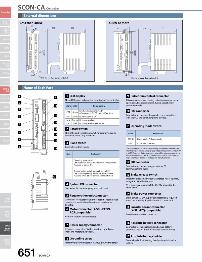
SCON-CA Controller
651 SCON-CA
PMECAMEC
Controller
Pulse Motor
Servo Motor (24V)
Servo Motor (200V)
LinearServo Motor
PSEP ASEPDSEP
MSEP
ERC3
ERC2
PCON-CA
PCON
ACON
SCON-CA
MSCON
PSEL
ASEL
SSEL
XSEL
PS-24
External dimensions
Name of Each Part
58
4.2
184
519
4(2
00.5
)
ø4.229 121(80)
With the absolute battery installed
Less than 400W72
4.2
184
519
4(2
00.5
)
ø4.243 121
With the absolute battery installed
(80)
400W or more
17
1
2
3
4
5
6
7
8
14
13
12
11
10
9
15
16
LED display These LED colors indicate the condition of the controller.
Rotary switch This is the address setting switch for identifying each controller when they are linked.
Piano switch Controller system switch.
1
2
3
Regeneration unit connectorConnector for resistance unit that absorbs regeneration current produced when the actuator decelerates to a stop.
Motor connector (X-SEL, ECON, RCS compatible)
Actuator motor cable connector.
Power supply connectorAC power connector. Divided into the control power input and motor power input.
Grounding screwProtective grounding screw. Always ground this screw.
System I/O connectorConnector for the emergency stop switch etc.
4
5
6
7
8
*The emergency stop switch on the teaching pendant becomes effective when the line is connected, regardless of whether this switch is set to AUTO or MANU. Take note that an emergency stop will be actuated momentarily when the teaching-pendant or SIO communication cable is disconnected. This is a normal phenomenon and does not indicate an error.
SIO connectorConnector for the teaching pendant or PC communications cable.
Brake release switchThis is the electromagnetic brake forced release switch, integrated with the actuator.
*It is necessary to connect the DC 24V power for the brake drive.
Brake power connectorBrake power DC 24V supply connector (only required when the brake equipped actuator is connected)
Encoder sensor connector (X-SEL-P/Q compatible)
Encoder sensor cable connector
Absolute battery connectorConnector for the absolute data backup battery. (Required only for absolute encoder specifications)
Absolute battery holderBattery holder for installing the absolute data backup battery
17
16
15
14
13
12
Pulse train control connector This connector is used during pulse train control mode operations. It is disconnected during operations in positioner mode.
PIO connectorConnector for the cable for parallel communications with the PLC and other peripheral devices.
Operating mode switch11
10
9
Name Color Explanation
PWR Green Lit when the system is ready (after power is ON CPU normal functions)
SV Green Lit when servo is ON
ALM Orange Lit during an alarm
EMG Red Lit during an emergency stop
Name Explanation
1Operating mode switchOFF: positioner mode ON: pulse train control mode *Enabled at power ON.
2Remote update switch (normally set to OFF) OFF: normal operating mode ON: update mode*Enabled when power is ON or during soft reset.
Name Explanation
MANU Do not receive PIO commands
AUTO Accept PIO commands
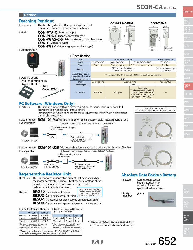
SCON-CA Controller
SCON-CA 652
PMECAMEC
Controller
Pulse Motor
Servo Motor (24V)
Servo Motor (200V)
LinearServo Motor
PSEP ASEPDSEP
MSEP
ERC3
ERC2
PCON-CA
PCON
ACON
SCON-CA
MSCON
PSEL
ASEL
SSEL
XSEL
PS-24
Options
PC Software (Windows Only)
Teaching Pendant
Features This startup support software provides functions to input positions, perform test operations and monitor data, among others. Incorporating all functions needed to make adjustments, this software helps shorten the initial startup time.
Model number RCM-101-MW (With external device communication cable + RS232 conversion unit) Configuration
Features This teaching device offers position input, test operation, monitoring and other functions.
Model CON-PTA-C (Standard type) CON-PDA-C (Deadman switch type) CON-PGAS-C-S (Safety-category compliant type) CON-T (Standard type) CON-TGS (Safety-category compliant type)
Model number RCM-101-USB (With external device communication cable + USB adapter + USB cable) Configuration
RS232 conversion adapter RCB-CV-MW
External device communication cable CB-RCA-SIO050
0.3m
5m
PC software (CD)
External device communication cable CB-RCA-SIO050
USB conversion adapter RCB-CV-USB
USB cable CB-SEL-USB030
3m 5m
PC software (CD)
Offboard tuning is supported only in Ver. 8.05.00.00 or later.
Offboard tuning is supported only in Ver. 8.05.00.00 or later.
CON-PTA-C-ENG CON-T-ENG
SpecificationItem Touch panel teaching Teaching pendant
Model CON-PTA-C-ENG CON-PDA-C-ENG CON-PGAS-C-S-ENG CON-T-ENGType Standard Deadman switch Safety-category compliant Standard
Display 65,536 colors (16 bit color)White LED backlight
20 characters x 4 linesLCD display
Ambient operating temperature/humidity Temperature 0 to 40ºC, humidity 85%RH or less (Non-condensing)
Protection degree IP40 IP54Mass Approx. 570g Approx. 600g Approx. 400g
Cable length 5m
Accessories Touch pen Touch pen
Touch penTP adapter (model: RCB-LB-TG)dummy plug (model: DP-4)controller connector cable
(model: CB-CON-LB005)
—
Configuration
Supported Windows OS: 2000 SP4 or later / XP SP2 or later / Vista / 7
Absolute Data Backup Battery Features Absolute data backup battery used when an actuator of absolute specification is operated.
Model number AB-5
Regenerative Resistor UnitFeatures This unit converts regenerative current that generates when the motor decelerates, to heat. Check the total wattage of the actuators to be operated and provide a regenerative resistance unit or units if required.
Model RESU-2 (Standard specification) RESUD-2 (DIN rail mount specification) RESU-1 (Standard specification, second or subsequent unit) RESUD-1 (DIN rail mount specification, second or subsequent unit)
* If two regenerative units are required, arrange one RESU-2/ RESUD-2 (1st) and one RESU-1/ RESUD-1 (2nd or after).
Horizontal Vertical0 unit ~ 100W ~ 100W1 unit ~ 400W ~ 400W2 units ~ 750W ~ 750W
Lead 2.5 Lead 1.25Horizontal 1 unit 0 unitVertical 1 unit 1 unit
* The required regenerative resistance may be more than as specified above depending on the operating conditions.
* The required regenerative resistance may be more than as specified above depending on the operating conditions.
Guide for Required Quantity Guide for Required Quantity (RCS2-RA13R only)
To operate the linear servo actuator LSA/LSAS-N10S with SCON controller, one regenerative resistance is required.
* Please see MSCON section page 662 for specification information and drawings.
5m
CON-T options •Wall-mountinghook Model: HK-1
•Strap Model: STR-1
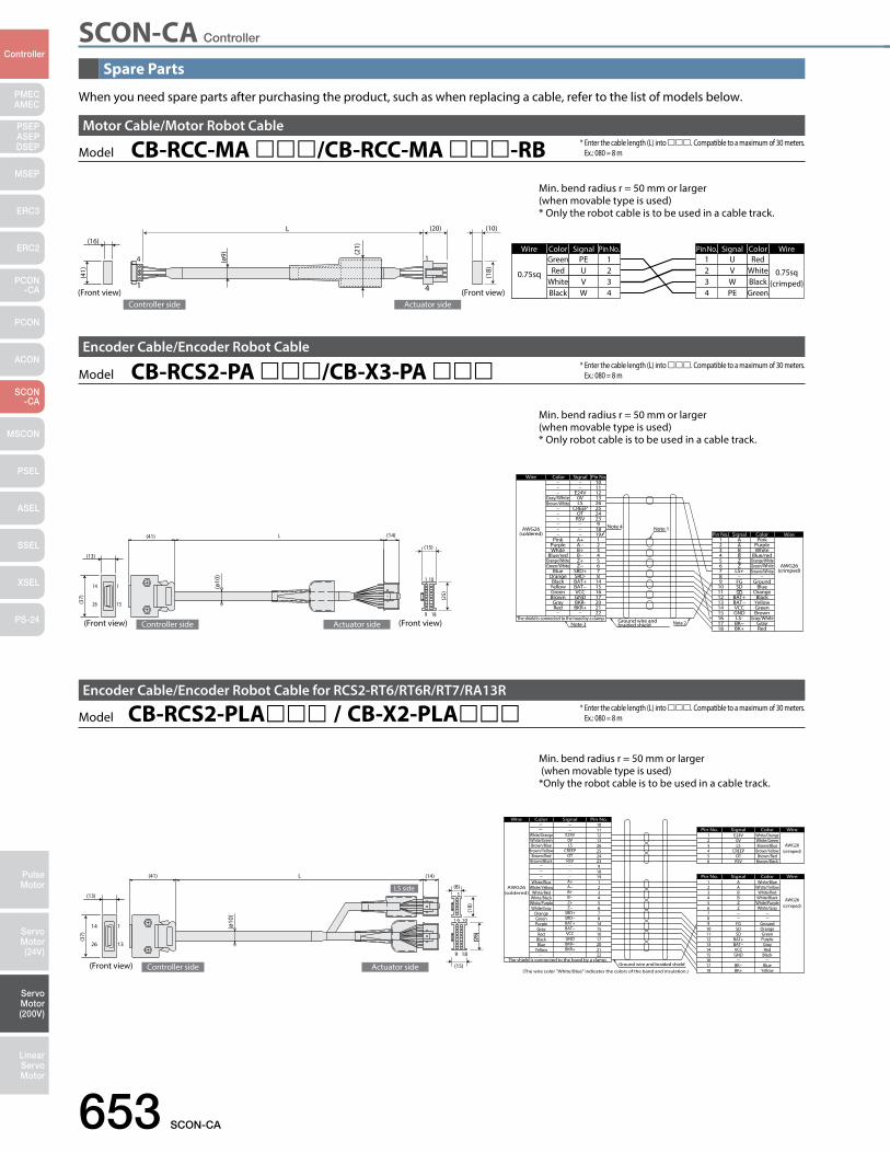
SCON-CA Controller
653 SCON-CA
PMECAMEC
Controller
Pulse Motor
Servo Motor (24V)
Servo Motor (200V)
LinearServo Motor
PSEP ASEPDSEP
MSEP
ERC3
ERC2
PCON-CA
PCON
ACON
SCON-CA
MSCON
PSEL
ASEL
SSEL
XSEL
PS-24
Spare Parts
When you need spare parts after purchasing the product, such as when replacing a cable, refer to the list of models below.
Model CB-RCC-MA /CB-RCC-MA -RBMotor Cable/Motor Robot Cable
L
4
1
1
4
Wire Color Signal Pin No. Pin No.
0.75sq
Green PE 1WireColorSignal
0.75sq(crimped)
RedU1
(10)(20)
Controller side Actuator side(Front view)(Front view)
(16)
(ø9) (2
1)
(18)
(41) U
VW
RedWhiteBlack
234
234
VWPE
WhiteBlackGreen
Model CB-RCS2-PA /CB-X3-PA Encoder Cable/Encoder Robot Cable
1
9
1
13
14
26
18
10
L
Ground wire and braided shield
Note 1
Note 2
Note 4
GrayRed
Brown
YellowGreen
Black
Green/White AWG26(crimped)
Orange
GroundBlue
Blue/redOrange/White
WhitePurple
Pink
15161718
1413121110
6
987
3
54
21
Pin No.
BK−BK+
GNDLS-
BAT+BAT−VCC
Z
FGSDSD
LS+
B
ZB
AA
Signal Color Wire
The shield is connected to the hood by a clamp.Note 3
AWG26(soldered)
Wire
212017
22
6
16151487
3
54
21
25
1819
2324
9
1011121326
Pin No.
BKR+BKR-GND
Z−
BAT+
VCCBAT−
SRD-SRD+
B+
Z+B−
A−A+
CREEPOTRSV
E24V0VLS
Signal
Brown/White
Gray/White
Color
Brown
RedGray
Green/WhiteOrange/White
WhiteBlue/red
Purple
GreenYellowBlack
Blue
Pink
Orange
Brown/WhiteGray/White
(ø10
)
(41) (14)
(13)
(37)
(15)
(25)
Controller side Actuator side (Front view)(Front view)
Min. bend radius r = 50 mm or larger (when movable type is used)* Only robot cable is to be used in a cable track.
Min. bend radius r = 50 mm or larger (when movable type is used)* Only the robot cable is to be used in a cable track.
Model CB-RCS2-PLA / CB-X2-PLAEncoder Cable/Encoder Robot Cable for RCS2-RT6/RT6R/RT7/RA13R
* Enter the cable length (L) into . Compatible to a maximum of 30 meters. Ex.: 080 = 8 m
* Enter the cable length (L) into . Compatible to a maximum of 30 meters. Ex.: 080 = 8 m
* Enter the cable length (L) into . Compatible to a maximum of 30 meters. Ex.: 080 = 8 m
1
9
1
13
14
26
18
10
L
6
1
(ø10
)
Ground wire and braided shield
(crimped)AWG26
AWG26(soldered)
White/Blue
White/Orange
A+
E24V
10
White/BlueA1
Wire Color Signal Pin No.
WireColorSignalPin No.
The shield is connected to the hood by a clamp.
(The wire color "White/Blue" indicates the colors of the band and insulation.)
(crimped)AWG26
White/OrangeE24V1WireColorSignalPin No.
White/YellowWhite/Red
White/BlackWhite/PurpleWhite/Gray
OrangeGreenPurpleGrayRed
BlackBlue
Yellow
White/GreenBrown/Blue
Brown/YellowBrown/Red
Brown/Black
0VLS
CREEPOTRSV
A−B+B−Z+Z−
SRD+SRD−BAT+BAT−VCCGNDBKR−BKR+
111213262524239
181912345678
14151617202122
LS side(13)
(41) (14)
(37)
(8)
(15)
(18)
(25)
23456
23456789
101112131415161718
ABBZZ
FGSDSD
BAT+BAT−VCCGND
BK−BK+
0VLS
CREEPOTRSV
White/GreenBrown/Blue
Brown/YellowBrown/Red
Brown/Black
White/YellowWhite/Red
White/BlackWhite/PurpleWhite/Gray
GroundOrangeGreenPurpleGrayRed
Black
BlueYellowController side Actuator side(Front view)
Min. bend radius r = 50 mm or larger (when movable type is used)*Only the robot cable is to be used in a cable track.
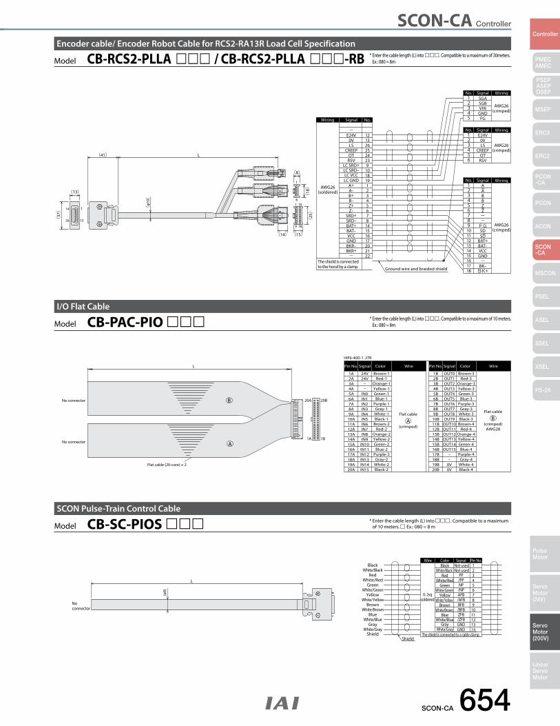
SCON-CA Controller
SCON-CA 654
PMECAMEC
Controller
Pulse Motor
Servo Motor (24V)
Servo Motor (200V)
LinearServo Motor
PSEP ASEPDSEP
MSEP
ERC3
ERC2
PCON-CA
PCON
ACON
SCON-CA
MSCON
PSEL
ASEL
SSEL
XSEL
PS-24
* Enter the cable length (L) into . Compatible to a maximum of 10 meters. Ex.: 080 = 8m
* Enter the cable length (L) into . Compatible to a maximum of 30meters. Ex.: 080 = 8m
ShieldShield
White/GrayGray
White/BlueBlue
White/BrownBrown
White/YellowYellow
White/GreenGreen
White/RedRed
BlackWhite/Black
The shield is connected to a cable clamp.
0. 2sqsoldered
14131211109876543
12
Pin No.Wire
White/GrayGray
White/BlueBlue
White/BrownBrown
White/YellowYellow
White/GreenGreen
White/RedRed
BlackWhite/Black
ColorNot usedNot used
GNDGND/ZFBZFB/BFBBFB/AFBAFB/NPNP/PPPP
Signal
L
No connector
(ø9)
Model CB-SC-PIOS SCON Pulse-Train Control Cable
* Enter the cable length (L) into ccc . Compatible to a maximum of 10 meters. c Ex.: 080 = 8 m
B
BFlat cable
(crimped)
Flat cable
(crimped)AWG28
Flat cable (20-core) × 2
HIF6-40D-1. 27R
20B20A
1B1AA
A
No connector
No connector
Brown-1
ColorL Pin No. Signal Wire
24V Brown-3
ColorPin No. Signal Wire
OUT01A2A3A4A5A6A7A8A9A
10A11A12A13A14A15A16A17A18A19A20A
24V
IN0IN1IN2IN3IN4IN5IN6IN7IN8IN9
IN10IN11IN12IN13IN14IN15
Red-1Orange-1Yellow-1Green-1Blue-1
Purple-1Gray-1
White-1Black-1
Brown-2Red-2
Orange-2Yellow-2Green-2Blue-2
Purple-2Gray-2
White-2Black-2
1B2B3B4B5B6B7B8B9B
10B11B12B13B14B15B16B17B18B19B20B
OUT1OUT2OUT3OUT4OUT5OUT6OUT7OUT8OUT9
OUT10OUT11OUT12OUT13OUT14OUT15
0V0V
Red-3Orange-3Yellow-3Green-3Blue-3
Purple-3Gray-3
White-3Black-3
Brown-4Red-4
Orange-4Yellow-4Green-4Blue-4
Purple-4Gray-4
White-4Black-4
Model CB-PAC-PIO I/O Flat Cable
Model CB-RCS2-PLLA / CB-RCS2-PLLA -RBEncoder cable/ Encoder Robot Cable for RCS2-RA13R Load Cell Specification
Ground wire and braided shield
AWG26(soldered)
Wiring
Wiring
1
9
1
13
14
26
18
106
1
SDSD
OTRSV
0V
CREEPLS
E24V
BK+BK-
GNDVCCBAT-BAT+
FG
AABBZZ--
-
SGBVIN
SGA
FGGND
5
98
67
4321
No.
56
No.
2
43
1
1011121314
18171615
45
1
32
No.
(crimped)AWG26
AWG26(crimped)
AWG26(crimped)
2425
22
26
876
45
3
12
141516172021
23
13
No.
12
1918
910
GND
BAT+BAT-
Signal
Signal
WiringSignal
WiringSignal
VCC
A+A-B+B-Z+Z-
SRD+SRD-
BKR-BKR+-
RSVOT
CREEPLS0V
E24V-
LC SRD+
LC GND
LC SRD-LC VCC
L(41)
(13)
(φ
10)
The shield is connected to the hood by a clamp.
(37)
(8)
(25)
(18)
(15)(14)
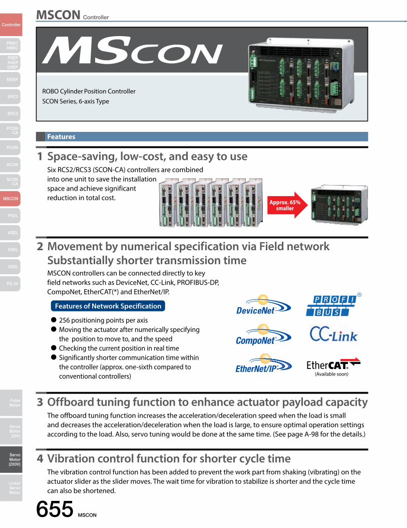
MSCON Controller
655 MSCON
PMECAMEC
Controller
Pulse Motor
Servo Motor (24V)
Servo Motor (200V)
LinearServo Motor
PSEP ASEPDSEP
MSEP
ERC3
ERC2
PCON-CA
PCON
ACON
SCON-CA
MSCON
PSEL
ASEL
SSEL
XSEL
PS-24
ROBO Cylinder Position Controller SCON Series, 6-axis Type
1 Space-saving, low-cost, and easy to use Six RCS2/RCS3 (SCON-CA) controllers are combined into one unit to save the installation space and achieve significant reduction in total cost.
3 Offboard tuning function to enhance actuator payload capacity The offboard tuning function increases the acceleration/deceleration speed when the load is small and decreases the acceleration/deceleration when the load is large, to ensure optimal operation settings according to the load. Also, servo tuning would be done at the same time. (See page A-98 for the details.)
4 Vibration control function for shorter cycle time The vibration control function has been added to prevent the work part from shaking (vibrating) on the actuator slider as the slider moves. The wait time for vibration to stabilize is shorter and the cycle time can also be shortened.
2 Movement by numerical specification via Field network Substantially shorter transmission time MSCON controllers can be connected directly to key field networks such as DeviceNet, CC-Link, PROFIBUS-DP, CompoNet, EtherCAT(*) and EtherNet/IP.
Features
Approx. 65% smaller
Features of Network Specification
256 positioning points per axis Moving the actuator after numerically specifying the position to move to, and the speed Checking the current position in real time Significantly shorter communication time within the controller (approx. one-sixth compared to conventional controllers) (Available soon)
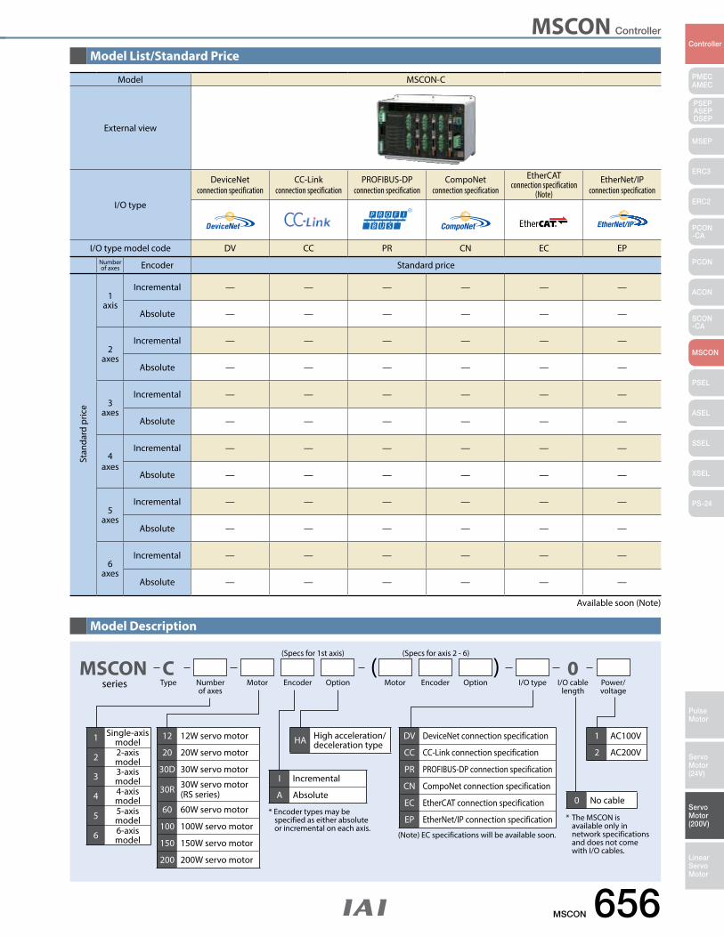
MSCON Controller
MSCON 656
PMECAMEC
Controller
Pulse Motor
Servo Motor (24V)
Servo Motor (200V)
LinearServo Motor
PSEP ASEPDSEP
MSEP
ERC3
ERC2
PCON-CA
PCON
ACON
SCON-CA
MSCON
PSEL
ASEL
SSEL
XSEL
PS-24
MSCONseries
CType
( )Motor MotorNumber
of axesEncoder
(Specs for 1st axis) (Specs for axis 2 - 6)
EncoderOption Option I/O type Power/voltage
0I/O cable
length
DV DeviceNet connection specification
CC CC-Link connection specification
PR PROFIBUS-DP connection specification
CN CompoNet connection specification
EC EtherCAT connection specification
EP EtherNet/IP connection specification
0 No cable
* The MSCON is available only in network specifications and does not come with I/O cables.
* Encoder types may be specified as either absolute or incremental on each axis.
(Note) EC specifications will be available soon.
I Incremental
A Absolute
12 12W servo motor
20 20W servo motor
30D 30W servo motor
30R 30W servo motor(RS series)
60 60W servo motor
100 100W servo motor
150 150W servo motor
200 200W servo motor
1 Single-axis model
2 2-axis model
3 3-axis model
4 4-axis model
5 5-axis model
6 6-axis model
1 AC100V
2 AC200VHA High acceleration/
deceleration type
Model List/Standard Price
Model Description
Available soon (Note)
Model MSCON-C
External view
I/O type
DeviceNet connection specification
CC-Link connection specification
PROFIBUS-DP connection specification
CompoNetconnection specification
EtherCATconnection specification
(Note)
EtherNet/IPconnection specification
I/O type model code DV CC PR CN EC EPNumber of axes Encoder Standard price
1 axis
Incremental — — — — — —
Absolute — — — — — —
2 axes
Incremental — — — — — —
Absolute — — — — — —
3 axes
Incremental — — — — — —
Absolute — — — — — —
4 axes
Incremental — — — — — —
Absolute — — — — — —
5 axes
Incremental — — — — — —
Absolute — — — — — —
6 axes
Incremental — — — — — —
Absolute — — — — — —
Stan
dard
pric
e
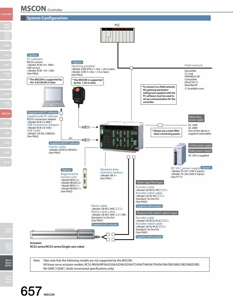
MSCON Controller
657 MSCON
PMECAMEC
Controller
Pulse Motor
Servo Motor (24V)
Servo Motor (200V)
LinearServo Motor
PSEP ASEPDSEP
MSEP
ERC3
ERC2
PCON-CA
PCON
ACON
SCON-CA
MSCON
PSEL
ASEL
SSEL
XSEL
PS-24
ActuatorRCS2 series/RCS3 series/Single-axis robot
Motor cable<Model: CB-RCC-MA>Motor robot cable <Model: CB-RCC-MA-RB>Standard 1m/3m/5m(See P663)
Motor drive power supply
Encoder cable<Model: CB-RCS2-PA>Encoder robot cable<Model: CB-X3-PA>Standard 1m/3m/5m(See P663)
Rotary/Limit switch option type
Slider type/Rod type
Encoder cable<Model: CB-RCS2-PLA>Encoder robot cable <Model: CB-X2-PLA>Standard 1m/3m/5m(See P663)
Field network
PLC
DeviceNetCC-LinkPROFIBUS-DPCompoNetEtherCAT (*)EtherNet/IP(*) Available soon
Absolute data retention battery<Model: AB-5>(See P662 )
* Always use a noise lter when connecting power.
Teaching pendant<Model: CON-PTA-C> (Ver. 1.20 or later)<Model: CON-T>(Ver. 1.13 or later)(See P662)
* The MSCON is supported by Ver. 1.20 or later.
AC 100VAC 200VOne of the above is supplied (selectable)
Control power supply
Brake power supply
DC 24V is supplied
DC 24-C power supply<Model: PS-241 (100-V input)><Model: PS-242 (200-V input)>(See P717)
PC softwareRS232 version <Model: RCM-101- MW>USB version<Model: RCM -101- USB>(See P662)
* The MSCON is supported by Ver. 9.02.00.00 or later.
Option
Option
Regenerative resistor unit<Model RESU-2><Model RESUD-2><Model RESU-1><Model RESUD-1>(See P662)
OptionOption
Supplied with actuator
Supplied with actuator
Supplied with actuator
Supplied with PC softwareRS232 connection adapter <Model: RCB-CV-MW>USB Conversion Adapter<Model: RCB-CV-USB>USB Cable<Model: CB-SEL-USB030>(See P662)
Comm. cable<Model: CB-RCA-SIO050>(See P662)
Supplied with PC software
Supplied with PC software
5m
* To connect to a eld network, the gateway parameter setting tool supplied with the PC software must be used to set up communication for the controller.
Note Take note that the following models are not supported by the MSCON: All linear servo actuator models, RCS2-RN5N/RP5N/GS5N/GD5N/SD5N/TCA5N/TWA5N/TFA5N/SRA7BD/SRGS7BD/SRGD7BD, NS-SXM/SZM (both incremental specifications only)
System Configuration
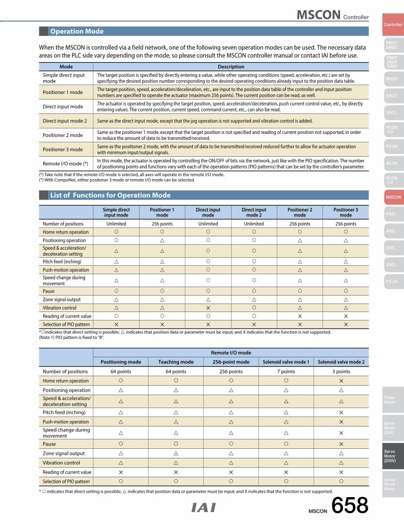
MSCON Controller
MSCON 658
PMECAMEC
Controller
Pulse Motor
Servo Motor (24V)
Servo Motor (200V)
LinearServo Motor
PSEP ASEPDSEP
MSEP
ERC3
ERC2
PCON-CA
PCON
ACON
SCON-CA
MSCON
PSEL
ASEL
SSEL
XSEL
PS-24
When the MSCON is controlled via a field network, one of the following seven operation modes can be used. The necessary data areas on the PLC side vary depending on the mode, so please consult the MSCON controller manual or contact IAI before use.
Remote I/O mode
Positioning mode Teaching mode 256-point mode Solenoid valve mode 1 Solenoid valve mode 2
Number of positions 64 points 64 points 256 points 7 points 3 points
Home return operation
Positioning operation
Speed & acceleration/ deceleration setting
Pitch feed (inching)
Push-motion operation
Speed change during movement
Pause
Zone signal output
Vibration control
Reading of current value
Selection of PIO pattern
Simple direct input mode
Positioner 1 mode
Direct input mode
Direct input mode 2
Positioner 2 mode
Positioner 3 mode
Number of positions Unlimited 256 points Unlimited Unlimited 256 points 256 points
Home return operation
Positioning operation Speed & acceleration/ deceleration setting
Pitch feed (inching)
Push-motion operation Speed change during movement
Pause
Zone signal output
Vibration control
Reading of current value
Selection of PIO pattern
* indicates that direct setting is possible; indicates that position data or parameter must be input; and X indicates that the function is not supported. (Note 1) PIO pattern is fixed to "8".
Mode Description
Simple direct input mode
The target position is specified by directly entering a value, while other operating conditions (speed, acceleration, etc.) are set by specifying the desired position number corresponding to the desired operating conditions already input to the position data table.
Positioner 1 mode The target position, speed, acceleration/deceleration, etc., are input to the position data table of the controller and input position numbers are specified to operate the actuator (maximum 256 points). The current position can be read, as well.
Direct input mode The actuator is operated by specifying the target position, speed, acceleration/deceleration, push current control value, etc., by directly entering values. The current position, current speed, command current, etc., can also be read.
Direct input mode 2 Same as the direct input mode, except that the jog operation is not supported and vibration control is added.
Positioner 2 mode Same as the positioner 1 mode, except that the target position is not specified and reading of current position not supported, in order to reduce the amount of data to be transmitted/received.
Positioner 3 mode Same as the positioner 2 mode, with the amount of data to be transmitted/received reduced further to allow for actuator operation with minimum input/output signals.
Remote I/O mode (*) In this mode, the actuator is operated by controlling the ON/OFF of bits via the network, just like with the PIO specification. The number of positioning points and functions vary with each of the operation patterns (PIO patterns) that can be set by the controller’s parameter.
(*) Take note that if the remote I/O mode is selected, all axes will operate in the remote I/O mode. (*) With CompoNet, either positoner 3 mode or remote I/O mode can be selected.
* indicates that direct setting is possible; indicates that position data or parameter must be input; and X indicates that the function is not supported.
Operation Mode
List of Functions for Operation Mode
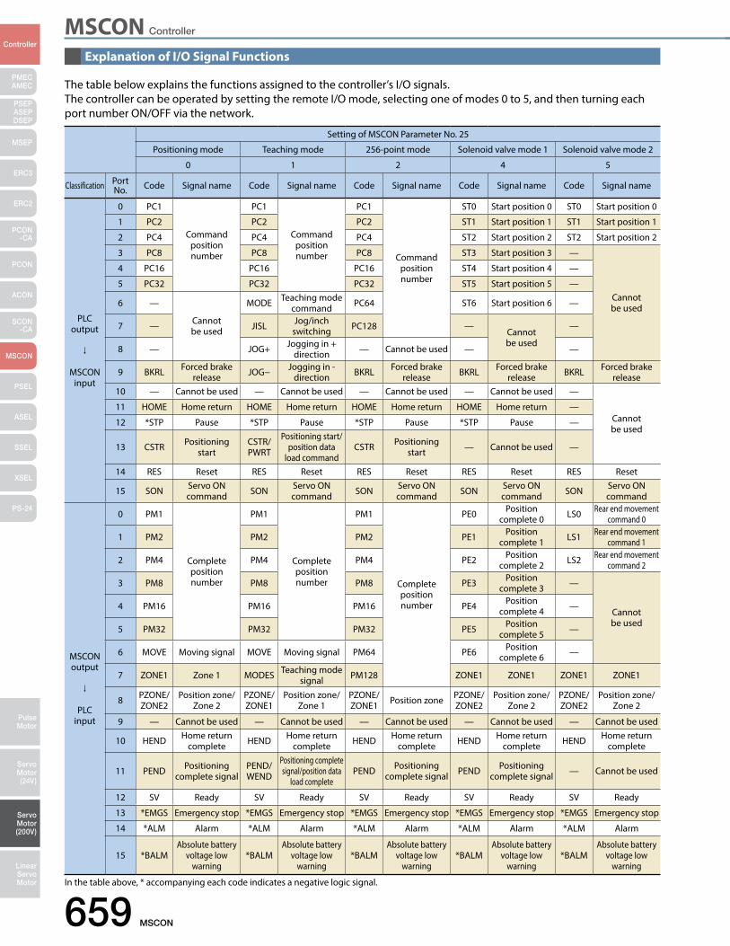
MSCON Controller
659 MSCON
PMECAMEC
Controller
Pulse Motor
Servo Motor (24V)
Servo Motor (200V)
LinearServo Motor
PSEP ASEPDSEP
MSEP
ERC3
ERC2
PCON-CA
PCON
ACON
SCON-CA
MSCON
PSEL
ASEL
SSEL
XSEL
PS-24
Setting of MSCON Parameter No. 25
Positioning mode Teaching mode 256-point mode Solenoid valve mode 1 Solenoid valve mode 2
0 1 2 4 5
Classification Port No. Code Signal name Code Signal name Code Signal name Code Signal name Code Signal name
PLC output
MSCON input
0 PC1
Command position number
PC1
Command position number
PC1
Command position number
ST0 Start position 0 ST0 Start position 0
1 PC2 PC2 PC2 ST1 Start position 1 ST1 Start position 1
2 PC4 PC4 PC4 ST2 Start position 2 ST2 Start position 2
3 PC8 PC8 PC8 ST3 Start position 3 —
Cannot be used
4 PC16 PC16 PC16 ST4 Start position 4 —
5 PC32 PC32 PC32 ST5 Start position 5 —
6 —
Cannot be used
MODE Teaching mode command PC64 ST6 Start position 6 —
7 — JISL Jog/inch switching PC128 —
Cannot be used
—
8 — JOG+ Jogging in + direction — Cannot be used — —
9 BKRL Forced brake release JOG− Jogging in -
direction BKRL Forced brake release BKRL Forced brake
release BKRL Forced brake release
10 — Cannot be used — Cannot be used — Cannot be used — Cannot be used —
Cannot be used
11 HOME Home return HOME Home return HOME Home return HOME Home return —
12 *STP Pause *STP Pause *STP Pause *STP Pause —
13 CSTR Positioning start
CSTR/PWRT
Positioning start/position data
load commandCSTR Positioning
start — Cannot be used —
14 RES Reset RES Reset RES Reset RES Reset RES Reset
15 SON Servo ON command SON Servo ON
command SON Servo ON command SON Servo ON
command SON Servo ON command
MSCON output
PLC input
0 PM1
Complete position number
PM1
Complete position number
PM1
Complete position number
PE0 Position complete 0 LS0 Rear end movement
command 0
1 PM2 PM2 PM2 PE1 Position complete 1 LS1 Rear end movement
command 1
2 PM4 PM4 PM4 PE2 Position complete 2 LS2 Rear end movement
command 2
3 PM8 PM8 PM8 PE3 Position complete 3 —
Cannot be used
4 PM16 PM16 PM16 PE4 Position complete 4 —
5 PM32 PM32 PM32 PE5 Position complete 5 —
6 MOVE Moving signal MOVE Moving signal PM64 PE6 Position complete 6 —
7 ZONE1 Zone 1 MODES Teaching mode signal PM128 ZONE1 ZONE1 ZONE1 ZONE1
8 PZONE/ZONE2
Position zone/Zone 2
PZONE/ZONE1
Position zone/Zone 1
PZONE/ZONE1 Position zone PZONE/
ZONE2Position zone/
Zone 2PZONE/ZONE2
Position zone/Zone 2
9 — Cannot be used — Cannot be used — Cannot be used — Cannot be used — Cannot be used
10 HEND Home return complete HEND Home return
complete HEND Home return complete HEND Home return
complete HEND Home return complete
11 PEND Positioning complete signal
PEND/WEND
Positioning complete signal/position data
load completePEND Positioning
complete signal PEND Positioning complete signal — Cannot be used
12 SV Ready SV Ready SV Ready SV Ready SV Ready
13 *EMGS Emergency stop *EMGS Emergency stop *EMGS Emergency stop *EMGS Emergency stop *EMGS Emergency stop
14 *ALM Alarm *ALM Alarm *ALM Alarm *ALM Alarm *ALM Alarm
15 *BALMAbsolute battery
voltage low warning
*BALMAbsolute battery
voltage low warning
*BALMAbsolute battery
voltage low warning
*BALMAbsolute battery
voltage low warning
*BALMAbsolute battery
voltage low warning
The table below explains the functions assigned to the controller’s I/O signals.The controller can be operated by setting the remote I/O mode, selecting one of modes 0 to 5, and then turning each port number ON/OFF via the network.
In the table above, * accompanying each code indicates a negative logic signal.
Explanation of I/O Signal Functions
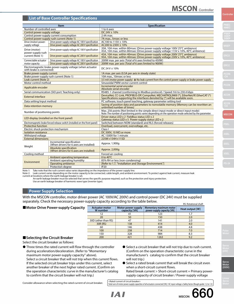
MSCON Controller
MSCON 660
PMECAMEC
Controller
Pulse Motor
Servo Motor (24V)
Servo Motor (200V)
LinearServo Motor
PSEP ASEPDSEP
MSEP
ERC3
ERC2
PCON-CA
PCON
ACON
SCON-CA
MSCON
PSEL
ASEL
SSEL
XSEL
PS-24
With the MSCON controller, motor driver power (AC 100V/AC 200V) and control power (DC 24V) must be supplied separately. Check the necessary power-supply capacity according to the table below.
Motor Drive Power-supply Capacity
Selecting the Circuit Breaker Select the circuit breaker as follows:
Item SpecificationNumber of controlled axes 1 to 6 axesControl power-supply voltage DC 24V ± 10%Control power-supply current consumption 2.4A max.Control power-supply rush current (Note 1) 7A max., 5msec or lessDrive (motor) power-supply voltage
Drive power-supply voltage AC 100 V specification AC100 to 115V ± 10%Drive power-supply voltage AC 200 V specification AC200 to 230V ± 10%
Drive (motor) power-supply rush current (Note 1)
Drive power-supply voltage AC 100 V specification 20A, 10A max. within 80msec (Drive power-supply voltage 100V 25°C ambience)45A, 10A max. within 80msec (Drive power-supply voltage 115V x 10%, 40°C ambience)
Drive power-supply voltage AC 200 V specification 45A, 10A max. within 40msec (Drive power-supply voltage 200V 25°C ambience)95A, 10A max. within 40msec (Drive power-supply voltage 230V x 10%, 40°C ambience)
Connectable actuator motor capacity
Drive power-supply voltage AC 100 V specification 200W max. per axis (Total of 6 axes limited to 450W)Drive power-supply voltage AC 200 V specification 200W max. per axis (Total of 6 axes limited to 900W)
Electromagnetic brake power-supply voltage (when actuator with brake is connected) DC 24 V ± 10%
Brake power-supply current 1A max. per axis (0.5A per axis in steady state)Brake power-supply rush current (Note 1) 10A max., 10msec or lessLeak current (Note 2) 3.5 mA (motor power supply) No leak current from the control power supply or brake power supply Motor control method Sinusoidal PWM vector current control
Applicable encoder Incremental serial encoder Absolute serial encoder
Serial communication (SIO port: Teaching only) RS485: 1 channel (conforming to Modbus protocol) / Speed: 9.6 to 230.4 kbps
External interface DeviceNet, CC-Link, PROFIBUS-DP, CompoNet, MECHATROLINKII (*), EtherNet/IP, EtherCAT (*)Specifications supporting the interfaces denoted by (*) will be available soon.
Data setting/input method PC software, touch panel teaching, gateway parameter setting tool
Data retention memory Saving of position data and parameters to nonvolatile memory (Memory can be rewritten an unlimited number of times)
Number of positioning points Max. 256 points (Not limited in the simple direct input mode or direct input mode)Note: The number of positioning points varies depending on the operation mode selected by the parameter.
LED display (installed on the front panel) Driver status LED x 2 Fieldbus status LED x 2Gateway status LED x 5 Power-supply status LED x 2
Electromagnetic brake forced release switch (installed on the front panel) Switched between NOM (standard) and RLS (forced releases)Protective function Overload, overcurrent, overvoltage, etc.Electric shock protection mechanism Class IIsolation resistance DC 500V, 10 MΩ or moreWithstand voltage AC 1500V for 1 minuteExternal dimensions 225W×154H×115D
Weight
Incremental specification (When drivers for 6 axes are installed) Approx. 1,900g
Absolute specification(When drivers for 6 axes are installed) Approx. 2,000g
Cooling method Forced air cooling
Environment
Ambient operating temperature 0 to 40°CAmbient operating humidity 85% RH or less (non-condensing)Operating ambience [Refer to 1.7, "Installation and Storage Environment."]Protection degree IP20
Note 1: Take note that the rush current value varies depending on the impedance of the power supply line.Note 2: Leak current varies depending on the motor capacity to be connected, cable length, and ambient environment. To protect against leak current, measure leak current at locations where the earth leakage breaker is set. An earth leakage breaker must be selected that serves the specific purpose required, such as fire protection and injury protection. Use an earth leakage breaker of harmonic wave type (inverter type).
List of Base Controller Specifications
Power Supply Selection
Actuator motor W number
Motor power supply capacity [VA]
Momentary maximum motor power-supply capacity [VA] Heat output [W]
12 41 123 1.720 50 150 2.0
30D (other than RS) 47 141 2.030R (RS) 138 414 4.0
60 146 438 4.8100 238 714 7.0150 328 984 8.3200 421 1263 9.2
RS: Rotational shaft
Three times the rated current will flow through the controller during acceleration/deceleration. (Refer to "Momentary maximum motor power-supply capacity" above).
Select a circuit breaker that will not trip when this current flows. If the selected circuit breaker trips under this current, select another breaker of the next higher rated current. (Confirm on the operation characteristic curve in the manufacturer’s catalog to confirm that the circuit breaker will not trip.)
Select a circuit breaker that will not trip due to rush current. (Confirm on the operation characteristic curve in the manufacturer’s catalog to confirm that the circuit breaker will not trip.)
Select a rated break current that will break the circuit even when a short-circuit current flows.
Rated break current > Short-circuit current = Primary power-supply capacity of circuit breaker / Power-supply voltage
<Rated current of circuit breaker> Total sum of motor power-supply capacities of all actuators connected [VA] / AC input voltage x Safety factor (Rough guide: 1.2 to 1.3)Consider allowance when selecting the rated current of circuit breaker.

MSCON Controller
661 MSCON
PMECAMEC
Controller
Pulse Motor
Servo Motor (24V)
Servo Motor (200V)
LinearServo Motor
PSEP ASEPDSEP
MSEP
ERC3
ERC2
PCON-CA
PCON
ACON
SCON-CA
MSCON
PSEL
ASEL
SSEL
XSEL
PS-24
Control Power-supply (DC 24-V) Capacity Calculate the DC 24-V power-supply capacity as follows: (1) Current consumption of control power supply: Select the applicable control power-supply current shown in the table below --- ➀
(3) Rush current of control power supply: 7 A/ --- ➂ [Selection of power supply] Normally a power supply whose rated current is approx. 1.3 times is selected by considering approx. 30% of allowance on top of the load current of ➀ + ➁ above. Since the current of ➂ will flow for a short period, select a power supply of the "peak load accommodation" specification or having enough allowance. If the selected power supply has no allowance, voltage may drop momentarily. In particular, pay attention to the power supply with remote sensing function.
(2) Current consumption of brake power supply: 1 A or 0.5 A (Note 2) x Number of actuators with brakes --- ➁ (Note 2): When the brake is released, up to 1 A of current will flow per actuator for a period of approx. 100 ms. If this maximum current can be accommodated by the DC 24-V power supply used which is capable of handling momentary load fluctuation at the time of peak load, etc., calculate at 0.5 A/unit. If not, calculate at 1 A/unit.
Number of controlled axes (Note 1) 1 axis 2 axes 3 axes 4 axes 5 axes 6 axesHeat generation from control
power supply [W] 25.5 31.5 38.2 44.2 50.9 56.9
Control power-supply current [A] 1.1 1.3 1.6 1.8 2.1 2.4
(Note 1): Check the maximum number of controlled axes that can be connected to the MSCON. This information is available on the manufacturer’s nameplate. MSCON-C-*-…: * represents the maximum number of axes that can be connected.
225
10.5 2045 5
154
4.5
145
10.5 102 102
115
(77
mm
from
the
cent
er o
f the
DIN
rail)
4
3-ø5
(9)
10.5
10.5
913
6
4.5
10.5
10.5
9
4
Incremental specification
225
10.5 2045 5
154
4.5
145
10.5 102 102
4
3-ø5
4
10.5
10.5
99
136
4.5
10.5
10.5
115
(134)
(22.
3)
(77
mm
from
the
cent
er o
f the
DIN
rail)
(9)
Absolute specification
External Dimensions
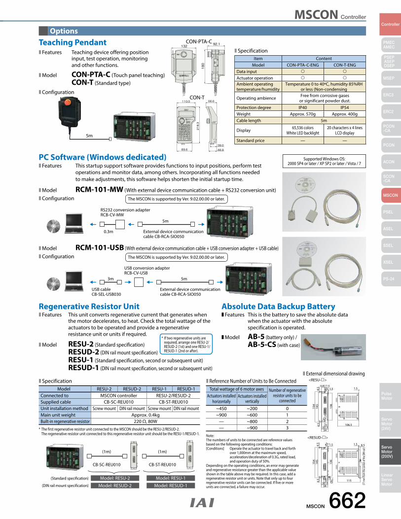
MSCON Controller
MSCON 662
PMECAMEC
Controller
Pulse Motor
Servo Motor (24V)
Servo Motor (200V)
LinearServo Motor
PSEP ASEPDSEP
MSEP
ERC3
ERC2
PCON-CA
PCON
ACON
SCON-CA
MSCON
PSEL
ASEL
SSEL
XSEL
PS-24
PC Software (Windows dedicated)
Features This is the battery to save the absolute data when the actuator with the absolute specification is operated.
Model AB-5 (battery only) / AB-5-CS (with case)
Absolute Data Backup Battery
RS232 conversion adapterRCB-CV-MW
External device communication cable CB-RCA-SIO050
0.3m
5m
USB conversion adapterRCB-CV-USB
External device communication cable CB-RCA-SIO050
USB cableCB-SEL-USB030
5m3m
Features This startup support software provides functions to input positions, perform test operations and monitor data, among others. Incorporating all functions needed to make adjustments, this software helps shorten the initial startup time.
Model RCM-101-MW (With external device communication cable + RS232 conversion unit)Configuration The MSCON is supported by Ver. 9.02.00.00 or later.
Model RCM-101-USB (With external device communication cable + USB conversion adapter + USB cable)Configuration The MSCON is supported by Ver. 9.02.00.00 or later.
Features This unit converts regenerative current that generates when the motor decelerates, to heat. Check the total wattage of the actuators to be operated and provide a regenerative resistance unit or units if required.
Model RESU-2 (Standard specification) RESUD-2 (DIN rail mount specification) RESU-1 (Standard specification, second or subsequent unit) RESUD-1 (DIN rail mount specification, second or subsequent unit)
Regenerative Resistor Unit
* If two regenerative units are required, arrange one RESU-2/ RESUD-2 (1st) and one RESU-1/ RESUD-1 (2nd or after).
* The first regenerative resistor unit connected to the MSCON should be the RESU-2/RESUD-2. The regenerative resistor unit connected to this regenerative resistor unit should be the RESU-1/RESUD-1. Note:
The numbers of units to be connected are reference values based on the following operating conditions: [Conditions] Operate the actuator to travel back and forth over 1,000mm at the maximum speed, acceleration/deceleration of 0.3G, rated load, and operation duty of 50%. Depending on the operating conditions, an error may generate and regenerative resistance greater than the applicable value shown in the table above may be required. In this case, add a regenerative resistor unit or units. Note that only up to four regenerative resistor units can be connected. If five or more units are connected, a failure may occur.
Reference Number of Units to Be ConnectedExternal dimensional drawing
Model RESU-2 RESUD-2 RESU-1 RESUD-1Connected to MSCON controller RESU-2/RESUD-2Supplied cable CB-SC-REU010 CB-ST-REU010Unit installation method Screw mount DIN rail mount Screw mount DIN rail mountMain unit weight Approx. 0.4kgBuilt-in regenerative resistor 220 Ω, 80W
Total wattage of 6 motor axes Number of regenerative resistor units to be
connectedActuators installed
horizontallyActuators installed
vertically~450 ~200 0~900 ~600 1
— ~800 2— ~900 3
106.5
1.5
145
154
136
ø5
5
3430.7
4.5
4.5 1.5
R2.5
16.8517.15
(77 m
m fr
om th
e cen
ter o
f the
DIN
rail)
115
4
1.5 8.5
145
154
136
ø5
5
3430.74.
54.
5
(9)
4
1.5
<RESU->
<RESUD->
CB-SC-REU010
(1m)
Model: RESU-2 Model: RESU-1(Standard specification)
(DIN rail mount specification) Model: RESUD-2 Model: RESUD-1
CB-ST-REU010
(1m)
Specification
Features Teaching device offering position input, test operation, monitoring and other functions.
Model CON-PTA-C (Touch panel teaching) CON-T (Standard type)
Configuration
Teaching Pendant
5m
Options
SpecificationItem Content
Model CON-PTA-C-ENG CON-T-ENGData input
Actuator operation
Ambient operating temperature/humidity
Temperature 0 to 40ºC, humidity 85%RH or less (Non-condensing
Operating ambience Free from corrosive gases or significant powder dust.
Protection degree IP40 IP54Weight Approx. 570g Approx. 400gCable length 5m
Display 65,536 colorsWhite LED backlight
20 characters x 4 linesLCD display
Standard price — —
132 92.1
180
CON-PTA-C
CON-T
Supported Windows OS: 2000 SP4 or later / XP SP2 or later / Vista / 7
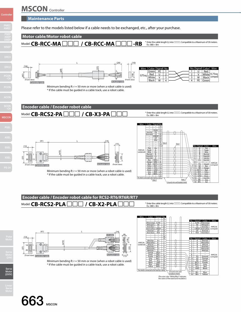
MSCON Controller
663 MSCON
PMECAMEC
Controller
Pulse Motor
Servo Motor (24V)
Servo Motor (200V)
LinearServo Motor
PSEP ASEPDSEP
MSEP
ERC3
ERC2
PCON-CA
PCON
ACON
SCON-CA
MSCON
PSEL
ASEL
SSEL
XSEL
PS-24
Controller side
LS side(13)
(14)(8)
(15)
(41)
(37)
(25)
(18)
(Front view) Actuator side
1
13
14
26
L
6 101
1
9 18
(ø10
)
Ground wire and braided shield
AWG26(crimped)
AWG26 (soldered)
−−
White/orangeWhite/greenBrown/blue
Brown/yellowBrown/red
Brown/black−−−
White/blueWhite/yellow
White/redWhite/black
White/purpleWhite/grayOrangeGreenPurpleGrayRed
BlackBlue
Yellow−
−−
E24V0VLS
CREEPOTRSV
−−−
A+A−B+B−Z+Z−
SRD+SRD−BAT+BAT−VCCGNDBKR−BKR+
−
10111213262524239
181912345678
14151617202122
White/blueWhite/yellow
White/redWhite/black
White/purpleWhite/gray
−−
GroundOrangeGreenPurpleGrayRed
Black−
BlueYellow
AABBZZ−−
FGSDSD
BAT+BAT−VCCGND
−BK−BK+
123456789
101112131415161718
Wire Color Signal No.
WireColorSignalNo.
The shield is connected to the hood by a clamp.
(The wire color "White/Blue" indicates the colors of the band and insulation.)
AWG26(crimped)
White/orangeWhite/greenBrown/blue
Brown/yellowBrown/red
Brown/black
E24V0VLS
CREEPOTRSV
123456
WireColorSignalNo.
Minimum bending R: r = 50 mm or more (when a robot cable is used)* If the cable must be guided in a cable track, use a robot cable.
(41) (14)(15)
Controller side
(13)
(37)
(Front view) (Front view)
(25)
Actuator side
13
114
26
Ground wire and braided shieldNote 2
Note 1Note 4
AWG26(crimped)
PinkPurpleWhite
Blue/redOrange/whiteGreen/whiteBrown/white
–Ground
BlueOrange
BlackYellowGreenBrown
Gray/whiteGrayRed
No. Signal Color Wire
The shield is connected to the hood by a clamp.Note 3
AWG26 (soldered)
Wire10111213262524239
181912345678
14151617202122
123456789
101112131415161718
AĀBBZZ
LS+–
FGSDSD
BAT+BAT-VCCGNDLS-BK-BK+
––
E24VOVLS
CREEPOTRSV
–––
A+A-B+B-Z+Z-
SRD+SRD-BAT+BAT-VCCGNDBKR-BKR+
–
–––
Gray/whiteBrown/white
––––––
PinkPurpleWhite
Blue/redOrange/whiteGreen/white
BlueOrange
BlackYellowGreenBrownGrayRed–
No.SignalColor
(ø10
)
L
1
9 18
10
L
Controller side
4
1
1
4
Wire Color No.
0.75sqGreen
RedWhiteBlack
PEUVW
1234
WireColorSignalNo.
0.75sq (crimped)
RedWhiteBlackGreen
UVWPE
1234Actuator side
(10)(20)
(Front view)(Front view)
(16)
(ø9) (2
1)
(18)
(41)
Signal
Please refer to the models listed below if a cable needs to be exchanged, etc., after your purchase.
Model: CB-RCC-MA / CB-RCC-MA -RBMotor cable/Motor robot cable
* Enter the cable length (L) into . Compatible to a Maximum of 30 meters. Ex.: 080 = 8m
* Enter the cable length (L) into . Compatible to a Maximum of 30 meters. Ex.: 080 = 8m
* Enter the cable length (L) into . Compatible to a Maximum of 30 meters. Ex.: 080 = 8m
Model: CB-RCS2-PA / CB-X3-PAEncoder cable / Encoder robot cable
Model: CB-RCS2-PLA / CB-X2-PLAEncoder cable / Encoder robot cable for RCS2-RT6/RT6R/RT7
Minimum bending R: r = 50 mm or more (when a robot cable is used)* If the cable must be guided in a cable track, use a robot cable.
Minimum bending R: r = 50 mm or more (when a robot cable is used)* If the cable must be guided in a cable track, use a robot cable.
Maintenance Parts
MSCON Controller
MSCON 664
PMECAMEC
Controller
Pulse Motor
Servo Motor (24V)
Servo Motor (200V)
LinearServo Motor
PSEP ASEPDSEP
MSEP
ERC3
ERC2
PCON-CA
PCON
ACON
SCON-CA
MSCON
PSEL
ASEL
SSEL
XSEL
PS-24
MEMO
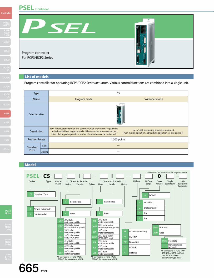
PSEL Controller
665 PSEL
PMECAMEC
Controller
Pulse Motor
Servo Motor (24V)
Servo Motor (200V)
LinearServo Motor
PSEP ASEPDSEP
MSEP
ERC3
ERC2
PCON-CA
PCON
ACON
SCON-CA
MSCON
PSEL
ASEL
SSEL
XSEL
PS-24
List of models
Program controller for operating RCP3/RCP2 Series actuators. Various control functions are combined into a single unit.
PSELSeries
* 2nd axis specs not applicable to the single-axis model.
CS Standard Type
B Brake B Brake
20P
20SP
20 pulse motor-compatible
28P 28 pulse motor-compatible
20 pulse motor (RCP3-RA2 high-thrust type only)
28SP28 pulse motor(RCP2-RA3C only)
42P 42 pulse motor-compatible
35P 35 pulse motor-compatible
56P 56 pulse motor-compatible
20P 20 pulse motor-compatible
28P 28 pulse motor-compatible
20SP 20 pulse motor(RCP3-RA2 high-thrust type only)
28SP 28 pulse motor(RCP2-RA3C only)
42P 42 pulse motor-compatible
35P 35 pulse motor-compatible
56P 56 pulse motor-compatible
1 Single-axis model
2 2-axis model
I Incremental I Incremental
NP PIO NPN (standard)
PN PIO PNP
DV DeviceNet
CC CC-Link
PR ProBus
0 DC24V
0 No cable
2 2m (standard)
3 3m
5 5m
Blank Not used
ABU Used
0CS I I
* If connecting to RCP2-RA3C/ RGD3C, the motor type is 28SP.
* If connecting to RCP2-RA3C/ RGD3C, the motor type is 28SP.
Blank Standard
H High acceleration type model
* If connecting to RCP3-SA4/ SA5/SA6 or RCP2-SA5/SA6, specify "H", for high- acceleration type model.
Type Number of Axes Motor Encoder Option Motor Encoder Option
I/O Cable Length
PowerVoltage
Simple absolute unit
High acceleration type model
I/O Type(Specs for 1st axis) (Specs for 2nd axis)
Model
Program controller For RCP3/RCP2 Series
Type CS
Name Program mode Positioner mode
External view
DescriptionBoth the actuator operation and communication with external equipment can be handled by a single controller. When two axes are connected, arc interpolation, path operations, and synchronization can be performed.
Up to 1,500 positioning points are supported. Push-motion operation and teaching operation are also possible.
Position Points 1,500 points
Standard Price
1 axis —
2 axes —
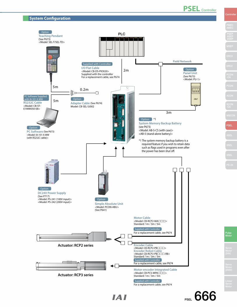
PSEL Controller
PSEL 666
PMECAMEC
Controller
Pulse Motor
Servo Motor (24V)
Servo Motor (200V)
LinearServo Motor
PSEP ASEPDSEP
MSEP
ERC3
ERC2
PCON-CA
PCON
ACON
SCON-CA
MSCON
PSEL
ASEL
SSEL
XSEL
PS-24
OptionPanel Unit(See P673)<Model: PU-1>
2m
0.2m
3m
5m
5m
PLC
Option
Adapter Cable (See P674)Model: CB-SEL-SJ002
Field Network
Actuator: RCP2 series
Actuator: RCP3 series
OptionTeaching Pendant (See P673)<Model: SEL-T/SEL-TD>
Supplied with Controller
I/O Flat Cable<Model: CB-DS-PIO020>Supplied with the controllerFor a replacement cable, see P674
OptionPC Software (See P673)<Model: IA-101-X-MW (with RS232C cable)>
PC Software Suppliedwith IA-101-X-MW
RS232C Cable <Model: CB-ST- E1MW050-EB>
*1 The system memory backup battery is a required feature if you wish to retain data such as flags used in programs even after the power has been shut off.
System Memory Backup Battery (see P673)<Model: AB-5-CS (with case)><AB-5 (stand-alone battery)>
*1Option
DC24V Power Supply(See P717) <Model: PS-241 (100V input)><Model: PS-242 (200V input)>
Option
Simple Absolute Unit<Model: PCON-ABU>(See P641)
Option
Motor Cable<Model: CB-RCP2-MA>Standard: 1m / 3m / 5m
For a replacement cable, see P674Supplied with Controller
Encoder Cable<Model: CB-RCP2-PB>Encoder Robot Cable<Model: CB-RCP2-PB-RB>Standard: 1m / 3m / 5m
For a replacement cable, see P674Supplied with Controller
Motor-encoder Integrated Cable<Model: CB-PCS-MPA>Standard: 1m / 3m / 5m
For a replacement cable, see P674Supplied with Controller
System Configuration
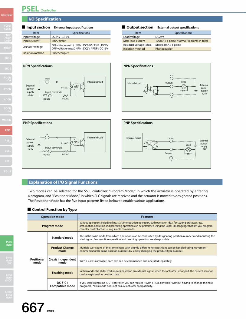
PSEL Controller
667 PSEL
PMECAMEC
Controller
Pulse Motor
Servo Motor (24V)
Servo Motor (200V)
LinearServo Motor
PSEP ASEPDSEP
MSEP
ERC3
ERC2
PCON-CA
PCON
ACON
SCON-CA
MSCON
PSEL
ASEL
SSEL
XSEL
PS-24
Two modes can be selected for the SSEL controller: “Program Mode,” in which the actuator is operated by entering a program, and “Positioner Mode,” in which PLC signals are received and the actuator is moved to designated positions. The Positioner Mode has the five input patterns listed below to enable various applications.
P24V
R=3.3kΩInputs
R=560ΩExternal power supply+24V
Input terminals
Internal circuit
NPN Specifications
P24
N
OutputsInternal circuit LoadExternal power supply+24V
NPN Specifications
N
R=3.3kΩInputs
R=560Ω
External power supply+24V Input terminals
Internal circuit
PNP Specifications
P24V
N
Outputs
Internal circuitExternal power supply+24V
Load
PNP Specifications
I/O Specification
Explanation of I/O Signal Functions
Input section External input specifications Output section External output specifications
Item SpecificationsInput voltage DC24V ±10%Input current 7mA/circuit
ON/OFF voltage ON voltage (min.) NPN : DC16V / PNP : DC8VOFF voltage (max.) NPN : DC5V / PNP : DC19V
Isolation method Photocoupler
Item SpecificationsLoad Voltage DC24VMax. load current 100mA / 1 point 400mA / 8 points in totalResidual voltage (Max.) Max 0.1mA / 1 pointIsolation method Photocoupler
Control Function by Type
Operation mode Features
Program modeVarious operations including linear/arc interpolation operation, path operation ideal for coating processes, etc., arch-motion operation and palletizing operation can be performed using the Super SEL language that lets you program complex control actions using simple commands.
Positioner mode
Standard mode This is the basic mode from which operations can be conducted by designating position numbers and inputting the start signal. Push-motion operation and teaching operation are also possible.
Product Change mode
Multiple work parts of the same shape with slightly different hole positions can be handled using movement commands to the same position numbers by simply changing the product type number.
2-axis independent mode With a 2-axis controller, each axis can be commanded and operated separately.
Teaching mode In this mode, the slider (rod) moves based on an external signal, when the actuator is stopped, the current location can be registered as position data.
DS-S-C1Compatible mode
If you were using a DS-S-C1 controller, you can replace it with a PSEL controller without having to change the host programs. *This mode does not ensure actuator compatibility.
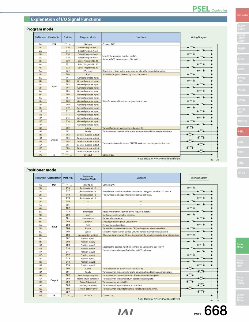
PSEL Controller
PSEL 668
PMECAMEC
Controller
Pulse Motor
Servo Motor (24V)
Servo Motor (200V)
LinearServo Motor
PSEP ASEPDSEP
MSEP
ERC3
ERC2
PCON-CA
PCON
ACON
SCON-CA
MSCON
PSEL
ASEL
SSEL
XSEL
PS-24
Explanation of I/O Signal Functions
Pin Number Classication
Input
Output
N
24V input Connect 24V.
Program Mode Functions
Resets the system to the same state as when the power is turned on.
Turns o when an alarm occurs. (Contact B)Turns on when the controller starts up normally and is in an operable state.
Connect 0V.
These outputs can be turned ON/OFF as desired via program instructions.
Starts the program selected by ports 016 to 022.
Waits for external input via program instructions.
Selects the program number to start. (Input as BCD values to ports 016 to 022)
0V 24
Wiring Diagram
1A P241B2A2B3A3B4A4B5A5B6A6B7A7B8A8B9A9B
10A10B11A11B12A12B13A13B14A14B15A15B16A16B17A17B
016
Port No.
017018019020021022023000001002003004005006007008009010011012013014015300301302303304305306307
Select Program No. 1Select Program No. 2Select Program No. 4Select Program No. 8
Select Program No. 10Select Program No. 20Select Program No. 40
CPU resetStart
General-purpose inputGeneral-purpose inputGeneral-purpose inputGeneral-purpose inputGeneral-purpose inputGeneral-purpose inputGeneral-purpose inputGeneral-purpose inputGeneral-purpose inputGeneral-purpose inputGeneral-purpose inputGeneral-purpose inputGeneral-purpose inputGeneral-purpose inputGeneral-purpose input
AlarmReady
General-purpose outputGeneral-purpose outputGeneral-purpose outputGeneral-purpose outputGeneral-purpose outputGeneral-purpose output
0V input
Program mode
Note: This is for NPN. PNP will be different.
Pin Number
24V input Connect 24V.
——
—
PositionerStandard Mode Functions
Resets minor errors. (Severe errors require a restart.)
Turns o when an alarm occurs. (Contact B)Turns on when the controller starts up normally and is in an operable state.Turns on when the movement to the destination is complete.Turns on when the home return operation is complete.Turns on when servo is ON.Turns on when a push motion is complete.Turns on when the system battery runs low (warning level).
Connect 0V.
Starts moving to selected position.Performs home return.Switches between Servo ON and OFF.Performs a push motion.Pauses the motion when turned OFF, and resumes when turned ON.Stops the motion when turned OFF. The remaining motion is canceled.When this signal is turned ON for a 2-axis model, the actuator moves by linear interpolation.
Species the position numbers to move to, using ports 007 to 019. The number can be specied either as BCD or binary.
Species the position numbers to move to, using port number 007 to 019. The number can be specied either as BCD or binary.
0V 24
Wiring Diagram
1A1B2A2B3A3B4A4B5A5B6A6B7A7B8A8B9A9B
10A10B11A11B12A12B13A13B14A14B15A15B16A16B17A17B
Position input 10Position input 11Position input 12Position input 13
Error resetStart
Home returnServo ON
PushPauseCancel
Interpolation settingsPosition input 1Position input 2Position input 3Position input 4Position input 5Position input 6Position input 7Position input 8Position input 9
AlarmReady
Positioning completeHome return complete
Servo ON outputPushing complete
System battery error
0V input
Classification
Input
Output
N
P24016
Port No.
017
018
019
020
021
022
023
000
001
002
003
004
005
006
007
008
009
010
011
012
013
014
015
300
301
302
303
304
305
306
307
Positioner mode
Note: This is for NPN. PNP will be different.
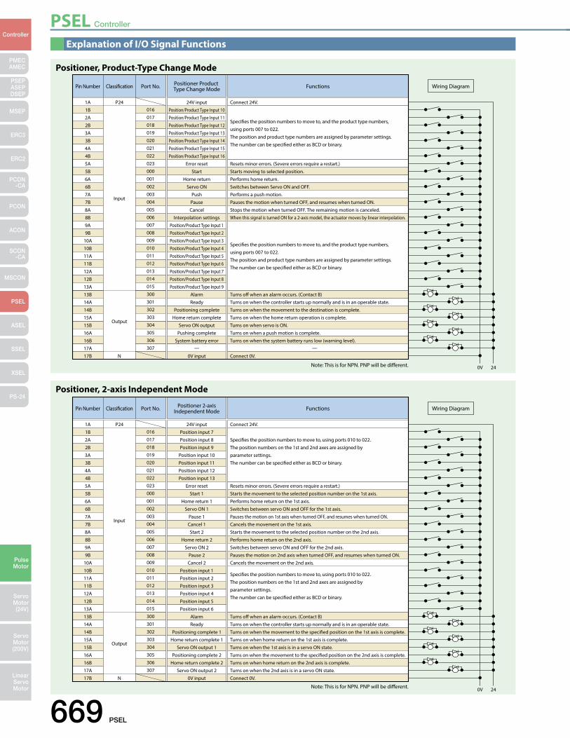
PSEL Controller
669 PSEL
PMECAMEC
Controller
Pulse Motor
Servo Motor (24V)
Servo Motor (200V)
LinearServo Motor
PSEP ASEPDSEP
MSEP
ERC3
ERC2
PCON-CA
PCON
ACON
SCON-CA
MSCON
PSEL
ASEL
SSEL
XSEL
PS-24
Explanation of I/O Signal Functions
Pin Number
24V input Connect 24V.
Positioner Product Type Change Mode Functions
Connect 0V.
0V 24
Wiring Diagram
1A
Resets minor errors. (Severe errors require a restart.)
Turns o when an alarm occurs. (Contact B)Turns on when the controller starts up normally and is in an operable state.Turns on when the movement to the destination is complete.Turns on when the home return operation is complete.Turns on when servo is ON.Turns on when a push motion is complete.Turns on when the system battery runs low (warning level).
Starts moving to selected position.Performs home return.Switches between Servo ON and OFF.Performs a push motion.Pauses the motion when turned OFF, and resumes when turned ON.Stops the motion when turned OFF. The remaining motion is canceled.When this signal is turned ON for a 2-axis model, the actuator moves by linear interpolation.
Species the position numbers to move to, and the product type numbers,using ports 007 to 022. The position and product type numbers are assigned by parameter settings. The number can be specied either as BCD or binary.
Species the position numbers to move to, and the product type numbers,using ports 007 to 022. The position and product type numbers are assigned by parameter settings. The number can be specied either as BCD or binary.
1B2A2B3A3B4A4B5A5B6A6B7A7B8A8B9A9B
10A10B11A11B12A12B13A13B14A14B15A15B16A16B17A17B
Position/Product Type Input 10Position/Product Type Input 11Position/Product Type Input 12Position/Product Type Input 13Position/Product Type Input 14Position/Product Type Input 15Position/Product Type Input 16
Error resetStart
Home returnServo ON
PushPauseCancel
Interpolation settingsPosition/Product Type Input 1Position/Product Type Input 2Position/Product Type Input 3Position/Product Type Input 4Position/Product Type Input 5Position/Product Type Input 6Position/Product Type Input 7Position/Product Type Input 8Position/Product Type Input 9
AlarmReady
Positioning completeHome return complete
Servo ON outputPushing complete
System battery error— —
0V input
Classication
Input
Output
N
P24016
Port No.
017018019020021022023000001002003004005006007008009010011012013014015300301302303304305306307
Positioner, Product-Type Change Mode
Note: This is for NPN. PNP will be different.
Pin Number
24V input Connect 24V.
Positioner 2-axisIndependent Mode Functions
Connect 0V.
0V 24
Wiring Diagram
1A
Resets minor errors. (Severe errors require a restart.)
Turns o when an alarm occurs. (Contact B)Turns on when the controller starts up normally and is in an operable state.Turns on when the movement to the specied position on the 1st axis is complete.Turns on when home return on the 1st axis is complete.Turns on when the 1st axis is in a servo ON state.Turns on when the movement to the specied position on the 2nd axis is complete.Turns on when home return on the 2nd axis is complete.Turns on when the 2nd axis is in a servo ON state.
Starts the movement to the selected position number on the 1st axis.Performs home return on the 1st axis.Switches between servo ON and OFF for the 1st axis.Pauses the motion on 1st axis when turned OFF, and resumes when turned ON.Cancels the movement on the 1st axis.Starts the movement to the selected position number on the 2nd axis.Performs home return on the 2nd axis.Switches between servo ON and OFF for the 2nd axis.Pauses the motion on 2nd axis when turned OFF, and resumes when turned ON.Cancels the movement on the 2nd axis.
Species the position numbers to move to, using ports 010 to 022. The position numbers on the 1st and 2nd axes are assigned by parameter settings. The number can be specied either as BCD or binary.
Species the position numbers to move to, using ports 010 to 022. The position numbers on the 1st and 2nd axes are assigned by parameter settings. The number can be specied either as BCD or binary.
1B2A2B3A3B4A4B5A5B6A6B7A7B8A8B9A9B
10A10B11A11B12A12B13A13B14A14B15A15B16A16B17A17B
Position input 7Position input 8Position input 9
Position input 10Position input 11Position input 12Position input 13
Error resetStart 1
Home return 1Servo ON 1
Pause 1Cancel 1Start 2
Home return 2Servo ON 2
Pause 2Cancel 2
Position input 1Position input 2Position input 3Position input 4Position input 5Position input 6
AlarmReady
Positioning complete 1Home return complete 1
Servo ON output 1Positioning complete 2
Home return complete 2Servo ON output 2
0V input
Classication
Input
Output
N
P24016
Port No.
017018019020021022023000001002003004005006007008009010011012013014015300301302303304305306307
Positioner, 2-axis Independent Mode
Note: This is for NPN. PNP will be different.
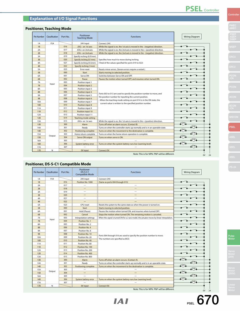
PSEL Controller
PSEL 670
PMECAMEC
Controller
Pulse Motor
Servo Motor (24V)
Servo Motor (200V)
LinearServo Motor
PSEP ASEPDSEP
MSEP
ERC3
ERC2
PCON-CA
PCON
ACON
SCON-CA
MSCON
PSEL
ASEL
SSEL
XSEL
PS-24
Explanation of I/O Signal Functions
Pin Number
24V input Connect 24V.While the signal is on, the 1st axis is moved in the - (negative) direction.While the signal is on, the 2nd axis is moved in the + (positive) direction.While the signal is on, the 2nd axis is moved in the - (negative) direction.
Species how much to move during inching. (Total of the values specied for ports 019 to 022)
PositionerTeaching Mode Functions
Connect 0V.
0V 24
Wiring Diagram
1A
Resets minor errors. (Severe errors require a restart.)
Turns o when an alarm occurs. (Contact B)While the signal is on, the 1st axis is moved in the + (positive) direction.
Turns on when the controller starts up normally and is in an operable state.Turns on when the movement to the destination is complete.Turns on when the home return operation is complete.Turns on when servo is ON.
Turns on when the system battery runs low (warning level).
Starts moving to selected position.Switches between Servo ON and OFF.Pauses the motion when turned OFF, and resumes when turned ON.
Ports 003 to 013 are used to specify the position number to move, and the position number for inputting the current position. - When the teaching mode setting on port 014 is in the ON state, the current value is written to the specied position number.
1B2A2B3A3B4A4B5A5B6A6B7A7B8A8B9A9B
10A10B11A11B12A12B13A13B14A14B15A15B16A16B17A17B
JOG− on 1st axisJOG+ on 2nd axisJOG− on 2nd axis
Specify inching (0.01mm)Specify inching (0.1mm)Specify inching (0.5mm)Specify inching (1mm)
Error resetStart
Servo ONPause
Position input 1Position input 2Position input 3Position input 4Position input 5Position input 6Position input 7Position input 8Position input 9
Position input 10Position input 11
Teaching mode settingJOG+ on 1st axis
AlarmReady
Positioning completeHome return complete
Servo ON output—
—
—
—System battery error
0V input
Classication
Input
Output
N
P24016
Port No.
017018019020021022023000001002003004005006007008009010011012013014015300301302303304305306307
Positioner, Teaching Mode
Note: This is for NPN. PNP will be different.
Pin Number Classication
Input
Output
N
01624V input
———
—
—
—
—
—
—
—
—
—
—
—
———
—
—
—
Connect 24V.(Same as ports 004 through 015)
Port No.Positioner
DS-S-C1Compatible Mode
Functions
Connect 0V.
0V 24
Wiring Diagram
1A P24
Resets the system to the same state as when the power is turned on.
Turns o when an alarm occurs. (Contact A)Turns on when the controller starts up normally and is in an operable state.Turns on when the movement to the destination is complete.
Turns on when the system battery runs low (warning level).
Starts moving to selected position.Pauses the motion when turned ON, and resumes when turned OFF.Stops the motion when turned ON. The remaining motion is canceled.When this signal is turned ON for a 2-axis model, the actuator moves by linear interpolation.
Ports 004 through 016 are used to specify the position number to move. The numbers are specied as BCD.
1B2A2B3A3B4A4B5A5B6A6B7A7B8A8B9A9B
10A10B11A11B12A12B13A13B14A14B15A15B16A16B17A17B
017018019020021022023000001002003004005006007008009010011012013014015300301302303304305306307
Position No. 1000
CPU resetStart
Hold (Pause)Cancel
Interpolation settingsPosition No. 1Position No. 2Position No. 4Position No. 8
Position No. 10Position No. 20Position No. 40Position No. 80
Position No. 100Position No. 200Position No. 400Position No. 800
AlarmReady
Positioning complete
System battery error
0V input
Positioner, DS-S-C1 Compatible Mode
Note: This is for NPN. PNP will be different.
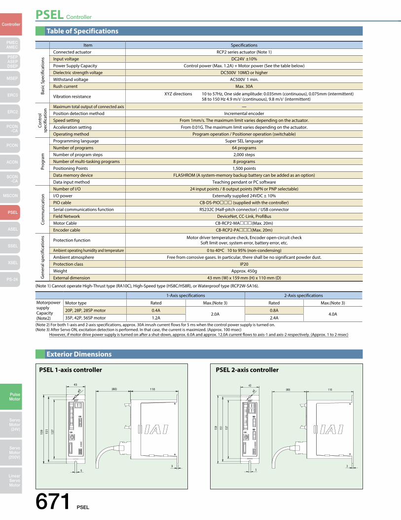
PSEL Controller
671 PSEL
PMECAMEC
Controller
Pulse Motor
Servo Motor (24V)
Servo Motor (200V)
LinearServo Motor
PSEP ASEPDSEP
MSEP
ERC3
ERC2
PCON-CA
PCON
ACON
SCON-CA
MSCON
PSEL
ASEL
SSEL
XSEL
PS-24
Table of Specifications
Exterior Dimensions
(80) 11043
ø5
159
151
137
53
PSEL 1-axis controller
159
151
137
53
43(80) 110
ø5
PSEL 2-axis controller
(Note 1) Cannot operate High-Thrust type (RA10C), High-Speed type (HS8C/HS8R), or Waterproof type (RCP2W-SA16).
Item SpecificationsConnected actuator RCP2 series actuator (Note 1)Input voltage DC24V ±10%Power Supply Capacity Control power (Max. 1.2A) + Motor power (See the table below)Dielectric strength voltage DC500V 10MΩ or higherWithstand voltage AC500V 1 min.Rush current Max. 30A
Vibration resistance XYZ directions 10 to 57Hz, One side amplitude: 0.035mm (continuous), 0.075mm (intermittent) 58 to 150 Hz 4.9 m/s2 (continuous), 9.8 m/s2 (intermittent)
Maximum total output of connected axis —Position detection method Incremental encoderSpeed setting From 1mm/s. The maximum limit varies depending on the actuator.Acceleration setting From 0.01G. The maximum limit varies depending on the actuator.Operating method Program operation / Positioner operation (switchable)Programming language Super SEL languageNumber of programs 64 programsNumber of program steps 2,000 stepsNumber of multi-tasking programs 8 programsPositioning Points 1,500 pointsData memory device FLASHROM (A system-memory backup battery can be added as an option)Data input method Teaching pendant or PC softwareNumber of I/O 24 input points / 8 output points (NPN or PNP selectable)I/O power Externally supplied 24VDC ± 10%PIO cable CB-DS-PIO (supplied with the controller)Serial communications function RS232C (Half-pitch connector) / USB connectorField Network DeviceNet, CC-Link, ProfiBusMotor Cable CB-RCP2-MA(Max. 20m)Encoder cable CB-RCP2-PA(Max. 20m)
Protection function Motor driver temperature check, Encoder open-circuit checkSoft limit over, system error, battery error, etc.
Ambient operating humidity and temperature 0 to 40ºC 10 to 95% (non-condensing)Ambient atmosphere Free from corrosive gases. In particular, there shall be no significant powder dust.Protection class IP20Weight Approx. 450gExternal dimension 43 mm (W) x 159 mm (H) x 110 mm (D)
Basi
c Sp
ecifi
catio
nsCo
ntro
l sp
ecifi
catio
nPr
ogra
mCo
mm
unic
atio
nG
ener
al s
peci
ficat
ions
(Note 2) For both 1-axis and 2-axis specifications, approx. 30A inrush current flows for 5 ms when the control power supply is turned on.(Note 3) After Servo ON, excitation detection is performed. In that case, the current is maximized. (Approx. 100 msec) However, if motor drive power supply is turned on after a shut-down, approx. 6.0A and approx. 12.0A current flows to axis-1 and axis-2 respectively. (Approx. 1 to 2 msec)
1-Axis specifications 2-Axis specifications
Motorpower supply Capacity (Note2)
Motor type Rated Max.(Note 3) Rated Max.(Note 3)
20P, 28P, 28SP motor 0.4A2.0A
0.8A4.0A
35P, 42P, 56SP motor 1.2A 2.4A
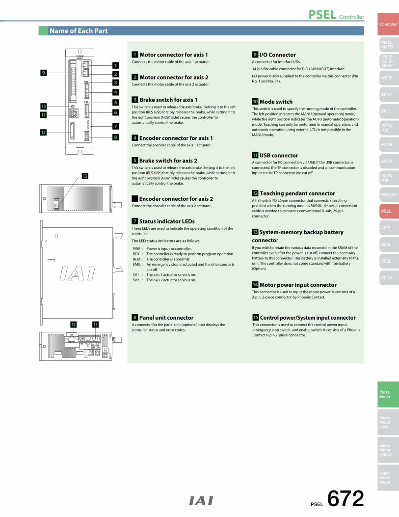
PSEL Controller
PSEL 672
PMECAMEC
Controller
Pulse Motor
Servo Motor (24V)
Servo Motor (200V)
LinearServo Motor
PSEP ASEPDSEP
MSEP
ERC3
ERC2
PCON-CA
PCON
ACON
SCON-CA
MSCON
PSEL
ASEL
SSEL
XSEL
PS-24
Name of Each Part
13
14
19
1 Motor connector for axis 1 Connects the motor cable of the axis 1 actuator.
8 Panel unit connector A connector for the panel unit (optional) that displays the controller status and error codes.
9 I/O Connector A connector for interface I/Os.
34-pin flat cable connector for DIO (24IN/8OUT) interface.
I/O power is also supplied to the controller via this connector (Pin No. 1 and No. 34).
10 Mode switch This switch is used to specify the running mode of the controller. The left position indicates the MANU (manual operation) mode, while the right position indicates the AUTO (automatic operation) mode. Teaching can only be performed in manual operation, and automatic operation using external I/Os is not possible in the MANU mode.
11 USB connectorA connector for PC connection via USB. If the USB connector is connected, the TP connector is disabled and all communication inputs to the TP connector are cut off.
12 Teaching pendant connectorA half-pitch I/O 26-pin connector that connects a teaching pendant when the running mode is MANU. A special conversion cable is needed to connect a conventional D-sub, 25-pin connector.
14 Motor power input connectorThis connector is used to input the motor power. It consists of a 2-pin, 2-piece connector by Phoenix Contact.
15 Control power/System input connectorThis connector is used to connect the control power input, emergency stop switch, and enable switch. It consists of a Phoenix Contact 6-pin 2-piece connector.
13 System-memory backup battery connectorIf you wish to retain the various data recorded in the SRAM of the controller even after the power is cut off, connect the necessary battery to this connector. This battery is installed externally to the unit. The controller does not come standard with the battery (Option).
2 Motor connector for axis 2 Connects the motor cable of the axis 2 actuator.
4 Encoder connector for axis 1Connect the encoder cable of the axis 1 actuator.
6 Encoder connector for axis 2Connect the encoder cable of the axis 2 actuator.
7 Status indicator LEDsThese LEDs are used to indicate the operating condition of the controller.
The LED status indicators are as follows:
3 Brake switch for axis 1 This switch is used to release the axis brake. Setting it to the left position (RLS side) forcibly releases the brake, while setting it to the right position (NOM side) causes the controller to automatically control the brake.
5 Brake switch for axis 2 This switch is used to release the axis brake. Setting it to the left position (RLS side) forcibly releases the brake, while setting it to the right position (NOM side) causes the controller to automatically control the brake.
PWR : Power is input to controller.RDY : The controller is ready to perform program operation. ALM : The controller is abnormal. EMG : An emergency stop is actuated and the drive source is cut off. SV1 : The axis 1 actuator servo is on. SV2 : The axis 2 actuator servo is on.
10
11
12
2
3
4
5
6
8
7
15
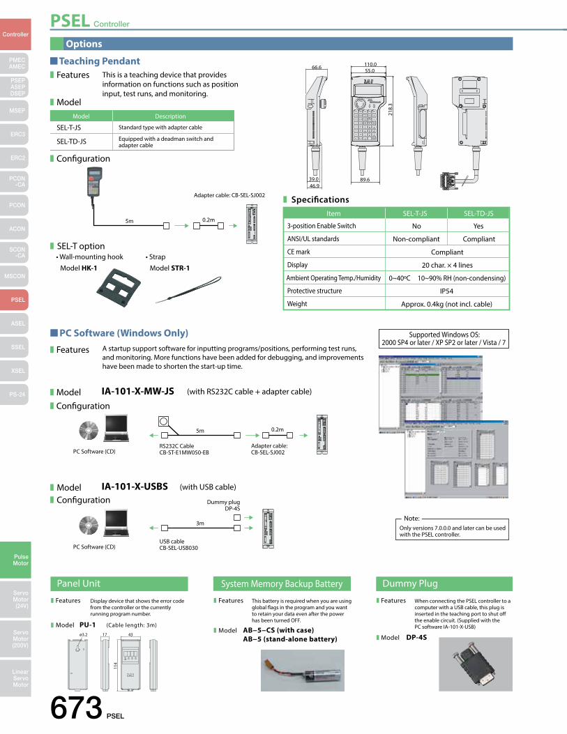
PSEL Controller
673 PSEL
PMECAMEC
Controller
Pulse Motor
Servo Motor (24V)
Servo Motor (200V)
LinearServo Motor
PSEP ASEPDSEP
MSEP
ERC3
ERC2
PCON-CA
PCON
ACON
SCON-CA
MSCON
PSEL
ASEL
SSEL
XSEL
PS-24
This is a teaching device that provides information on functions such as position input, test runs, and monitoring.
Features
Model
Conguration
SEL-T option
A startup support software for inputting programs/positions, performing test runs, and monitoring. More functions have been added for debugging, and improvements have been made to shorten the start-up time.
Features
ModelConguration
IA-101-X-MW-JS (with RS232C cable + adapter cable)
Specications
SEL-T-JS
SEL-TD-JS
Standard type with adapter cable
Equipped with a deadman switch and adapter cable
Model Description
5m
5m
Adapter cable: CB-SEL-SJ002
0.2m
0.2m
Adapter cable: CB-SEL-SJ002PC Software (CD)
RS232C CableCB-ST-E1MW050-EB
IA-101-X-USBS (with USB cable)
3m
Dummy plugDP-4S
PC Software (CD)USB cableCB-SEL-USB030
Only versions 7.0.0.0 and later can be used with the PSEL controller.
Note:
ModelConguration
66.6
46.939.0
55.0
89.6
218.
3
110.0Teaching Pendant
PC Software (Windows Only)
• Wall-mounting hook
Model HK-1• Strap
Model STR-1
Supported Windows OS:2000 SP4 or later / XP SP2 or later / Vista / 7
3-position Enable Switch No Yes
Compliant
Item SEL-T-JS SEL-TD-JS
ANSI/UL standards
CE mark
Display
Ambient Operating Temp./Humidity
Protective structure
Weight
Non-compliant
20 char. × 4 lines
0~40ºC 10~90% RH (non-condensing)
IP54
Approx. 0.4kg (not incl. cable)
Compliant
Options
Panel Unit System Memory Backup Battery
Features Display device that shows the error code from the controller or the currently running program number.
Model PU-1 (Cable length: 3m)
This battery is required when you are using global ags in the program and you want to retain your data even after the power has been turned OFF.
Features
Model AB−5−CS (with case)AB−5 (stand-alone battery)
Dummy Plug
When connecting the PSEL controller to a computer with a USB cable, this plug is inserted in the teaching port to shut o the enable circuit. (Supplied with the PC software IA-101-X-USB)
Features
Model DP-4Sø3.2 17
114
43
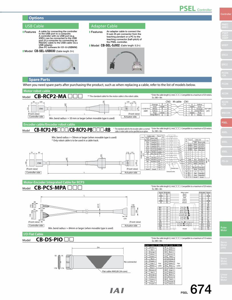
PSEL Controller
PSEL 674
PMECAMEC
Controller
Pulse Motor
Servo Motor (24V)
Servo Motor (200V)
LinearServo Motor
PSEP ASEPDSEP
MSEP
ERC3
ERC2
PCON-CA
PCON
ACON
SCON-CA
MSCON
PSEL
ASEL
SSEL
XSEL
PS-24
Options
Spare Parts
A cable for connecting the controller to the USB port to a computer. A controller with no USB port (e.g. XSEL) can be connected to the USB port of a computer by connecting an RS232C cable to the USB cable via a USB adapter. (See PC software IA-101-X-USBMW)
USB Cable Adapter CableFeatures
Model CB-SEL-USB030 (Cable length: 3m)
An adapter cable to connect the D-sub 25-pin connector from the teaching pendant or a PC to the teaching connector (half-pitch) of the PSEL controller.
Features
Model CB-SEL-SJ002 (Cable length: 0.2m)
When you need spare parts after purchasing the product, such as when replacing a cable, refer to the list of models below.
Model CB-DS-PIO * Enter the cable length (L) into. Compatible to a maximum of 10 meters. Ex.: 080 = 8m
ColorPin No. Wire
Flatcable
crimped
Wire
Flatcable
crimped
ColorPin No.1A Brown 1 9B Gray 2
1B 1A
17B 17A
Flat cable AWG28 (34-core)
2m
No connector
1B2A2B3A3B4A4B5A5B6A6B7A7B8A8B9A
Red 1Orange 1Yellow 1Green 1
Blue1Purple 1Gray 1
White 1Black 1
Brown-2Red 2
Orange 2Yellow 2Green 2Blue 2
Purple 2
10A10B11A11B12A12B13A13B14A14B15A15B16A16B17A17B
White 2Black 2
Brown-3Red 3
Orange 3Yellow 3Green 3Blue 3
Purple 3Gray 3
White 3Black 3
Brown-4Red 4
Orange 4Yellow 4
I/O Flat Cable
* Enter the cable length (L) into. Compatible to a maximum of 20 meters. Ex.: 080 = 8m
PHD
R-16
VS(J
ST)
XMP-
18V
(JST)
Blue (Red 1)
C N4
C N 2Cable color
Signal PinNo.
Brown Light Gray (Black 1)
Orange (Black 2)
1
L S + L S − B K + B K − E N A E N A E N B E N B
V P S V B B
(N.C)(N.C)(N.C)F.G
E N A E N A E N B E N B
GNDGND
V B B V P S
L S + L S −
B K + B K − F . G
16
Shield wire
Ground wire
Cable color Standard
Cable Robot Cable
Standard Cable Robot Cable
SignalPinNo.
L
CN2
CN4
(5) (8) (13) (15)
(18)
(ø9)
(35)
(25)
WhiteRedGray
BrownGreenPurple
Pink
YellowOrange
Blue
Ground
Orange (Red 2)Orange (Black 1)Orange (Red 1)
Light Gray (Black 1)Light Gray (Red 1)
White (Black 1)White (Red 1)
Yellow (Black 1)Pink (Red 1)
Pink (Black 1)
Ground
151413121110987654321
23456789
101112131415161718
GreenPurple
Pink
BlueOrangeYellow
Blue (Red 1)White
RedGray
Ground
Light Gray (Red 1)White (Black 1)White (Red 1)
Pink (Black 1)Pink (Red 1)Yellow (Black 1)
Orange (Black 2)Orange (Red 2)
Orange (Black 1)Orange (Red 1)
Ground
(Front view) (Front view)
Actuator sideController side
Model CB-RCP2-PB/CB-RCP2-PB-RBEncoder cable/Encoder robot cable
* The standard cable for the encoder cable is a normal cable. A robot cable can be specified as an option.
Min. bend radius r = 50mm or larger (when movable type is used)* Only robot cable is to be used in a cable track.
* Enter the cable length (L) into. Compatible to a maximum of 20 meters. Ex.: 080 = 8m
L
(15)
(ø12
)
A
Shield
Pink (Red )Pink (Blue )
White (Red )White (Blue )Orange (Red )Orange (Blue )
Gray (Red )Gray (Blue )
Orange (Blue Contiguous)Gray (Red Contiguous)Gray (Blue Contiguous)
BlackWhite
RedGreenYellowBrown
B1 A1 A
BK+ 14
(18)
(8)
(20)
(8)
(5)
(30)
(18)
(23)
Signal Pin Number (Wire color) Pin Number Signal
VMM/AB
VMM/B
A2A1B3B2A3
BK−LS+LS−A+A−B+B−NCVPSVCCGNDNCFG
1316151211109876541
B1A2B2A3B3A4B4A5B5A6B6A7B7A8B8A9B9
A10B10A11B11
VMM/AB
VMM/BNCNC
BK+BK−LS+LS−A+A−B+B−NCVPSVCCGNDNCFG
(Front view) (Front view)
Actuator sideController side
Model CB-PCS-MPA Motor-Encoder Integrated Cable for RCP3
Min. bend radius r = 84mm or larger (when movable type is used)
A A
I-1318119-3(AMP)
SLP-06V(JST)
Orange Yellow123456
(20)(8)
(Front view)
(15)
L
CN3CN1
(ø8)
(28) (14)
(14)
(20)
(Front view)Actuator sideController side
GrayWhiteYellow
PinkOrange (Black 1)
VMMBA
VMMB
A1A2A3B1B2B3
VMMAB
VMMB
GrayOrange
Orange (Black 1)Pink
White
Model CB-RCP2-MA Motor robot cable
* * The standard cable for the motor cable is the robot cable.
Min. bend radius r = 50 mm or larger (when movable type is used)
* Enter the cable length (L) into. Compatible to a maximum of 20 meters. Ex.: 080 = 8m
CN3 M cable CN1
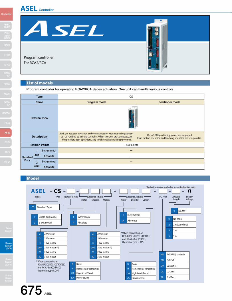
ASEL Controller
675 ASEL
PMECAMEC
Controller
Pulse Motor
Servo Motor (24V)
Servo Motor (200V)
LinearServo Motor
PSEP ASEPDSEP
MSEP
ERC3
ERC2
PCON-CA
PCON
ACON
SCON-CA
MSCON
PSEL
ASEL
SSEL
XSEL
PS-24
List of modelsProgram controller for operating RCA2/RCA Series actuators. One unit can handle various controls.
Model
0CSASELSeries Type Number of Axes
Motor Encoder Option Motor Encoder OptionI/O Cable
LengthPower/Voltage
* 2nd axis specs not applicable to the single-axis model.
I/O Type
CS Standard Type
20
20S
20W motor
20W motor (*)
10 10W motor
5 5W motor
2 2W motor
30 30W motor
1 Single-axis model
2 2-axis model
I Incremental
A Absolute
I Incremental
A Absolute
DV DeviceNet
CC CC-Link
PR ProBus
NP PIO NPN (standard)
PN PIO PNP
B Brake
H Home sensor compatible
HA High Accel./Decel.
LA Power-saving
B Brake
H Home sensor compatible
HA High Accel./Decel.
LA Power-saving
0 DC24V
0 No cable
2 2m (standard)
3 3m
5 5m
20
20S
20W motor
20W motor (*)
30 30W motor
10 10W motor
5 5W motor
2 2W motor
(Specs for 1st axis) (Specs for 2nd axis)
* When connecting an RCA-RA3/RGS3/RGD3 and RCA2-SA4/TA5, the motor type is 20S.
* When connecting an RCA-RA3/RGS3/RGD3 and RCA2-SA4/TA5, the motor type is 20S.
Program controllerFor RCA2/RCA
Type CS
Name Program mode Positioner mode
External view
DescriptionBoth the actuator operation and communication with external equipment can be handled by a single controller. When two axes are connected, arc interpolation, path operations, and synchronization can be performed.
Up to 1,500 positioning points are supported. Push-motion operation and teaching operation are also possible.
Position Points 1,500 points
Standard Price
1 axis
Incremental —
Absolute —
2 axes
Incremental —
Absolute —
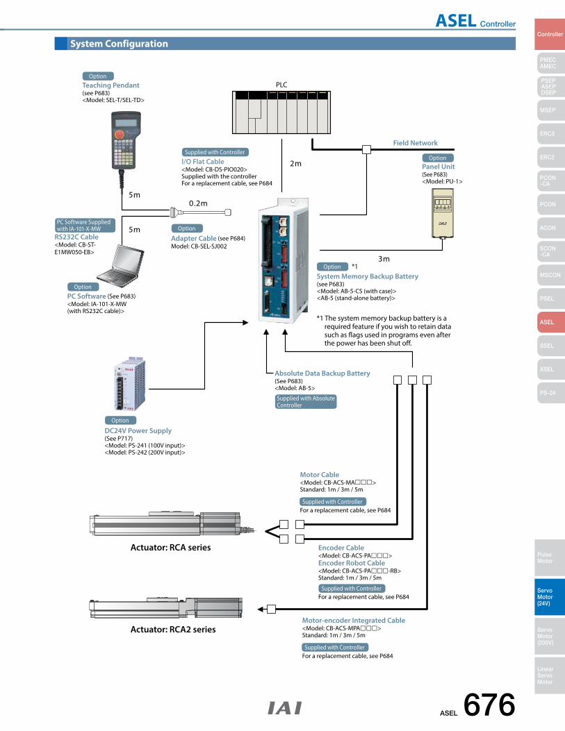
ASEL Controller
ASEL 676
PMECAMEC
Controller
Pulse Motor
Servo Motor (24V)
Servo Motor (200V)
LinearServo Motor
PSEP ASEPDSEP
MSEP
ERC3
ERC2
PCON-CA
PCON
ACON
SCON-CA
MSCON
PSEL
ASEL
SSEL
XSEL
PS-24
System Configuration
2m
0.2m
3m
5m
5m
PLCOption
Teaching Pendant (see P683)<Model: SEL-T/SEL-TD>
Supplied with Controller
I/O Flat Cable<Model: CB-DS-PIO020>Supplied with the controllerFor a replacement cable, see P684
Option
Adapter Cable (see P684)Model: CB-SEL-SJ002
Field Network
OptionPanel Unit(See P683)<Model: PU-1>
OptionPC Software (See P683)<Model: IA-101-X-MW (with RS232C cable)>
Actuator: RCA series
Actuator: RCA2 series
PC Software Suppliedwith IA-101-X-MW
RS232C Cable <Model: CB-ST- E1MW050-EB>
*1 The system memory backup battery is a required feature if you wish to retain data such as flags used in programs even after the power has been shut off.
System Memory Backup Battery (see P683)<Model: AB-5-CS (with case)><AB-5 (stand-alone battery)>
*1Option
DC24V Power Supply(See P717) <Model: PS-241 (100V input)><Model: PS-242 (200V input)>
Option
Motor Cable<Model: CB-ACS-MA>Standard: 1m / 3m / 5m
For a replacement cable, see P684Supplied with Controller
Encoder Cable<Model: CB-ACS-PA>Encoder Robot Cable<Model: CB-ACS-PA-RB>Standard: 1m / 3m / 5m
For a replacement cable, see P684Supplied with Controller
Motor-encoder Integrated Cable<Model: CB-ACS-MPA>Standard: 1m / 3m / 5m
For a replacement cable, see P684Supplied with Controller
Supplied with Absolute Controller
Absolute Data Backup Battery(See P683)<Model: AB-5>
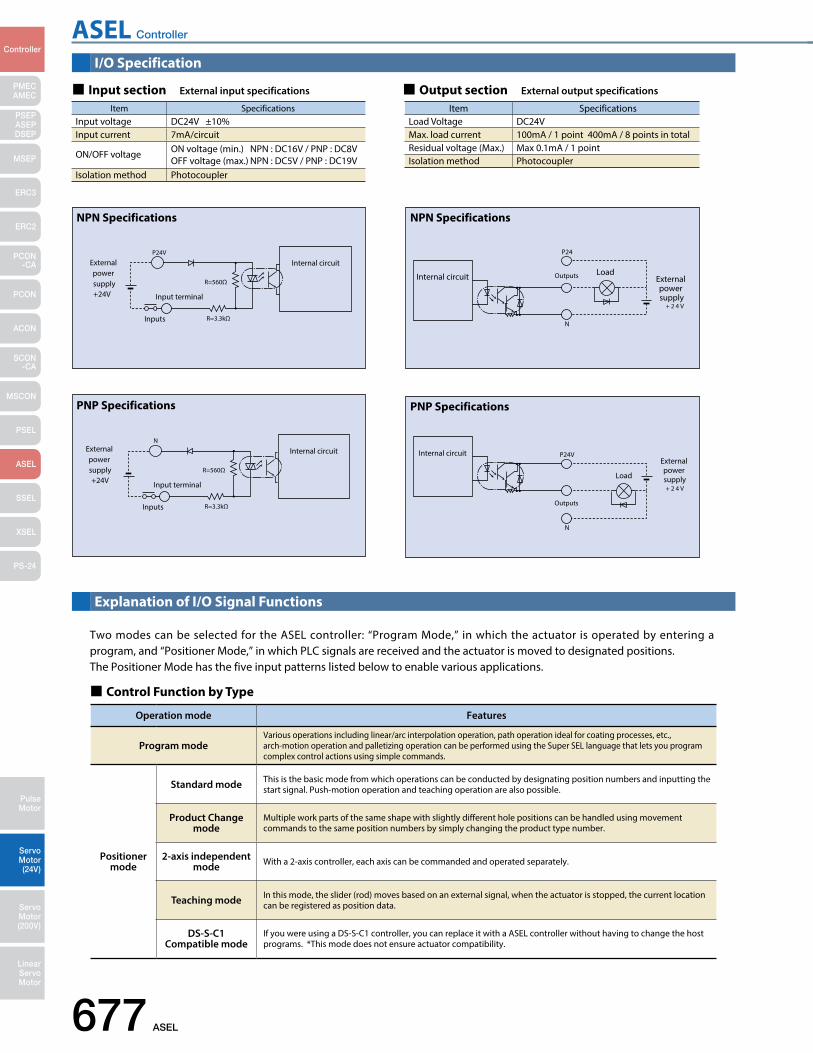
ASEL Controller
677 ASEL
PMECAMEC
Controller
Pulse Motor
Servo Motor (24V)
Servo Motor (200V)
LinearServo Motor
PSEP ASEPDSEP
MSEP
ERC3
ERC2
PCON-CA
PCON
ACON
SCON-CA
MSCON
PSEL
ASEL
SSEL
XSEL
PS-24
I/O Specification
Explanation of I/O Signal Functions
Input section External input specifications Output section External output specifications
Item SpecificationsInput voltage DC24V ±10%Input current 7mA/circuit
ON/OFF voltage ON voltage (min.) NPN : DC16V / PNP : DC8VOFF voltage (max.) NPN : DC5V / PNP : DC19V
Isolation method Photocoupler
Item SpecificationsLoad Voltage DC24VMax. load current 100mA / 1 point 400mA / 8 points in totalResidual voltage (Max.) Max 0.1mA / 1 pointIsolation method Photocoupler
Control Function by Type
Operation mode Features
Program modeVarious operations including linear/arc interpolation operation, path operation ideal for coating processes, etc., arch-motion operation and palletizing operation can be performed using the Super SEL language that lets you program complex control actions using simple commands.
Positioner mode
Standard mode This is the basic mode from which operations can be conducted by designating position numbers and inputting the start signal. Push-motion operation and teaching operation are also possible.
Product Change mode
Multiple work parts of the same shape with slightly different hole positions can be handled using movement commands to the same position numbers by simply changing the product type number.
2-axis independent mode With a 2-axis controller, each axis can be commanded and operated separately.
Teaching mode In this mode, the slider (rod) moves based on an external signal, when the actuator is stopped, the current location can be registered as position data.
DS-S-C1Compatible mode
If you were using a DS-S-C1 controller, you can replace it with a ASEL controller without having to change the host programs. *This mode does not ensure actuator compatibility.
Two modes can be selected for the ASEL controller: “Program Mode,” in which the actuator is operated by entering a program, and “Positioner Mode,” in which PLC signals are received and the actuator is moved to designated positions. The Positioner Mode has the five input patterns listed below to enable various applications.
P24V
R=3.3kΩInputs
R=560Ω
+24V
External power supply
Input terminal
Internal circuit
NPN Specifications
P24
N
OutputsInternal circuit Load
+ 2 4 V
External power supply
NPN Specifications
N
R=3.3kΩInputs
R=560Ω
+24V
External power supply
Input terminal
Internal circuit
PNP Specifications
P24V
N
Outputs
Internal circuit
+ 2 4 V
External power supply Load
PNP Specifications
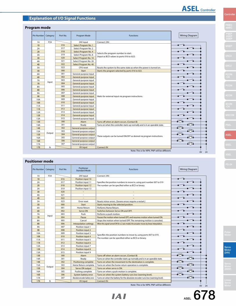
ASEL Controller
ASEL 678
PMECAMEC
Controller
Pulse Motor
Servo Motor (24V)
Servo Motor (200V)
LinearServo Motor
PSEP ASEPDSEP
MSEP
ERC3
ERC2
PCON-CA
PCON
ACON
SCON-CA
MSCON
PSEL
ASEL
SSEL
XSEL
PS-24
Explanation of I/O Signal Functions
Pin Number Category
Input
Output
N
01624V input Connect 24V.
Port No. Program Mode Functions
Resets the system to the same state as when the power is turned on.
Turns o when an alarm occurs. (Contact B)Turns on when the controller starts up normally and is in an operable state.
Connect 0V.
These outputs can be turned ON/OFF as desired via program instructions.
Starts the program selected by ports 016 to 022.
Waits for external input via program instructions.
Selects the program number to start. (Input as BCD values to ports 016 to 022)
0V 24
Wiring Diagram
1A P241B2A2B3A3B4A4B5A5B6A6B7A7B8A8B9A9B
10A10B11A11B12A12B13A13B14A14B15A15B16A16B17A17B
017018019020021022023000001002003004005006007008009010011012013014015300301302303304305306307
Select Program No. 1Select Program No. 2Select Program No. 4Select Program No. 8
Select Program No. 10Select Program No. 20Select Program No. 40
CPU resetStart
General-purpose inputGeneral-purpose inputGeneral-purpose inputGeneral-purpose inputGeneral-purpose inputGeneral-purpose inputGeneral-purpose inputGeneral-purpose inputGeneral-purpose inputGeneral-purpose inputGeneral-purpose inputGeneral-purpose inputGeneral-purpose inputGeneral-purpose inputGeneral-purpose input
AlarmReady
General-purpose outputGeneral-purpose outputGeneral-purpose outputGeneral-purpose outputGeneral-purpose outputGeneral-purpose output
0V input
Program mode
Note: This is for NPN. PNP will be different.
Pin Number Category
Input
Output
N
01624V input Connect 24V.
Port No. PositionerStandard Mode Functions
Resets minor errors. (Severe errors require a restart.)
−−−
Turns o when an alarm occurs. (Contact B)Turns on when the controller starts up normally and is in an operable state.Turns on when the movement to the destination is complete.Turns on when the home return operation is complete.Turns on when servo is ON.Turns on when a push motion is complete.Turns on when the system battery runs low (warning level).Turns on when the battery for the absolute encoder runs low (warning level).Connect 0V.
Starts moving to the selected position.Performs Home Return.Switches between Servo ON and OFF.Performs a push motion.Pauses the motion when turned OFF, and resumes motion when turned ON.Stops the motion when turned OFF. The remaining motion is canceled.When this signal turned ON for a 2-axis model, the actuator moves by linear interpolation.
Species the position numbers to move to, using ports 007 to 019. The number can be specied either as BCD or binary.
Species the position numbers to move to, using port number 007 to 019 The number can be specied either as BCD or binary.
0V 24
Wiring Diagram
1A P241B2A2B3A3B4A4B5A5B6A6B7A7B8A8B9A9B
10A10B11A11B12A12B13A13B14A14B15A15B16A16B17A17B
017018019020021022023000001002003004005006007008009010011012013014015300301302303304305306307
Position input 10Position input 11Position input 12Position input 13
Error resetStart
Home ReturnServo ON
PushPauseCancel
Interpolation settingsPosition input 1Position input 2Position input 3Position input 4Position input 5Position input 6Position input 7Position input 8Position input 9
AlarmReady
Positioning completeHome Return complete
Servo ON outputPushing complete
System battery errorAbsolute encoder battery error
0V input
Positioner mode
Note: This is for NPN. PNP will be different.
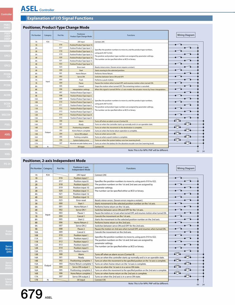
ASEL Controller
679 ASEL
PMECAMEC
Controller
Pulse Motor
Servo Motor (24V)
Servo Motor (200V)
LinearServo Motor
PSEP ASEPDSEP
MSEP
ERC3
ERC2
PCON-CA
PCON
ACON
SCON-CA
MSCON
PSEL
ASEL
SSEL
XSEL
PS-24
Explanation of I/O Signal Functions
Pin Number Category
Input
Output
N
016
24V input Connect 24V.
Port No.Positioner
Product Type Change ModeFunctions
Connect 0V.
0V 24
Wiring Diagram
1A P24
Resets minor errors. (Severe errors require a restart.)
Turns o when an alarm occurs (Contact B)
Turns on when the controller starts up normally and is in an operable state.
Turns on when the movement to the destination is complete.
Turns on when the home return operation is complete.
Turns on when servo is ON.
Turns on when a push motion is complete.
Turns on when the system battery runs low (warning level).
Turns on when the battery for the absolute encoder runs low (warning level).
Starts moving to the selected position.
Performs Home Return.
Switches between Servo ON and OFF.
Performs a push motion.
Pauses the motion when turned OFF, and resumes motion when turned ON.
Stops the motion when turned OFF. The remaining motion is canceled.
When this signal is turned ON for a 2-axis model, the actuator moves by linear interpolation.
Species the position numbers to move to, and the product type numbers,
using ports 007 to 022.
The position and product type numbers are assigned by parameter settings.
The number can be specied either as BCD or binary.
Species the position numbers to move to, and the product type numbers,
using ports 007 to 022.
The position and product type numbers are assigned by parameter settings.
The number can be specied either as BCD or binary.
1B
2A
2B
3A
3B
4A
4B
5A
5B
6A
6B
7A
7B
8A
8B
9A
9B
10A
10B
11A
11B
12A
12B
13A
13B
14A
14B
15A
15B
16A
16B
17A
17B
017
018
019
020
021
022
023
000
001
002
003
004
005
006
007
008
009
010
011
012
013
014
015
300
301
302
303
304
305
306
307
Position/Product Type Input 10
Position/Product Type Input 11
Position/Product Type Input 12
Position/Product Type Input 13
Position/Product Type Input 14
Position/Product Type Input 15
Position/Product Type Input 16
Error reset
Start
Home Return
Servo ON
Push
Pause
Cancel
Interpolation settings
Position/Product Type Input 1
Position/Product Type Input 2
Position/Product Type Input 3
Position/Product Type Input 4
Position/Product Type Input 5
Position/Product Type Input 6
Position/Product Type Input 7
Position/Product Type Input 8
Position/Product Type Input 9
Alarm
Ready
Positioning complete
Home Return complete
Servo ON output
Pushing complete
System battery error
Absolute encoder battery error
0V input
Positioner, Product-Type Change Mode
Note: This is for NPN. PNP will be different.
Pin Number Category
Input
Output
N
01624V input Connect 24V.
Port No. Positioner 2-axis Independent Mode Functions
Connect 0V.
0V 24
Wiring Diagram
1A P24
Resets minor errors. (Severe errors require a restart.)
Turns o when an alarm occurs (Contact B)Turns on when the controller starts up normally and is in an operable state.Turns on when the movement to the specied position on the 1st axis is complete.Turns on when home return on the 1st axis is complete.Turns on when the 1st axis is in a servo ON state.Turns on when the movement to the specied position on the 2nd axis is complete.Turns on when home return on the 2nd axis is complete.Turns on when the 2nd axis is in a servo ON state.
Starts movement to the selected position number on the 1st axis.Performs home return on the 1st axis.Switches between servo ON and OFF for the 1st axis.
Cancels the movement on the 1st axis.Starts the movement to the selected position number on the 2nd axis.Performs home return on the 2nd axis.Switches between servo ON and OFF for the 2nd axis.
Cancels the movement on the 2nd axis.
Species the position numbers to move to, using ports 010 to 022. The position numbers on the 1st and 2nd axes are assigned by parameter settings. The number can be specied either as BCD or binary.
Species the position numbers to move to, using ports 010 to 022. The position numbers on the 1st and 2nd axes are assigned by parameter settings. The number can be specied either as BCD or binary.
Pauses the motion on 1st axis when turned OFF, and resumes motion when turned ON.
Pauses the motion on 2nd axis when turned OFF, and resumes when turned ON.
1B2A2B3A3B4A4B5A5B6A6B7A7B8A8B9A9B
10A10B11A11B12A12B13A13B14A14B15A15B16A16B17A17B
017018019020021022023000001002003004005006007008009010011012013014015300301302303304305306307
Position input 7Position input 8Position input 9
Position input 10Position input 11Position input 12Position input 13
Error resetStart 1
Home Return 1Servo ON 1
Pause 1Cancel 1Start 2
Home Return 2Servo ON 2
Pause 2Cancel 2
Position input 1Position input 2Position input 3Position input 4Position input 5Position input 6
AlarmReady
Positioning complete 1Home Return complete 1
Servo ON output 1Positioning complete 2Home Return complete 2
Servo ON output 20V input
Positioner, 2-axis Independent Mode
Note: This is for NPN. PNP will be different.
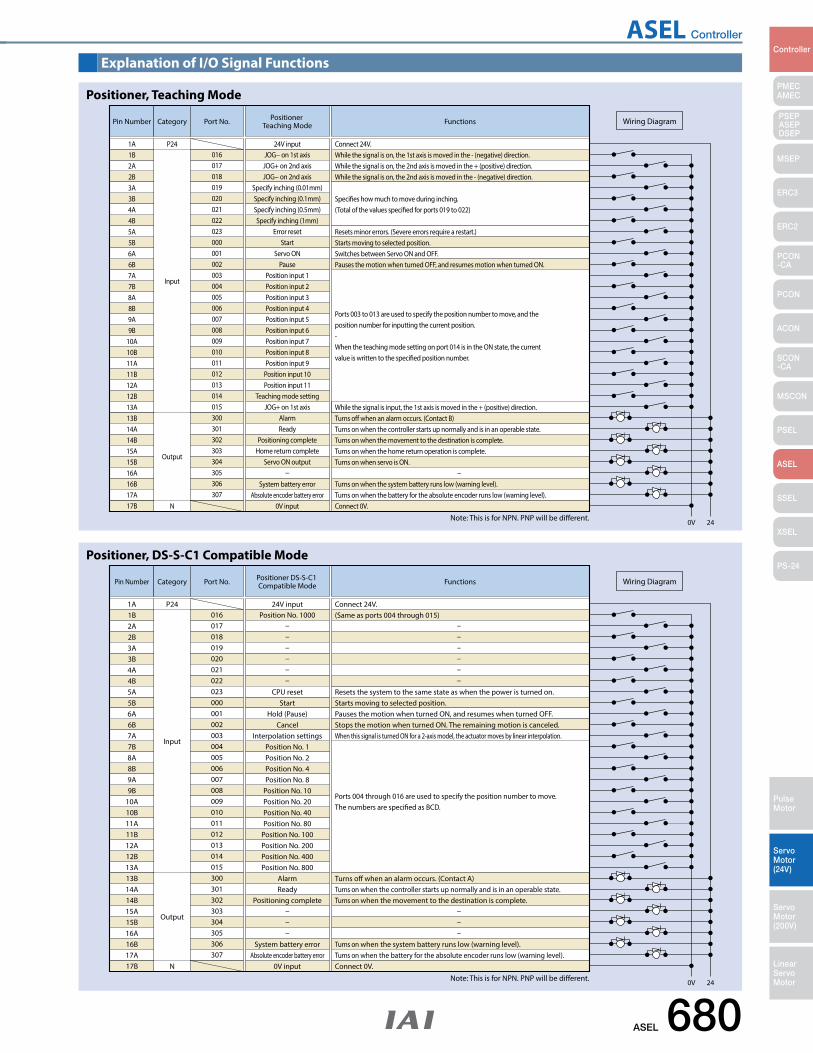
ASEL Controller
ASEL 680
PMECAMEC
Controller
Pulse Motor
Servo Motor (24V)
Servo Motor (200V)
LinearServo Motor
PSEP ASEPDSEP
MSEP
ERC3
ERC2
PCON-CA
PCON
ACON
SCON-CA
MSCON
PSEL
ASEL
SSEL
XSEL
PS-24
Explanation of I/O Signal Functions
Pin Number Category
Input
Output
N
01624V input Connect 24V.
While the signal is on, the 1st axis is moved in the - (negative) direction.While the signal is on, the 2nd axis is moved in the + (positive) direction.While the signal is on, the 2nd axis is moved in the - (negative) direction.
Species how much to move during inching. (Total of the values specied for ports 019 to 022)
Port No. Positioner Teaching Mode Functions
Connect 0V.
0V 24
Wiring Diagram
1A P24
Resets minor errors. (Severe errors require a restart.)
Turns o when an alarm occurs. (Contact B)While the signal is input, the 1st axis is moved in the + (positive) direction.
Turns on when the controller starts up normally and is in an operable state.Turns on when the movement to the destination is complete.Turns on when the home return operation is complete.Turns on when servo is ON.
−Turns on when the system battery runs low (warning level).Turns on when the battery for the absolute encoder runs low (warning level).
Starts moving to selected position.Switches between Servo ON and OFF.Pauses the motion when turned OFF, and resumes motion when turned ON.
Ports 003 to 013 are used to specify the position number to move, and the position number for inputting the current position. - When the teaching mode setting on port 014 is in the ON state, the current value is written to the specied position number.
1B2A2B3A3B4A4B5A5B6A6B7A7B8A8B9A9B
10A10B11A11B12A12B13A13B14A14B15A15B16A16B17A17B
017018019020021022023000001002003004005006007008009010011012013014015300301302303304305306307
JOG− on 1st axisJOG+ on 2nd axisJOG− on 2nd axis
Specify inching (0.01mm)Specify inching (0.1mm)Specify inching (0.5mm)Specify inching (1mm)
Error resetStart
Servo ONPause
Position input 1Position input 2Position input 3Position input 4Position input 5Position input 6Position input 7Position input 8Position input 9
Position input 10Position input 11
Teaching mode settingJOG+ on 1st axis
AlarmReady
Positioning completeHome return complete
Servo ON output
System battery errorAbsolute encoder battery error
0V input
Positioner, Teaching Mode
Note: This is for NPN. PNP will be different.
Pin Number Category
Input
Output
N
01624V input Connect 24V.
(Same as ports 004 through 015)
Port No. Positioner DS-S-C1 Compatible Mode Functions
Connect 0V.
0V 24
Wiring Diagram
1A P24
Resets the system to the same state as when the power is turned on.
Turns o when an alarm occurs. (Contact A)Turns on when the controller starts up normally and is in an operable state.Turns on when the movement to the destination is complete.
Turns on when the system battery runs low (warning level).Turns on when the battery for the absolute encoder runs low (warning level).
Starts moving to selected position.Pauses the motion when turned ON, and resumes when turned OFF.Stops the motion when turned ON. The remaining motion is canceled.When this signal is turned ON for a 2-axis model, the actuator moves by linear interpolation.
Ports 004 through 016 are used to specify the position number to move. The numbers are specied as BCD.
1B2A2B3A3B4A4B5A5B6A6B7A7B8A8B9A9B
10A10B11A11B12A12B13A13B14A14B15A15B16A16B17A17B
017018019020021022023000001002003004005006007008009010011012013014015300301302303304305306307
Position No. 1000
CPU resetStart
Hold (Pause)Cancel
Interpolation settingsPosition No. 1Position No. 2Position No. 4Position No. 8
Position No. 10Position No. 20Position No. 40Position No. 80
Position No. 100Position No. 200Position No. 400Position No. 800
AlarmReady
Positioning complete
System battery errorAbsolute encoder battery error
0V input
Positioner, DS-S-C1 Compatible Mode
Note: This is for NPN. PNP will be different.
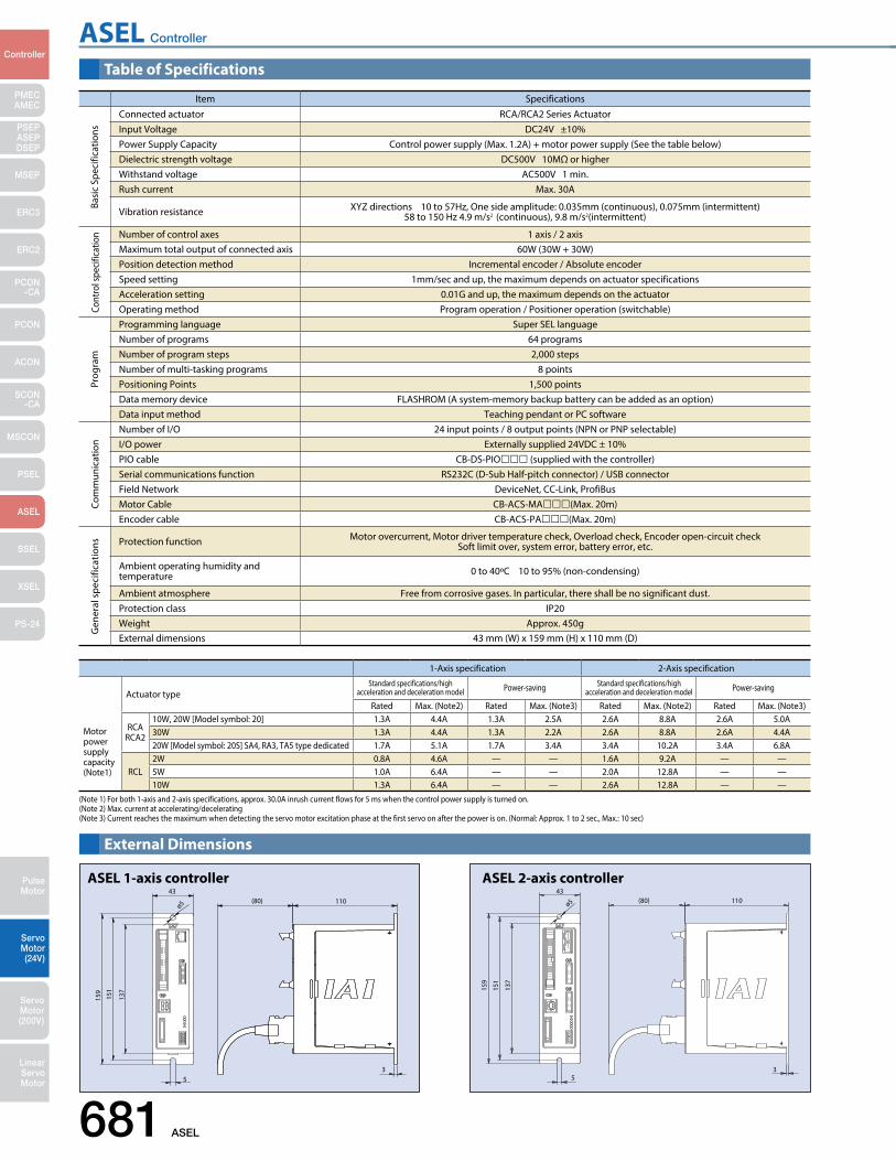
ASEL Controller
681 ASEL
PMECAMEC
Controller
Pulse Motor
Servo Motor (24V)
Servo Motor (200V)
LinearServo Motor
PSEP ASEPDSEP
MSEP
ERC3
ERC2
PCON-CA
PCON
ACON
SCON-CA
MSCON
PSEL
ASEL
SSEL
XSEL
PS-24
(80) 11043
ø5
159
151
137
53
External Dimensions
ASEL 1-axis controller
ø5
159
151
137
53
43(80) 110
ASEL 2-axis controller
1-Axis specification 2-Axis specification
Actuator typeStandard specifications/high
acceleration and deceleration model Power-saving Standard specifications/high acceleration and deceleration model Power-saving
Rated Max. (Note2) Rated Max. (Note3) Rated Max. (Note2) Rated Max. (Note3)
Motor power supplycapacity(Note1)
RCARCA2
10W, 20W [Model symbol: 20] 1.3A 4.4A 1.3A 2.5A 2.6A 8.8A 2.6A 5.0A30W 1.3A 4.4A 1.3A 2.2A 2.6A 8.8A 2.6A 4.4A20W [Model symbol: 20S] SA4, RA3, TA5 type dedicated 1.7A 5.1A 1.7A 3.4A 3.4A 10.2A 3.4A 6.8A
RCL2W 0.8A 4.6A — — 1.6A 9.2A — —5W 1.0A 6.4A — — 2.0A 12.8A — —10W 1.3A 6.4A — — 2.6A 12.8A — —
(Note 1) For both 1-axis and 2-axis specifications, approx. 30.0A inrush current flows for 5 ms when the control power supply is turned on.(Note 2) Max. current at accelerating/decelerating(Note 3) Current reaches the maximum when detecting the servo motor excitation phase at the first servo on after the power is on. (Normal: Approx. 1 to 2 sec., Max.: 10 sec)
Table of Specifications
Item SpecificationsConnected actuator RCA/RCA2 Series ActuatorInput Voltage DC24V ±10%Power Supply Capacity Control power supply (Max. 1.2A) + motor power supply (See the table below)Dielectric strength voltage DC500V 10MΩ or higherWithstand voltage AC500V 1 min.Rush current Max. 30A
Vibration resistance XYZ directions 10 to 57Hz, One side amplitude: 0.035mm (continuous), 0.075mm (intermittent) 58 to 150 Hz 4.9 m/s2 (continuous), 9.8 m/s2(intermittent)
Number of control axes 1 axis / 2 axisMaximum total output of connected axis 60W (30W + 30W)Position detection method Incremental encoder / Absolute encoderSpeed setting 1mm/sec and up, the maximum depends on actuator specificationsAcceleration setting 0.01G and up, the maximum depends on the actuatorOperating method Program operation / Positioner operation (switchable)Programming language Super SEL languageNumber of programs 64 programsNumber of program steps 2,000 stepsNumber of multi-tasking programs 8 pointsPositioning Points 1,500 pointsData memory device FLASHROM (A system-memory backup battery can be added as an option)Data input method Teaching pendant or PC softwareNumber of I/O 24 input points / 8 output points (NPN or PNP selectable)I/O power Externally supplied 24VDC ± 10%PIO cable CB-DS-PIO (supplied with the controller)Serial communications function RS232C (D-Sub Half-pitch connector) / USB connectorField Network DeviceNet, CC-Link, ProfiBusMotor Cable CB-ACS-MA(Max. 20m)Encoder cable CB-ACS-PA(Max. 20m)
Protection function Motor overcurrent, Motor driver temperature check, Overload check, Encoder open-circuit checkSoft limit over, system error, battery error, etc.
Ambient operating humidity and temperature 0 to 40ºC 10 to 95% (non-condensing)
Ambient atmosphere Free from corrosive gases. In particular, there shall be no significant dust.Protection class IP20Weight Approx. 450gExternal dimensions 43 mm (W) x 159 mm (H) x 110 mm (D)
Basi
c Sp
ecifi
catio
nsCo
ntro
l spe
cific
atio
nPr
ogra
mCo
mm
unic
atio
nG
ener
al s
peci
ficat
ions
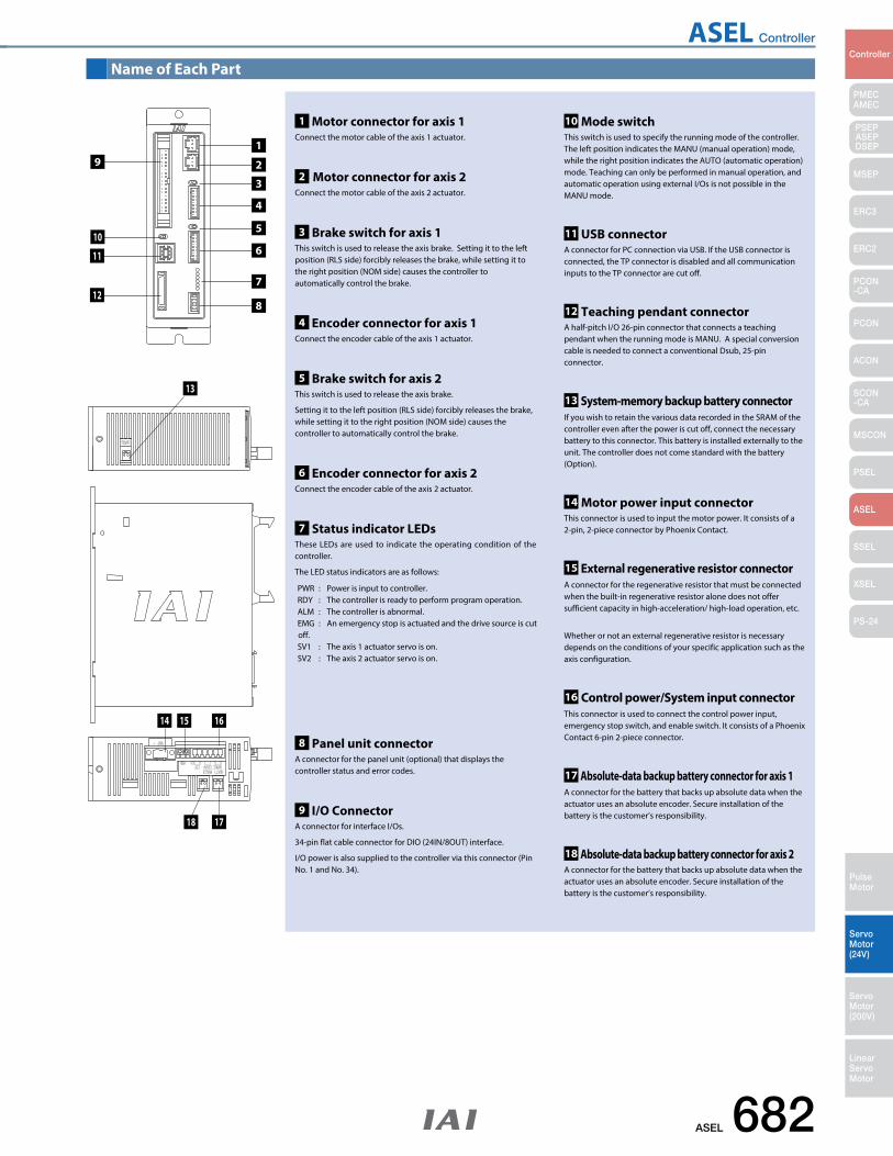
ASEL Controller
ASEL 682
PMECAMEC
Controller
Pulse Motor
Servo Motor (24V)
Servo Motor (200V)
LinearServo Motor
PSEP ASEPDSEP
MSEP
ERC3
ERC2
PCON-CA
PCON
ACON
SCON-CA
MSCON
PSEL
ASEL
SSEL
XSEL
PS-24
Name of Each Part
13
14
19
1 Motor connector for axis 1 Connect the motor cable of the axis 1 actuator.
8 Panel unit connector A connector for the panel unit (optional) that displays the controller status and error codes.
9 I/O Connector A connector for interface I/Os.
34-pin flat cable connector for DIO (24IN/8OUT) interface.
I/O power is also supplied to the controller via this connector (Pin No. 1 and No. 34).
10 Mode switch This switch is used to specify the running mode of the controller. The left position indicates the MANU (manual operation) mode, while the right position indicates the AUTO (automatic operation) mode. Teaching can only be performed in manual operation, and automatic operation using external I/Os is not possible in the MANU mode.
11 USB connectorA connector for PC connection via USB. If the USB connector is connected, the TP connector is disabled and all communication inputs to the TP connector are cut off.
12 Teaching pendant connectorA half-pitch I/O 26-pin connector that connects a teaching pendant when the running mode is MANU. A special conversion cable is needed to connect a conventional Dsub, 25-pin connector.
14 Motor power input connectorThis connector is used to input the motor power. It consists of a 2-pin, 2-piece connector by Phoenix Contact.
15 External regenerative resistor connectorA connector for the regenerative resistor that must be connected when the built-in regenerative resistor alone does not offer sufficient capacity in high-acceleration/ high-load operation, etc.
Whether or not an external regenerative resistor is necessary depends on the conditions of your specific application such as the axis configuration.
16 Control power/System input connectorThis connector is used to connect the control power input, emergency stop switch, and enable switch. It consists of a Phoenix Contact 6-pin 2-piece connector.
17 Absolute-data backup battery connector for axis 1A connector for the battery that backs up absolute data when the actuator uses an absolute encoder. Secure installation of the battery is the customer’s responsibility.
18 Absolute-data backup battery connector for axis 2A connector for the battery that backs up absolute data when the actuator uses an absolute encoder. Secure installation of the battery is the customer’s responsibility.
13 System-memory backup battery connectorIf you wish to retain the various data recorded in the SRAM of the controller even after the power is cut off, connect the necessary battery to this connector. This battery is installed externally to the unit. The controller does not come standard with the battery (Option).
2 Motor connector for axis 2 Connect the motor cable of the axis 2 actuator.
4 Encoder connector for axis 1Connect the encoder cable of the axis 1 actuator.
6 Encoder connector for axis 2Connect the encoder cable of the axis 2 actuator.
3 Brake switch for axis 1 This switch is used to release the axis brake. Setting it to the left position (RLS side) forcibly releases the brake, while setting it to the right position (NOM side) causes the controller to automatically control the brake.
5 Brake switch for axis 2 This switch is used to release the axis brake.
Setting it to the left position (RLS side) forcibly releases the brake, while setting it to the right position (NOM side) causes the controller to automatically control the brake.
7 Status indicator LEDsThese LEDs are used to indicate the operating condition of the controller.
The LED status indicators are as follows:
PWR : Power is input to controller.RDY : The controller is ready to perform program operation. ALM : The controller is abnormal. EMG : An emergency stop is actuated and the drive source is cut off. SV1 : The axis 1 actuator servo is on. SV2 : The axis 2 actuator servo is on.
10
11
12
2
3
4
5
6
8
7
15 16
1718
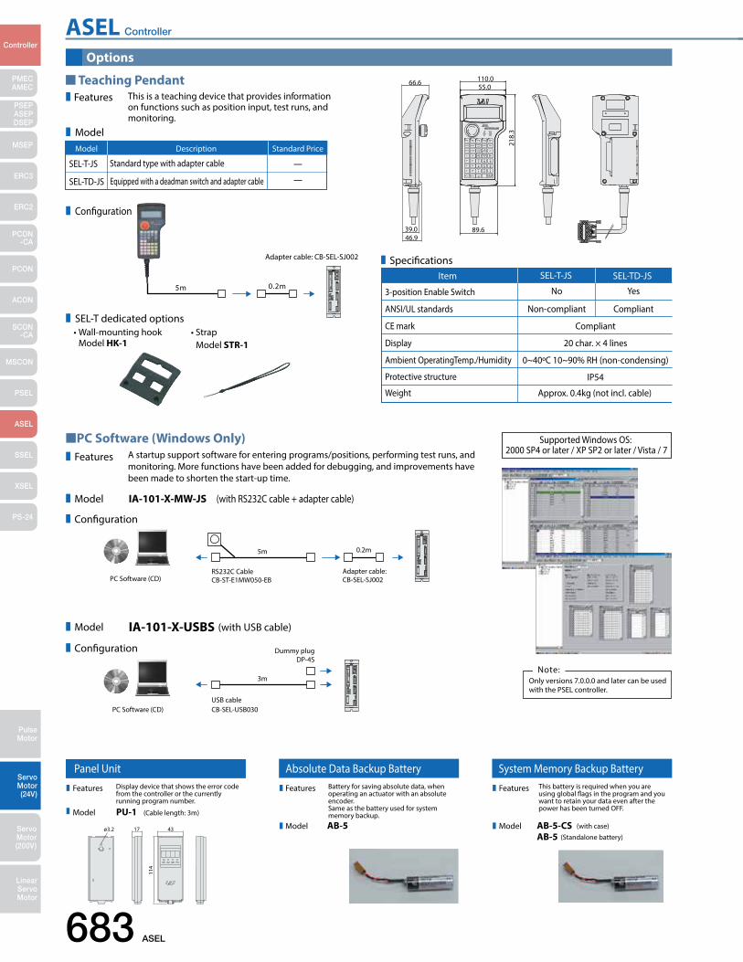
683 ASEL
PMECAMEC
Controller
Pulse Motor
Servo Motor (24V)
Servo Motor (200V)
LinearServo Motor
PSEP ASEPDSEP
MSEP
ERC3
ERC2
PCON-CA
PCON
ACON
SCON-CA
MSCON
PSEL
ASEL
SSEL
XSEL
PS-24
ASEL Controller
Options
Teaching Pendant
PC Software (Windows Only)
• Wall-mounting hook Model HK-1
• Strap Model STR-1
Features This is a teaching device that provides information on functions such as position input, test runs, and monitoring.
A startup support software for entering programs/positions, performing test runs, and monitoring. More functions have been added for debugging, and improvements have been made to shorten the start-up time.
IA-101-X-MW-JS (with RS232C cable + adapter cable)
Specifications
5m
5m
Adapter cable: CB-SEL-SJ002
0.2m
0.2m
Adapter cable: CB-SEL-SJ002PC Software (CD)
RS232C CableCB-ST-E1MW050-EB
IA-101-X-USBS (with USB cable)
3m
Dummy plugDP-4S
PC Software (CD)USB cableCB-SEL-USB030
Only versions 7.0.0.0 and later can be used with the PSEL controller.
Note:
Features
Model
Configuration
Model
Configuration
66.6
46.939.0
55.0
89.6
218.
3
110.0
Model
Configuration
SEL-T dedicated options
SEL-T-JS —
—
Standard type with adapter cable
Equipped with a deadman switch and adapter cable
Model Description Standard Price
SEL-TD-JS
Supported Windows OS: 2000 SP4 or later / XP SP2 or later / Vista / 7
3-position Enable Switch No Yes
Compliant
Item SEL-T-JS SEL-TD-JS
ANSI/UL standards
CE mark
Display
Ambient OperatingTemp./Humidity
Protective structure
Weight
Non-compliant Compliant
20 char. × 4 lines
0~40ºC 10~90% RH (non-condensing)
IP54
Approx. 0.4kg (not incl. cable)
Panel UnitDisplay device that shows the error code from the controller or the currently running program number.
PU-1 (Cable length: 3m)
Dummy Plug
When connecting the ASEL controller to a computer with a USB cable, this plug is inserted in the teaching port to shut o the enable circuit. (Supplied with the PC software IA-101-X-USB)
A cable for connecting the controller to the USB port to a computer. A controller with no USB port (e.g. XSEL) can be connected to the USB port of a computer by connecting an RS232C cable to the USB cable via a USB adapter. (See PC software IA-101-X-USBMW)
DP-4S
USB Cable Adapter Cable
CB-SEL-USB030 (Cable length: 3m)
An adapter cable to connect the D-sub 25-pin connector from the teaching pendant or a PC to the teaching connector (half-pitch) of the ASEL controller.
CB-SEL-SJ002 (Cable length: 0.2m)
ø3.2 17
114
43
Battery for saving absolute data, when operating an actuator with an absolute encoder. Same as the battery used for system memory backup.AB-5
Absolute Data Backup Battery System Memory Backup BatteryThis battery is required when you are using global ags in the program and you want to retain your data even after the power has been turned OFF.
AB-5AB-5-CS
(Standalone battery)
(with case)
Features
Model
Features
Model
Features
Model
Features
Model
Features
Model
Features
Model
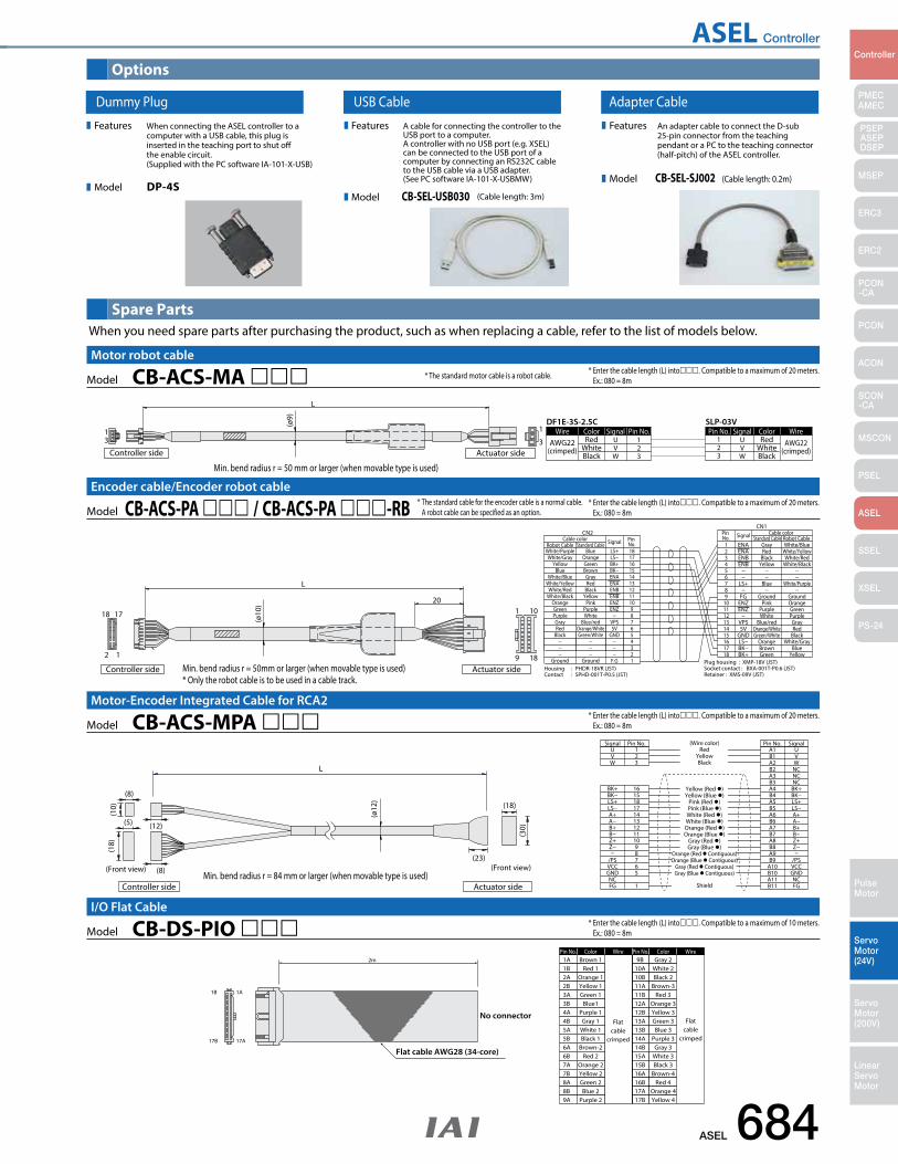
ASEL 684
PMECAMEC
Controller
Pulse Motor
Servo Motor (24V)
Servo Motor (200V)
LinearServo Motor
PSEP ASEPDSEP
MSEP
ERC3
ERC2
PCON-CA
PCON
ACON
SCON-CA
MSCON
PSEL
ASEL
SSEL
XSEL
PS-24
ASEL Controller
Panel UnitDisplay device that shows the error code from the controller or the currently running program number.
PU-1 (Cable length: 3m)
Dummy Plug
When connecting the ASEL controller to a computer with a USB cable, this plug is inserted in the teaching port to shut o the enable circuit. (Supplied with the PC software IA-101-X-USB)
A cable for connecting the controller to the USB port to a computer. A controller with no USB port (e.g. XSEL) can be connected to the USB port of a computer by connecting an RS232C cable to the USB cable via a USB adapter. (See PC software IA-101-X-USBMW)
DP-4S
USB Cable Adapter Cable
CB-SEL-USB030 (Cable length: 3m)
An adapter cable to connect the D-sub 25-pin connector from the teaching pendant or a PC to the teaching connector (half-pitch) of the ASEL controller.
CB-SEL-SJ002 (Cable length: 0.2m)
ø3.2 17
114
43
Battery for saving absolute data, when operating an actuator with an absolute encoder. Same as the battery used for system memory backup.AB-5
Absolute Data Backup Battery System Memory Backup BatteryThis battery is required when you are using global ags in the program and you want to retain your data even after the power has been turned OFF.
AB-5AB-5-CS
(Standalone battery)
(with case)
Features
Model
Features
Model
Features
Model
Features
Model
Features
Model
Features
Model
Spare Parts
Options
When you need spare parts after purchasing the product, such as when replacing a cable, refer to the list of models below.
ColorPin No. Wire
Flatcable
crimped
Wire
Flatcable
crimped
ColorPin No.1A Brown 1 9B Gray 2
1B 1A
2m
17B 17A
Flat cable AWG28 (34-core)
No connector
1B2A2B3A3B4A4B5A5B6A6B7A7B8A8B9A
Red 1Orange 1Yellow 1Green 1
Blue1Purple 1Gray 1
White 1Black 1
Brown-2Red 2
Orange 2Yellow 2Green 2Blue 2
Purple 2
10A10B11A11B12A12B13A13B14A14B15A15B16A16B17A17B
White 2Black 2
Brown-3Red 3
Orange 3Yellow 3Green 3Blue 3
Purple 3Gray 3
White 3Black 3
Brown-4Red 4
Orange 4Yellow 4
Model CB-DS-PIO I/O Flat Cable
* Enter the cable length (L) into. Compatible to a maximum of 10 meters. Ex.: 080 = 8m
White/Purple Blue LS+ 181 ENA Gray White/BlueRobot Cable Standard Cable
Housing : PHDR-18VR (JST)Contact : SPHD-001T-P0.5 (JST)
Plug housing : XMP-18V (JST)Socket contact : BXA-001T-P0.6 (JST)Retainer : XMS-09V (JST)
CN2CN1
Pin No.
Cable color Signal Robot CableStandard CableCable color
1
9 18
1020
18
2 1
17
Actuator sideController side
L
(ø10
)
White/GrayYellow
BlueWhite/Blue
White/YellowWhite/Red
White/BlackOrangeGreenPurpleGrayRed
Black
Ground
OrangeGreenBrownGrayRed
BlackYellow
PinkPurpleWhite
Blue/redOrange/WhiteGreen/White
Ground
LS−BK+BK−ENAENAENBENBENZENZ
VPS5V
GND
F.G
1716151413121110987654321
23456789
101112131415161718
ENAENBENB
−−
LS+−
FGENZENZ
−VPS5V
GNDLS−BK−BK+
RedBlack
Yellow
Blue
GroundPink
PurpleWhite
Blue/redOrange/WhiteGreen/White
OrangeBrownGreen
White/YellowWhite/Red
White/Black
White/Purple
GroundOrangeGreenPurpleGrayRed
BlackWhite/Gray
BlueYellow
Pin No. Signal
* Enter the cable length (L) into. Compatible to a maximum of 20 meters. Ex.: 080 = 8mModel CB-ACS-PA / CB-ACS-PA -RB
Encoder cable/Encoder robot cable * The standard cable for the encoder cable is a normal cable. A robot cable can be specified as an option.
Min. bend radius r = 50mm or larger (when movable type is used)* Only the robot cable is to be used in a cable track.
* Enter the cable length (L) into. Compatible to a maximum of 20 meters. Ex.: 080 = 8m
BK−LS+LS−A+A−B+B−Z+Z−
/PSVCCGNDNCFG
L
UVW
Shield
Yellow (Red )Yellow (Blue )
Pink (Red )Pink (Blue )
White (Red )White (Blue )Orange (Red )Orange (Blue )
Gray (Red )Gray (Blue )
Orange (Red Contiguous)Orange (Blue Contiguous)
Gray (Red Contiguous)Gray (Blue Contiguous)
RedYellowBlack
(Wire color)123
A1 USignal Pin No. Pin No. Signal
BK+ 16
(10)
(ø12
)
(18)
(8)
(12)
(23)
(8)
(5)
(30)
(18)
Controller side
(Front view)
Actuator side
(Front view)
151817141312111098765
1
B1A2B2A3B3A4B4A5B5A6B6A7B7A8B8A9B9
A10B10A11B11
VWNCNCNC
BK+BK−LS+LS−A+A−B+B−Z+Z−
/PSVCCGNDNCFG
Model CB-ACS-MPA Motor-Encoder Integrated Cable for RCA2
Min. bend radius r = 84 mm or larger (when movable type is used)
AWG22(crimped) White
Wire Color Signal Pin No. Pin No.U 1
Signal Color WireRed 1
23Black
VW
23 W
VU Red
WhiteBlack
AWG22(crimped)
DF1E-3S-2.5C SLP-03V13 3
1
L
Actuator sideController side
(ø9)
Model CB-ACS-MA Motor robot cable
* Enter the cable length (L) into. Compatible to a maximum of 20 meters. Ex.: 080 = 8m* The standard motor cable is a robot cable.
Min. bend radius r = 50 mm or larger (when movable type is used)
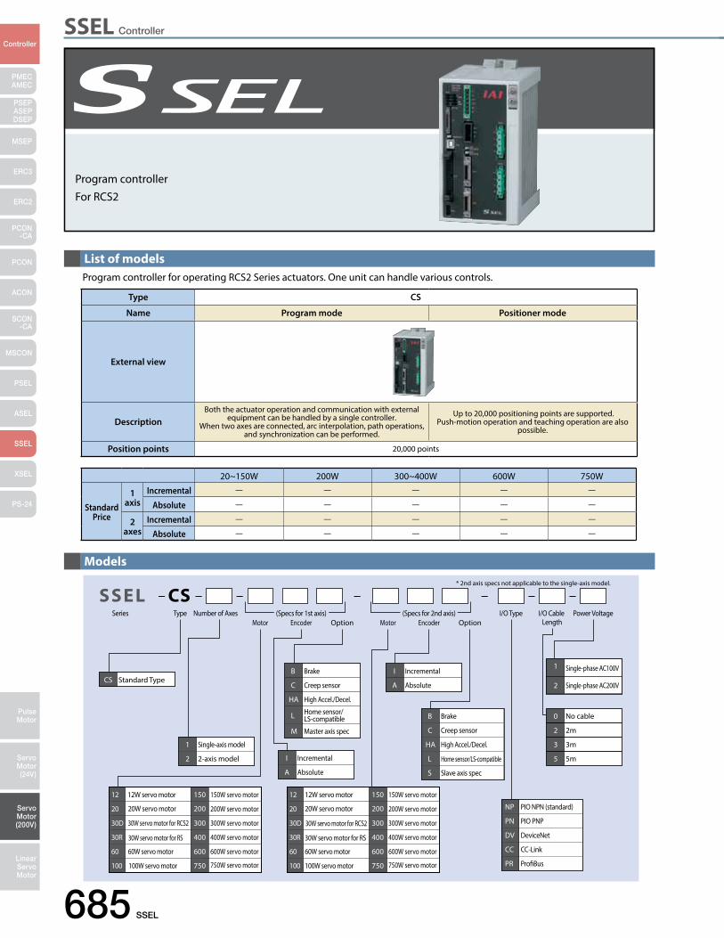
SSEL Controller
685 SSEL
PMECAMEC
Controller
Pulse Motor
Servo Motor (24V)
Servo Motor (200V)
LinearServo Motor
PSEP ASEPDSEP
MSEP
ERC3
ERC2
PCON-CA
PCON
ACON
SCON-CA
MSCON
PSEL
ASEL
SSEL
XSEL
PS-24
Program controllerFor RCS2
List of models
Models
Type Number of AxesMotor Encoder Option Motor Encoder Option
I/O Cable Length
Power Voltage
* 2nd axis specs not applicable to the single-axis model.
I/O Type
B Brake
C Creep sensor
HA High Accel./Decel.
L Home sensor/LS-compatible
M Master axis spec
B Brake
C Creep sensor
HA High Accel./Decel.
L Home sensor/LS-compatible
S Slave axis spec
12 12W servo motor
20 20W servo motor
30D 30W servo motor for RCS2
30R 30W servo motor for RS
60 60W servo motor
100 100W servo motor
150
200
150W servo motor
200W servo motor
300
400
300W servo motor
400W servo motor
600
750
600W servo motor
750W servo motor
12 12W servo motor
20 20W servo motor
30D 30W servo motor for RCS2
30R 30W servo motor for RS
60 60W servo motor
100 100W servo motor
150
200
150W servo motor
200W servo motor
300
400
300W servo motor
400W servo motor
600
750
600W servo motor
750W servo motor
1 Single-axis model
2 2-axis model I Incremental
A Absolute
I Incremental
A Absolute
NP PIO NPN (standard)
PN PIO PNP
DV DeviceNet
CC CC-Link
PR ProBus
1 Single-phase AC100V
2 Single-phase AC200V
0 No cable
2 2m
3 3m
5 5m
CS Standard Type
CSSSELSeries (Specs for 1st axis) (Specs for 2nd axis)
20~150W 200W 300~400W 600W 750W
Standard Price
1 axis
Incremental — — — — —
Absolute — — — — —
2 axes
Incremental — — — — —
Absolute — — — — —
Program controller for operating RCS2 Series actuators. One unit can handle various controls.
Type CS
Name Program mode Positioner mode
External view
DescriptionBoth the actuator operation and communication with external
equipment can be handled by a single controller.When two axes are connected, arc interpolation, path operations,
and synchronization can be performed.
Up to 20,000 positioning points are supported. Push-motion operation and teaching operation are also
possible.
Position points 20,000 points
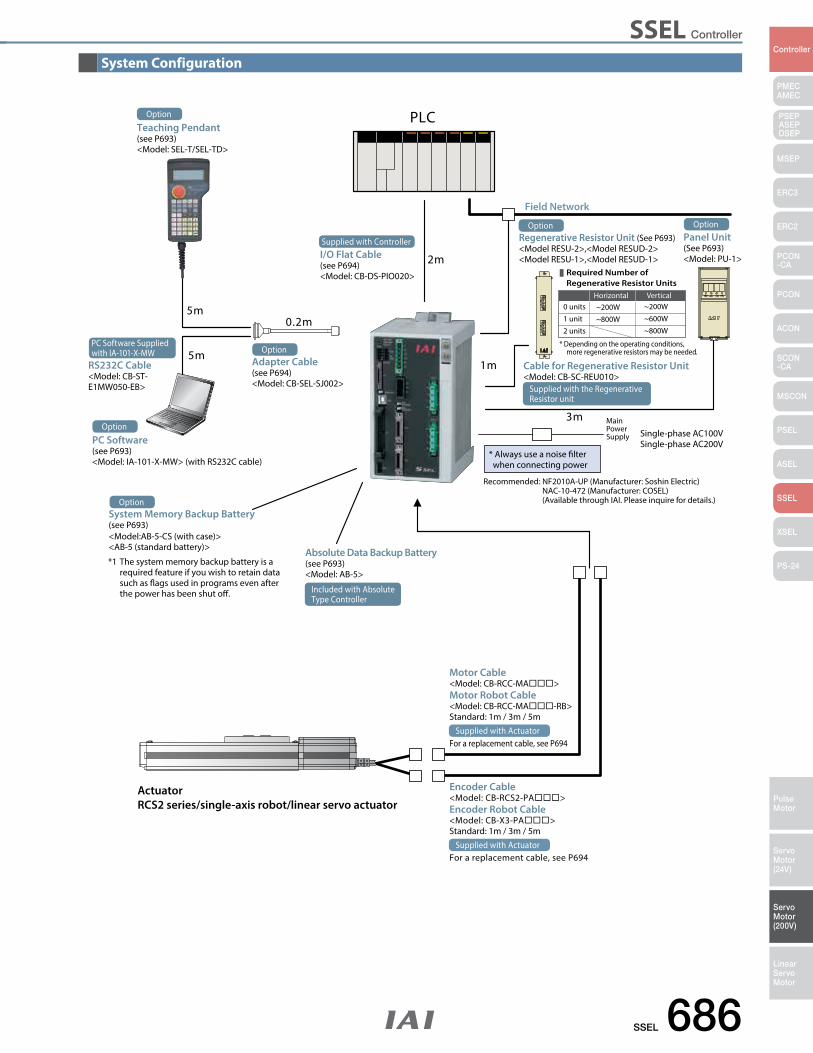
SSEL Controller
SSEL 686
PMECAMEC
Controller
Pulse Motor
Servo Motor (24V)
Servo Motor (200V)
LinearServo Motor
PSEP ASEPDSEP
MSEP
ERC3
ERC2
PCON-CA
PCON
ACON
SCON-CA
MSCON
PSEL
ASEL
SSEL
XSEL
PS-24
PLC
I/O Flat Cable(see P694)<Model: CB-DS-PIO020>
Absolute Data Backup Battery(see P693)<Model: AB-5>
Teaching Pendant(see P693)<Model: SEL-T/SEL-TD>
0.2m5m
5m
ActuatorRCS2 series/single-axis robot/linear servo actuator
2m
1m
3m
<Model:AB-5-CS (with case)><AB-5 (standard battery)>
*1 The system memory backup battery is a required feature if you wish to retain data such as ags used in programs even after the power has been shut o.
Main Power Supply Single-phase AC100V
Single-phase AC200V
Recommended: NF2010A-UP (Manufacturer: Soshin Electric) NAC-10-472 (Manufacturer: COSEL) (Available through IAI. Please inquire for details.)
* Always use a noise lter when connecting power
Field Network
Required Number of Regenerative Resistor Units
0 units ~200WHorizontal
~200WVertical
* Depending on the operating conditions, more regenerative resistors may be needed.
1 unit
2 units~800W ~600W
~800W
Option
PC Software(see P693)<Model: IA-101-X-MW> (with RS232C cable)
Option
System Memory Backup Battery (see P693)
Option
Motor Cable<Model: CB-RCC-MA>Motor Robot Cable<Model: CB-RCC-MA-RB>Standard: 1m / 3m / 5m
For a replacement cable, see P694Supplied with Actuator
Regenerative Resistor Unit (See P693)<Model RESU-2>,<Model RESUD-2><Model RESU-1>,<Model RESUD-1>
Option
Adapter Cable(see P694)<Model: CB-SEL-SJ002>
Option
Panel Unit(See P693)<Model: PU-1>
Option
Supplied with Controller
RS232C Cable<Model: CB-ST-E1MW050-EB>
PC Software Suppliedwith IA-101-X-MW
Included with AbsoluteType Controller
Cable for Regenerative Resistor Unit<Model: CB-SC-REU010>
Supplied with the RegenerativeResistor unit
Encoder Cable<Model: CB-RCS2-PA>Encoder Robot Cable<Model: CB-X3-PA>Standard: 1m / 3m / 5m
For a replacement cable, see P694Supplied with Actuator
System Configuration
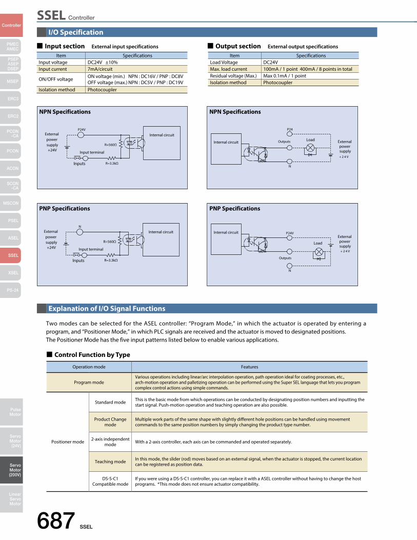
SSEL Controller
687 SSEL
PMECAMEC
Controller
Pulse Motor
Servo Motor (24V)
Servo Motor (200V)
LinearServo Motor
PSEP ASEPDSEP
MSEP
ERC3
ERC2
PCON-CA
PCON
ACON
SCON-CA
MSCON
PSEL
ASEL
SSEL
XSEL
PS-24
I/O Specification
Explanation of I/O Signal Functions
Input section External input specifications Output section External output specifications
Item SpecificationsInput voltage DC24V ±10%Input current 7mA/circuit
ON/OFF voltage ON voltage (min.) NPN : DC16V / PNP : DC8VOFF voltage (max.) NPN : DC5V / PNP : DC19V
Isolation method Photocoupler
Item SpecificationsLoad Voltage DC24VMax. load current 100mA / 1 point 400mA / 8 points in totalResidual voltage (Max.) Max 0.1mA / 1 pointIsolation method Photocoupler
Control Function by Type
Operation mode Features
Program modeVarious operations including linear/arc interpolation operation, path operation ideal for coating processes, etc., arch-motion operation and palletizing operation can be performed using the Super SEL language that lets you program complex control actions using simple commands.
Positioner mode
Standard mode This is the basic mode from which operations can be conducted by designating position numbers and inputting the start signal. Push-motion operation and teaching operation are also possible.
Product Change mode
Multiple work parts of the same shape with slightly different hole positions can be handled using movement commands to the same position numbers by simply changing the product type number.
2-axis independent mode With a 2-axis controller, each axis can be commanded and operated separately.
Teaching mode In this mode, the slider (rod) moves based on an external signal, when the actuator is stopped, the current location can be registered as position data.
DS-S-C1Compatible mode
If you were using a DS-S-C1 controller, you can replace it with a ASEL controller without having to change the host programs. *This mode does not ensure actuator compatibility.
Two modes can be selected for the ASEL controller: “Program Mode,” in which the actuator is operated by entering a program, and “Positioner Mode,” in which PLC signals are received and the actuator is moved to designated positions. The Positioner Mode has the five input patterns listed below to enable various applications.
P24V
R=3.3kΩInputs
R=560Ω
External power supply+24V Input terminal
Internal circuit
NPN Specifications
P24
N
Outputs Internal circuit Load External power supply+ 2 4 V
NPN Specifications
N
R=3.3kΩInputs
R=560Ω
External power supply+24V Input terminal
Internal circuit
PNP Specifications
P24V
N
Outputs
Internal circuitExternal power supply+ 2 4 V
Load
PNP Specifications
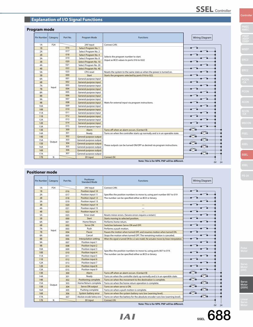
SSEL Controller
SSEL 688
PMECAMEC
Controller
Pulse Motor
Servo Motor (24V)
Servo Motor (200V)
LinearServo Motor
PSEP ASEPDSEP
MSEP
ERC3
ERC2
PCON-CA
PCON
ACON
SCON-CA
MSCON
PSEL
ASEL
SSEL
XSEL
PS-24
Explanation of I/O Signal Functions
Pin Number Category
Input
Output
N
01624V input Connect 24V.
Port No. PositionerStandard Mode Functions
Resets minor errors. (Severe errors require a restart.)
———
Turns o when an alarm occurs. (Contact B)Turns on when the controller starts up normally and is in an operable state.Turns on when the movement to the destination is complete.Turns on when the home return operation is complete.Turns on when servo is ON.Turns on when a push motion is complete.Turns on when the system battery runs low (warning level).Turns on when the battery for the absolute encoder runs low (warning level).Connect 0V.
Starts moving to selected position.Performs home return.Switches between Servo ON and OFF.Performs a push motion.Pauses the motion when turned OFF, and resumes motion when turned ON.Stops the motion when turned OFF. The remaining motion is canceled.When this signal is turned ON for a 2-axis model, the actuator moves by linear interpolation.
Species the position numbers to move to, using ports 007 to 019. The number can be specied either as BCD or binary.
Species the position numbers to move to, using port number 007 to 019 The number can be specied either as BCD or binary.
0V 24
Wiring Diagram
1A P241B2A2B3A3B4A4B5A5B6A6B7A7B8A8B9A9B
10A10B11A11B12A12B13A13B14A14B15A15B16A16B17A17B
017018019020021022023000001002003004005006007008009010011012013014015300301302303304305306307
Position input 10Position input 11Position input 12Position input 13Position input 14Position input 15Position input 16
Error resetStart
Home ReturnServo ON
PushPauseCancel
Interpolation settingPosition input 1Position input 2Position input 3Position input 4Position input 5Position input 6Position input 7Position input 8Position input 9
AlarmReady
Positioning completeHome Return complete
Servo ON outputPushing complete
System battery errorAbsolute encoder battery error
0V input
Positioner mode
Note: This is for NPN. PNP will be different.
Pin Number Category
Input
Output
N
01624V input Connect 24V.
Port No. Program Mode Functions
Resets the system to the same state as when the power is turned on.
Turns o when an alarm occurs. (Contact B)Turns on when the controller starts up normally and is in an operable state.
Connect 0V.
These outputs can be turned ON/OFF as desired via program instructions.
Starts the programs selected by ports 016 to 022.
Waits for external input via program instructions.
Selects the program number to start. (Input as BCD values to ports 016 to 022)
0V 24
Wiring Diagram
1A P241B2A2B3A3B4A4B5A5B6A6B7A7B8A8B9A9B
10A10B11A11B12A12B13A13B14A14B15A15B16A16B17A17B
017018019020021022023000001002003004005006007008009010011012013014015300301302303304305306307
Select Program No. 1Select Program No. 2Select Program No. 4Select Program No. 8
Select Program No. 10Select Program No. 20Select Program No. 40
CPU resetStart
General-purpose inputGeneral-purpose inputGeneral-purpose inputGeneral-purpose inputGeneral-purpose inputGeneral-purpose inputGeneral-purpose inputGeneral-purpose inputGeneral-purpose inputGeneral-purpose inputGeneral-purpose inputGeneral-purpose inputGeneral-purpose inputGeneral-purpose inputGeneral-purpose input
AlarmReady
General-purpose outputGeneral-purpose outputGeneral-purpose outputGeneral-purpose outputGeneral-purpose outputGeneral-purpose output
0V input
Program mode
Note: This is for NPN. PNP will be different.

SSEL Controller
689 SSEL
PMECAMEC
Controller
Pulse Motor
Servo Motor (24V)
Servo Motor (200V)
LinearServo Motor
PSEP ASEPDSEP
MSEP
ERC3
ERC2
PCON-CA
PCON
ACON
SCON-CA
MSCON
PSEL
ASEL
SSEL
XSEL
PS-24
Explanation of I/O Signal Functions
Pin Number Category
Input
Output
N
01624V input Connect 24V.
Port No. Positioner Product Type Change Mode Functions
Connect 0V.
0V 24
Wiring Diagram
1A P24
Resets minor errors. (Severe errors require a restart.)
Turns o when an alarm occurs. (Contact B)Turns on when the controller starts up normally and is in an operable state.Turns on when the movement to the destination is complete.Turns on when the home return operation is complete.Turns on when servo is ON.Turns on when a push motion is complete.Turns on when the system battery runs low (warning level).Turns on when the battery for the absolute encoder runs low (warning level).
Starts moving to selected position.Performs home return.Switches between Servo ON and OFF.Performs a push motion.Pauses the motion when turned OFF, and resumes motion when turned ON.Stops the motion when turned OFF. The remaining motion is canceled.When this signal is turned ON for a 2-axis model, the actuator moves by linear interpolation.
Species the position numbers to move to, and the product type numbers,using ports 007 to 022. The position and product type numbers are assigned by parameter settings. The number can be specied either as BCD or binary.
Species the position numbers to move to, and the product type numbers, using ports 007 to 022. The position and product type numbers are assigned by parameter settings. The number can be specied either as BCD or binary.
1B2A2B3A3B4A4B5A5B6A6B7A7B8A8B9A9B
10A10B11A11B12A12B13A13B14A14B15A15B16A16B17A17B
017018019020021022023000001002003004005006007008009010011012013014015300301302303304305306307
Position/Product Type Input 10Position/Product Type Input 11Position/Product Type Input 12Position/Product Type Input 13Position/Product Type Input 14Position/Product Type Input 15Position/Product Type Input 16
Error resetStart
Home ReturnServo ON
PushPauseCancel
Interpolation settingPosition/Product Type Input 1Position/Product Type Input 2Position/Product Type Input 3Position/Product Type Input 4Position/Product Type Input 5Position/Product Type Input 6Position/Product Type Input 7Position/Product Type Input 8Position/Product Type Input 9
AlarmReady
Positioning completeHome Return completeServo ON output
Pushing completeSystem battery error
Absolute encoder battery error0V input
Positioner, Product-Type Change Mode
Note: This is for NPN. PNP will be different.
Pin Number Category
Input
Output
N
01624V input Connect 24V.
Port No. Positioner Independent Mode Functions
Connect 0V.
0V 24
Wiring Diagram
1A P24
Resets minor errors. (Severe errors require a restart.)
Turns o when an alarm occurs. (Contact B)Turns on when the controller starts up normally and is in an operable state.Turns on when the movement to the specied position on the 1st axis is complete.Turns on when home return on the 1st axis is complete.Turns on when the 1st axis is in a servo ON state.Turns on when the movement to the specied position on the 2nd axis is complete.Turns on when home return on the 2nd axis is complete.Turns on when the 2nd axis is in a servo ON state.
Starts the movement to the selected position number on the 1st axis.Performs Home Return on the 1st axis.Switches between servo ON and OFF for the 1st axis.
Cancels the movement on the 1st axis.Starts the movement to the selected position number on the 2nd axis.Performs Home Return on the 2nd axis.Switches between servo ON and OFF for the 2nd axis.
Cancels the movement on the 2nd axis.
Species the position numbers to move to, using ports 010 to 022. The position numbers on the 1st and 2nd axes are assigned by parameter settings. The number can be specied either as BCD or binary.
Species the position numbers to move to, using ports 010 to 022. The position numbers on the 1st and 2nd axes are assigned by parameter settings. The number can be specied either as BCD or binary.
Pauses the motion on 1st axis when turned OFF, and resumes when turned ON.
Pauses the motion on 2nd axis when turned OFF, and resumes when turned ON.
1B2A2B3A3B4A4B5A5B6A6B7A7B8A8B9A9B
10A10B11A11B12A12B13A13B14A14B15A15B16A16B17A17B
017018019020021022023000001002003004005006007008009010011012013014015300301302303304305306307
Position input 7Position input 8Position input 9
Position input 10Position input 11Position input 12Position input 13
Error resetStart 1
Home Return 1Servo ON 1
Pause 1Cancel 1Start 2
Home Return 2Servo ON 2
Pause 2Cancel 2
Position input 1Position input 2Position input 3Position input 4Position input 5Position input 6
AlarmReady
Positioning complete 1Home Return complete 1
Servo ON output 1Positioning complete 2Home Return complete 2
Servo ON output 20V input
Positioner, 2-axis Independent Mode
Note: This is for NPN. PNP will be different.
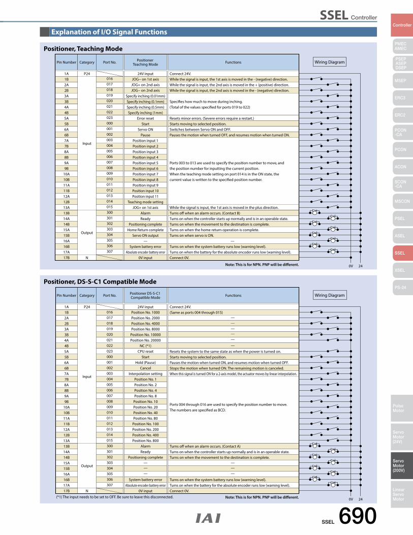
SSEL Controller
SSEL 690
PMECAMEC
Controller
Pulse Motor
Servo Motor (24V)
Servo Motor (200V)
LinearServo Motor
PSEP ASEPDSEP
MSEP
ERC3
ERC2
PCON-CA
PCON
ACON
SCON-CA
MSCON
PSEL
ASEL
SSEL
XSEL
PS-24
Pin Number Category
Input
Output
N
01624V input Connect 24V.
(Same as ports 004 through 015)
Port No. Positioner DS-S-C1 Compatible Mode Functions
Connect 0V.
0V 24
Wiring Diagram
1A P24
Resets the system to the same state as when the power is turned on.
Turns o when an alarm occurs. (Contact A)Turns on when the controller starts up normally and is in an operable state.Turns on when the movement to the destination is complete.
Turns on when the system battery runs low (warning level).Turns on when the battery for the absolute encoder runs low (warning level).
Starts moving to selected position.Pauses the motion when turned ON, and resumes motion when turned OFF.Stops the motion when turned ON. The remaining motion is canceled.When this signal is turned ON for a 2-axis model, the actuator moves by linear interpolation.
Ports 004 through 016 are used to specify the position number to move. The numbers are specied as BCD.
(*1) The input needs to be set to OFF. Be sure to leave this disconnected.
1B2A2B3A3B4A4B5A5B6A6B7A7B8A8B9A9B
10A10B11A11B12A12B13A13B14A14B15A15B16A16B17A17B
017018019020021022023000001002003004005006007008009010011012013014015300301302303304305306307
Position No. 1000Position No. 2000Position No. 4000Position No. 8000
Position No. 10000Position No. 20000
NC (*1)CPU reset
StartHold (Pause)
CancelInterpolation setting
Position No. 1Position No. 2Position No. 4Position No. 8
Position No. 10Position No. 20Position No. 40Position No. 80
Position No. 100Position No. 200Position No. 400Position No. 800
AlarmReady
Positioning complete
System battery error
———
—
—
—————
——
Absolute encoder battery error0V input
Explanation of I/O Signal Functions
Pin Number Category
Input
Output
N
01624V input Connect 24V.
While the signal is input, the 1st axis is moved in the - (negative) direction.While the signal is input, the 2nd axis is moved in the + (positive) direction.While the signal is input, the 2nd axis is moved in the - (negative) direction.
Species how much to move during inching. (Total of the values specied for ports 019 to 022)
Port No. Positioner Teaching Mode Functions
Connect 0V.
0V 24
Wiring Diagram
1A P24
Resets minor errors. (Severe errors require a restart.)
Turns o when an alarm occurs. (Contact B)While the signal is input, the 1st axis is moved in the plus direction.
Turns on when the controller starts up normally and is in an operable state.Turns on when the movement to the destination is complete.Turns on when the home return operation is complete.Turns on when servo is ON.
Turns on when the system battery runs low (warning level).Turns on when the battery for the absolute encoder runs low (warning level).
Starts moving to selected position.Switches between Servo ON and OFF.Pauses the motion when turned OFF, and resumes motion when turned ON.
Ports 003 to 013 are used to specify the position number to move, and the position number for inputting the current position. When the teaching mode setting on port 014 is in the ON state, the current value is written to the specied position number.
1B2A2B3A3B4A4B5A5B6A6B7A7B8A8B9A9B
10A10B11A11B12A12B13A13B14A14B15A15B16A16B17A17B
017018019020021022023000001002003004005006007008009010011012013014015300301302303304305306307
JOG− on 1st axisJOG+ on 2nd axisJOG− on 2nd axis
Specify inching (0.01mm)Specify inching (0.1mm)Specify inching (0.5mm)Specify inching (1mm)
Error resetStart
Servo ONPause
Position input 1Position input 2Position input 3Position input 4Position input 5Position input 6Position input 7Position input 8Position input 9Position input 10Position input 11
Teaching mode settingJOG+ on 1st axis
AlarmReady
Positioning completeHome Return complete
Servo ON output— —
System battery errorAbsolute encoder battery error
0V input
Positioner, Teaching Mode
Positioner, DS-S-C1 Compatible Mode
Note: This is for NPN. PNP will be different.
Note: This is for NPN. PNP will be different.
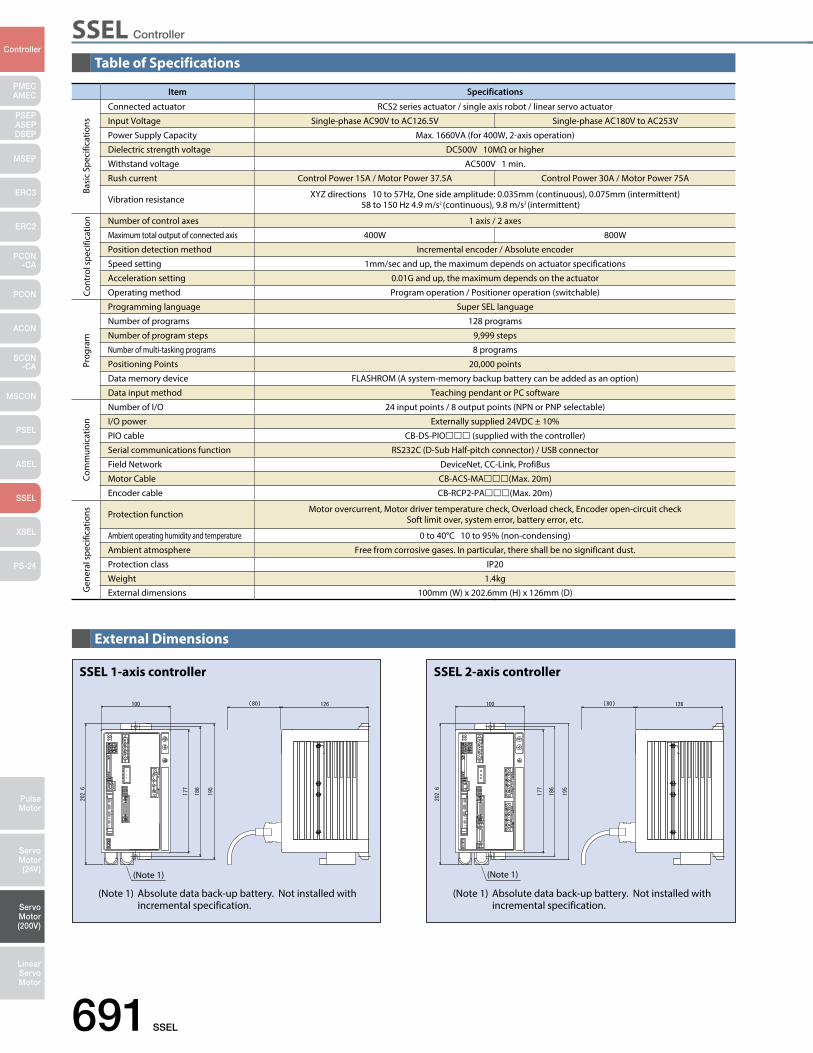
SSEL Controller
691 SSEL
PMECAMEC
Controller
Pulse Motor
Servo Motor (24V)
Servo Motor (200V)
LinearServo Motor
PSEP ASEPDSEP
MSEP
ERC3
ERC2
PCON-CA
PCON
ACON
SCON-CA
MSCON
PSEL
ASEL
SSEL
XSEL
PS-24
Table of Specifications
External Dimensions
Item Specifications
Connected actuator RCS2 series actuator / single axis robot / linear servo actuator
Input Voltage Single-phase AC90V to AC126.5V Single-phase AC180V to AC253V
Power Supply Capacity Max. 1660VA (for 400W, 2-axis operation)
Dielectric strength voltage DC500V 10MΩ or higher
Withstand voltage AC500V 1 min.
Rush current Control Power 15A / Motor Power 37.5A Control Power 30A / Motor Power 75A
Vibration resistance XYZ directions 10 to 57Hz, One side amplitude: 0.035mm (continuous), 0.075mm (intermittent) 58 to 150 Hz 4.9 m/s2 (continuous), 9.8 m/s2 (intermittent)
Number of control axes 1 axis / 2 axes
Maximum total output of connected axis 400W 800W
Position detection method Incremental encoder / Absolute encoder
Speed setting 1mm/sec and up, the maximum depends on actuator specifications
Acceleration setting 0.01G and up, the maximum depends on the actuator
Operating method Program operation / Positioner operation (switchable)
Programming language Super SEL language
Number of programs 128 programs
Number of program steps 9,999 steps
Number of multi-tasking programs 8 programs
Positioning Points 20,000 points
Data memory device FLASHROM (A system-memory backup battery can be added as an option)
Data input method Teaching pendant or PC software
Number of I/O 24 input points / 8 output points (NPN or PNP selectable)
I/O power Externally supplied 24VDC ± 10%
PIO cable CB-DS-PIO (supplied with the controller)
Serial communications function RS232C (D-Sub Half-pitch connector) / USB connector
Field Network DeviceNet, CC-Link, ProfiBus
Motor Cable CB-ACS-MA(Max. 20m)
Encoder cable CB-RCP2-PA(Max. 20m)
Protection function Motor overcurrent, Motor driver temperature check, Overload check, Encoder open-circuit checkSoft limit over, system error, battery error, etc.
Ambient operating humidity and temperature 0 to 40°C 10 to 95% (non-condensing)
Ambient atmosphere Free from corrosive gases. In particular, there shall be no significant dust.
Protection class IP20
Weight 1.4kg
External dimensions 100mm (W) x 202.6mm (H) x 126mm (D)
Basi
c Sp
ecifi
catio
nsCo
ntro
l spe
cific
atio
nPr
ogra
mCo
mm
unic
atio
nG
ener
al s
peci
ficat
ions
(Note 1)
SSEL 1-axis controller
(Note 1) Absolute data back-up battery. Not installed with incremental specification.
(Note 1)
SSEL 2-axis controller
(Note 1) Absolute data back-up battery. Not installed with incremental specification.
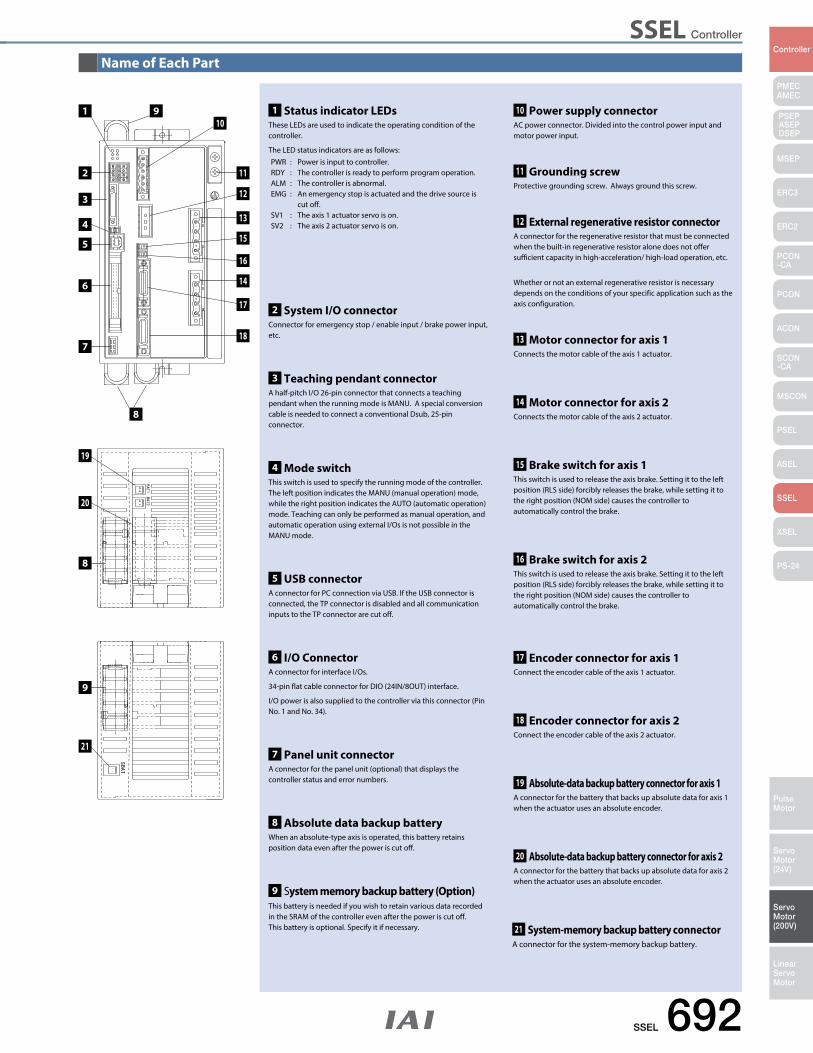
SSEL Controller
SSEL 692
PMECAMEC
Controller
Pulse Motor
Servo Motor (24V)
Servo Motor (200V)
LinearServo Motor
PSEP ASEPDSEP
MSEP
ERC3
ERC2
PCON-CA
PCON
ACON
SCON-CA
MSCON
PSEL
ASEL
SSEL
XSEL
PS-24
Name of Each Part
2 System I/O connectorConnector for emergency stop / enable input / brake power input, etc.
11 Grounding screw Protective grounding screw. Always ground this screw.
12 External regenerative resistor connectorA connector for the regenerative resistor that must be connected when the built-in regenerative resistor alone does not offer sufficient capacity in high-acceleration/ high-load operation, etc.
Whether or not an external regenerative resistor is necessary depends on the conditions of your specific application such as the axis configuration.
13 Motor connector for axis 1 Connects the motor cable of the axis 1 actuator.
14 Motor connector for axis 2 Connects the motor cable of the axis 2 actuator.
16 Brake switch for axis 2 This switch is used to release the axis brake. Setting it to the left position (RLS side) forcibly releases the brake, while setting it to the right position (NOM side) causes the controller to automatically control the brake.
17 Encoder connector for axis 1Connect the encoder cable of the axis 1 actuator.
18 Encoder connector for axis 2Connect the encoder cable of the axis 2 actuator.
19 Absolute-data backup battery connector for axis 1A connector for the battery that backs up absolute data for axis 1 when the actuator uses an absolute encoder.
20 Absolute-data backup battery connector for axis 2A connector for the battery that backs up absolute data for axis 2 when the actuator uses an absolute encoder.
21 System-memory backup battery connectorA connector for the system-memory backup battery.
15 Brake switch for axis 1 This switch is used to release the axis brake. Setting it to the left position (RLS side) forcibly releases the brake, while setting it to the right position (NOM side) causes the controller to automatically control the brake.
3 Teaching pendant connectorA half-pitch I/O 26-pin connector that connects a teaching pendant when the running mode is MANU. A special conversion cable is needed to connect a conventional Dsub, 25-pin connector.
4 Mode switch This switch is used to specify the running mode of the controller. The left position indicates the MANU (manual operation) mode, while the right position indicates the AUTO (automatic operation) mode. Teaching can only be performed as manual operation, and automatic operation using external I/Os is not possible in the MANU mode.
5 USB connectorA connector for PC connection via USB. If the USB connector is connected, the TP connector is disabled and all communication inputs to the TP connector are cut off.
6 I/O Connector A connector for interface I/Os.
34-pin flat cable connector for DIO (24IN/8OUT) interface.
I/O power is also supplied to the controller via this connector (Pin No. 1 and No. 34).
7 Panel unit connector A connector for the panel unit (optional) that displays the controller status and error numbers.
8 Absolute data backup batteryWhen an absolute-type axis is operated, this battery retains position data even after the power is cut off.
9 System memory backup battery (Option)This battery is needed if you wish to retain various data recorded in the SRAM of the controller even after the power is cut off.This battery is optional. Specify it if necessary.
10 Power supply connectorAC power connector. Divided into the control power input and motor power input.
1 Status indicator LEDsThese LEDs are used to indicate the operating condition of the controller.
The LED status indicators are as follows: PWR : Power is input to controller.RDY : The controller is ready to perform program operation. ALM : The controller is abnormal. EMG : An emergency stop is actuated and the drive source is cut off. SV1 : The axis 1 actuator servo is on. SV2 : The axis 2 actuator servo is on.
11
13
14
18
17
12
15
16
1 910
8
2
3
4
5
6
7
19
20
8
9
21
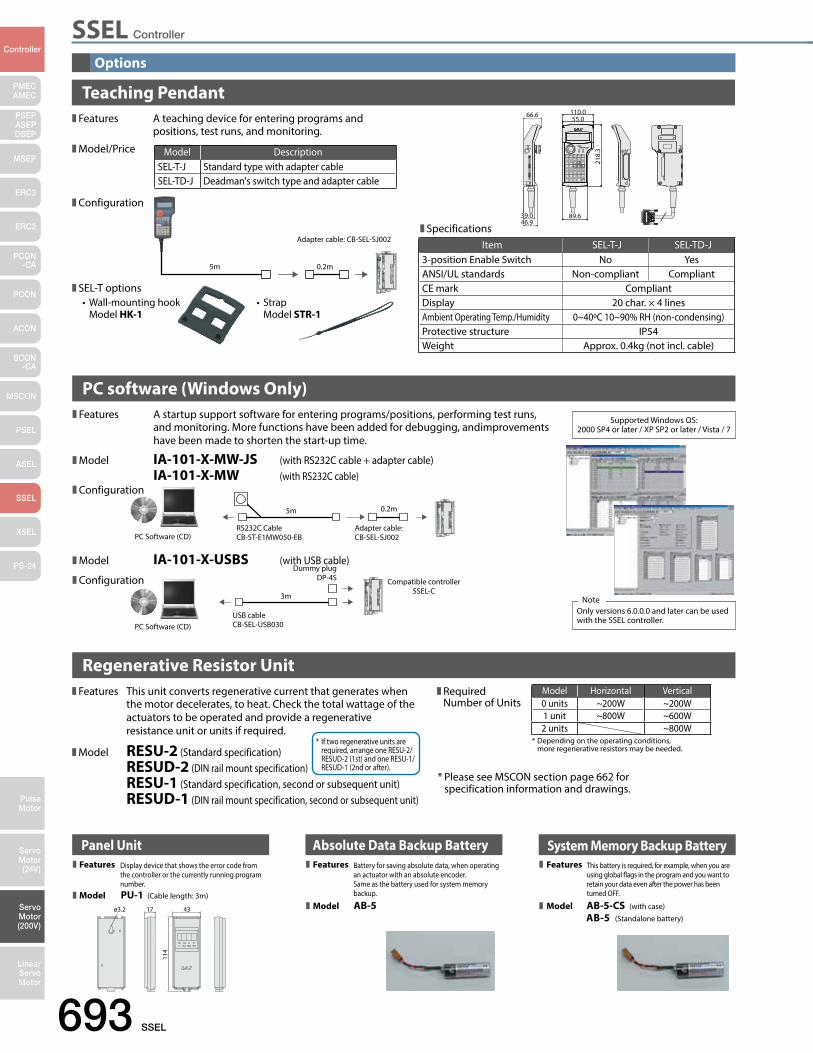
SSEL Controller
693 SSEL
PMECAMEC
Controller
Pulse Motor
Servo Motor (24V)
Servo Motor (200V)
LinearServo Motor
PSEP ASEPDSEP
MSEP
ERC3
ERC2
PCON-CA
PCON
ACON
SCON-CA
MSCON
PSEL
ASEL
SSEL
XSEL
PS-24
Options
Panel UnitDisplay device that shows the error code from the controller or the currently running program number.PU-1 (Cable length: 3m)
ø3.2 17
114
43
Battery for saving absolute data, when operating an actuator with an absolute encoder. Same as the battery used for system memory backup.
AB-5
Absolute Data Backup Battery System Memory Backup BatteryThis battery is required, for example, when you are using global ags in the program and you want to retain your data even after the power has been turned OFF.
AB-5 (Standalone battery)
AB-5-CS (with case)
Features
Model
Features
Model
Features
Model
Teaching Pendant
PC software (Windows Only)Features A startup support software for entering programs/positions, performing test runs, and monitoring. More functions have been added for debugging, andimprovements have been made to shorten the start-up time.
Model IA-101-X-MW-JS (with RS232C cable + adapter cable) IA-101-X-MW (with RS232C cable)Configuration
Model IA-101-X-USBS (with USB cable)
Configuration
RS232C CableCB-ST-E1MW050-EBPC Software (CD)
Adapter cable: CB-SEL-SJ002
0.2m5m
USB cableCB-SEL-USB030PC Software (CD)
Dummy plugDP-4S Compatible controller
SSEL-C3m
Supported Windows OS:2000 SP4 or later / XP SP2 or later / Vista / 7
Only versions 6.0.0.0 and later can be used with the SSEL controller.
Note
Features A teaching device for entering programs and positions, test runs, and monitoring.
Model/Price
Configuration
SEL-T options
66.6
39.039.046.946.9
55.0
89.6
218.
3
110.0
SpecificationsItem SEL-T-J SEL-TD-J
3-position Enable Switch No YesANSI/UL standards Non-compliant CompliantCE mark CompliantDisplay 20 char. × 4 linesAmbient Operating Temp./Humidity 0~40ºC 10~90% RH (non-condensing)Protective structure IP54Weight Approx. 0.4kg (not incl. cable)
Model DescriptionSEL-T-J Standard type with adapter cableSEL-TD-J Deadman's switch type and adapter cable
5m 0.2m
Adapter cable: CB-SEL-SJ002
•Wall-mountinghook Model HK-1
• Strap Model STR-1
Features This unit converts regenerative current that generates when the motor decelerates, to heat. Check the total wattage of the actuators to be operated and provide a regenerative resistance unit or units if required.
Model RESU-2 (Standard specification) RESUD-2 (DIN rail mount specification) RESU-1 (Standard specification, second or subsequent unit) RESUD-1 (DIN rail mount specification, second or subsequent unit)
* If two regenerative units are required, arrange one RESU-2/ RESUD-2 (1st) and one RESU-1/ RESUD-1 (2nd or after).
Regenerative Resistor UnitModel Horizontal Vertical0 units ~200W ~200W1 unit ~800W ~600W2 units ~800W
Required Number of Units
* Please see MSCON section page 662 for specification information and drawings.
* Depending on the operating conditions, more regenerative resistors may be needed.
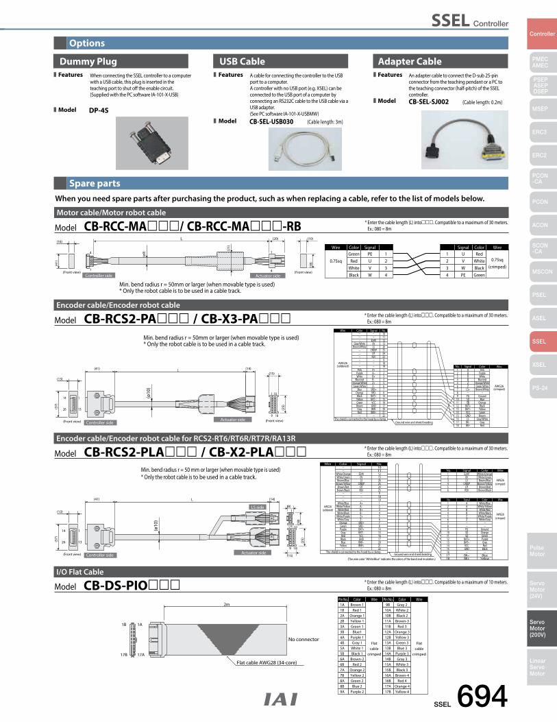
SSEL Controller
SSEL 694
PMECAMEC
Controller
Pulse Motor
Servo Motor (24V)
Servo Motor (200V)
LinearServo Motor
PSEP ASEPDSEP
MSEP
ERC3
ERC2
PCON-CA
PCON
ACON
SCON-CA
MSCON
PSEL
ASEL
SSEL
XSEL
PS-24
Options
Spare parts
ColorPin No. Wire
Flatcable
crimped
Wire
Flatcable
crimped
ColorPin No.1A Brown 1 9B Gray 2
1B 1A
17B 17A
Flat cable AWG28 (34-core)
2m
No connector
1B2A2B3A3B4A4B5A5B6A6B7A7B8A8B9A
Red 1Orange 1Yellow 1Green 1
Blue1Purple 1Gray 1
White 1Black 1
Brown-2Red 2
Orange 2Yellow 2Green 2Blue 2
Purple 2
10A10B11A11B12A12B13A13B14A14B15A15B16A16B17A17B
White 2Black 2
Brown-3Red 3
Orange 3Yellow 3Green 3Blue 3
Purple 3Gray 3
White 3Black 3
Brown-4Red 4
Orange 4Yellow 4
Model CB-DS-PIOI/O Flat Cable
When you need spare parts after purchasing the product, such as when replacing a cable, refer to the list of models below.
Dummy PlugWhen connecting the SSEL controller to a computer with a USB cable, this plug is inserted in the teaching port to shut o the enable circuit. (Supplied with the PC software IA-101-X-USB)
A cable for connecting the controller to the USB port to a computer. A controller with no USB port (e.g. XSEL) can be connected to the USB port of a computer by connecting an RS232C cable to the USB cable via a USB adapter. (See PC software IA-101-X-USBMW)DP-4S
USB Cable Adapter Cable
CB-SEL-USB030 (Cable length: 3m)
An adapter cable to connect the D-sub 25-pin connector from the teaching pendant or a PC to the teaching connector (half-pitch) of the SSEL controller.CB-SEL-SJ002 (Cable length: 0.2m)
Features
Model
Features
Model
Features
Model
* Enter the cable length (L) into. Compatible to a maximum of 10 meters. Ex.: 080 = 8m
* Enter the cable length (L) into. Compatible to a maximum of 30 meters. Ex.: 080 = 8mModel CB-RCS2-PA / CB-X3-PA
Encoder cable/Encoder robot cable
1
9
1
13
14
26
18
10
L
Ground wire and shield braiding GrayRed
Brown
YellowGreen
Black
Green/White AWG26(crimped)
Orange
GroundBlue
Blue/redOrange/White
WhitePurple
Pink
15161718
1413121110
6
987
3
54
21
No.
BK−BK+
GNDLS-
BAT+BAT−VCC
Z
FGSDSD
LS+
B
ZB
AA
Signal Color Wire
The shield is connected to the hood by a clamp.
AWG26(soldered)
Wire
212017
22
6
16151487
3
54
21
25
1819
2324
9
1011121326
No.
BKR+BKR-GND
Z−
BAT+
VCCBAT−
SRD-SRD+
B+
Z+B−
A−A+
CREEPOTRSV
E24V0VLS
Signal
Brown/White
Gray/White
Brown
RedGray
Green/WhiteOrange/White
WhiteBlue/red
Purple
GreenYellowBlack
Blue
Pink
Orange
Color
Brown/WhiteGray/White
(ø10
)
(41) (14)
Controller side
(13)
(37)
Actuator side(Front view) (Front view)
(15)
(25)
Min. bend radius r = 50mm or larger (when movable type is used)* Only the robot cable is to be used in a cable track.
Model CB-RCC-MA/ CB-RCC-MA-RBMotor cable/Motor robot cable
* Enter the cable length (L) into. Compatible to a maximum of 30 meters. Ex.: 080 = 8m
L
Controller side
4
1
1
4
Wire Color Signal
0.75sqGreen PE 1
WireColorSignal
0.75sq(crimped)
RedU1
Actuator side
(10)(20)
(Front view)(Front view)
(16)
(ø9)
(21)
(18)(4
1) RedWhiteBlack
UVW
234
234
VWPE
WhiteBlackGreen
Min. bend radius r = 50mm or larger (when movable type is used)* Only the robot cable is to be used in a cable track.
* Enter the cable length (L) into. Compatible to a maximum of 30 meters. Ex.: 080 = 8mModel CB-RCS2-PLA / CB-X2-PLA
Encoder cable/Encoder robot cable for RCS2-RT6/RT6R/RT7R/RA13R
Ground wire and shield braiding
(crimped)AWG26
AWG26(soldered)
10
White/BlueA1
Wire Color Signal No.
WireColorSignalNo.
The shield is connected to the hood by a clamp.
(The wire color "White/Blue" indicates the colors of the band and insulation.)
(crimped)AWG26
White/OrangeE24V1WireColorSignalNo.
1
9
1
13
14
26
18
10
L
6
1
(ø10
)
Controller side Actuator side
LS side(13)
(41) (14)
(37)
(Front view)
(8)
(15)
(18)
(25)
White/OrangeWhite/GreenBrown/Blue
Brown/YellowBrown/Red
Brown/Black
White/BlueWhite/Yellow
White/RedWhite/Black
White/PurpleWhite/Gray
OrangeGreenPurpleGrayRed
BlackBlue
Yellow
E24V0VLS
CREEPOTRSV
A+A−B+B−Z+Z−
SRD+SRD−BAT+BAT−VCCGNDBKR−BKR+
111213262524239
181912345678
14151617202122
23456
23456789
101112131415161718
0VLS
CREEPOTRSV
ABBZZ
FGSDSD
BAT+BAT−VCCGND
BK−BK+
White/GreenBrown/Blue
Brown/YellowBrown/Red
Brown/Black
White/YellowWhite/Red
White/BlackWhite/PurpleWhite/Gray
GroundOrangeGreenPurpleGrayRed
Black
BlueYellow
Min. bend radius r = 50 mm or larger (when movable type is used)* Only the robot cable is to be used in a cable track.

XSEL Controller
695 XSELL
PMECAMEC
Controller
Pulse Motor
Servo Motor (24V)
Servo Motor (200V)
LinearServo Motor
PSEP ASEPDSEP
MSEP
ERC3
ERC2
PCON-CA
PCON
ACON
SCON-CA
MSCON
PSEL
ASEL
SSEL
XSEL
PS-24
List of Models
Multi-axis program controller for operating RCS2 Series actuators. Up to 8 axes can be simultaneously controlled.
(*1) The maximum output for 1 shaft during vertical operation is limited to 600W.(*2) Preparing for CE compliance
Program controllerFor RCS3 / RCS2 series
Type J K P Q R S
Name Compact Type General Purpose Type Large-Capacity Type
Large-Capacity Type(Global
specification)High-function Type
High-function Type(Global
specification)
External View
DescriptionCompact, low-cost type
ideal for operating low-output actuators
Standard type offering excellent
expandability
Large-capacity type capable of controlling
up to six axes or 2,400W
Large-capacity type conforming to
safety category 4
Up to eight axes can be operated, high-function type
comes with many options
High-function type confirmed to
safety-category 4
Maximum number
of control axes4-axis 6-axis 8-axis
Number of positions 3,000 positions 20,000 positions
Max. 53,332 pisitions(The number vaires according to the number of
controlled axes.)
Total Number of Connectable W 800W (*1) 1600W 2400W 2400W
Power Supply Single-phase AC100V/Single-phase AC200V Single-phase AC200V/3-phase AC200V Single-phase AC200V/3-phase AC200V
Safety Category B B Category 4 compatible B Category 4 compatible
Safety Rating — CE CE (*2) (*2)
Standard Price —
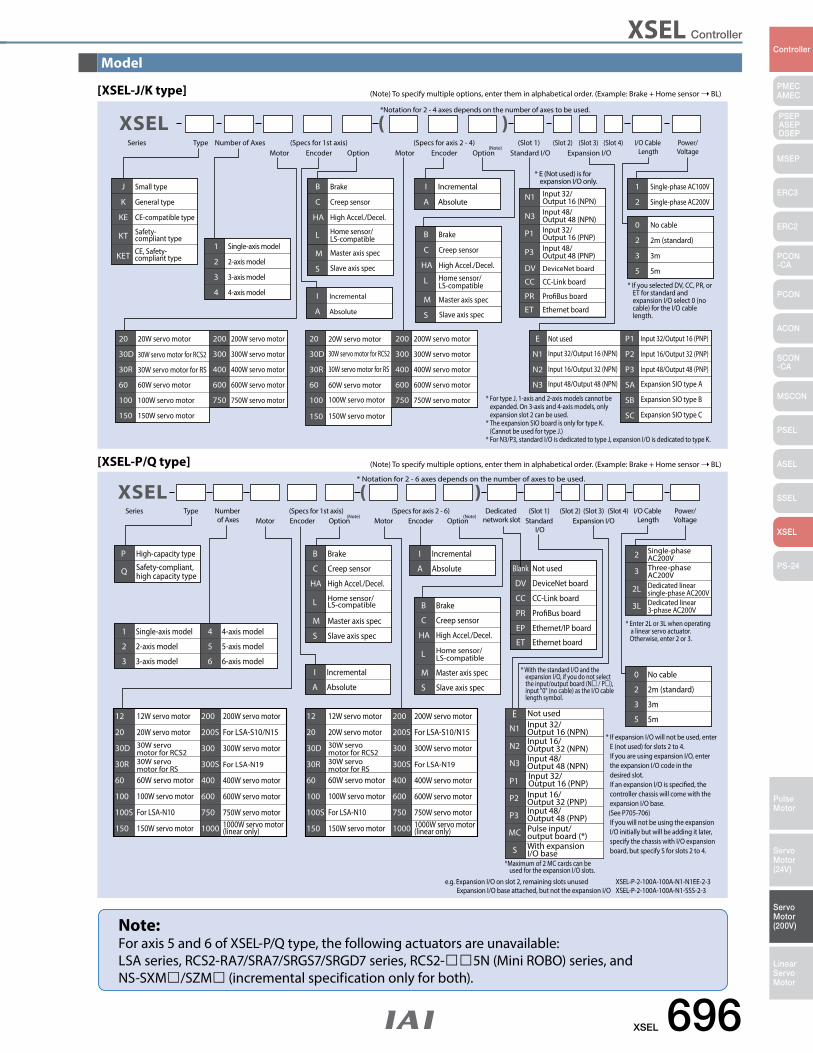
XSEL Controller
XSEL 696
PMECAMEC
Controller
Pulse Motor
Servo Motor (24V)
Servo Motor (200V)
LinearServo Motor
PSEP ASEPDSEP
MSEP
ERC3
ERC2
PCON-CA
PCON
ACON
SCON-CA
MSCON
PSEL
ASEL
SSEL
XSEL
PS-24
Brake
Creep sensor
High Accel./Decel.
Home sensor/LS-compatible
Master axis spec
Slave axis spec
Brake
Creep sensor
High Accel./Decel.
Home sensor/LS-compatible
Master axis spec
Slave axis spec
20W servo motor
30W servo motor for RCS2
30W servo motor for RS
60W servo motor
100W servo motor
150W servo motor
200W servo motor
300W servo motor
400W servo motor
600W servo motor
750W servo motor
20W servo motor
30W servo motor for RCS2
30W servo motor for RS
60W servo motor
100W servo motor
150W servo motor
200W servo motor
300W servo motor
400W servo motor
600W servo motor
750W servo motor
Single-axis model
2-axis model
3-axis model
4-axis model Incremental
Absolute
Incremental
Absolute
Not used
Input 48/Output 48 (NPN)Input 32/Output 16 (PNP)Input 48/Output 48 (PNP)
DeviceNet board
Input 32/Output 16 (NPN)
Input 16/Output 32 (NPN)
Input 48/Output 48 (NPN)
Input 32/Output 16 (PNP)
Input 16/Output 32 (PNP)
Input 48/Output 48 (PNP)
CC-Link board
ProBus board
Ethernet board
Expansion SIO type A
Expansion SIO type B
Expansion SIO type C
Single-phase AC100V
Single-phase AC200V
No cable
2m (standard)
3m
5m
Small type
General type
CE-compatible type
Safety-compliant type
CE, Safety-compliant type
Input 32/Output 16 (NPN)
Series Type Number of AxesMotor Encoder Option Motor Encoder Option
I/O Cable Length
Power/VoltageStandard I/O Expansion I/O
(Slot 1) (Slot 2) (Slot 3) (Slot 4)
B
C
HA
L
M
S
B
C
HA
L
M
S
20
30D
30R
60
100
150
200
300
400
600
750
20
30D
30R
60
100
150
200
300
400
600
750
1
2
3
4 I
A
I
A
E
N3
P1
P3
DV
N1
N2
N3
P1
P2
P3
CC
PR
ET
SA
SB
SC
1
2
0
2
3
5
J
K
KE
KT
KET
(Specs for 1st axis) (Specs for axis 2 - 4)
*Notation for 2 - 4 axes depends on the number of axes to be used.
N1
* For type J, 1-axis and 2-axis models cannot be expanded. On 3-axis and 4-axis models, only expansion slot 2 can be used.* The expansion SIO board is only for type K. (Cannot be used for type J.)* For N3/P3, standard I/O is dedicated to type J, expansion I/O is dedicated to type K.
* If you selected DV, CC, PR, or ET for standard and expansion I/O select 0 (no cable) for the I/O cable length.
* E (Not used) is for expansion I/O only.
(Note)
[XSEL-J/K type]
Series Type Number of Axes Motor Encoder Option Motor Encoder Option
I/O Cable Length
Power/VoltageStandard
I/OExpansion I/O
(Slot 1) (Slot 2) (Slot 3) (Slot 4)
Blank Not used
DV DeviceNet board
CC CC-Link board
PR ProBus board
EP Ethernet/IP board
ET Ethernet board1 Single-axis model
2 2-axis model
3 3-axis model
4 4-axis model
5 5-axis model
6 6-axis modelI Incremental
A Absolute
I Incremental
A Absolute
E Not used
N2 Input 16/Output 32 (NPN)
N3 Input 48/Output 48 (NPN)
P1 Input 32/Output 16 (PNP)
P2 Input 16/Output 32 (PNP)
P3 Input 48/Output 48 (PNP)
MC Pulse input/output board (*)
S With expansion I/O base
2 Single-phase AC200V
3 Three-phase AC200V
2L Dedicated linear single-phase AC200V
3L Dedicated linear 3-phase AC200V
0 No cable
2 2m (standard)
3 3m
5 5m
P High-capacity type
Q Safety-compliant, high capacity type
(Specs for 1st axis) (Specs for axis 2 - 6) Dedicated network slot
* Notation for 2 - 6 axes depends on the number of axes to be used.
B Brake
C Creep sensor
HA High Accel./Decel.
L Home sensor/LS-compatible
M Master axis spec
S Slave axis spec
B Brake
C Creep sensor
HA High Accel./Decel.
L Home sensor/LS-compatible
M Master axis spec
S Slave axis spec
* If expansion I/O will not be used, enter E (not used) for slots 2 to 4. If you are using expansion I/O, enter the expansion I/O code in the desired slot. If an expansion I/O is specied, the controller chassis will come with the expansion I/O base. (See P705-706) If you will not be using the expansion I/O initially but will be adding it later, specify the chassis with I/O expansion board, but specify S for slots 2 to 4.
* Enter 2L or 3L when operating a linear servo actuator.
Otherwise, enter 2 or 3.
e.g. Expansion I/O on slot 2, remaining slots unused XSEL-P-2-100A-100A-N1-N1EE-2-3Expansion I/O base attached, but not the expansion I/O XSEL-P-2-100A-100A-N1-SSS-2-3
(Note) (Note)
* With the standard I/O and the expansion I/O, if you do not select the input/output board (N / P), input "0" (no cable) as the I/O cable length symbol.
*Maximum of 2 MC cards can be used for the expansion I/O slots.
N1 Input 32/Output 16 (NPN)
12
20
30D
30R
60
100
100S
150
12W servo motor
20W servo motor30W servo motor for RCS230W servo motor for RS60W servo motor
100W servo motor
For LSA-N10
150W servo motor
200
200S
300
300S
400
600
750
1000
200W servo motor
For LSA-S10/N15
300W servo motor
For LSA-N19
400W servo motor
600W servo motor
750W servo motor1000W servo motor (linear only)
(Note) To specify multiple options, enter them in alphabetical order. (Example: Brake + Home sensor BL)
[XSEL-P/Q type] (Note) To specify multiple options, enter them in alphabetical order. (Example: Brake + Home sensor BL)
Note:For axis 5 and 6 of XSEL-P/Q type, the following actuators are unavailable:LSA series, RCS2-RA7/SRA7/SRGS7/SRGD7 series, RCS2-5N (Mini ROBO) series, and NS-SXM/SZM (incremental specification only for both).
Model
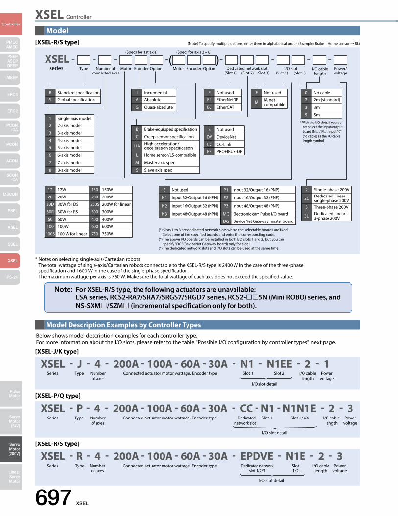
XSEL Controller
697 XSEL
PMECAMEC
Controller
Pulse Motor
Servo Motor (24V)
Servo Motor (200V)
LinearServo Motor
PSEP ASEPDSEP
MSEP
ERC3
ERC2
PCON-CA
PCON
ACON
SCON-CA
MSCON
PSEL
ASEL
SSEL
XSEL
PS-24
Model
Model Description Examples by Controller Types
[XSEL-J/K type]
XSEL - J - 4 - 200A - 100A - 60A - 30A - N1 - N1EE - 2 - 1Series Type Number
of axesSlot 1 Slot 2
I/O slot detail
I/O cable length
Connected actuator motor wattage, Encoder type Power voltage
Below shows model description examples for each controller type.For more information about the I/O slots, please refer to the table "Possible I/O configuration by controller types" next page.
[XSEL-P/Q type]
XSEL - P - 4 - 200A - 100A - 60A - 30A - CC - N1 - N1N1E - 2 - 3Series Type Number
of axesDedicated
network slot 1Slot 1 Slot 2/3/4
I/O slot detail
I/O cable length
Connected actuator motor wattage, Encoder type Power voltage
[XSEL-R/S type]
I/O slot detail
XSEL - R - 4 - 200A - 100A - 60A - 30A - EPDVE - N1E - 2 - 3Series Type Number
of axesDedicated network
slot 1/2/3Slot 1/2
I/O cable length
Connected actuator motor wattage, Encoder type Power voltage
* Notes on selecting single-axis/Cartesian robots The total wattage of single-axis/Cartesian robots connectable to the XSEL-R/S type is 2400 W in the case of the three-phase specification and 1600 W in the case of the single-phase specification. The maximum wattage per axis is 750 W. Make sure the total wattage of each axis does not exceed the specified value.
Note: For XSEL-R/S type, the following actuators are unavailable: LSA series, RCS2-RA7/SRA7/SRGS7/SRGD7 series, RCS2-5N (Mini ROBO) series, and NS-SXM/SZM (incremental specification only for both).
[XSEL-R/S type] (Note) To specify multiple options, enter them in alphabetical order. (Example: Brake + Home sensor BL)
(Specs for 1st axis) (Specs for axis 2 – 8)
XSEL - - - -( )- - - - series Type Number of
connected axesDedicated network slot
(Slot 1) (Slot 2) (Slot 3)I/O slot
(Slot 1) (Slot 2)I/O cable
lengthMotor Power/
voltageEncoder Option Motor Encoder Option
(*) Slots 1 to 3 are dedicated network slots where the selectable boards are fixed. Select one of the specified boards and enter the corresponding code. (*) The above I/O boards can be installed in both I/O slots 1 and 2, but you can specify “DG” (DeviceNet Gateway board) only for slot 1. (*) The dedicated network slots and I/O slots can be used at the same time.
1 Single-axis model
2 2-axis model
3 3-axis model
4 4-axis model
5 5-axis model
6 6-axis model
7 7-axis model
8 8-axis model
R Standard specification
S Global specification
0 No cable
2 2m (standard)
3 3m
5 5m
2 Single-phase 200V
2L Dedicated linear single-phase 200V
3 Three-phase 200V
3L Dedicated linear 3-phase 200V
12 12W 150 150W
20 20W 200 200W
30D 30W for DS 200S 200W for linear
30R 30W for RS 300 300W
60 60W 400 400W
100 100W 600 600W
100S 100 W for linear 750 750W
E Not used P1 Input 32/Output 16 (PNP)
N1 Input 32/Output 16 (NPN) P2 Input 16/Output 32 (PNP)
N2 Input 16/Output 32 (NPN) P3 Input 48/Output 48 (PNP)
N3 Input 48/Output 48 (NPN) MC Electronic cam Pulse I/O board
DG DeviceNet Gateway master board
I Incremental
A Absolute
G Quasi-absolute
E Not used
EP EtherNet/IP
EC EtherCAT
B Brake-equipped specification
C Creep sensor specification
HA High acceleration/deceleration specification
L Home sensor/LS-compatible
M Master axis spec
S Slave axis spec
E Not used
IA IA net- compatible
E Not used
DV DeviceNet
CC CC-Link
PR PROFIBUS-DP
* With the I/O slots, if you do not select the input/output board (N / P), input "0" (no cable) as the I/O cable length symbol.
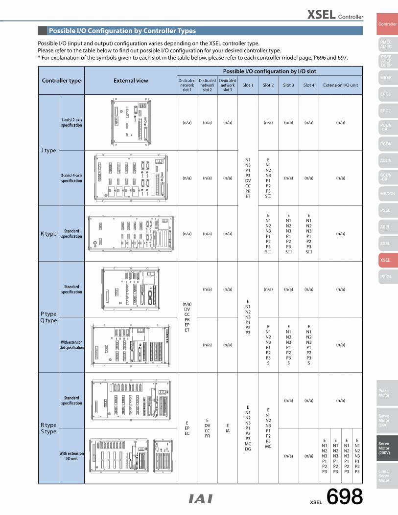
XSEL Controller
XSEL 698
PMECAMEC
Controller
Pulse Motor
Servo Motor (24V)
Servo Motor (200V)
LinearServo Motor
PSEP ASEPDSEP
MSEP
ERC3
ERC2
PCON-CA
PCON
ACON
SCON-CA
MSCON
PSEL
ASEL
SSEL
XSEL
PS-24
Possible I/O Configuration by Controller Types
Possible I/O (input and output) configuration varies depending on the XSEL controller type.Please refer to the table below to find out possible I/O configuration for your desired controller type.* For explanation of the symbols given to each slot in the table below, please refer to each controller model page, P696 and 697.
Controller type External view
Possible I/O configuration by I/O slotDedicated network
slot 1
Dedicated network
slot 2
Dedicated network
slot 3Slot 1 Slot 2 Slot 3 Slot 4 Extension I/O unit
J type
1-axis/ 2-axisspecification (n/a) (n/a) (n/a)
N1N3P1P3DVCCPRET
(n/a) (n/a) (n/a) (n/a)
3-axis/ 4-axisspecification (n/a) (n/a) (n/a)
EN1N2N3P1P2P3S
(n/a) (n/a) (n/a)
K type Standardspecification (n/a) (n/a) (n/a)
EN1N2N3P1P2P3S
EN1N2N3P1P2P3S
EN1N2N3P1P2P3S
(n/a)
P typeQ type
Standardspecification
(n/a)DVCCPREPET
(n/a) (n/a)
EN1N2N3P1P2P3
(n/a) (n/a) (n/a) (n/a)
With extension slot specification (n/a) (n/a)
EN1N2N3P1P2P3S
EN1N2N3P1P2P3S
EN1N2N3P1P2P3S
(n/a)
R typeS type
Standardspecification
EEPEC
EDVCCPR
EIA
EN1N2N3P1P2P3MCDG
EN1N2N3P1P2P3MC
(n/a) (n/a) (n/a)
With extension I/O unit (n/a) (n/a)
EN1N2N3P1P2P3
EN1N2N3P1P2P3
EN1N2N3P1P2P3
EN1N2N3P1P2P3
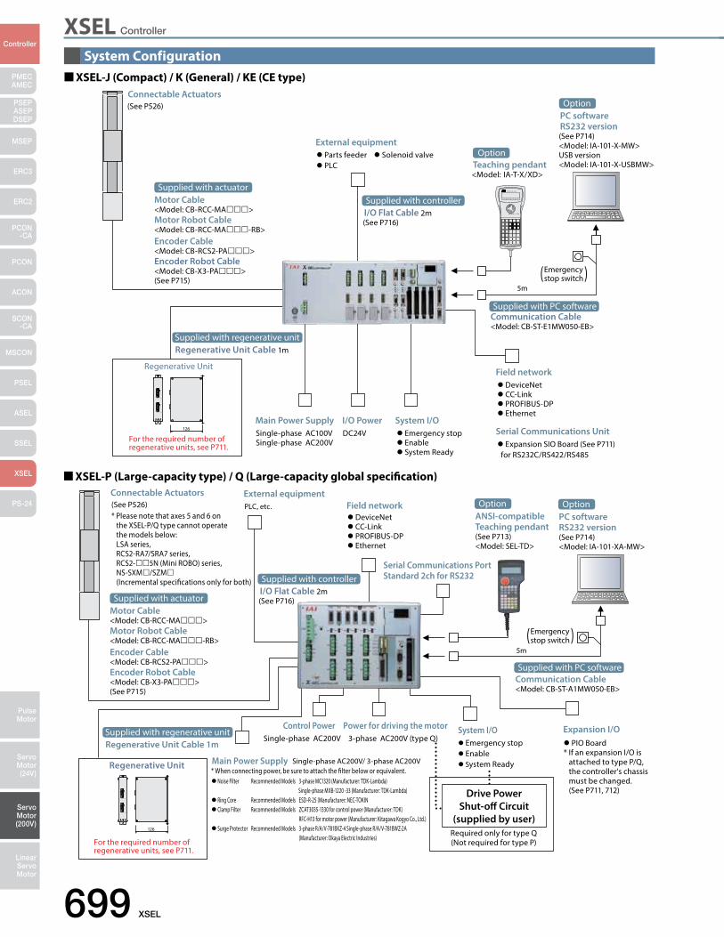
XSEL Controller
699 XSEL
PMECAMEC
Controller
Pulse Motor
Servo Motor (24V)
Servo Motor (200V)
LinearServo Motor
PSEP ASEPDSEP
MSEP
ERC3
ERC2
PCON-CA
PCON
ACON
SCON-CA
MSCON
PSEL
ASEL
SSEL
XSEL
PS-24
(See P526)Connectable Actuators
Parts feeder Solenoid valve PLC
External equipment
Single-phase AC100VSingle-phase AC200V
Main Power SupplyDC24VI/O Power
Emergency stop Enable System Ready
System I/O
DeviceNet CC-Link PROFIBUS-DP Ethernet
Expansion SIO Board (See P711) for RS232C/RS422/RS485
Field network
Serial Communications Unit
XSEL-J (Compact) / K (General) / KE (CE type)
5m
Motor Cable<Model: CB-RCC-MA>Motor Robot Cable<Model: CB-RCC-MA-RB>Encoder Cable<Model: CB-RCS2-PA>Encoder Robot Cable<Model: CB-X3-PA>(See P715)
Supplied with actuator
Emergency stop switch
Teaching pendant<Model: IA-T-X/XD>
Option
PC softwareRS232 version(See P714)<Model: IA-101-X-MW>USB version<Model: IA-101-X-USBMW>
Option
Communication Cable<Model: CB-ST-E1MW050-EB>
Supplied with PC software
I/O Flat Cable 2m(See P716)
Supplied with controller
Regenerative Unit Cable 1mSupplied with regenerative unit
Regenerative Unit
For the required number ofregenerative units, see P711.
RB+
RB−
RB OUT
RB+
RB−
RB IN
126
(See P526)* Please note that axes 5 and 6 on the XSEL-P/Q type cannot operate the models below: LSA series, RCS2-RA7/SRA7 series, RCS2-5N (Mini ROBO) series, NS-SXM/SZM (Incremental specications only for both)
Connectable ActuatorsPLC, etc.
External equipment
DeviceNet CC-Link PROFIBUS-DP Ethernet
Field network
Serial Communications PortStandard 2ch for RS232
PIO Board* If an expansion I/O is attached to type P/Q, the controller's chassis must be changed. (See P711, 712)
Expansion I/O
Required only for type Q(Not required for type P)
Single-phase AC200VControl Power
* When connecting power, be sure to attach the lter below or equivalent.Single-phase AC200V/ 3-phase AC200VMain Power Supply
Noise Filter Recommended Models 3-phase MC1320 (Manufacturer: TDK-Lambda) Single-phase MXB-1220 -33 (Manufacturer: TDK-Lambda) Ring Core Recommended Models ESD-R-25 (Manufacturer: NEC-TOKIN Clamp Filter Recommended Models ZCAT3035-1330 for control power (Manufacturer: TDK) RFC-H13 for motor power (Manufacturer: Kitagawa Kogyo Co., Ltd.) Surge Protector Recommended Models 3-phase R/A/V-781BXZ-4 Single-phase R/A/V-781BWZ-2A (Manufacturer: Okaya Electric Industries)
3-phase AC200V (type Q)Power for driving the motor
Emergency stop Enable System Ready
System I/O
5m
Emergency stop switch
Motor Cable<Model: CB-RCC-MA>Motor Robot Cable<Model: CB-RCC-MA-RB>Encoder Cable<Model: CB-RCS2-PA>Encoder Robot Cable<Model: CB-X3-PA>(See P715)
Supplied with actuator
Drive PowerShut-o Circuit
(supplied by user)
ANSI-compatibleTeaching pendant(See P713)<Model: SEL-TD>
OptionPC softwareRS232 version(See P714)<Model: IA-101-XA-MW>
Option
Supplied with PC softwareCommunication Cable<Model: CB-ST-A1MW050-EB>
Regenerative Unit
For the required number ofregenerative units, see P711.
I/O Flat Cable 2m(See P716)
Supplied with controller
Regenerative Unit Cable 1mSupplied with regenerative unit
RB+
RB−
RB OUT
RB+
RB−
RB IN
126
XSEL-P (Large-capacity type) / Q (Large-capacity global specication)
System Configuration
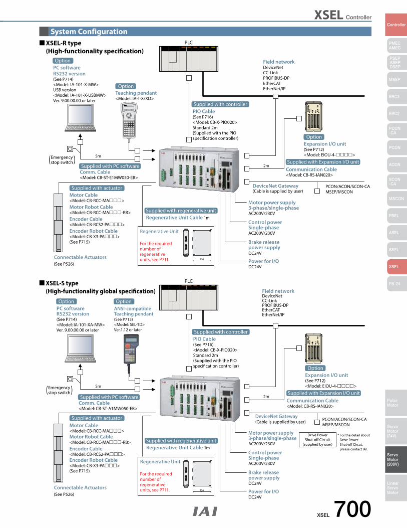
XSEL Controller
XSEL 700
PMECAMEC
Controller
Pulse Motor
Servo Motor (24V)
Servo Motor (200V)
LinearServo Motor
PSEP ASEPDSEP
MSEP
ERC3
ERC2
PCON-CA
PCON
ACON
SCON-CA
MSCON
PSEL
ASEL
SSEL
XSEL
PS-24
System ConfigurationPLC
Field networkDeviceNetCC-LinkPROFIBUS-DPEtherCATEtherNet/IP
5m
2m
2m
Brake releasepower supplyDC24V
Power for I/ODC24V
Control powerSingle-phaseAC200V/230V
Motor power supply3-phase/single-phaseAC200V/230V
Teaching pendant<Model: IA-T-X/XD>
Option
OptionExpansion I/O unit(See P712)<Model: EIOU-4->
PLC
Field networkDeviceNetCC-LinkPROFIBUS-DPEtherCATEtherNet/IP
XSEL-S type (High-functionality global specication)
Drive PowerShut-o Circuit
(supplied by user)
DeviceNet Gateway(Cable is supplied by user)
DeviceNet Gateway(Cable is supplied by user)
* For the detail about Drive Power Shut-off Circut, please contact IAI.
5m
PCON/ACON/SCON-CAMSEP/MSCON
(See P526)Connectable Actuators
Brake releasepower supplyDC24V
Power for I/ODC24V
Control powerSingle-phaseAC200V/230V
Motor power supply3-phase/single-phaseAC200V/230V
(See P526)Connectable Actuators
Emergency stop switch
PIO Cable(See P716)<Model: CB-X-PIO020>Standard 2m(Supplied with the PIO specication controller)
Supplied with controller
Motor Cable<Model: CB-RCC-MA>Motor Robot Cable<Model: CB-RCC-MA-RB>Encoder Cable<Model: CB-RCS2-PA>Encoder Robot Cable<Model: CB-X3-PA>(See P715)
Supplied with actuator
Communication Cable<Model: CB-RS-IAN020>
Supplied with Expansion I/O unit
PCON/ACON/SCON-CAMSEP/MSCON
Comm. Cable<Model: CB-ST-E1MW050-EB>
Supplied with PC software
PC softwareRS232 version(See P714)<Model: IA-101-XA-MW>Ver. 9.00.00.00 or later
OptionANSI-compatibleTeaching pendant(See P713)<Model: SEL-TD>Ver.1.12 or later
Option
Emergency stop switch
Comm. Cable<Model: CB-ST-A1MW050-EB>
Supplied with PC software
PIO Cable(See P716)<Model: CB-X-PIO020>Standard 2m(Supplied with the PIO specication controller)
Supplied with controller
Motor Cable<Model: CB-RCC-MA>Motor Robot Cable<Model: CB-RCC-MA-RB>Encoder Cable<Model: CB-RCS2-PA>Encoder Robot Cable<Model: CB-X3-PA>(See P715)
Supplied with actuator
OptionExpansion I/O unit(See P712)<Model: EIOU-4->
Communication Cable<Model: CB-RS-IAN020>
Supplied with Expansion I/O unit
PC softwareRS232 version(See P714)<Model: IA-101-X-MW>USB version<Model: IA-101-X-USBMW>Ver. 9.00.00.00 or later
Option
XSEL-R type (High-functionality specication)
Regenerative Unit Cable 1mSupplied with regenerative unit
Regenerative Unit
For the required number ofregenerative units, see P711.
Regenerative Unit Cable 1mSupplied with regenerative unit
RB+
RB−
RB OUT
RB+
RB−
RB IN
126
RB+
RB−
RB OUT
RB+
RB−
RB IN
126
Regenerative Unit
For the required number ofregenerative units, see P711.
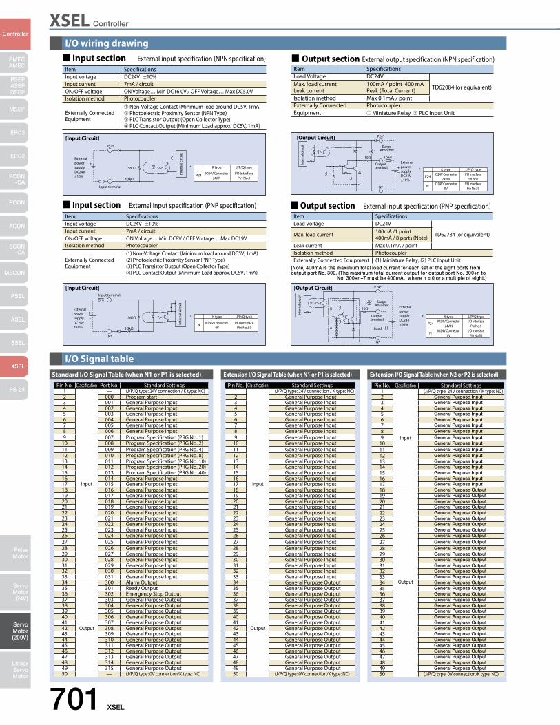
XSEL Controller
701 XSEL
PMECAMEC
Controller
Pulse Motor
Servo Motor (24V)
Servo Motor (200V)
LinearServo Motor
PSEP ASEPDSEP
MSEP
ERC3
ERC2
PCON-CA
PCON
ACON
SCON-CA
MSCON
PSEL
ASEL
SSEL
XSEL
PS-24
I/O wiring drawing
I/O Signal table
[Input Circuit]
560Ω
3.3kΩ
N*
Input terminal
External power supply DC24V±10%
K type
IO24V Connector 0V
I/O InterfacePin No.50
J/P/Q type
N
*
Inte
rnal
circ
uit
[Output Circuit]
+−
10Ω
P24*
External power supply DC24V±10%
N*
Output terminal
Load
Surge Absorber
K typeIO24V Connector
24VINI/O Interface
Pin No.1
J/P/Q type
P24
IO24V Connector0V
I/O InterfacePin No.50
N
*
Inte
rnal
circ
uit
[Input Circuit]
560Ω
3.3kΩ
Input terminal
P24*
+−
External power supply DC24V±10%
K type
IO24V Connector24VIN
I/O InterfacePin No.1
J/P/Q type
P24
*
Inte
rnal
circ
uit
[Output Circuit]
10Ω
P24*
D
Output terminal
Load
Surge Absorber
K typeIO24V Connector
24VINI/O Interface
Pin No.1
J/P/Q type
P24
IO24V Connector0V
I/O InterfacePin No.50
N
*
N*
External power supply DC24V±10%
Inte
rnal
circ
uit
Item SpecificationsInput voltage DC24V ±10%Input current 7mA / circuitON/OFF voltage ON Voltage… Min DC16.0V / OFF Voltage… Max DC5.0VIsolation method Photocoupler
Externally Connected Equipment
➀ Non-Voltage Contact (Minimum load around DC5V, 1mA)➁ Photoelectric Proximity Sensor (NPN Type)➂ PLC Transistor Output (Open Collector Type)➃ PLC Contact Output (Minimum Load approx. DC5V, 1mA)
Item SpecificationsLoad Voltage DC24V
TD62084 (or equivalent)Max. load current Leak current
100mA / point 400 mAPeak (Total Current)
Isolation method Max 0.1mA / pointExternally Connected PhotocouplerEquipment ➀ Miniature Relay, ➁ PLC Input Unit
Item SpecificationsLoad Voltage DC24V
TD62784 (or equivalent)Max. load current 100mA /1 point 400mA / 8 ports (Note)
Leak current Max 0.1mA / pointIsolation method PhotocouplerExternally Connected Equipment (1) Miniature Relay, (2) PLC Input Unit
Item SpecificationsInput voltage DC24V ±10%Input current 7mA / circuitON/OFF voltage ON Voltage… Min DC8V / OFF Voltage… Max DC19VIsolation method Photocoupler
Externally Connected Equipment
(1) Non-Voltage Contact (Minimum load around DC5V, 1mA)(2) Photoelectric Proximity Sensor (PNP Type)(3) PLC Transistor Output (Open Collector Type)(4) PLC Contact Output (Minimum Load approx. DC5V, 1mA)
Standard I/O Signal Table (when N1 or P1 is selected)
Pin No. Classification Port No. Standard Settings1
Input
— (J/P/Q type: 24V connection / K type: NC)2 000 Program start3 001 General Purpose Input4 002 General Purpose Input5 003 General Purpose Input6 004 General Purpose Input7 005 General Purpose Input8 006 General Purpose Input9 007 Program Specification (PRG No. 1)
10 008 Program Specification (PRG No. 2)11 009 Program Specification (PRG No. 4)12 010 Program Specification (PRG No. 8)13 011 Program Specification (PRG No. 10)14 012 Program Specification (PRG No. 20)15 013 Program Specification (PRG No. 40)16 014 General Purpose Input17 015 General Purpose Input18 016 General Purpose Input19 017 General Purpose Input20 018 General Purpose Input21 019 General Purpose Input22 020 General Purpose Input23 021 General Purpose Input24 022 General Purpose Input25 023 General Purpose Input26 024 General Purpose Input27 025 General Purpose Input28 026 General Purpose Input29 027 General Purpose Input30 028 General Purpose Input31 029 General Purpose Input32 030 General Purpose Input33 031 General Purpose Input34
Output
300 Alarm Output35 301 Ready Output36 302 Emergency Stop Output37 303 General Purpose Output38 304 General Purpose Output39 305 General Purpose Output40 306 General Purpose Output41 307 General Purpose Output42 308 General Purpose Output43 309 General Purpose Output44 310 General Purpose Output45 311 General Purpose Output46 312 General Purpose Output47 313 General Purpose Output48 314 General Purpose Output49 315 General Purpose Output50 — (J/P/Q type: 0V connection/K type: NC)
Extension I/O Signal Table (when N1 or P1 is selected)
Pin No. Classification Standard Settings1
Input
(J/P/Q type: 24V connection / K type: NC)2 General Purpose Input3 General Purpose Input4 General Purpose Input5 General Purpose Input6 General Purpose Input7 General Purpose Input8 General Purpose Input9 General Purpose Input
10 General Purpose Input11 General Purpose Input12 General Purpose Input13 General Purpose Input14 General Purpose Input15 General Purpose Input16 General Purpose Input17 General Purpose Input18 General Purpose Input19 General Purpose Input20 General Purpose Input21 General Purpose Input22 General Purpose Input23 General Purpose Input24 General Purpose Input25 General Purpose Input26 General Purpose Input27 General Purpose Input28 General Purpose Input29 General Purpose Input30 General Purpose Input31 General Purpose Input32 General Purpose Input33 General Purpose Input34
Output
General Purpose Output35 General Purpose Output36 General Purpose Output37 General Purpose Output38 General Purpose Output39 General Purpose Output40 General Purpose Output41 General Purpose Output42 General Purpose Output43 General Purpose Output44 General Purpose Output45 General Purpose Output46 General Purpose Output47 General Purpose Output48 General Purpose Output49 General Purpose Output50 (J/P/Q type: 0V connection/K type: NC)
Extension I/O Signal Table (when N2 or P2 is selected)
Pin No. Classification Standard Settings1
Input
(J/P/Q type: 24V connection / K type: NC)2 General Purpose Input3 General Purpose Input4 General Purpose Input5 General Purpose Input6 General Purpose Input7 General Purpose Input8 General Purpose Input9 General Purpose Input
10 General Purpose Input11 General Purpose Input12 General Purpose Input13 General Purpose Input14 General Purpose Input15 General Purpose Input16 General Purpose Input17 General Purpose Input18
Output
General Purpose Output19 General Purpose Output20 General Purpose Output21 General Purpose Output22 General Purpose Output23 General Purpose Output24 General Purpose Output25 General Purpose Output26 General Purpose Output27 General Purpose Output28 General Purpose Output29 General Purpose Output30 General Purpose Output31 General Purpose Output32 General Purpose Output33 General Purpose Output34 General Purpose Output35 General Purpose Output36 General Purpose Output37 General Purpose Output38 General Purpose Output39 General Purpose Output40 General Purpose Output41 General Purpose Output42 General Purpose Output43 General Purpose Output44 General Purpose Output45 General Purpose Output46 General Purpose Output47 General Purpose Output48 General Purpose Output49 General Purpose Output50 (J/P/Q type: 0V connection/K type: NC)
Input sectionExternal input specification (NPN specification)
Input section External input specification (PNP specification) Output section External input specification (PNP specification)
Output sectionExternal output specification (NPN specification)
(Note) 400mA is the maximum total load current for each set of the eight ports from output port No. 300. (The maximum total current output for output port No. 300+n to
No. 300+n+7 must be 400mA, where n = 0 or a multiple of eight.)
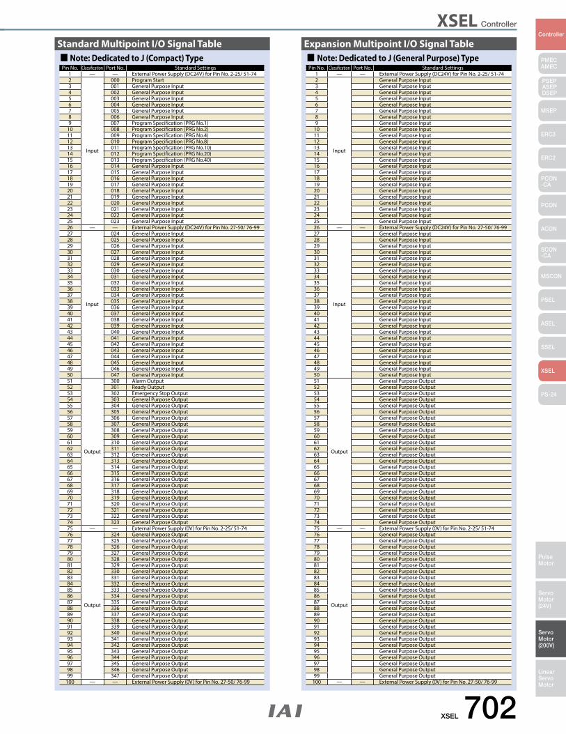
XSEL Controller
XSEL 702
PMECAMEC
Controller
Pulse Motor
Servo Motor (24V)
Servo Motor (200V)
LinearServo Motor
PSEP ASEPDSEP
MSEP
ERC3
ERC2
PCON-CA
PCON
ACON
SCON-CA
MSCON
PSEL
ASEL
SSEL
XSEL
PS-24
Pin No. Classification Port No. Standard Settings1 — — External Power Supply (DC24V) for Pin No. 2-25/ 51-742
Input
000 Program Start3 001 General Purpose Input4 002 General Purpose Input5 003 General Purpose Input6 004 General Purpose Input7 005 General Purpose Input8 006 General Purpose Input9 007 Program Specification (PRG No.1)
10 008 Program Specification (PRG No.2)11 009 Program Specification (PRG No.4)12 010 Program Specification (PRG No.8)13 011 Program Specification (PRG No.10)14 012 Program Specification (PRG No.20)15 013 Program Specification (PRG No.40)16 014 General Purpose Input17 015 General Purpose Input18 016 General Purpose Input19 017 General Purpose Input20 018 General Purpose Input21 019 General Purpose Input22 020 General Purpose Input23 021 General Purpose Input24 022 General Purpose Input25 023 General Purpose Input26 — — External Power Supply (DC24V) for Pin No. 27-50/ 76-9927
Input
024 General Purpose Input28 025 General Purpose Input29 026 General Purpose Input30 027 General Purpose Input31 028 General Purpose Input32 029 General Purpose Input33 030 General Purpose Input34 031 General Purpose Input35 032 General Purpose Input36 033 General Purpose Input37 034 General Purpose Input38 035 General Purpose Input39 036 General Purpose Input40 037 General Purpose Input41 038 General Purpose Input42 039 General Purpose Input43 040 General Purpose Input44 041 General Purpose Input45 042 General Purpose Input46 043 General Purpose Input47 044 General Purpose Input48 045 General Purpose Input49 046 General Purpose Input50 047 General Purpose Input51
Output
300 Alarm Output52 301 Ready Output53 302 Emergency Stop Output54 303 General Purpose Output55 304 General Purpose Output56 305 General Purpose Output57 306 General Purpose Output58 307 General Purpose Output59 308 General Purpose Output60 309 General Purpose Output61 310 General Purpose Output62 311 General Purpose Output63 312 General Purpose Output64 313 General Purpose Output65 314 General Purpose Output66 315 General Purpose Output67 316 General Purpose Output68 317 General Purpose Output69 318 General Purpose Output70 319 General Purpose Output71 320 General Purpose Output72 321 General Purpose Output73 322 General Purpose Output74 323 General Purpose Output75 — — External Power Supply (0V) for Pin No. 2-25/ 51-7476
Output
324 General Purpose Output77 325 General Purpose Output78 326 General Purpose Output79 327 General Purpose Output80 328 General Purpose Output81 329 General Purpose Output82 330 General Purpose Output83 331 General Purpose Output84 332 General Purpose Output85 333 General Purpose Output86 334 General Purpose Output87 335 General Purpose Output88 336 General Purpose Output89 337 General Purpose Output90 338 General Purpose Output91 339 General Purpose Output92 340 General Purpose Output93 341 General Purpose Output94 342 General Purpose Output95 343 General Purpose Output96 344 General Purpose Output97 345 General Purpose Output98 346 General Purpose Output99 347 General Purpose Output
100 — — External Power Supply (0V) for Pin No. 27-50/ 76-99
Note: Dedicated to J (Compact) TypeStandard Multipoint I/O Signal Table
Pin No. Classification Port No. Standard Settings1 — — External Power Supply (DC24V) for Pin No. 2-25/ 51-742
Input
General Purpose Input3 General Purpose Input4 General Purpose Input5 General Purpose Input6 General Purpose Input7 General Purpose Input8 General Purpose Input9 General Purpose Input
10 General Purpose Input11 General Purpose Input12 General Purpose Input13 General Purpose Input14 General Purpose Input15 General Purpose Input16 General Purpose Input17 General Purpose Input18 General Purpose Input19 General Purpose Input20 General Purpose Input21 General Purpose Input22 General Purpose Input23 General Purpose Input24 General Purpose Input25 General Purpose Input26 — — External Power Supply (DC24V) for Pin No. 27-50/ 76-9927
Input
General Purpose Input28 General Purpose Input29 General Purpose Input30 General Purpose Input31 General Purpose Input32 General Purpose Input33 General Purpose Input34 General Purpose Input35 General Purpose Input36 General Purpose Input37 General Purpose Input38 General Purpose Input39 General Purpose Input40 General Purpose Input41 General Purpose Input42 General Purpose Input43 General Purpose Input44 General Purpose Input45 General Purpose Input46 General Purpose Input47 General Purpose Input48 General Purpose Input49 General Purpose Input50 General Purpose Input51
Output
General Purpose Output52 General Purpose Output53 General Purpose Output54 General Purpose Output55 General Purpose Output56 General Purpose Output57 General Purpose Output58 General Purpose Output59 General Purpose Output60 General Purpose Output61 General Purpose Output62 General Purpose Output63 General Purpose Output64 General Purpose Output65 General Purpose Output66 General Purpose Output67 General Purpose Output68 General Purpose Output69 General Purpose Output70 General Purpose Output71 General Purpose Output72 General Purpose Output73 General Purpose Output74 General Purpose Output75 — — External Power Supply (0V) for Pin No. 2-25/ 51-7476
Output
General Purpose Output77 General Purpose Output78 General Purpose Output79 General Purpose Output80 General Purpose Output81 General Purpose Output82 General Purpose Output83 General Purpose Output84 General Purpose Output85 General Purpose Output86 General Purpose Output87 General Purpose Output88 General Purpose Output89 General Purpose Output90 General Purpose Output91 General Purpose Output92 General Purpose Output93 General Purpose Output94 General Purpose Output95 General Purpose Output96 General Purpose Output97 General Purpose Output98 General Purpose Output99 General Purpose Output
100 — — External Power Supply (0V) for Pin No. 27-50/ 76-99
Note: Dedicated to J (General Purpose) TypeExpansion Multipoint I/O Signal Table
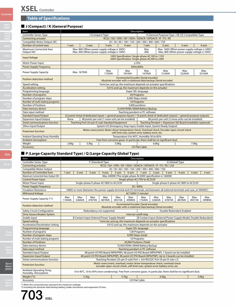
XSEL Controller
703 XSEL
PMECAMEC
Controller
Pulse Motor
Servo Motor (24V)
Servo Motor (200V)
LinearServo Motor
PSEP ASEPDSEP
MSEP
ERC3
ERC2
PCON-CA
PCON
ACON
SCON-CA
MSCON
PSEL
ASEL
SSEL
XSEL
PS-24
J (Compact) / K (General Purpose)Item DescriptionController Series, Type J (Compact) Type K (General Purpose) Type / KE (CE Compatible) TypeConnecting actuator RCS2 / ISA / ISPA / ISP / ISDA / ISDACR / ISPDACR / IF / FS / RSCompatible Motor Output (W) 20 / 30 / 60 / 100 / 150 / 200 / 300 / 400 / 600 / 750Number of control axes 1-axis 2-axis 3-axis 4-axis 1-axis 2-axis 3-axis 4-axisMaximum Connected Axes Output (W)
Max. 800 (When power supply voltage is 200V)Max. 400 (When power supply voltage is 100V)
Max800
Max. 1600 (When power supply voltage is 200V)Max. 800 (When power supply voltage is 100V)
Input Voltage 100V Specification: Single-phase AC100 to 115V200V Specification: Single-phase AC200 to 230V
Motor Power Input ±10%Power Supply Frequency 50Hz/60Hz
Power Supply Capacity Max 1670VA Max1720VA
Max1810VA
Max1670VA
Max3120VA
Max3220VA
Max3310VA
Position detection method Incremental Encoder (Serial encoder)Absolute encoder with a rotational data backup (Serial encoder)
Speed setting 1mm/sec and up, the maximum depends on actuator specificationsAcceleration setting 0.01G and up, the maximum depends on the actuatorProgramming language Super SEL languageNumber of programs 64 ProgramsNumber of program steps 6,000 Steps (total)Number of multi-tasking programs 16 ProgramsNumber of Positions 3,000 positionsData memory device FLASH ROM+SRAM Battery BackupData input method Teaching pendant or PC softwareStandard Input/Output 32 points (total of dedicated inputs + general-purpose inputs) / 16 points (total of dedicated outputs + general-purpose outputs)Expansion Input/Output None 48 points per unit (1 more unit can be installed) 48 points per unit (3 more units can be installed)Serial communications function Teaching Port (25-pin D-sub) Standard Equipment Teaching Pendant + Expansion SIO Board Installable (optional)Other Input/Output System I/O (Emergency Stop Input, Enable Input, System Ready Output)
Protection function Motor overcurrent, Motor driver temperature check, Overload check, Encoder open-circuit checksoft limit over, system error, battery error, etc.
Ambient Operating Temp./Humidity Temperature 0 to 40°C, Humidity 30 to 85%Ambient atmosphere Free from corrosive gases. In particular, there shall be no significant dust.Weight 2.6kg 3.3kg 5.0kg 6.0kg 7.0kgAccessory I/O Flat Cable
*1 When the connected axes represent the maximum wattage.*2 Including the absolute-data backup battery, brake mechanism and expansion I/O box.
P (Large-Capacity Standard Type) / Q (Large-Capacity Global Type)Item DescriptionController Series, Type P (Standard) Type Q (Global) TypeConnecting actuator RCS2 / ISA / ISPA / ISP / ISDA / ISDACR / ISPDACR / IF / FS / RS / LSACompatible Motor Output 20 / 30 / 60 / 100 / 150 / 200 / 300 / 400 / 600 / 750Number of Controlled Axes 1-axis 2-axis 3-axis 4-axis 5-axis 6-axis 1-axis 2-axis 3-axis 4-axis 5-axis 6-axisMaximum Connected Axes Output (W) Max 2400W (The single-phase AC200V specification is 1600W)Control Power Input Single-phase AC170V to AC253VMotor Power Input Single-phase/3-phase AC180V to AC253V Single-phase/3-phase AC180V to AC253VPower Supply Frequency 50 / 60HzInsulation Resistance 10MΩ or more (between the power-supply terminal and I/O terminals, and between all external terminals and case, at 500VDC)Withstand Voltage AC1500V (1 minute)
Power Supply Capacity (*1) Max1744VA
Max3266VA
Max4787VA
Max4878VA
Max4931VA
Max4998VA
Max1744VA
Max3266VA
Max4787VA
Max4878VA
Max4931VA
Max4998VA
Position detection method Incremental Encoder (Serial encoder)Absolute encoder with a rotational data backup (Serial encoder)
Safety Circuit Configuration Redundancy not supported Double Redundant EnabledDrive Source Breaker System Internal cutoff relayEnable Input B Contact Input (Internal Power Supply Model) B Contact Input (External Power Supply Model, Double Redundant)Speed setting 1mm/sec and up, the maximum depends on actuator specificationsAcceleration/Deceleration Setting 0.01G and up, the maximum depends on the actuatorProgramming language Super SEL languageNumber of programs 128 ProgramsNumber of program steps 9,999 Steps (total)Number of multi-tasking programs 16 ProgramsNumber of Positions 20,000 Positions (Total)Data memory device FLASH ROM+SRAM Battery BackupData input method Teaching pendant or PC softwareStandard Input/Output 48-point I/O PIO Board (NPN/PNP), 96-point I/O PIO Board (NPN/PNP), 1 board can be installedExpansion Input/Output 48-point I/O PIO Board (NPN/PNP), 96-point I/O PIO Board (NPN/PNP), Up to 3 boards can be installedSerial communications function Teaching Pendant (25-pin D-sub) Port + 2ch RS232C Port (9-pin D-sub x 2)
Protection function Motor overcurrent, overload, motor driver temperature check, overload checkencoder open-circuit check, soft limit over, system error, battery error, etc.
Ambient Operating Temp. Humidity, Atmosphere 0 to 40°C, 10 to 95% (non-condensing). Free from corrosive gases. In particular, there shall be no significant dust.
Weight (*2) 5.2kg 5.7kg 4.5kg 5.0kgAccessory I/O Flat Cable
Table of Specifications
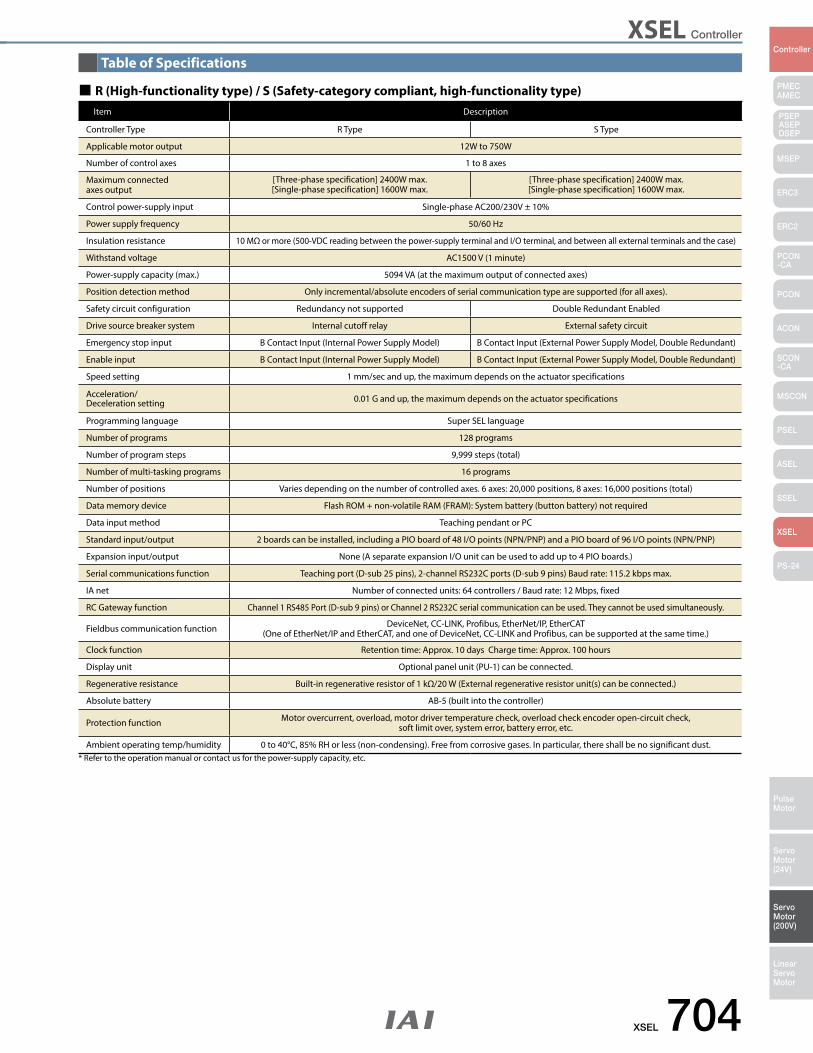
XSEL Controller
XSEL 704
PMECAMEC
Controller
Pulse Motor
Servo Motor (24V)
Servo Motor (200V)
LinearServo Motor
PSEP ASEPDSEP
MSEP
ERC3
ERC2
PCON-CA
PCON
ACON
SCON-CA
MSCON
PSEL
ASEL
SSEL
XSEL
PS-24
R (High-functionality type) / S (Safety-category compliant, high-functionality type) Item Description
Controller Type R Type S Type
Applicable motor output 12W to 750W
Number of control axes 1 to 8 axes
Maximum connected axes output
[Three-phase specification] 2400W max.[Single-phase specification] 1600W max.
[Three-phase specification] 2400W max.[Single-phase specification] 1600W max.
Control power-supply input Single-phase AC200/230V ± 10%
Power supply frequency 50/60 Hz
Insulation resistance 10 MΩ or more (500-VDC reading between the power-supply terminal and I/O terminal, and between all external terminals and the case)
Withstand voltage AC1500 V (1 minute)
Power-supply capacity (max.) 5094 VA (at the maximum output of connected axes)
Position detection method Only incremental/absolute encoders of serial communication type are supported (for all axes).
Safety circuit configuration Redundancy not supported Double Redundant Enabled
Drive source breaker system Internal cutoff relay External safety circuit
Emergency stop input B Contact Input (Internal Power Supply Model) B Contact Input (External Power Supply Model, Double Redundant)
Enable input B Contact Input (Internal Power Supply Model) B Contact Input (External Power Supply Model, Double Redundant)
Speed setting 1 mm/sec and up, the maximum depends on the actuator specifications
Acceleration/Deceleration setting 0.01 G and up, the maximum depends on the actuator specifications
Programming language Super SEL language
Number of programs 128 programs
Number of program steps 9,999 steps (total)
Number of multi-tasking programs 16 programs
Number of positions Varies depending on the number of controlled axes. 6 axes: 20,000 positions, 8 axes: 16,000 positions (total)
Data memory device Flash ROM + non-volatile RAM (FRAM): System battery (button battery) not required
Data input method Teaching pendant or PC
Standard input/output 2 boards can be installed, including a PIO board of 48 I/O points (NPN/PNP) and a PIO board of 96 I/O points (NPN/PNP)
Expansion input/output None (A separate expansion I/O unit can be used to add up to 4 PIO boards.)
Serial communications function Teaching port (D-sub 25 pins), 2-channel RS232C ports (D-sub 9 pins) Baud rate: 115.2 kbps max.
IA net Number of connected units: 64 controllers / Baud rate: 12 Mbps, fixed
RC Gateway function Channel 1 RS485 Port (D-sub 9 pins) or Channel 2 RS232C serial communication can be used. They cannot be used simultaneously.
Fieldbus communication function DeviceNet, CC-LINK, Profibus, EtherNet/IP, EtherCAT(One of EtherNet/IP and EtherCAT, and one of DeviceNet, CC-LINK and Profibus, can be supported at the same time.)
Clock function Retention time: Approx. 10 days Charge time: Approx. 100 hours
Display unit Optional panel unit (PU-1) can be connected.
Regenerative resistance Built-in regenerative resistor of 1 kΩ/20 W (External regenerative resistor unit(s) can be connected.)
Absolute battery AB-5 (built into the controller)
Protection function Motor overcurrent, overload, motor driver temperature check, overload check encoder open-circuit check, soft limit over, system error, battery error, etc.
Ambient operating temp/humidity 0 to 40°C, 85% RH or less (non-condensing). Free from corrosive gases. In particular, there shall be no significant dust.* Refer to the operation manual or contact us for the power-supply capacity, etc.
Table of Specifications
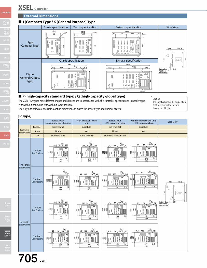
XSEL Controller
705 XSEL
PMECAMEC
Controller
Pulse Motor
Servo Motor (24V)
Servo Motor (200V)
LinearServo Motor
PSEP ASEPDSEP
MSEP
ERC3
ERC2
PCON-CA
PCON
ACON
SCON-CA
MSCON
PSEL
ASEL
SSEL
XSEL
PS-24
External Dimensions
1-axis specification 2-axis specification 3/4-axis specification Side View
J type(Compact Type)
159.42-ø5143.4
120
186
5
191.9
120175.9
186
2-ø5
5
35.9112.5112.5296.8
35.9
186
5
3-ø5
125.3(80)
195
180
(24)Battery Box(Applies to ABS model)
1/2-axis specification 3/4-axis specification
K type(General Purpose
Type)
3-ø5
518
6
34.7 34.7150150
369.43-ø5
5
186
77.2
454.4
77.2150150
Basic Layout(Incremental Specification)
With brake/absoluteunit
Basic Layout + I/O expansion base
With brake/absolute unit+ I/O expansion base Side View
ControllersSpecifications
Encoder Incremental Absolute Incremental Absolute
Brake None Yes None Yes
I/O Standard only Standard only Standard + Expansion
Single phaseSpecifications
1 to 4 axisSpecifications 18
018
619
5
49.5
3-ø5
5
49.5 75 75
265249
180
186
195
3-ø5
5
59.5 75 75 59.5
285269
180
186
195
3-ø5
5
41 120 120 41
338322
180
186
195
3-ø512051
5
120 51
358342
125.3(80)
195
180
(24)Battery Box(Applies to ABS model)
5 to 6 axisSpecifications
284300
180
186
195
22
5
3-ø5
324340
180
186
195
4212012042
5
3-ø5
357373
180
186
195
58.512012058.5
5
3-ø5
397413
18
01
86
19
5
78.512012078.5
5
3-ø5
3 phasesSpecifications
1 to 4 axisSpecifications 18
018
619
5
5
3-ø549.5 75 75 49.5
265249
180
186
195
3-ø5
5
59.5 75 75 59.5
285269
180
186
195
3-ø5
5
41 120 120 41
338322
180
186
195
3-ø5
5
51 120 120 51
358342
5 to 6 axisSpecifications
284300
180
186
195
2212012022
5
3-ø5
324340
180
186
195
4212012042
5
3-ø5
357373
180
186
195
58.512012058.5
5
3-ø5
397413
18
01
86
19
5
78.512012078.5
5
3-ø5
The XSEL-P/Q types have different shapes and dimensions in accordance with the controller specifications (encoder type, with/without brake, and with/without I/O expansion). The 4 layouts below are available. Confirm dimensions to match the desired type and number of axes.
P (high-capacity standard type) / Q (high-capacity global type)
[P Type]
J (Compact) Type / K (General Purpose) Type
CautionThe specifications of the single phase 200V in Q type is the exterior dimension of P type.
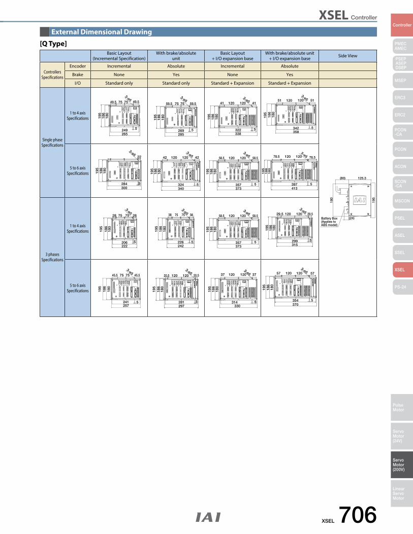
XSEL Controller
XSEL 706
PMECAMEC
Controller
Pulse Motor
Servo Motor (24V)
Servo Motor (200V)
LinearServo Motor
PSEP ASEPDSEP
MSEP
ERC3
ERC2
PCON-CA
PCON
ACON
SCON-CA
MSCON
PSEL
ASEL
SSEL
XSEL
PS-24
External Dimensional Drawing
Basic Layout(Incremental Specification)
With brake/absoluteunit
Basic Layout + I/O expansion base
With brake/absolute unit+ I/O expansion base Side View
ControllersSpecifications
Encoder Incremental Absolute Incremental Absolute
Brake None Yes None Yes
I/O Standard only Standard only Standard + Expansion Standard + Expansion
Single phaseSpecifications
1 to 4 axisSpecifications 18
018
619
549.5
3-ø5
5
49.5 75 75
265249
180
186
195
3-ø5
5
59.5 75 75 59.5
285269
180
186
195
3-ø5
5
41 120 120 41
338322
180
186
195
3-ø512051
5
120 51
358342
125.3(80)
195
180
(24)Battery Box(Applies to ABS model)
5 to 6 axisSpecifications
284300
180
186
195
22
5
3-ø5
324340
180
186
195
4212012042
5
3-ø5
357373
180
186
195
58.512012058.5
5
3-ø5
397413
18
01
86
19
5
78.512012078.5
5
3-ø5
3 phasesSpecifications
1 to 4 axisSpecifications
222206
195
186
180
28757528
5
3-ø5
226242
180
186
195
38757538
5
3-ø5
357373
180
186
195
58.512012058.5
5
3-ø5
299315
180
186
195
29.512012029.5
5
3-ø5
5 to 6 axisSpecifications
241257
180
186
195
45.5757545.5
5
3-ø5
180
186
195
3-ø5
5
20.5 120 120 20.5
297281 314
330
180
186
195
3712012037
5
3-ø5
354370
180
186
195
5712012057
5
3-ø5
[Q Type]
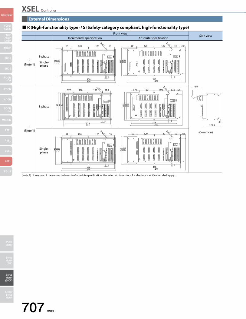
XSEL Controller
707 XSEL
PMECAMEC
Controller
Pulse Motor
Servo Motor (24V)
Servo Motor (200V)
LinearServo Motor
PSEP ASEPDSEP
MSEP
ERC3
ERC2
PCON-CA
PCON
ACON
SCON-CA
MSCON
PSEL
ASEL
SSEL
XSEL
PS-24
External Dimensions
358374
180
186
195
5912012059
5
3-ø5
358402
180
186
195
5912012059
5
3-ø5 (36)
125.3
(80)
3315331
180
186
195
57.510010057.5
5
3-ø5
315359
180
186
195
57.510010057.5
5
3-ø5 (36)
358374
180
186
195
5912012059
5
3-ø5
358402
180
186
195
5912012059
5
3-ø5 (36)
R (High-functionality type) / S (Safety-category compliant, high-functionality type) Front view
Side viewIncremental specification Absolute specification
R(Note 1)
3-phase
Single-phase
(Common)
S(Note 1)
3-phase
Single-phase
(Note 1) If any one of the connected axes is of absolute specification, the external dimensions for absolute specification shall apply.
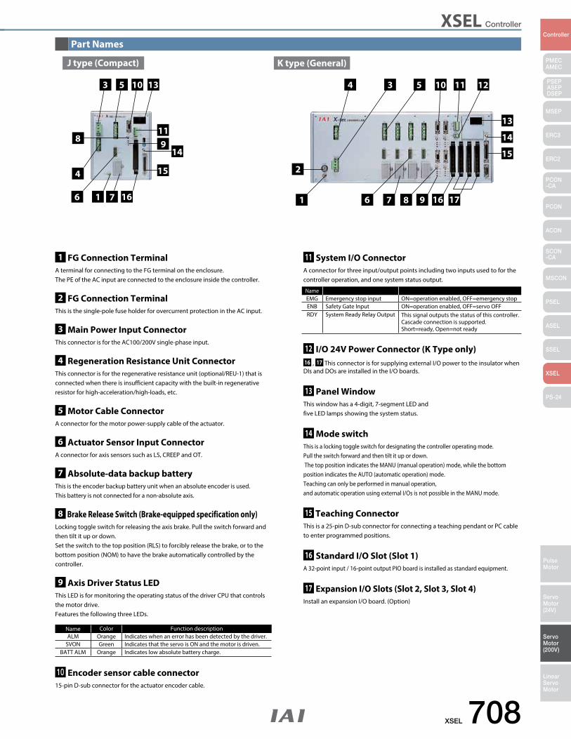
XSEL Controller
XSEL 708
PMECAMEC
Controller
Pulse Motor
Servo Motor (24V)
Servo Motor (200V)
LinearServo Motor
PSEP ASEPDSEP
MSEP
ERC3
ERC2
PCON-CA
PCON
ACON
SCON-CA
MSCON
PSEL
ASEL
SSEL
XSEL
PS-24
Part Names
J type (Compact) K type (General)
3
6
4
61 7 7 8 9 16 1716 1
5 10 13 4 3 5 10 11 12
11
15 2
15
14
13
914
8
1 FG Connection TerminalA terminal for connecting to the FG terminal on the enclosure.The PE of the AC input are connected to the enclosure inside the controller.
2 FG Connection TerminalThis is the single-pole fuse holder for overcurrent protection in the AC input.
3 Main Power Input ConnectorThis connector is for the AC100/200V single-phase input.
4 Regeneration Resistance Unit ConnectorThis connector is for the regenerative resistance unit (optional/REU-1) that is connected when there is insufficient capacity with the built-in regenerative resistor for high-acceleration/high-loads, etc.
5 Motor Cable ConnectorA connector for the motor power-supply cable of the actuator.
6 Actuator Sensor Input ConnectorA connector for axis sensors such as LS, CREEP and OT.
7 Absolute-data backup batteryThis is the encoder backup battery unit when an absolute encoder is used.This battery is not connected for a non-absolute axis.
8 Brake Release Switch (Brake-equipped specification only)Locking toggle switch for releasing the axis brake. Pull the switch forward and then tilt it up or down.Set the switch to the top position (RLS) to forcibly release the brake, or to the bottom position (NOM) to have the brake automatically controlled by the controller.
9 Axis Driver Status LEDThis LED is for monitoring the operating status of the driver CPU that controls the motor drive.Features the following three LEDs.
10 Encoder sensor cable connector15-pin D-sub connector for the actuator encoder cable.
11 System I/O ConnectorA connector for three input/output points including two inputs used to for the controller operation, and one system status output.
12 I/O 24V Power Connector (K Type only)16 , 17 This connector is for supplying external I/O power to the insulator when DIs and DOs are installed in the I/O boards.
13 Panel WindowThis window has a 4-digit, 7-segment LED and five LED lamps showing the system status.
14 Mode switchThis is a locking toggle switch for designating the controller operating mode.Pull the switch forward and then tilt it up or down. The top position indicates the MANU (manual operation) mode, while the bottom position indicates the AUTO (automatic operation) mode.Teaching can only be performed in manual operation,and automatic operation using external I/Os is not possible in the MANU mode.
15 Teaching ConnectorThis is a 25-pin D-sub connector for connecting a teaching pendant or PC cable to enter programmed positions.
16 Standard I/O Slot (Slot 1)A 32-point input / 16-point output PIO board is installed as standard equipment.
17 Expansion I/O Slots (Slot 2, Slot 3, Slot 4)Install an expansion I/O board. (Option)
Name Color Function descriptionALM Orange Indicates when an error has been detected by the driver.
SVON Green Indicates that the servo is ON and the motor is driven.BATT ALM Orange Indicates low absolute battery charge.
NameEMG Emergency stop input ON=operation enabled, OFF=emergency stopENB Safety Gate Input ON=operation enabled, OFF=servo OFFRDY System Ready Relay Output This signal outputs the status of this controller.
Cascade connection is supported.Short=ready, Open=not ready
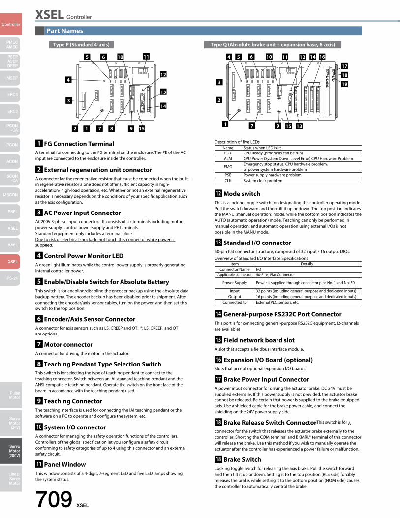
XSEL Controller
709 XSEL
PMECAMEC
Controller
Pulse Motor
Servo Motor (24V)
Servo Motor (200V)
LinearServo Motor
PSEP ASEPDSEP
MSEP
ERC3
ERC2
PCON-CA
PCON
ACON
SCON-CA
MSCON
PSEL
ASEL
SSEL
XSEL
PS-24
Part Names
Type P (Standard 4-axis) Type Q (Absolute brake unit + expansion base, 6-axis)
3
6
4
6
1 72 7 9
16
17
18
19
1
5 10
13
12
4
3
5 10 11 1211
15
2
1598
14
14
13
Description of five LEDsName Status when LED is litRDY CPU Ready (programs can be run)ALM CPU Power (System Down Level Error) CPU Hardware Problem
EMGEmergency stop status, CPU hardware problem, or power system hardware problem
PSE Power supply hardware problemCLK System clock problem
1 FG Connection TerminalA terminal for connecting to the FG terminal on the enclosure. The PE of the AC input are connected to the enclosure inside the controller.
2 External regeneration unit connectorA connector for the regenerative resistor that must be connected when the built-in regenerative resistor alone does not offer sufficient capacity in high-acceleration/ high-load operation, etc. Whether or not an external regenerative resistor is necessary depends on the conditions of your specific application such as the axis configuration.
3 AC Power Input ConnectorAC200V 3-phase input connector. It consists of six terminals including motor power-supply, control power-supply and PE terminals.Standard equipment only includes a terminal block.Due to risk of electrical shock, do not touch this connector while power is supplied.
4 Control Power Monitor LEDA green light illuminates while the control power supply is properly generating internal controller power.
5 Enable/Disable Switch for Absolute BatteryThis switch is for enabling/disabling the encoder backup using the absolute data backup battery. The encoder backup has been disabled prior to shipment. After connecting the encoder/axis-sensor cables, turn on the power, and then set this switch to the top position.
6 Encoder/Axis Sensor ConnectorA connector for axis sensors such as LS, CREEP and OT. *: LS, CREEP, and OT are options.
7 Motor connectorA connector for driving the motor in the actuator.
8 Teaching Pendant Type Selection SwitchThis switch is for selecting the type of teaching pendant to connect to the teaching connector. Switch between an IAI standard teaching pendant and the ANSI-compatible teaching pendant. Operate the switch on the front face of the board in accordance with the teaching pendant used.
9 Teaching ConnectorThe teaching interface is used for connecting the IAI teaching pendant or the software on a PC to operate and configure the system, etc.
10 System I/O connectorA connector for managing the safety operation functions of the controllers. Controllers of the global specification let you configure a safety circuit conforming to safety categories of up to 4 using this connector and an external safety circuit.
11 Panel WindowThis window consists of a 4-digit, 7-segment LED and five LED lamps showing the system status.
12 Mode switchThis is a locking toggle switch for designating the controller operating mode. Pull the switch forward and then tilt it up or down. The top position indicates the MANU (manual operation) mode, while the bottom position indicates the AUTO (automatic operation) mode. Teaching can only be performed in manual operation, and automatic operation using external I/Os is not possible in the MANU mode.
13 Standard I/O connector50-pin flat connector structure, comprised of 32 input / 16 output DIOs.
14 General-purpose RS232C Port ConnectorThis port is for connecting general-purpose RS232C equipment. (2-channels are available)
15 Field network board slotA slot that accepts a fieldbus interface module.
16 Expansion I/O Board (optional)Slots that accept optional expansion I/O boards.
17 Brake Power Input ConnectorA power input connector for driving the actuator brake. DC 24V must be supplied externally. If this power supply is not provided, the actuator brake cannot be released. Be certain that power is supplied to the brake-equipped axis. Use a shielded cable for the brake power cable, and connect the shielding on the 24V power supply side.
18 Brake Release Switch ConnectorThis switch is for A
connector for the switch that releases the actuator brake externally to the controller. Shorting the COM terminal and BKMRL* terminal of this connector will release the brake. Use this method if you wish to manually operate the actuator after the controller has experienced a power failure or malfunction.
18 Brake SwitchLocking toggle switch for releasing the axis brake. Pull the switch forward and then tilt it up or down. Setting it to the top position (RLS side) forcibly releases the brake, while setting it to the bottom position (NOM side) causes the controller to automatically control the brake.
Overview of Standard I/O Interface SpecificationsItem Details
Connector Name I/OApplicable connector 50-Pins, Flat Connector
Power Supply Power is supplied through connector pins No. 1 and No. 50.
Input 32 points (including general-purpose and dedicated inputs)Output 16 points (including general-purpose and dedicated inputs)
Connected to External PLC, sensors, etc.

XSEL Controller
XSEL 710
PMECAMEC
Controller
Pulse Motor
Servo Motor (24V)
Servo Motor (200V)
LinearServo Motor
PSEP ASEPDSEP
MSEP
ERC3
ERC2
PCON-CA
PCON
ACON
SCON-CA
MSCON
PSEL
ASEL
SSEL
XSEL
PS-24
Part Names
12 General-purpose RS232C Port Connectors 1This is a port for connections with external RS232C devices.
13 General-purpose RS232C Port Connectors 2This is a port for connections with external RS232C devices.This port is to be used when using RC Gateway SIO functions (standard).
14 Field Network Board (option) Mounted Position 1The EtherNet/IP or EtherCAT Field Network Board (option) is to be mounted.
15 Field Network Board (option) Mounted Position 2The CC-Link, DeviceNet or PROFIBUS-DP Field Network Board (option) is to be mounted.
16 IA Net ConnectorIn the case that the IA net (option) function is to be added, the dedicated connector is attached. This connector is to be used for connections of IA-Net and expansion I/O units.
17 Teaching ConnectorThis is a connector to connect a teaching pendant or PC (PC software) for teaching tools to have operation and setting of actuators.
18 Brake Release SwitchThis is a switch to compulsorily release (excitation release) the brake of the actuator equipped with a brake. The brake can be compulsorily released by putting the switch on RLS side when a manual operation of an actuator is required for the system startup, teaching or in an error occurrence.Unless otherwise necessary, set the switch on NOM side.
WarningAfter having a brake compulsory release, make sure to set back on NOM (Automatic Mode) so the automatic control of the brake by the controller can be executed. It is extremely risky to leave it on RLS (brake release) status because the brake would not work when in emergency stop or the servo is turned OFF. For a vertically mounted actuator, slider or rod may drop and cause a critical accident.
19 Motor Cable ConnectorIt is the connector to connect the actuator motor cable.
20 FG (Frame Ground) Connection TerminalThis connection terminal is used to connect the FG point on the enclosure to ground. Make sure to ground properly for noise proof reasons.
1 AC Power Input ConnectorAC200V to 230V single or 3-phase input connector. It consists of six terminals including motor power-supply, control power-supply and PE terminals.Due to risk of electrical shock, do not touch this connector while power is supplied.
2 External Regeneration Unit ConnectorThis connector is used to connect a regenerative unit.
3 Encoder ConnectorIt is the connector to connect the actuator and encoder cable.
4 Brake Release Switch ConnectorThe signals of such as an external switch mounted externally to the controller are to be connected and the brake of the actuator equipped with a brake can compulsorily be released (Excitation release).
5 Brake Power Input ConnectorIt is a connector to connect the power supply for brake release for the actuator equipped with a brake. Supply 24V DC, 0.35A (per axis).
6 System I/O ConnectorAn I/O connector that controls the safety operations of the controller. With the S type (safety category compliant), a safety circuit complying with up to category 4 can be configured by having this connector and an external safety circuit.
7 Panel WindowThis shows the controller status with four digits of seven-segment displays and six LED lamps.
8 Panel Unit ConnectorThis is a connector to connect Panel Unit PU-1 (option) for controller status display and error number display.
9 Mode SwitchThis switch is used to specify an operation mode of the controller. It is a toggle switch with safety lever lock. Pull it towards you for operation.
10 I/O Slots 1Either of PIO board (option) or RC Gateway fieldbus board (option) is to be inserted.
11 I/O Slots 2PIO board (Option) is inserted.
R type (High-functionality) S type (Safety-category compliant, high-functionality)
3
2
1
2
1
4 5 6 7
12
11
10
9
8
1314151617181920
3 4 5 6 7
12
11
10
9
8
1314151617181920
Switch Position Function
MANU(Manual Mode) Upper Teaching tool is activated.
AUTO(Automatic Mode)
BottomSide
Teaching tool is inactivated.(Note) For S/SX/SD types, put the enclosed dummy plug to the teaching connector of 19 . Unless it is plugged, the emergency stop would not be released.
Switch Position Function
RLS(Brake Release)
LeftSide To release the brake compulsorily
NOM(Automatic Mode)
RightSide
Brake is controlled automatically by the controller.Servo ON : Brake releaseServo OFF : Brake is activated
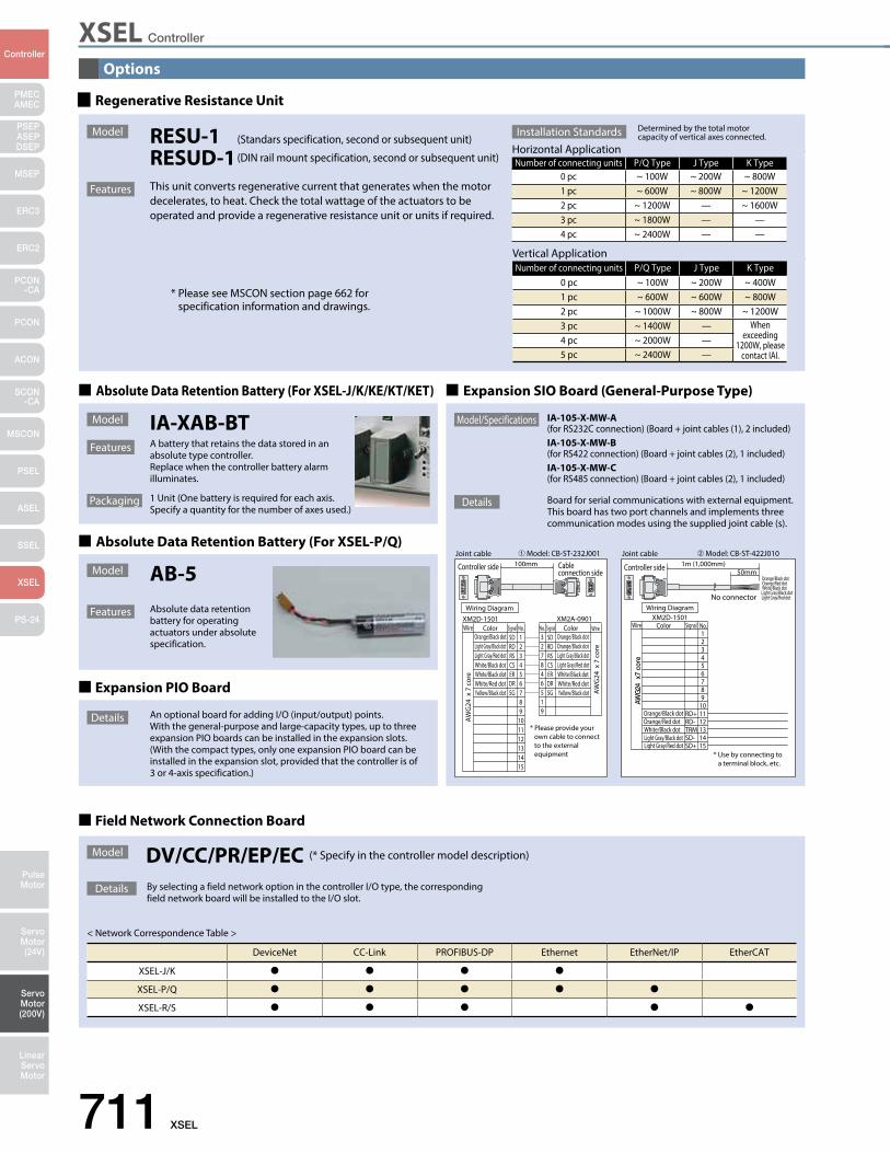
XSEL Controller
711 XSEL
PMECAMEC
Controller
Pulse Motor
Servo Motor (24V)
Servo Motor (200V)
LinearServo Motor
PSEP ASEPDSEP
MSEP
ERC3
ERC2
PCON-CA
PCON
ACON
SCON-CA
MSCON
PSEL
ASEL
SSEL
XSEL
PS-24
Options
Field Network Connection Board
Model DV/CC/PR/EP/EC (* Specify in the controller model description)
Details By selecting a field network option in the controller I/O type, the corresponding field network board will be installed to the I/O slot.
< Network Correspondence Table >
DeviceNet CC-Link PROFIBUS-DP Ethernet EtherNet/IP EtherCAT
XSEL-J/K
XSEL-P/Q
XSEL-R/S
Joint cable Model: CB-ST-232J001➀
Controller side Cable connection side
11
100mm
AW
G24
x 7
cor
e
AW
G24
x 7
cor
e
SDRDRSCSERDRSG
SDRDRSCSERDRSG
123456789
101112131415
327846519
Wiring DiagramXM2A-0901XM2D-1501
WireWire Color ColorOrange/Black dot Orange/Black dot
Orange/Black dotLight Gray/Black dotLight Gray/Red dot Light Gray/Black dot
Light Gray/Red dotWhite/Black dotWhite/Black dot White/Black dotWhite/Red dot White/Red dotYellow/Black dot Yellow/Black dot
Signal SignalNo. No.
* Please provide your own cable to connect to the external equipment * Use by connecting to
a terminal block, etc.
AWG
24
x7 c
ore
1
No connector
XM2D-1501
Orange/Black dotOrange/Red dot
Light Gray/Black dotLight Gray/Red dot
White/Black dot
Orange/Black dotOrange/Red dot
Light Gray/Black dotLight Gray/Red dot
White/Black dot
Joint cable Model: CB-ST-422J010➁
Controller side 1m (1,000mm)50mm
123456789
101112131415
RD+RD-TRMSD-SD+
Wiring Diagram
Wire Color Signal No.
Regenerative Resistance Unit
Expansion SIO Board (General-Purpose Type)
Expansion PIO Board
Details An optional board for adding I/O (input/output) points.With the general-purpose and large-capacity types, up to three expansion PIO boards can be installed in the expansion slots.(With the compact types, only one expansion PIO board can be installed in the expansion slot, provided that the controller is of 3 or 4-axis specification.)
Details Board for serial communications with external equipment.This board has two port channels and implements three communication modes using the supplied joint cable (s).
Model/Specifications IA-105-X-MW-A(for RS232C connection) (Board + joint cables (1), 2 included)IA-105-X-MW-B(for RS422 connection) (Board + joint cables (2), 1 included)IA-105-X-MW-C(for RS485 connection) (Board + joint cables (2), 1 included)
ø5
16.6 126
34
5
175
195
186
Number of connecting units P/Q Type J Type K Type0 pc ~ 100W ~ 200W ~ 400W1 pc ~ 600W ~ 600W ~ 800W2 pc ~ 1000W ~ 800W ~ 1200W3 pc ~ 1400W — When
exceeding 1200W, please
contact IAI.4 pc ~ 2000W —5 pc ~ 2400W —
Number of connecting units P/Q Type J Type K Type0 pc ~ 100W ~ 200W ~ 800W1 pc ~ 600W ~ 800W ~ 1200W2 pc ~ 1200W — ~ 1600W3 pc ~ 1800W — —4 pc ~ 2400W — —
Horizontal ApplicationInstallation Standards Determined by the total motor
capacity of vertical axes connected.
Vertical Application
Model RESU-1 (Standars specification, second or subsequent unit)
RESUD-1 (DIN rail mount specification, second or subsequent unit)
* Please see MSCON section page 662 for specification information and drawings.
Features This unit converts regenerative current that generates when the motor decelerates, to heat. Check the total wattage of the actuators to be operated and provide a regenerative resistance unit or units if required.
Absolute Data Retention Battery (For XSEL-J/K/KE/KT/KET)
Model
Features
Packaging
IA-XAB-BTA battery that retains the data stored in an absolute type controller.Replace when the controller battery alarm illuminates.
1 Unit (One battery is required for each axis. Specify a quantity for the number of axes used.)
Absolute Data Retention Battery (For XSEL-P/Q)
Model
Features
AB-5Absolute data retention battery for operating actuators under absolute specification.
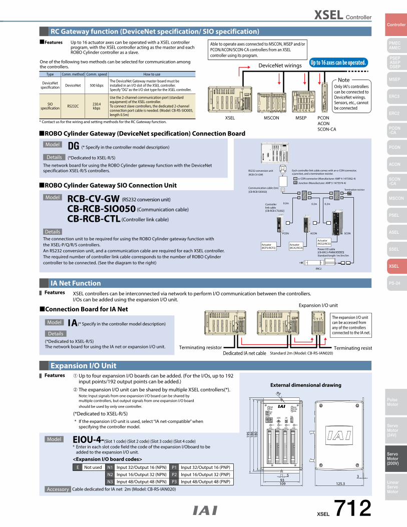
XSEL Controller
XSEL 712
PMECAMEC
Controller
Pulse Motor
Servo Motor (24V)
Servo Motor (200V)
LinearServo Motor
PSEP ASEPDSEP
MSEP
ERC3
ERC2
PCON-CA
PCON
ACON
SCON-CA
MSCON
PSEL
ASEL
SSEL
XSEL
PS-24
RC Gateway function (DeviceNet specification/ SIO specification)
e-CON connector (Manufacturer: AMP 4-1473562-4)
Each controller link cable comes with an e-CON connector,a junction, and a termination resistor.
Junction (Manufacturer: AMP 5-1473574-4)
Termination resistor
0.2m0.2m0.2m
PCON
ERC2
ACON SCON
Power I/O cable[CB-ERC2-PWBIO]Standard length 1m/3m/5m
Controllerlink cable[CB-RCB-CTL002]
Actuator[RCP3/RCP2]
Actuator[RCA2/RCA]
Actuator[RCS2/RCS3
RS232 conversion unit[RCB-CV-GW]
Communication cable (5m)[CB-RCB-SIO050]
ROBO Cylinder Gateway SIO Connection Unit
ROBO Cylinder Gateway (DeviceNet specification) Connection Board
Model
Model
Details
DetailsThe connection unit to be required for using the ROBO Cylinder gateway function with the XSEL-P/Q/R/S controllers.An RS232 conversion unit, and a communication cable are required for each XSEL controller.The required number of controller link cable corresponds to the number of ROBO Cylinder controller to be connected. (See the diagram to the right)
The network board for using the ROBO Cylinder gateway function with the DeviceNet specification XSEL-R/S controllers.
RCB-CV-GW (RS232 conversion unit)
CB-RCB-SIO050 (Communication cable)
CB-RCB-CTL (Controller link cable)
DG (* Specify in the controller model description)
(*Dedicated to XSEL-R/S)
Type Comm. method Comm. speed How to use
DeviceNet specification DeviceNet 500 kbps
The DeviceNet Gateway master board must be installed in an I/O slot of the XSEL controller. Specify “DG” as the I/O slot type for the XSEL controller.
SIO specification RS232C 230.4
kbps
Use the 2-channel communication port (standard equipment) of the XSEL controller. To connect slave controllers, the dedicated 2-channel connection port cable is needed. (Model: CB-RS-SIO005, length 0.5m)
* Contact us for the wiring and setting methods for the RC Gateway function.
Up to 16 actuator axes can be operated with a XSEL controller program, with the XSEL controller acting as the master and each ROBO Cylinder controller as a slave.
One of the following two methods can be selected for communication among the controllers.
Up to 16 axes can be operated.
XSEL MSCON MSEP PCONACONSCON-CA
DeviceNet wirings
Able to operate axes connected to MSCON, MSEP and/or PCON/ACON/SCON-CA controllers from an XSEL controller using its program.
Only IAI’s controllerscan be connected to DeviceNet wirings. Sensors, etc., cannot be connected
Note
Features
IA Net Function
Expansion I/O unit
Terminating resistor Terminating resistorDedicated IA net cable Standard 2m (Model: CB-RS-IAN020)
The expansion I/O unit can be accessed from any of the controllers connected to the IA net.
XSEL controllers can be interconnected via network to perform I/O communication between the controllers.I/Os can be added using the expansion I/O unit.
Connection Board for IA Net
Model
Details(*Dedicated to XSEL-R/S)The network board for using the IA net or expansion I/O unit.
IA(* Specify in the controller model description)
Features
Expansion I/O Unit
125.310993
195
186
180
5
ø5
3
I/O1 I/O2 I/O3 I/O4
ALMC-ERR
PWRPSE24V0V
LINK
PNLSW
IA-NETADRS
1 40
4C
8RDY1 RDY2 RDY3 RDY4
External dimensional drawing
<Expansion I/O board codes>
E Not used N1 Input 32/Output 16 (NPN) P1 Input 32/Output 16 (PNP)
N2 Input 16/Output 32 (NPN) P2 Input 16/Output 32 (PNP)
N3 Input 48/Output 48 (NPN) P3 Input 48/Output 48 (PNP)
➀ Up to four expansion I/O boards can be added. (For the I/Os, up to 192 input points/192 output points can be added.)
➁ The expansion I/O unit can be shared by multiple XSEL controllers(*). Note: Input signals from one expansion I/O board can be shared by multiple controllers, but output signals from one expansion I/O board should be used by only one controller.
(*Dedicated to XSEL-R/S) * If the expansion I/O unit is used, select “IA net-compatible” when specifying the controller model.
EIOU-4-(Slot 1 code) (Slot 2 code) (Slot 3 code) (Slot 4 code) * Enter in each slot code field the code of the expansion I/Oboard to be added to the expansion I/O unit.
Features
Model
Accessory Cable dedicated for IA net 2m (Model: CB-RS-IAN020)

XSEL Controller
713 XSEL
PMECAMEC
Controller
Pulse Motor
Servo Motor (24V)
Servo Motor (200V)
LinearServo Motor
PSEP ASEPDSEP
MSEP
ERC3
ERC2
PCON-CA
PCON
ACON
SCON-CA
MSCON
PSEL
ASEL
SSEL
XSEL
PS-24
Options
TP adapter for SEL-TGIA-LB-TGS
Conversion cableCB-SEL-SJS002
(Option)
Conversion cableCB-SEL-SJS002(Accessory)
5m
5m
0.2m Controller cable forPSEL/ASEL /SSEL
CB-SEL26H-LBS005
0.5m
Controller cable forXSEL controller
CB-SEL25-LBS005
0.5m
ASELPSEL SSEL
XSEL
SEL-TD-JS
DC24VXSEL-Jonly
SafetyCircuit
<SEL-TD-26H>
<SEL-TD-25>
<SEL-TD>
Wiring drawing
Teaching pendant - controller correspondence table
SEL-TSplash-proof type
SEL-TDANSI compliant splash-proof type
SEL-TD-26H/SEL-TD-25Safety-category compliant type
ProgramControllers
PSEL/ASEL/SSELXSEL-JXSEL-KXSEL-PXSEL-QXSEL-KTXSEL-KE
* SEL-TD can be directly connected to the controller. SEL-TG connects to the controller via the TP adapter.Function of the teaching pendant bodies are the same.
The structures of following model options are as follows.
<Model: SEL-TD-26H>• Teaching pendant <Model: SEL-TD-JS>• TP adapter for SEL <Model: IA-LB-TGS>• Controller connection cable <Model: CB-SEL26H-LBS005>• Dummy plug <Model: DP-4S>
• Teaching pendant <Model: SEL-TD-JS>• TP adapter for SEL <Model: IA-LB-TGS>• Controller connection cable <Model: CB-SEL25H-LBS005>• Dummy plug <Model: DP-4S>
<Model: SEL-TD-25>
Details
(Note 1) (Note 1)(Note 2)
* corresponds to safety category B to 4. does not correspond to safety category, but connection is available.
(Note 1) To connect to PSEL/ASEL/SSEL, a conversion cable is necessary.(Note 2) To connect SEL-TG to the XSEL-J/JX controller, DC24V needs to be applied to TP adaptor.
* The SEL-TG teaching pendant body is CE supported, however, IA-LB-TG is not.
(*) only SEL-TD / SEL-TG corresponds to ANSI standard.
110.0
218.
3
66.6
39.046.9
89.6
ANSI standard / CE mark compatible teaching pendant (dedicated to general purpose type)
Dimensions
Splash-proof type that corresponds to protection level IP54. Improved operationability with separate keys for different functions. In addition, SEL-TD / SEL-TG has a 3-position enable switch and corresponds to ANSI standard.
SEL-TSEL-TD ANSI compliant
SEL-TD-26H Safety-category compliant, for PSEL/ASEL/SSEL
SEL-TD-25 Safety-category compliant, for XSEL
Model
Features
Item SpecificationsAmbient Operating Temp./Humidity Temperature: 0 to 40ºC Humidity: 30 to 85%RH or lower (non-condensing)Protection mechanism IP54 (Cable connector excluded)Weight 400g or lower (Cable connector excluded)Cable Length 5mIndication 32 characters x 8 lines LCD displaySafety Rating CE mark, ANSI standard (*)
Specifications
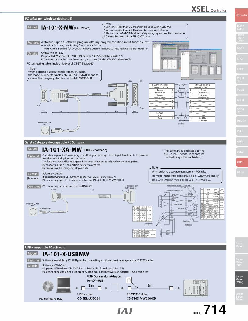
XSEL Controller
XSEL 714
PMECAMEC
Controller
Pulse Motor
Servo Motor (24V)
Servo Motor (200V)
LinearServo Motor
PSEP ASEPDSEP
MSEP
ERC3
ERC2
PCON-CA
PCON
ACON
SCON-CA
MSCON
PSEL
ASEL
SSEL
XSEL
PS-24
15.548.55m4215
Wiring Diagram
1
2233
445
5
667
Connector hood FG Connector hood FG
(Shield)
8 201819
7
1312
12
Shield FG
D-Sub/25-pin plugD-Sub/9-pin socket
ELP-02V
BlackRed
Orange Orange
Brown BrownBrown/Black Brown/Black
Orange/BlackOrange/Black
RedRed/Black
1
13 25
1
5
14
6
9
Emergency stop box
5m3m
PC Software (CD)RS232C CableCB-ST-E1MW050-EB
USB cableCB-SEL-USB030
USB Conversion AdapterIA−CV−USB
USB-compatible PC software
Model
Features Software available by PC USB port by connecting a USB conversion adaptor to a RS232C cable.
Software (CD-ROM)(Supported Windows OS: 2000 SP4 or later / XP SP2 or later / Vista / 7) PC connecting cable 5m + Emergency stop box + USB conversion adaptor + USB cable 3m
IA-101-X-USBMW
Details
short circuit
short circuit
Connect shielding to pin 1 and case
short circuit
3
SW1. NC22(EMG2)SW1. NC21(EMG2)SW1. NC12(EMG1)SW1. NC11(EMG1)
SignalNo.
4321
YellowWire
0. 25sq
Color
YellowGreenBrownWhite
21
34
WhiteBrownGreen
Junction shellSoldered inside
87645
WhiteBrown
YellowGreen
White
GreenBrown
Yellow
BlackPurple
WireSignalNo.
(short circuit)
Connect to case
(short circuit)
ShieldCTS
DSRRTS
876
DTRSG
RXDTXD
45
23
Color
Purple/Black
Red/BlueGray/Pink
0. 3sq
0. 3sq
0. 25sq
2
Connect shielding to case
Red/BlueShield
Gray/Pink CTS54Black/Purple
16
short circuit
White 24
GreenBrown
Yellow
PurpleBlack
1312222119
206
17
57
2416
Shield
22
1312
21191720
76 DSR
DTR
SG
Connect to case
0. 25sq
WhiteBrown
0. 3sq(short circuit)
0. 3sq
YellowGreen
(short circuit)
0. 25sq
0. 3sq(short circuit)
Red/BlueRed/BlueShield
Gray/Pink
short circuit
1
32
4321
No.
RTS
TXDRXD
FG (Shield)Signal
0. 25sq
0. 3sq
Gray/Pink(short circuit)
Color WirePC side
EMG SW Box side
5mRelay box side
Teaching pendant
SW1. NC22(EMG2)SW1. NC21(EMG2)
SW2. C12(ENB1)
SW2. C22(ENB2)SW2. C21(ENB2)
SW1. NC12(EMG1)SW1. NC11(EMG1)
SW2. C11(ENB1)Emergency stop
box
Safety Category 4-compatible PC Software
Model
Features A startup support software program offering program/position input function, test operation function, monitoring function, and more. The functions needed for debugging have been enhanced to help reduce the startup time.PC connecting cable is compatible to safety category 4by duplicating the emergency stop circuits.
IA-101-XA-MW (DOS/V version)
PC connecting cable (Model: CB-ST-A1MW050)Dimensions
Software (CD-ROM)(Supported Windows OS: 2000 SP4 or later / XP SP2 or later / Vista / 7)PC connecting cable 5m + Emergency stop box (Model: CB-ST-A1MW050-EB)
Details(Accessory)
When ordering a separate replacement PC cable,
the model number for cable only is CB-ST-A1MW050, and for
cable with emergency stop box is CB-ST-A1MW050-EB.
Note:
* The software is dedicated to the XSEL-KT/KET/Q/QX. It cannot be used with any other controllers.
PC software (Windows dedicated)
Features A startup support software program offering program/position input function, test operation function, monitoring function, and more. The functions needed for debugging have been enhanced to help reduce the startup time.
Details Software (CD-ROM)(Supported Windows OS: 2000 SP4 or later / XP SP2 or later / Vista / 7)PC connecting cable 5m + Emergency stop box (Model: CB-ST-E1MW050-EB)
PC connecting cable single unit (Model: CB-ST-E1MW050)
Model IA-101-X-MW (DOS/V ver.) * Versions older than 3.0.0 cannot be used with XSEL-P/Q. * Versions older than 2.0.0 cannot be used with SCARA. * Please use IA-101-XA-MW for safety category 4-compliant controller.* Cannot be used with XSEL-Q/QX types.
Note
When ordering a separate replacement PC cable,the model number for cable only is CB-ST-E1MW050, and for cable with emergency stop box is CB-ST-E1MW050-EB.
Note
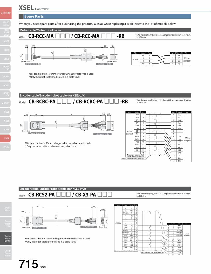
XSEL Controller
715 XSEL
PMECAMEC
Controller
Pulse Motor
Servo Motor (24V)
Servo Motor (200V)
LinearServo Motor
PSEP ASEPDSEP
MSEP
ERC3
ERC2
PCON-CA
PCON
ACON
SCON-CA
MSCON
PSEL
ASEL
SSEL
XSEL
PS-24
When you need spare parts after purchasing the product, such as when replacing a cable, refer to the list of models below.
Controller side Actuator side
L
4
1
1
4
Wire Signal
0.75sq
PE 1WireSignal
0.75sq(crimped)
U1
(16) (20) (20) (10)
(Front view) (Front view)
(41)
(ø9) (2
1)
(18)
UVW
234
234
VWPE
No. No.
Model CB-RCC-MA / CB-RCC-MA -RBMotor cable/Motor robot cable
* Enter the cable length (L) into . Compatible to a maximum of 30 meters. Ex.: 080 = 8m
Min. bend radius r = 50mm or larger (when movable type is used)* Only the robot cable is to be used in a cable track
Controller side Actuator side
Wire Signal
0.15sq
(crimped)
A/U 1
The shield is connected to the hood by a clamp.
WireSignal
0.15sq
(crimped)
A/U1
Ground wire and shield braiding
L
1,10
9,18
(ø8)
(36)
(16)
(Front view)
(33)
(57)
(Front view)
(15)(14)(2
5)
A/U
B/V
B/V
Z/W
Z/W
SD
SD
BAT+
BAT−
VCC
GND
BK−
BK+
–
2
3
4
5
6
7
8
9
10
11
12
13
14
15
2
3
4
5
6
7
8
9
10
11
12
13
14
15
16
17
18
A/U
B/V
B/V
Z/W
Z/W
–
–
FG
SD
SD
BAT+
BAT−
VCC
GND
–
BK−
BK+
No. No.
Encoder cable/Encoder robot cable (for XSEL-J/K)
Model CB-RCBC-PA / CB-RCBC-PA -RB * Enter the cable length (L) into . Compatible to a maximum of 30 meters. Ex.: 080 = 8 m
Min. bend radius r = 50mm or larger (when movable type is used)* Only the robot cable is to be used in a cable track
1
9
1
13
14
2618
10
L
Ground wire and shield braiding GrayRed
Brown
YellowGreen
Black
Green/White AWG26(crimped)
Orange
GroundBlue
Blue/redOrange/White
WhitePurple
Pink
15161718
1413121110
6
987
3
54
21
No.
BK−BK+
GNDLS-
BAT+BAT−VCC
Z
FGSD
SD
LS+
B
ZB
AA
Signal Color Wire
The shield is connected to the hood by a clamp.
AWG26(soldered)
Wire
212017
22
6
16151487
3
54
21
25
1819
2324
9
1011121326
No.
BKR+BKR-GND
Z−
BAT+
VCCBAT−
SRD-SRD+
B+
Z+B−
A−A+
CREEPOTRSV
E24V0VLS
Signal
Brown/White
Gray/White
Brown
RedGray
Green/WhiteOrange/White
WhiteBlue/red
Purple
GreenYellowBlack
Blue
Pink
Orange
Color
Brown/WhiteGray/White
(ø10
)
(41) (14)
Controller side
(13)
(37)
Actuator side(Front view) (Front view)
(15)
(25)
Encoder cable/Encoder robot cable (for XSEL-P/Q)
Model CB-RCS2-PA / CB-X3-PA * Enter the cable length (L) into . Compatible to a maximum of 30 meters. Ex.: 080 = 8 m
Min. bend radius r = 50mm or larger (when movable type is used)* Only the robot cable is to be used in a cable track
Spare Parts
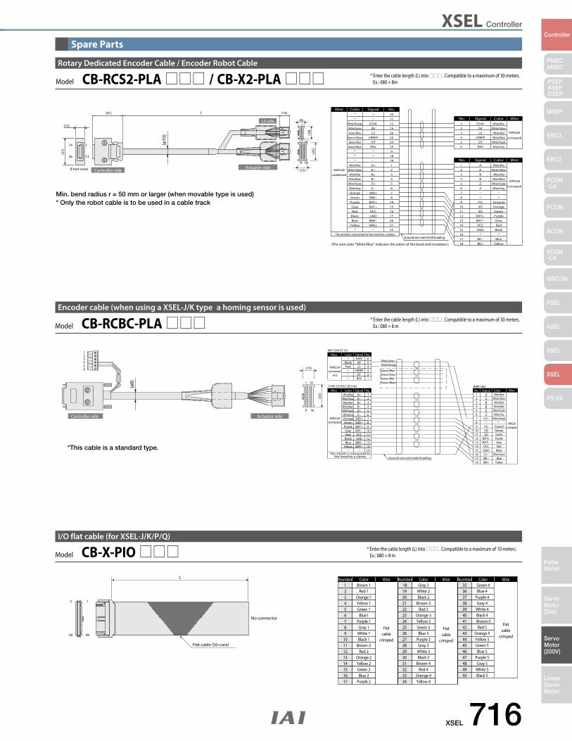
XSEL Controller
XSEL 716
PMECAMEC
Controller
Pulse Motor
Servo Motor (24V)
Servo Motor (200V)
LinearServo Motor
PSEP ASEPDSEP
MSEP
ERC3
ERC2
PCON-CA
PCON
ACON
SCON-CA
MSCON
PSEL
ASEL
SSEL
XSEL
PS-24
Ground wire and shield braiding
(crimped)
AWG26
AWG26
(soldered)
10
White/BlueA1
Wire Color Signal No.
WireColorSignalNo.
The shield is connected to the hood by a clamp.
(The wire color "White/Blue" indicates the colors of the band and insulation.)
(crimped)
AWG26
White/BlueE24V1
WireColorSignalNo.
1
9
1
13
14
26
18
10
L
6
1
(ø10
)Controller side
Actuator side
LS side(13)
(41) (14)
(37)
(Front view)
(8)
(15)
(18)
(25)
White/Orange
White/Green
Brown/Blue
Brown/Yellow
Brown/Red
Brown/Black
White/Blue
White/Yellow
White/Red
White/Black
White/Purple
White/Gray
Orange
Green
Purple
Gray
Red
Black
Blue
Yellow
E24V
0V
LS
CREEP
OT
RSV
A+
A−
B+
B−
Z+
Z−
SRD+
SRD−
BAT+
BAT−
VCC
GND
BKR−
BKR+
11
12
13
26
25
24
23
9
18
19
1
2
3
4
5
6
7
8
14
15
16
17
20
21
22
2
3
4
5
6
0V
LS
CREEP
OT
RSV
White/Yellow
White/Red
White/Black
White/Purple
White/Gray
2
3
4
5
6
7
8
9
10
11
12
13
14
15
16
17
18
A
B
B
Z
Z
FG
SD
SD
BAT+
BAT−
VCC
GND
BK−
BK+
White/Yellow
White/Red
White/Black
White/Purple
White/Gray
Ground
Orange
Green
Purple
Gray
Red
Black
Blue
Yellow
Min. bend radius r = 50 mm or larger (when movable type is used)* Only the robot cable is to be used in a cable track
Rotary Dedicated Encoder Cable / Encoder Robot Cable
Model CB-RCS2-PLA / CB-X2-PLA * Enter the cable length (L) into . Compatible to a maximum of 30 meters. Ex.: 080 = 8m
1
9 18
10
56
4
23
1
The shield is connected to the hood by a clamp.
GND
Ground wire and shield braiding
23
15
4
MC1.5/6-ST-3.5
BAT+BAT−
Wire Color Signal No.
(crimped)
5
98
67
Ground
Wire
AWG26
43
SDSD
21
XMP-18VNo. Signal Color
VCC
876
45
3
12
A+A−B+B−Z+Z−
SRD+SRD−
BKR−BKR+
RSVOT
CREEPLS
1011121314
1
56
0VE24V
1011121314
18171615
BK+BK−
GNDVCC
BAT−BAT+
FG
AABBZZ
BlueYellow
GrayRed
Black
Green
White/Blue
Orange
Purple
White/Yellow
White/BlackWhite/Red
White/PurpleWhite/Gray White/Gray
White/PurpleWhite/BlackWhite/Red
White/YellowWhite/Blue
Black
GreenOrange
GrayPurple
Red
YellowBlue
LS+
LS− White/Green
White/OrangeAWG26(crimped)
AWG24(screwed
on)
Wire Color Signal No.
9
White/GreenWhite/Orange
BlackRed
17HE-23150-C (D13A)
Controller side Actuator side
(ø8)
(15)
(25)
Brown/BlueBrown/YellowBrown/RedBrown/Black
Encoder cable (when using a XSEL-J/K type a homing sensor is used)
*This cable is a standard type.
Model CB-RCBC-PLA * Enter the cable length (L) into . Compatible to a maximum of 30 meters. Ex.: 080 = 8 m
23456789
1011121314151617
L
Flat cable (50-core)
No connector
2 1
50 49
ColorNumber Wire
Flatcable
crimped
Wire
Flatcable
crimped
Wire
Flatcable
crimped
ColorNumber ColorNumber1 Brown 1 18 Gray 2 35 Green 4
Red 1Orange 1Yellow 1Green 1
Blue1Purple 1Gray 1
White 1Black 1
Brown-2Red 2
Orange 2Yellow 2Green 2Blue 2
Purple 2
19202122232425262728293031323334
White 2Black 2
Brown-3Red 3
Orange 3Yellow 3Green 3Blue 3
Purple 3Gray 3
White 3Black 3
Brown-4Red 4
Orange 4Yellow 4
363738394041424344454647484950
Blue 4Purple 4Gray 4
White 4Black 4Brown-5Red 5
Orange 5Yellow 5Green 5Blue 5
Purple 5Gray 5
White 5Black 5
I/O flat cable (for XSEL-J/K/P/Q)
Model CB-X-PIO * Enter the cable length (L) into . Compatible to a maximum of 10 meters. Ex.: 080 = 8 m
Spare Parts
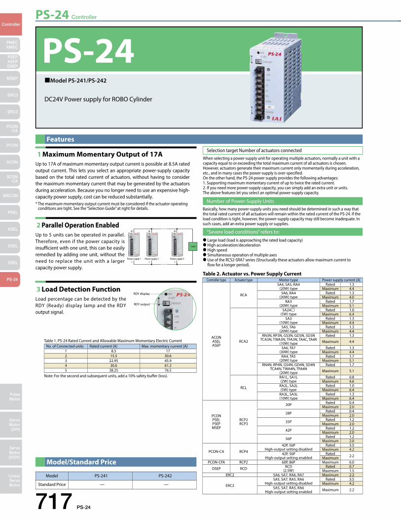
PS-24 Controller
717 PS-24
PMECAMEC
Controller
Pulse Motor
Servo Motor (24V)
Servo Motor (200V)
LinearServo Motor
PSEP ASEPDSEP
MSEP
ERC3
ERC2
PCON-CA
PCON
ACON
SCON-CA
MSCON
PSEL
ASEL
SSEL
XSEL
PS-24
FeaturesSelection target Number of actuators connected
Number of Power-Supply Units
“Severe load conditions” refers to:
1 Maximum Momentary Output of 17A Up to 17A of maximum momentary output current is possible at 8.5A rated output current. This lets you select an appropriate power-supply capacity based on the total rated current of actuators, without having to consider the maximum momentary current that may be generated by the actuators during acceleration. Because you no longer need to use an expensive high-capacity power supply, cost can be reduced substantially.* The maximum momentary output current must be considered if the actuator operating
conditions are tight. See the “Selection Guide” at right for details.
2 Parallel Operation Enabled Up to 5 units can be operated in parallel. Therefore, even if the power capacity is insufficient with one unit, this can be easily remedied by adding one unit, without the need to replace the unit with a larger capacity power supply.
3 Load Detection Function Load percentage can be detected by the RDY (Ready) display lamp and the RDY output signal.
Model PS-241 PS-242
Standard Price — —
Controller type Actuator type Motor type Power supply current [A
ACONASELASEP
RCA
SA4, SA5, RA4(20W) type
Rated 1.3 Maximum 4.4
SA6, RA4(30W) type
Rated 1.3 Maximum 4.0
RA3(20W) type
Rated 1.7 Maximum 5.1
RCA2
SA2A(5W) type
Rated 1.0Maximum 6.4
SA3(10W) type
Rated 1.3 Maximum 4.4
SA5, TA6(20W) type
Rated 1.3 Maximum 4.4
RN3N, RP3N, GS3N, GD3N, SD3NTCA3N, TWA3N, TFA3N, TA4C, TA4R
(10W) type
Rated 1.3
Maximum 4.4
SA6, TA7(30W) type
Rated 1.3 Maximum 4.4
RA4, TA5(20W) type
Rated 1.7 Maximum 5.1
RN4N, RP4N, GS4N, GD4N, SD4NTCA4N, TWA4N, TFA4N
(20W) type
Rated 1.7
Maximum 5.1
RCL
RA1L, SA1L(2W) type
Rated 0.8 Maximum 4.6
RA2L, SA2L(5W) type
Rated 1.0 Maximum 6.4
RA3L, SA3L(10W) type
Rated 1.3 Maximum 6.4
PCONPSELPSEPMSEP
RCP2RCP3
20P Rated 0.4 Maximum 2.0
28P Rated 0.4 Maximum 2.0
35P Rated 1.2Maximum 2.0
42P Rated 1.2 Maximum 2.0
56P Rated 1.2 Maximum 2.0
PCON-CA RCP4
42P, 56PHigh-output setting disabled
Rated 3.5Maximum 4.2
42P, 56PHigh-output setting enabled
Rated 2.2MaximumPCON-CFA RCP2 60P, 86P Maximum 6.0
DSEP RCD RCD(2.5W)
Rated 0.7Maximum 1.5
ERC2 SA6, SA7, RA6, RA7 Maximum 2.2
ERC3
SA5, SA7, RA5, RA6High-output setting disabled
Rated 3.5Maximum 4.2
SA5, SA7, RA5, RA6High-output setting enabled Maximum 2.2
Table 2. Actuator vs. Power Supply Current
No. of Connected units Rated current [A] Max. momentary current [A]1 8.5 172 15.5 30.63 22.95 45.94 30.6 61.25 38.25 76.5
Table 1. PS-24 Rated Current and Allowable Maximum Momentary Electric Current
Note: For the second and subsequent units, add a 10% safety buffer (loss).
Model/Standard Price
When selecting a power-supply unit for operating multiple actuators, normally a unit with a capacity equal to or exceeding the total maximum current of all actuators is chosen. However, actuators generate their maximum current only momentarily during acceleration, etc., and in many cases the power-supply is over-specified. On the other hand, the PS-24 power supply provides the following advantages:1. Supporting maximum momentary current of up to twice the rated current.2. If you need more power-supply capacity, you can simply add an extra unit or units.The above features let you select an optimal power-supply capacity.
Basically, how many power-supply units you need should be determined in such a way that the total rated current of all actuators will remain within the rated current of the PS-24. If the load condition is tight, however, the power-supply capacity may still become inadequate. In such cases, add an extra power supply or supplies.
Large load (load is approaching the rated load capacity) High acceleration/deceleration High speed Simultaneous operation of multiple axes Use of the RCS2-SRA7 series (Structurally these actuators allow maximum current to flow for a longer period).
Power supply 1 Power supply 2 Power supply 5
Load
RDY display
RDY output
PS-24DC24V Power supply for ROBO Cylinder
Model PS-241/PS-242
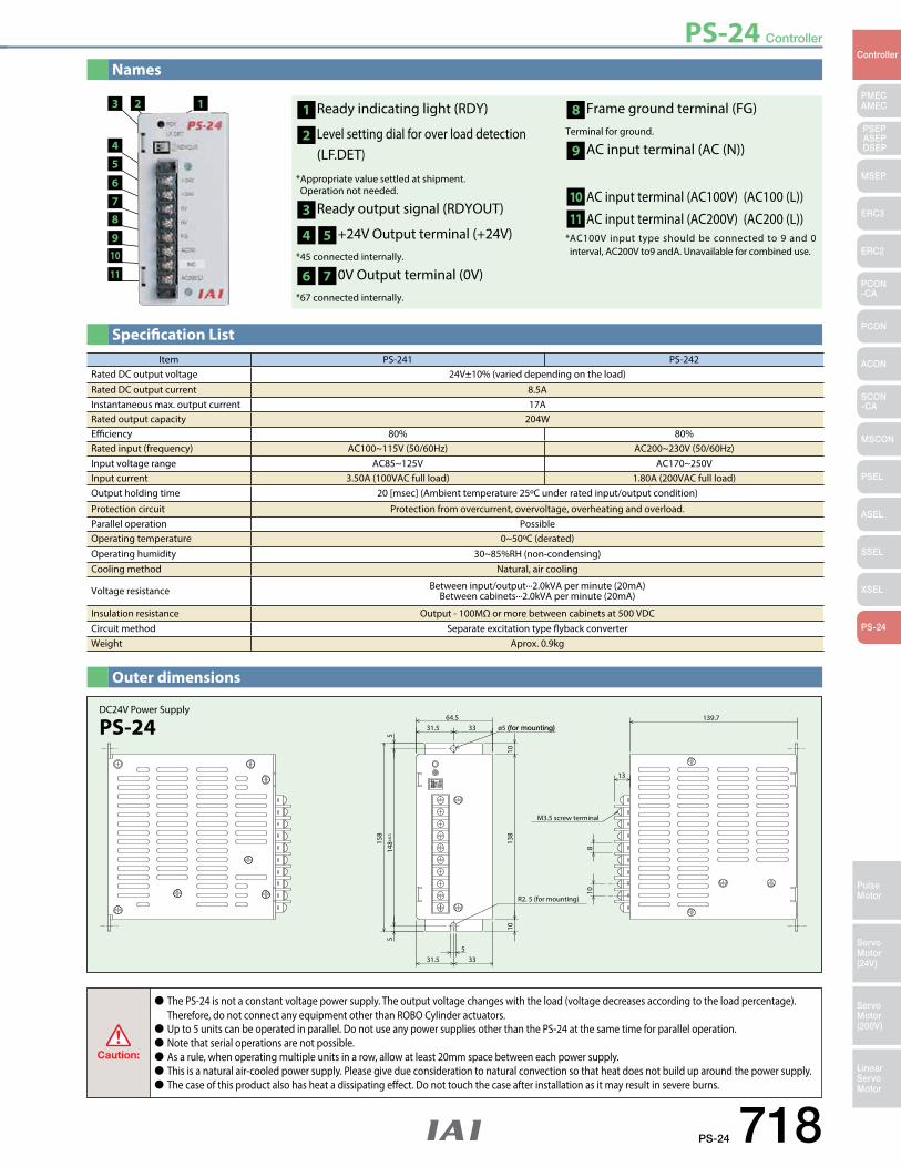
PS-24 Controller
PS-24 718
PMECAMEC
Controller
Pulse Motor
Servo Motor (24V)
Servo Motor (200V)
LinearServo Motor
PSEP ASEPDSEP
MSEP
ERC3
ERC2
PCON-CA
PCON
ACON
SCON-CA
MSCON
PSEL
ASEL
SSEL
XSEL
PS-24
Names
Specification List
Outer dimensions
Caution:
The PS-24 is not a constant voltage power supply. The output voltage changes with the load (voltage decreases according to the load percentage). Therefore, do not connect any equipment other than ROBO Cylinder actuators. Up to 5 units can be operated in parallel. Do not use any power supplies other than the PS-24 at the same time for parallel operation. Note that serial operations are not possible. As a rule, when operating multiple units in a row, allow at least 20mm space between each power supply. This is a natural air-cooled power supply. Please give due consideration to natural convection so that heat does not build up around the power supply. The case of this product also has heat a dissipating effect. Do not touch the case after installation as it may result in severe burns.
Item PS-241 PS-242Rated DC output voltage 24V±10% (varied depending on the load)Rated DC output current 8.5AInstantaneous max. output current 17ARated output capacity 204WEfficiency 80% 80%Rated input (frequency) AC100~115V (50/60Hz) AC200~230V (50/60Hz)Input voltage range AC85~125V AC170~250VInput current 3.50A (100VAC full load) 1.80A (200VAC full load)Output holding time 20 [msec] (Ambient temperature 25ºC under rated input/output condition)
Protection circuit Protection from overcurrent, overvoltage, overheating and overload. Parallel operation PossibleOperating temperature 0~50ºC (derated)Operating humidity 30~85%RH (non-condensing)Cooling method Natural, air cooling
Voltage resistance Between input/output···2.0kVA per minute (20mA) Between cabinets···2.0kVA per minute (20mA)
Insulation resistance Output - 100MΩ or more between cabinets at 500 VDCCircuit method Separate excitation type flyback converterWeight Aprox. 0.9kg
1 Ready indicating light (RDY)
2 Level setting dial for over load detection (LF.DET)
* Appropriate value settled at shipment. Operation not needed.
3 Ready output signal (RDYOUT)
4 5 +24V Output terminal (+24V) *45 connected internally.
6 7 0V Output terminal (0V)*67 connected internally.
8 Frame ground terminal (FG) Terminal for ground.
9 AC input terminal (AC (N))
10 AC input terminal (AC100V) (AC100 (L))
11 AC input terminal (AC200V) (AC200 (L)) * AC100V input type should be connected to 9 and 0 interval, AC200V to9 andA. Unavailable for combined use.
3
4
5
6
78
910
11
2 1
53331.5
64.53331.5
1013
810
R2. 5 (for mounting)
810
514
8±0.
55
158
13
M3.5 screw terminal
(for mounting)ø5139.7
DC24V Power Supply
PS-24

![ROBO CYLINDER Series PCON, ACON, SCON, ERC2 Communication... · Operation Manual, Second Edition ROBO CYLINDER Series PCON, ACON, SCON, ERC2 Serial Communication [Modbus Version]](https://img.pdfslide.us/doc/110x75/5a9d9c787f8b9a42488b7b3e/robo-cylinder-series-pcon-acon-scon-communicationoperation-manual-second.jpg)