Embed Size (px)
Citation preview

UNITED STATES DEPARTMENT OF THE INTERIOR
GEOLOGICAL SURVEY
PMDRV
An RSX-llM/M-PIus Device Driver forthe Advanced Computer Communications
ACP 5100/6100 Communications Interface
Lawrence M. Baker
OPEN-FILE REPORT 91-262
This report Is preliminary and has not been reviewed for conformity with U.S. Geological Survey editorial standards (or with the North American Stratlgraphic Code). Any use of trade* product, or firm names is for descriptive purposes only and does not Imply endorsement by the U.S. Government.
Menlo Park, California
1991

July 1988 First Revision, March 1991
Open File Report No. 91-262 (supersedes Open File Report No. 88-515)
This report is preliminary and has not been reviewed for conformity with U.S. Geo logical Survey editorial standards and stratigraphic nomenclature. Any use of trade names is for descriptive purposes only and does not imply endorsement by the USGS.
The material in this manual is for informational purposes and is subject to change without notice. No warranty, expressed or implied, is made by the Geological Survey, United States Department of the Interior, as to the accuracy and functioning of the hardware and related programming materials, nor shall the fact of distribution of this information constitute any such warranty, and no responsibility is assumed by the Geological Survey in connection therewith.
Acknowledgements
I would like to thank Mr. Lars Poulsen of Advanced Computer Communications for his invaluable assistance in providing timely and knowledgeable answers to my many questions, for his patience in explaining the complexities of the ACP 5100 to a novice user of the device, and for making every conversation so pleasurable.
ACC is a registered trademark of Advanced Computer Communications.
DEC, DECnet, Micro/RSX, PDP-11, Q-bus, RSX-11M, RSX-llM-Plus, UNIBUS, and VAX/VMS are trademarks of Digital Equipment Corporation.

TABLE OF CONTENTS
Preface .................*............ v
Summary of Technical Changes ................... vii
1 PMDRVV1.12 ............................ vii2 PMDRVV2.0 ............................ vii
PMDRV User's Guide ....................... 1
1 Introduction ............................. 1
2 Get LUN Information Macro ...................... 23 Supported I/O Functions and Subfunctions ................ 53.1 Standard I/O Functions ....................... 53.1.1 IO.RLB and IO.WLB ....................... 53.2 Subfunction Bits for Standard I/O Functions .............. 63.2.1 SF.TMO ............................. 63.2.2 SF.CIF ............................. 63.2.3 IQ.UMD ............................. 63.2.4 SF.DIR ............................. 73.2.5 SF.STR ............................. 73.2.6 SF.EOS ............................. 73.2.7 SF.TRG ............................. 73.2.8 SF.BSW ............................. 73.3 Device-Specific I/O Functions .................... 83.3.1 IO.INLHQ.UMD ......................... 83.3.2 IO.STC[!IQ.UMD] ........................ 93.3.3 IO.SECfHQ.UMD] ........................ 93.3.4 IO.CONfHQ.UMD] ........................ 103.3.5 IO.DSCfHQ.UMD] ........................ 103.4 Subfunction Bits for Device-Specific I/O Functions ........... 103.4.1 IQ.UMD ............................. 104 Status Returns ............................ 10
5 Programming Considerations ...................... 115.1 Data Paths and Facilities ...................... 115.2 Packet-Mode and Stream-Mode Transfers ............... 175.3 Privileges ............................. 175.4 Powerfail Recovery ......................... 18
6 References .............................. 18
iii

APPENDIX A PMDRV I/O Functions and Subfunctions ....... A-l
APPENDIX B PMDRV Installation ................ B-lB.I Executive Prerequisites ....................... B-lB.2 Device Data Base .......................... B-lB.3 MCR Commands .......................... B-2
APPENDIX C PMDRV Variants ................. C-l
C.I Alternate Device Support ...................... C-lC.I.I ACP 5100L/6100L Support .................... C-2C.1.2 ACP 5250/6250 Support ...................... C-2C.1.3 ACP 5000/6000 with Firware Loader Support ............ C-2C.l.3.1 IO.RPDHQ.UMD and IO.WPDHQ.UMD ............. C-2C.l.3.2 IO.BLSHQ.UMD ........................ C-3C.I.4 Loadable Applications Support ................... C-3C.2 Miscellaneous Conditionals ...................... C-4
Figures
1 I/O Status Block Format. ....................... 102 Relative and Absolute Data Path Number Formats. ............ 153 Example Facility and Data Path Assignments. .............. 16
Tables
1 ACP 5100/6100 Interface Specifications. ................. 12 ACP 5100/6100 Device Characteristics Word 1. .............. 23 ACP 5100/6100 Device Characteristics Words 2 and 3. .......... 34 ACP 5100/6100 Application (System) ID (S-ID) values. .......... 35 ACP 5100/6100 Diagnostics Status (S-STAT) values. ........... 36 PMDRV Unit On-Line Status Codes. .................. 47 Standard I/O Functions for the ACP 5100/6100. ............. 58 Device-Specific I/O Functions for the ACP 5100/6100. ........... 89 IO.SEC Get Characteristics Buffer Format. ................ 910 ACP 5100/6100 Facilities. ....................... 1111 PMDRV I/O Status Codes. ...................... 1212 ACP 5100/6100 Completion Status Codes (C-STATUS). ......... 1413 ACP 5100/6100 Completion Substatus Codes (C-SBSTAT). ........ 15A-l PMDRV I/O Function Codes. .................... A-lA-2 PMDRV I/O Subfunction Bits. .................... A-lB-l Default ACP 5100/6100 Device Configuration Values. .......... B-2C-l PMDRV Optional Device Support. .................. C-lC-2 Device-Specific ACP 5000/6000 Firmware Loader I/O Functions. ..... C-2
IV

PREFACE
This report is a supplement to the RSX-llM/M-Plus I/O Drivers Reference Manual [2]. It is assumed the reader is familiar with the material in Chapter 1, "RSX-llM/M-Plus Input Output," as well as the mechanics of issuing the Queue I/O system directive (QIO) [3]. In addition, it is assumed the reader is familiar with the features of the ACP 5100/6100 and its Command Interface (GIF) Message protocol, as described in the ACP 5100 User's Manual [1]. To purchase a copy, or obtain additional product information, contact the vendor at:
Advanced Computer Communications 720 Santa Barbara Street Santa Barbara, California 93101
Readers interested in obtaining a machine-readable copy of the ACP 5100/6100 device driver may contact the author at:
Lawrence M. BakerU.S. Geological Survey345 Middlefield Road MS977Menlo Park, California 94025(415) 329-5608 or FTS 459-5608

SUMMARY OF TECHNICAL CHANGES
1 PMDRVV1.12
Original version.
2 PMDRVV2.0
1. The CSR address must be a multiple of 40g.2. The ACP 5100L is supported when the PM$STR assembly-time conditional is
defined.3. The STAR facility (facility code number 9) is supported on an ACP 5100L.4. The maximum absolute data path number was changed from 4095 to 1023 (from
a 12-bit number to a 10-bit number).5. The format of a relative data path number was changed from
15 14 13 12 11 10 9 8 7 6 5 4 3 2 1 0
to
Facility code no. Facility-relative data path no.
15 14 13 12 11 10 1 0
0 0 Facility code no. Facility-relative data path no.
vn

PMDRV USER'S GUIDE
1 INTRODUCTION
The Advanced Computer Communications (ACC) ACP 5100 and ACP 6100 are intelli gent HDLC communications controllers for Digital Equipment Corp. (DEC) Q-bus and UNIBUS computer systems, respectively. They are capable of driving a single point-to- point synchronous line at speeds up to 1.544 Mbps (Tl). Because they implement the CCITT HDLC/LAPB link-level protocol in hardware, the host system is relieved of the processing necessary to obtain reliable, end-to-end transmission of data.
Table 1 summarizes the hardware specifications for the ACP 5100 and ACP 6100.
Table 1. ACP 5100/6100 Interface Specifications.
Type Serial, synchronous, point-to-pointInterface CCITT V.35 (56Kbps)
EIA RS-422 and RS-449 (up to IMbps)EIA RS-423/RS-449 or RS-232 (up to 19.2Kbps)
Baud rate 1.2Kbps to 2.0Mbps, programmableData block Up to 4KB (HDLC data area)System bus ACP 5100: Q-bus
ACP 6100: UNIBUS
PMDRV is a standard RSX-llM/M-Plus device driver that provides non-DECnet access to an ACP 5100/6100 communications interface. It provides for explicit control of the packets sent over the link, allowing a task to send error-free messages to a cooperating task on another system. The driver is modeled on the ACP 5100/6100 class and port drivers supplied by ACC for VAX/VMS: UADRIVER and PMDRIVER, respectively [1].
To access an ACP 5100/6100, a task must first assign an available logical unit number (LUN) to the appropriate PM: device. LUNs may be assigned with the Assign LUN system directive [3], at task build time [4], or with the MCR REA [5] or DCL ASSIGN/TASK commands [6]. To use the driver, the task issues QIOs [3] to the assigned PM: device, using the I/O functions and subfunctions described in Section 3.

PMDRV: An RSX-llM/M-Plus Device Driver for the ACP 5100/6100 PMDRV User's Guide
Table 2. ACP 5100/6100 Device Characteristics Word 1.
Bit
012345678
9101112131415
NameDV.RECDV.CCLDV.TTYDV.DIRDV.SDIDV.SQDDV.MSDDV.UMDDV.EXT
DV.SWLDV.ISPDV.OSPDV.PSEDV.COMDV.F11DV.MNT
Setting
00000101
0/1
0000000
MeaningRecord-oriented deviceCarriage-control deviceTerminal deviceFile- structured deviceSingle-directory deviceSequential deviceMass storage deviceUser-mode diagnostics supportedDevice supports 22-bit direct addressing
(ACP 5100=1, ACP 6100=0)Unit software write-lockedInput spooled deviceOutput spooled devicePseudo deviceDevice mountable as a communications channelDevice mountable as a FILES-11 volumeDevice mountable
2 GET LUN INFORMATION MACRO
Word 2 of the buffer filled by the Get LUN Information system directive [3] is filled with the contents of the first device characteristics word. Table 2 describes the information returned for PM: devices. A bit setting of 1 indicates that the described characteristic is true.
Words 3 and 4 (the second and third device characteristics words) consist of four byte fields containing the values of the ACP 5100/6100 Synchronization Parameters Registers [1], and the status returned by the PMDRV Unit On-Line routine. These fields are shown in Table 3, along with the corresponding ACP 5100/6100 register name in parenthesis.
The firmware Version Number returned by the ACP 5100/6100 (S-VERS) is encoded as a hexadecimal version number followed by a hexadecimal update number. (For example, 20i6 corresponds to firmware version number 2.0.) PMDRV requires firmware version number 2.1, or higher.
The Application (System) ID returned by the hardware (S_ID) identifies the firmware application. Table 4 contains the values for this field and their meanings. (See Ap pendix C for information about adding driver support for devices other than the ACP 5100/6100.)

PMDRV: An RSX-llM/M-Plus Device Driver for the ACP 5100/6100PMDRV User's Guide
Table 3. ACP 5100/6100 Device Characteristics Words 2 and 3.
Word
2 2 3 3
Byte
0 1 0 1
Meaning
Version Number (S-VERS) Application (System) ID (S_ID) Diagnostics Status (S-STAT) PMDRV Unit On-Line Status
Table 4. ACP 5100/6100 Application (System) ID (S-ID) values.
Hex Application
00 ACP 6000 with no firmware01 ACP 6000 with firmware loader06 ACP 610008 ACP 6250OE ACP 6100L20 ACP 5000 with no firmware21 ACP 5000 with firmware loader26 ACP 510028 ACP 52502E ACP 5100L
Table 5. ACP 5100/6100 Diagnostics Status (S-STAT) values.
Hex Meaning
00 All tests completed with no errors82 EPROM checksum test error83 DRAM parity test error84 DRAM parity test arror85 DRAM error (moving inversion test)86 DRAM error (progressive test)87 MFP register test error88 MFP timer test error89 MFP counter test error8A SCR test errorSB DMAC test error8C MPCC loopback test error8D MPCC/DMAC test errorFF Fatal error detected by applications firmware

PMDRV: An RSX-llM/M-Plus Device Driver for the ACP 5100/6100 PMDRV User's Guide
Table 6. PMDRV Unit On-Line Status Codes.
Decimal Octal Name Meaning
1 1 IS.SUC Successful completion
The ACP 5100/6100 was successfully configured into the system.
-22 352 IE.CON Connect error
The CSR address specified in the Status Control Block (SCB) is not a multiple of 408, or is incorrect (de termined by accessing 16 succesive words on the I/O page, starting at the CSR address).
-59 305 IE.FHE Fatal hardware error
An error was returned in the ACP 5100/6100 Diagnos tics Status byte (S-STAT). The value is returned in the low-order byte of the third device characteristics word in the Unit Control Block (UCB) (see Table 3).
-19 355 IE.ILV Illegal vector specified
The device interrupt base address specified in the Sta tus Control Block (SCB) is not a multiple of 10s.
-5 373 IE.ONP Hardware option not present
The ACP 5100/6100 Version Number byte (S-VERS) contains a value that is less than 21 ie. The ACP 5100/6100 firmware should be replaced with the cur rent version. The value is returned in the low-order byte of the second device characteristics word in the Unit Control Block (UCB) (see Table 3).
-98 236 IE.SZE Unable to size device
The hardware Application (System) ID byte (S_ID) contains a device type that is not supported. The value is returned in the high-order byte of the second device characteristics word in the Unit Control Block (UCB) (see Table 3).

PMDRV: An RSX-llM/M-Plus Device Driver for the ACP 5100/6100PMDRV User's Guide
The hardware Diagnostics Status returned by the ACP 5100/6100 (S-STAT) indicates the results of the powerup diagnostic tests. Table 5 contains the values for this field and their meanings.
The values for the PMDRV Unit On-Line Status byte and their meanings are given in Table 6.
3 SUPPORTED I/O FUNCTIONS AND SUBFUNCTIONS
3.1 Standard I/O Functions
Table 7 lists the standard I/O functions of the QIO macro that are valid for the ACP 5100/6100.
Table 7. Standard I/O Functions for the ACP 5100/6100.
___________Format______________________Function_____________QIO$C IO.ATTUQ.UMD,... Attach deviceQIOSC IO.DETpIQ.UMD],... Detach deviceQIOSC IO.KIL,... Cancel I/O requestsQIOSC IO.RLB[!IQ.UMD],... ,<stadd, Receive message (READ logical block)
size,dpn,[tmo],,[regbuf]> QIO$C IO.WLB[!IQ.UMD],... ,<stadd, Send message (WRITE logical block)
size,dpn,[tmo],,[regbuf]>
staddThe starting address of the data buffer (may be on a byte boundary).
sizeThe data buffer size, in bytes (must be greater than 0).
dpnThe data path number for the transfer.
tmoThe transfer timeout count, in seconds (0-255, 0=no timeout).
regbufA 40 word diagnostic register buffer.
The standard I/O functions are described in greater detail below.
3.1.1 10.RLE and IO.WLB. Each ACP 5100/6100 appears to the system as a single line, point-to-point interface, e.g., PMO: or PM1:. Internally, the ACP 5100/6100 supports three separate data paths 0,1, and 2 which can be used to transfer data and/or control messages.

PMDRV: An RSX-llM/M-Plus Device Driver for the ACP 5100/6100 PMDRV User's Guide
Each data path can accept a transmit and a receive request simultaneously. Multiple requests to the same data path are internally queued in the driver, which maintains separate transmit and receive queues for each data path.
Every data transfer must include the data path number for the request in the third I/O parameter, which is specified in either relative or absolute format. Regardless of the method used to specify the data path number, a transfer request to a data path without an assigned facility is rejected. (Section 5.1 explains the relationship between data paths and facilities.)
Relative data path numbers specify a facility code number (1-15) in bits 13:10, followed by a facility-relative data path number in the low-order 10 bits. The driver uses the current facility data path assignments to map relative data path numbers to absolute data path numbers.
Absolute data path numbers specify zero in the high-order 6 bits (an illegal facility code number), followed by the absolute data path number in the low-order 10 bits.
The specification of an absolute data path number, or a relative data path number specifying facility-relative data path 0 (the facility control path), is a privileged operation (see Section 5.3).
3.2 Subfunction Bits for Standard I/O Functions
3.2.1 SF.TMO. The SF.TMO I/O subfunction bit enables transfer timeouts. The de sired timeout value, in seconds, is supplied in the fourth I/O parameter (0=no timeout).
The timout countdown commences when the transfer request is submitted to the ACP 5100/6100. Requests queued in the driver behind the current transfer are not aged.
The driver performs timeout processing once a second on behalf of all active devices. This restricts the accuracy for any single request to ±1 second. Therefore, the timeout count specified should be at least one greater than the amount actually required.
3.2.2 SF.CIF. The SF.CIF I/O subfunction bit is used to distinguish data messages from control messages. If SF.CIF is set for a data transfer function, the buffer contains a control message, which must adhere to the Control Interface (GIF) Message format described in Chapter 8 of the ACP 5100 User's Manual [1]. If SF.CIF is clear, the buffer contains a data message.
Control messages must be directed to control paths (facility-relative data path 0); data messages must be directed to data paths (see Section 5.1).
3.2.3 IQ.UMD. IQ.UMD is the RSX user-mode diagnostic I/O subfunction bit. If IQ.UMD is set for a data transfer function, the sixth I/O parameter must contain the address of a 40 word register buffer in writeable memory. (This is required by RSX, but is not used by the driver.)
The IQ.UMD I/O subfunction bit is illegal if the device is not attached for user-mode diagnostics.

PMDRV: An RSX-llM/M-Plus Device Driver for the ACP 5100/6100PMDRV User's Guide
3.2.4 SF.DIR. SF.DIR is the direct-I/0 I/O subfunction bit. If SF.DIR is set for a data transfer function, the transfer takes place directly to or from the task message buffer. If SF.DIR is clear, the message is buffered in system pool by the driver for the transfer.
NOTE
The SF.DIR I/O subfunction is provided for compatibility with the ACC UADRIVER and PMDRIVER for VAX/VMS. It has no effect on PMDRV all transfers take place directly to and from .the task message buffer.
3.2.5 SF.STR. The SF.STR I/O subfunction bit is used to distinguish stream-mode message transfers from packet-mode message transfers (see Section 5.2). If SF.STR is set for a data transfer function, the message is transferred in stream mode. If SF.STR is clear, the message is transferred in packet mode.
Data messages may be transferred in either packet mode or stream mode. The length of a packet-mode data message may not exceed 4KB, or the current HDLC frame size, whichever is less.
Control messages must be sent in packet mode. The response to a control message may be received in either packet mode or stream mode. The length of a packet-mode control message may not exceed 1KB.
3.2.6 SF.EOS. The SF.EOS I/O subfunction bit is the end-of-stream indicator (EOS) for stream-mode message transfers; it has no effect on packet-mode transfers. (See Sec tion 5.2.)
3.2.7 SF.TRG. The SF.TRG I/O subfunction bit controls whether the message buffer address is supplied to the ACP 5100/6100 at the time the request is made, or deferred un til the ACP 5100/6100 is ready to perform the transfer (using the Transfer Request/Grant mailbox).
On 18-bit systems and 22-bit Q-bus systems, if SF.TRG is set for a data transfer function, the message buffer address is not supplied to the ACP 5100/6100 until it is ready for the transfer. If SF.TRG is clear, the message buffer address is supplied to the ACP 5100/6100 at the time the request is made.
On 22-bit UNIBUS systems, the SF.TRG I/O subfunction bit is ignored data trans fers are always performed using the Transfer Request/Grant mailbox. (Since the ACP 6100 performs a single DMA transfer at a time, a single UNIBUS Mapping Register (UMR) is permanently allocated to each device for mapping DMA transfers. Buffer mapping through the assigned UMR is deferred until the ACP 6100 is ready to perform the transfer.)
3.2.8 SF.BSW. The SF.BSW I/O subfunction bit enables byte-swapping on message transfers.

PMDRV: An RSX-llM/M-Plus Device Driver for the ACP 5100/6100 PMDRV User's Guide
3.3 Device-Specific I/O Functions
Table 8 lists the device-specific I/O functions of the QIO macro that are valid for the ACP 5100/6100.
Table 8. Device-Specific I/O Functions for the ACP 5100/6100.
___________Format______________________Function_______________QIOSC IO.INLIIQ.UMD, ..., Initialize (hardware reset)
<,,,,,regbuf> QIOSC IO.STC[!IQ.UMD],..., Set facility characteristics
<fac,ndp,dpn,,,[regbuf]> QIOSC IO.SEC[!IQ.UMD],..., Get device characteristics
<stadd,size,,,,[regbuf]> QIOSC IO.CON[!IQ.UMD],..., Connect to data path
<,,dpn,,,[regbuf]>QIOSC IO.DSC[!IQ.UMD],..., Disconnect data path _______<,,dpn,,,[regbuf]>_____________________________________
staddThe starting address of the characteristics buffer (must be word aligned).
sizeThe size of the characteristics buffer, in bytes (must be even and greater than 0).
dpnThe data path number for a connect or disconnect request.
facThe facility code number for the assignment or deassignment of data paths to the facility.
ndpThe number of data paths to be assigned to the facility (ndp>0), or a request to deassign the data paths assigned to the facility (ndp=0).
regbufA 40 word diagnostic register buffer.
The device-specific I/O functions are described in greater detail below.
3.3.1 IO.INLHQ. UMD. IO.INL is a privileged diagnostic I/O function used to initialize (hardware reset) the ACP 5100/6100. A 30 second timeout (the warm-start timeout count) is used; the operation normally completes in about 20 seconds.
The IQ.UMD user-mode diagnostic I/O subfunction bit is required, and is the only I/O subfunction bit allowed. The sixth I/O parameter must contain the address of a 40 word
8

PMDRV: An RSX-llM/M-Plus Device Driver for the ACP 5100/6100PMDRV User's Guide
register buffer in writeable memory. (This is required by RSX, but is not used by the driver.)
3.3.2 IO.STCfHQ.UMD]. IO.STC is a privileged I/O function used to assign and deas- sign data paths to a facility. If the number of data paths requested is zero, the request is a data path deassignment request. Otherwise, it is a data path assignment request.
For data path asssignment requests, if the facility already has data paths assigned, or if any of the requested data paths are in use by another facility, the request is rejected. For data path deassignment requests, if the facility has no data paths assigned, or if the data paths are permanently assigned to the facility (e.g., the data path Allocation facility), the request is rejected.
The facility code number is specified in the first I/O parameter, the number of data paths is specified in the second I/O parameter, and the absolute data path number of the first data path requested is in the third I/O parameter.
3.3.3 IO.SEC[!IQ.UMD]. The 10.SEC I/O function returns a buffer of information to the requesting task describing the ACP 5100/6100 facility and data path assignments. The format of the buffer is given in Table 9.
Table 9. 10.SEC Get Characteristics Buffer Format.
Word________________Contents_________________ 0 Number of facilities (N$$FAC) 1 Number of data paths (N$$DPN) : For each facility (1.. N$$FAC):
Number of data paths assigned (low-order 10 bits only;bit 15 is the permanent facility flag)
First data path number assigned : For each data path (0 .. N$$DPN-1):
Owning task's TCB address (only if bit 0 the data path unassigned flag is clear)
The buffer address is in the first I/O parameter, which must be on a word boundary. The size of the buffer is in the second I/O parameter, which must be even and greater than zero. If there is not enough space in the buffer to return all the items in the table, the request is truncated to the size of the buffer supplied.
The number of data paths assigned to a facility includes a flag in the high-order bit that is set if the facility is permanently assigned. (For example, the data path Allocation facility is permanently assigned to data path 0.) The number of data paths assigned is in the low-order 10 bits. (Caution: Facilities with data paths assigned in the driver are not necessarily usable; see Section 5.1.)

PMDRV: An RSX-llM/M-Plus Device Driver for the ACP 5100/6100 PMDRV User's Guide
If a data path is unassigned, the owning task's Task Control Block (TCB) address [5] is set to 1 (an invalid address). If a data path is assigned to a facility, but is not connected to any task, the owning task's TCB address is set to 0. Otherwise, the data path is assigned to a facility and is connected to the task identified by the owning task's TCB address.
3.3.4 IO.CON[!IQ. UMD]. The 10.CON I/O function is used to connect a task to a data path to enable the sending and receiving of messages. If the data path is not assigned to a facility, or is already connected to another task, the request is rejected.
The data path number is supplied in the third I/O parameter using the format described in Section 3.1.1.
3.3.5 IO.DSC[!IQ.UMD]. The IO.DSC I/O function is used to disconnect a task from a data path. If the data path is not connected to the task, the request is rejected.
The data path number is supplied in the third I/O parameter using the format described in Section 3.1.1.
The driver implicitly issues a disconnect request for every data path connected to a task when the task exits (requires Executive I/O Rundown support), or as a result of data path deassignment (see Section 3.2.2). (Executive I/O Rundown support is a SYSGEN option on RSX-11M; it is always included in an RSX-llM-Plus system.)
3.4 Subfunction Bits for Device-Specific I/O Functions
3.4.1 IQ.UMD. IQ.UMD is the RSX user-mode diagnostic I/O subfunction bit. If IQ.UMD is set, the sixth I/O parameter must contain the address of a 40 word reg ister buffer in writeable memory. (This is required by RSX, but is not used by the driver.)
The IQ.UMD I/O subfunction bit is illegal if the device is not attached for user-mode diagnostics.
4 STATUS RETURNS
Figure 1 shows the format of the values returned in the I/O status block by the driver.
15 87 0I/O Completion
SubstatusI/O Completion
Status
Number of Bytes Transferred (Data Transfers and Get Characteristics Only)
Figure 1. I/O Status Block Format.
10

PMDRV: An RSX-llM/M-Plus Device Driver for the ACP 5100/6100PMDRV User's Guide
For non-transfer requests, or for any requests rejected by the driver, the first word con tains the I/O completion status, and the second word is zero.
For a successful Get Characteristics request, the second word contains the actual number of bytes written.
For data transfer requests which are completed by the ACP 5100/6100, the first word of the I/O status block contains the ACP 5100/6100 completion status code (C-STATUS) in the low-order byte, and the substatus code (C-SBSTAT) in the high-order byte.
Table 11 contains the error and status conditions returned by the driver. The meaning of the values returned by the ACP 5100/6100 are described in Tables 12 and 13. (The ACP 5100/6100 completion status codes follow the RSX-llM/M-Plus convention that success codes are positive, and failure codes are negative.) To determine whether an error has been returned by the driver or the ACP 5100/6100: the high-order byte of the first I/O status word will always be all ones ( 1, or 377s) for errors returned by the driver, but will never be all ones for errors returned by the ACP 5100/6100 (see Tables 11 and 13).
5 PROGRAMMING CONSIDERATIONS
5.1 Data Paths and Facilities
The ACP 5100/6100 provides services through the use of agents, called facilities. Each facility has a name and a corresponding facility code number, shown in Table 10.
Table 10. ACP 5100/6100 Facilities.
No.1 2 3 9
Facility
Allocation Syteni HDLC STAR
To perform a data transfer, the I/O request must specify the destination data path number (DPN), and whether the message contains data or control information. The destination data path may be specified either by absolute data path number, or by relative data path number (see Figure 2).
Absolute data path numbers are stored in the low-order 10 bits of a 16-bit word; the high-order 6 bits must be zero. Relative data path numbers are stored with a facility code number in bits 13:10, and a facility-relative data path number in the low-order 10 bits. The use of absolute data path numbers and control paths (facility-relative data path 0) requires privilege, as explained in Section 5.3.
The ACP 5100/6100 is a shareable resource, but data paths are not. Before a data path can be used, a task must connect to it, using the 10.CON I/O function code (see
11

PMDRV: An RSX-llM/M-Plus Device Driver for the ACP 5100/6100 PMDRV User's Guide
Table 11. PMDRV I/O Status Codes.
Decimal Octal Name Meaning
1 1 IS.SUC Successful completion
The operation completed successfully. The second word of the I/O status block contains the number of bytes transferred for read and write operations.
0 0 IS.PND I/O request pending
The operation has not yet completed. The I/O status block is filled with zeros.
-15 177761 IE.ABO Operation aborted
The operation was cancelled by an IO.KIL request, or as a result of a hardware failure, power failure, or device reconfiguration.
-8 177770 IE.DAA Device already attached
A request was issued either to assign data paths to a facility that already had data paths assigned, or to connect to a data path that was already in use.
-7 177771 IE.DNA Device not attached
A transfer request was issued to a data path not con nected to the issuing task.
A request was issued either to deassign data paths from a facility that had no data paths assigned, or to disconnect a data path that was not connected to the issuing task.
-3 177775 IE.DNR Device not ready
The device was not ready to perform the requested operation.
Device not attachable
A request was issued to deassign data paths from a permanent facility.
Illegal device or unit
A request specified an invalid facility code number or data path number.
177767 IE.DUN
-92 177644 IE.IDU
12

PMDRV: An RSX-llM/M-Plus Device Driver for the ACP 5100/6100PMDRV User's Guide
Table 11. PMDRV I/O Status Codes (con't).
Decimal Octal Name Meaning
177776 IE.IFC Illegal function
A request specified an invalid I/O function code or subfunction code.
-65 177677 IE.OFL Device off line
16 177760 IE.PRI
When the system was booted, the physical device was either not in the configuration or was otherwise unus able.The ACP 5100/6100 firmware has detected a fatal er ror.
Privilege violation
A request specified the diagnostic I/O subfunction bit (IQ.UMD) and the device is not attached for user- mode diagnostics.
A privileged request was issued and either:
The device is PUBLIC, or The requesting task does not have the privi
lege to perform the operation.
(See Section 5.3.)
-17 177757 IE.RSU Resource in use
-6 177772 IE.SPC
A request was issued to assign data paths to a facility that were already assigned to another facility.
Illegal buffer
The buffer specified for a read, write, diagnostic, or Get Characteristics request was partially or totally outside the address space of the issuing task.
A request specified a packet-mode data transfer ex ceeding 4KB, or a CIF-format write exceeding 1KB.
A request specified a zero-length buffer or an odd- length or byte-aligned characteristics buffer.
-95 177641 IE.TMO Timeout on request
The timeout count specified in a data transfer request has expired.
13

PMDRV: An RSX-llM/M-Plus Device Driver for the ACP 5100/6100 PMDRV User's Guide
Table 12. ACP 5100/6100 Completion Status Codes (C.STATUS).
Decimal Octal Meaning
1 1 Successful completion
The operation completed successfully.
For stream-mode receives, the end-of-stream indicator (EOS) was encountered by the ACP 5100/6100.
2 2 Successful operation
A stream-mode receive request completed, but the end-of-stream indicator (EOS) has not yet been seen by the ACP 5100/6100.
1 377 Aborted
The request was aborted by the driver.
3 375 Overrun
A packet-mode receive specified a byte count that was not sufficient to hold the message transmitted.
4 374 Transfer count zero
A zero-length transfer request wras issued to the ACP 5100/6100. J
5 373 DMA completion error
The reason for the error is contained in the ACP 5100/6100 com pletion substatus (C SBSTAT), which is in the high-order byte of the first I/O status word (see Table 13).
7 371 Listen collision
An invalid listen request was issued. 1
8 370 Invalid function
The function specified by the driver is invalid. 1
9 367 Invalid DPN
A request was issued to a data path number other than 0, 1, or 2. 1
1 Indicates an error in the driver please notify the author.
14
PMDRV: An RSX-llM/M-Plus Device Driver for the ACP 5100/6100PMDRV User's Guide
Table 13. ACP 5100/6100 Completion Substatus Codes (C-SBSTAT).
Binary Meaning
00000000 No error00000001 Configuration error00000010 Operation timing error00000011 (undefined, reserved)000001 rr Address errorOOOOlOrr Bus errorOOOOllrr Count error00010000 External abort00010001 Software abort
rr Meaning
01 Memory address or memory counter10 Device address11 Base address or base counter
Relative Data Path Number Format:
15 14 13 12 11 10 9
0 0 Facility code no. Facility-relative data path no.
Absolute Data Path Number Format:
15 14 13 12 11 10 9
0 0 0 0 0 0 Absolute data path no.
Figure 2. Relative and Absolute Data Path Number Formats.
15

PMDRV: An RSX-llM/M-Plus Device Driver for the ACP 5100/6100 PMDRV User's Guide
/ \ 1 / \
/ v1:0
O3:0
1
/ // f
3:12
/ //
I C I Task (*prfvfleged)
Relative DPN Absolute DPN
\\
\ \ \ \ \ \
Allocation* HDLC Facility (^permanent)
IHDLC Link
Figure 3. Example Facility and Data Path Assignments.
Section 3.2.4). Furthermore, a data path must have a facility assigned to it before a task can connect to it (see Section 3.2.2).
Data paths are assigned by sending allocation request messages to the Allocation facility control path. Since the Allocation facility is required in order to assign data paths to facilities, it is permanently assigned by the ACP 5100/6100 firmware to (absolute) data path 0.
The ACP 5100/6100 requires that the facility control path be assigned before any data paths can be assigned. By convention, the first data path assigned to a facility (facility- relative data path 0) is the control path, and any subsequently assigned data paths are data paths.
Facility control and status information is obtained by sending and receiving GIF-format messages to and from the facility control path. Facility data services, if applicable, are obtained by sending and receiving arbitrary text messages to and from facility data paths.
The assignment of data paths to facilities is static (i.e., survives controller resets, etc.). However, this does not imply that the facility is active (i.e., currently usable) that is the responsibility of the owner of the facility control path (facility-relative data path 0).
Figure 3 illustrates the relationship between facilities, data paths, and tasks. Tasks A and B are privileged monitor tasks. Task A is responsible for the overall health of the ACP 5100/6100, while task B is responsible for monitoring the status of the HDLC link. Task C is the application task, which communicates with a corresponding partner, task C' (not shown), across the HDLC link. The Allocation facility (facility code number 1)
16

PMDRV: An RSX-llM/M-Plus Device Driver for the ACP 5100/6100PMDRV User's Guide
is permanently assigned to data path 0 and the HDLC facility (facility code number 3) is currently assigned to data paths 1 and 2 data path 1 is the HDLC control path and data path 2 is the HDLC data path.
5.2 Packet-Mode and Stream-Mode Transfers
Message transfers take place in one of two modes packet mode or stream mode as specified by the I/O subfunction modifier bit, SF.STR (see Section 3.2.5).
In packet mode, transmits and receives are paired one-for-one. The receive buffer must be large enough to fully contain the transmitted message. If it is not large enough, it is filled to capacity, and the data overrun error is returned in the completion status byte (C-STATUS) for both the sender and receiver (see Table 12).
In stream mode, the data path is a sequential stream of bytes with buffer boundaries removed. Transmits and receives no longer are paired one-for-one one receive can span multiple transmits, and one transmit can span multiple receives. However, the transmitting task can force a boundary in the stream by setting the end-of-stream (EOS) I/O subfunction bit, SF.EOS, on the IO.WLB request. When the EOS is encountered, the current receive request is completed, even if the byte count specified on the 10.RLE request is not satisfied.
Overruns cannot occur in stream mode. The completion status on the receive request indicates whether the receive completed on an EOS boundary (see Table 12). If the receive completes with EOS indication, the completion byte count is not necessarily equal to the request byte count. However, when the receive completes with no EOS indication, the completion byte count always equals the request byte count. For transmits, the completion byte count always equals the request byte count.
A message may be transmitted in packet mode and received in stream mode. In that case, the end of the packet is treated as an EOS.
5.3 Privileges
User-mode diagnostic operations, e.g., 10.ATT and IO.INL (and the ACP 5000/6000 loader-specific I/O functions described in Appendix B), require exclusive use of the device. Normally, all PM: units are set PUBLIC for shareable access, which prevents them from being allocated to a specific terminal or from being attached for user-mode diagnostics. Before user-mode diagnostic operations can be performed, a privileged user must remove the PUBLIC attribute from the PM: unit by issuing the MCR command SET /NOPUB=PMn: or the DCL command SET DEVICE PMn: /NOPUBLIC. An attach for user-mode diagnostics request will then be granted, provided the issuing task satisfies the privilege criteria described below.
Other operations, e.g., IO.STC, and any request specifying an absolute data path number or facility-relative data path 0, requires that the issuing task satisfy the following privilege tests:
The device must be non-shareable (i.e., not PUBLIC), and The requesting task must be either:
17

PMDRV: An RSX-llM/M-Plus Device Driver for the ACP 5100/6100 PMDRV User's Guide
1. A privileged task, or2. Run from a privileged terminal, or3. Run from the terminal which owns the device (z'.e., has issued the MCR
command ALL PMn: or the DCL command ALLOCATE PMn:).
Any task may freely issue connect, disconnect, transmit and receive I/O requests, pro vided the IQ.UMD user-mode diagnostics I/O subfunction bit is clear, and only relative data path numbers with a facility-relative data path number greater than 0 are specified.
5.4 Powerfail Recovery
If a power failure occurs, and the operating system is able to recover (requires Exec utive Powerfail Recovery support), the driver will initialize (hardware reset) the ACP 5100/6100 and complete any pending requests with an abort status (IE.ABO). All data path connections are severed, but the facility data path assignments are not, as was mentioned in Section 5.1. (Executive Powerfail Recovery support is a SYSGEN option on RSX-11M; it is always included in an RSX-llM-Plus system.)
The task which is connected to the facility control path (facility-relative data path 0) is usually responsible for restoring the operation of the facility and notifying any application tasks so they can retry any incomplete operations. The Specify Power Recovery AST system directive [3] may be called (or its Fortran variant, PWRUP) to obtain notification of powerfail recovery. Alternatively, the facility control task may leave a read pending on the facility control path, which will complete with an abort status if the power fails or other fatal hardware error is encountered.
6 REFERENCES
[1] Advanced Computer Communications, 1987, ACP 5100 User's Manual: Part no. 1500051, Advanced Computer Communications, Santa Barbara, California.
[2] Digital Equipment Corp., 1985, RSX-llM/M-Plus I/O Drivers Reference Manual: Order no. AA-FD09A-TC, Digital Equipment Corp., Maynard, Massachusetts.
[3] Digital Equipment Corp., 1985, RSX-llM/M-Plus and Micro/RSX Executive Ref erence Manual: Order no. AA-FR95A-TC, Digital Equipment Corp., Maynard, Massachusetts.
[4] Digital Equipment Corp., 1983, RSX-llM/M-Plus and Micro/RSX Task Builder Manual: Order no. AA-AB46A-TC, Digital Equipment Corp., Maynard, Mas sachusetts.
[5] Digital Equipment Corp., 1985, RSX-llM/M-Plus MCR Operations Manual: Order no. AA-FD10A-TC, Digital Equipment Corp., Maynard, Massachusetts.
[6] Digital Equipment Corp., 1985, RSX-llM/M-Plus Command Language Manual: Order no. AA-FD04A-TC, Digital Equipment Corp., Maynard, Massachusetts.
18

APPENDIX A
PMDRV I/O FUNCTIONS AND SUBFUNCTIONS
Table A-l. PMDRV I/O Function Codes.
Decimal Octal Half- Word Octal Name0
256512768
102412801344136015361792205621602168
Table
0400
10001400200024002500252030003400401041604170
0123455567
101010
A-2. PMDRV I/O
Decimal1248
163264
128
Octal124
102040
100200
0 IO.KIL0 IO.WLB0 IO.RLB0 IO.ATT0 IO.DET0 IO.INL
100 IO.STC120 IO.SEC
0 IO.CON0 IO.DSC
10 IO.BLS160 IO.WPD170 IO.RPD
Subfunction Bits.
NameSF.TMOSF.CIFIQ.UMDSF.DIRSF.STRSF.EOSSF.TRGSF.BSW
A-l
19

PMDRV: An RSX-llM/M-Plus Device Driver for the ACP 5100/6100 PMDRV I/O Functions and Subfunctions
A-2
20
APPENDIX B
PMDRV INSTALLATION
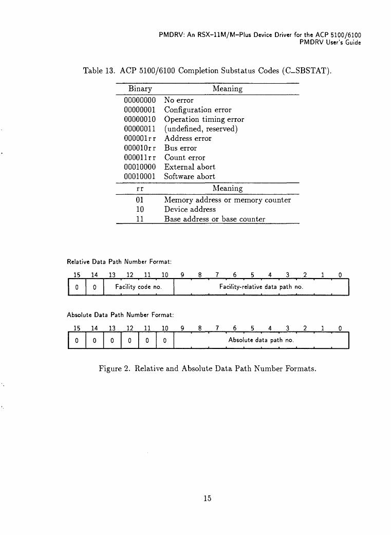
B.I EXECUTIVE PREREQUISITES
PMDRV is a loadable driver with a loadable data base a resident version of the driver cannot be generated from the sources supplied. The driver assembly code checks for the Executive conditional assembly symbol L$$DRV and generates an assembly-time error if it is not defined. PMDRV always declares itself loadable by defining LD$PM=0.
Since loadable driver support also requires a mapped system, PMDRV does not support unmapped systems. (There is no additional test for the Executive conditional assembly symbol M$$MGE.) However, PMDRV is conditionalized to support both 18-bit and 22-bit RSX-11M systems; RSX-llM-Plus systems are always 22-bit systems.
PMDRV makes extensive use of the PDP-11 Extended Instruction Set (EIS). The driver assembly code checks for the Executive conditional assembly symbol R$$EIS and gener ates an assembly-time error if it is not defined.
The top of the interrupt vector area in the Executive must be set high enough to allow for two device interrupt vectors at the selected base interrupt vector address. The default base interrupt vector addresses in Table B-l cannot be used if the standard top address is used (400g). If the base interrupt vector address exceeds the top of the Executive interrupt vector area, the controller on-line request will fail (either the RSX-11M MCR LOA command or the RSX-llM-Plus MCR CON ONLINE command).
B.2 DEVICE DATA BASE
The AGP 5100/6100 hardware CSR address is selected using on-board switch packs and must match the CSR address in the device data base. The hardware base interrupt vector address is programmable and is loaded using the interrupt vector address in the device data base.
Several conditionals are provided for tailoring the device data base (see Table B-l). These are typically defined in an assembly prefix file, PMPre.mac, not in the driver source files, PMDrv.mac and PMTab.mac. For a single ACP 5100 or ACP 6100 at the standard factory address, PMPre .mac can be eliminated or simply be an empty file. If multiple devices are required, or if the default values given in Table B-l are unsuitable, PMPre.mac must be edited to supply the desired values.
B-l
21

PMDRV: An RSX-llM/M-Plus Device Driver for the ACP 5100/6100 PMDRV Installation
Table B-l. Default ACP 5100/6100 Device Configuration Values.
Symbol Meaning
P$$M11 The number of ACP 5100 and/or ACP 6100 communications interfaces gener ated into the system (named PMO:, PM1:, etc.).Default: P$$M11*1.
PMcCSR The CSR address for controller c, where c is A for the first controller, B for the second controller, etc. (must be a multiple of 408). (The DEC standard controller alphabet is A, B, C, D, E, F, H, J, K, L, M, N, P, R, S, T.) Each ACP 5100/6100 occupies 16 words on the I/O page, starting with the CSR.
Default: PMACSR=167000, PMBCSR=167040, PMCCSR=167100, PMDCSR=167140.
PMcVEC The base interrupt vector address for controller c (must be a multiple of 10s). Each ACP 5100/6100 uses two consecutive interrupt vectors.
Default: PMAVEC=400, PMBVEO410, PMCVEC=420, PMDVEO430.
B.3 MCR COMMANDS
To assemble and link PMDRV (assuming, for example, the source code is placed in SY:[100,10]), enter the following MCR commands:
>SET /NONAMED>SET /UIC=[100,10]>LBR ACPDef/cr:24.:::Macro=ACPDef>MAC PMDrv,PMDrv/-sp=LB:[1,1]ExeMC/ml,[11,10]RSXMC/pa:1,-->SY:[lOO,10]ACPDef/ml,PMPre,PMDrv>MAC PMTab,PMTab/-sp=LB:[l,1]ExeMC/ml,[11,10]RSXMC/pa:1,-->SY:[lOO,10]ACPDef/ml,PMPre,PMTab>TKBTKB>PMDrv/-mm/-hd,PMDrv/-sp,PMDrv=PMDrv,PMTabTKB>LB:[1,54]RSX11M.stb/ss,[1,l]ExeLib/lbTKB>/Enter Options:TKB>Stack=0TKB>Par=DRVPAR:120000:20000TKB>//
To load PMDRV into the DRVPAR partition, enter the following MCR commands:
>SET /UIC=[1,54]>PIP LB:/nv=[100,10]PMDrv.tsk,PMDrv.stb>LOA PM:
B-222

PMDRV: An RSX-llM/M-Plus Device Driver for the ACP 5100/6100PMDRV Installation
On RSX-llM-Plus, the devices must be brought on line with the following MCR com mands:
>CON ONLINE PMA,PMO: >CON ONLINE PMB.PM1:
The ACP 5100/6100 takes about 20 seconds to complete its internal self-tests following the RSX-11M MCR LOA command or the RSX-llM-Plus MCR CON ONLINE command.
B-3
23

PMDRV: An RSX-llM/M-Plus Device Driver for the ACP 5100/6100 PMDRV Installation
B-4
24

APPENDIX C
PMDRV VARIANTS
C.I ALTERNATE DEVICE SUPPORT
PMDRV supports three variants of the AGP 5100/6100: the ACP 5100L/6100L, the ACP 5250/6250, and the ACP 5000/6000 with firmware loader (see Table C-1). These devices may be supported by the driver in addition to, or instead of, the ACP 5100/6100. By default, if none of the conditionals in Table C-1 are defined, the driver supports only the ACP 5100/6100. If any other devices are supported, then support for the ACP 5100/6100 is not automatically included, and must be manually selected for support, if required.
Table C-1. PMDRV Optional Device Support.
SjTnbol Meaning
PM$100 PMDRV support for the ACP 5100/6100.Default: If no other devices are supported, PM$100=0;
otherwise, PM$100 is undefined.
PM$STR PMDRV support for the ACP 5100L/6100L.
Default: PM$STR is undefined.
PM$250 PMDRV support for the ACP 5250/6250.
Default: PM$250 is undefined.
PM$LDR PMDRV support for the ACP 5000/6000 with firmware loader. Default: PM$LDR is undefined.
N$$DPN Number of data paths per controller (3-1024). (Each data path requires 5 words of internal driver storage for each controller. Since the driver code and internal data structures must fit within one APR (4K words), the practical limit is substantially less than 1024 if P$$M11 is greater than 1.)Default: If PM$STR is defined, N$$DPN=10.; otherwise, N$$DPN=3.
N$$FAC Number of facilities per controller (3-15). (Each facility requires 2 words of internal driver storage for each controller.)
Default: If PM$STR is defined, N$$FAC=9.; otherwise, N$$FAC=3.
C-125

PMDRV: An RSX-llM/M-Plus Device Driver for the ACP 5100/6100 PMDRV Variants
C.I.I ACP 5100L/6100L Support
If PM$STR is defined, the default maximum number of facilities (N$$FAC) is 9 instead of 3, and the default maximum number of data paths (N$$DPN) is 10 instead of 3.
C.1.2 ACP 5250/6250 Support
If PM$250 is defined, the HDLC facility is permanently assigned to all legal data paths (0-65) on an ACP 5250/6250.
C.I.3 ACP 5000/6000 with Firware Loader Support
If PM$LDR is denned, the additional privileged device-specific I/O functions in Table C-2 are valid for an ACP 5000/6000 with firmware loader.
Table C-2. Device-Specific ACP 5000/6000 Firmware Loader I/O Functions.
__________Format______________________Function___________QIOSC IO.WPDIIQ.UMD,... ,<stadd, Write microprocessor memory
size, ,addlo,addhi ,regbuf > QIO$C IO.RPDJIQ.UMD, ... ,<stadd, Read microprocessor memory
size, ,addlo,addhi ,regbuf > QIOSC IO.BLS1IQ.UMD, ..., Start microprocessor
<,,,addlo,addhi,regbuf> _____
staddThe starting address of the microprocessor memory data buffer.
sizeThe data buffer size, in bytes (must be greater than 0).
addloThe low-order 16 bits of the 24-bit ACP 5000/6000 microprocessor memory address.
addhiThe high-order 8 bits of the 24-bit ACP 5000/6000 microprocessor memory address.
regbufA 40 word diagnostic register buffer.
The device-specific ACP 5000/6000 firmware loader I/O functions are described in greater detail below.
C.1.3.1 IO.RPDUQ. UMD and 10. WPDUQ. UMD. The IO.RPD and IO.WPD diagnos tic I/O functions read from and write to the microprocessor memory of an ACP 5000/6000 with firmware loader. The driver supplies a 30 second timeout for each transfer.
The data buffer is specified in the first I/O parameter, which must be in writeable memory (even if it is used exclusively for writing), and must be on a word boundary. The number
C-2
26

PMDRV: An RSX-llM/M-Plus Device Driver for the ACP 5100/6100PMDRV Variants
of bytes is in the second I/O parameter, which must be even and greater than zero. The memory data must be in the format expected by the ACP 5000/6000 firmware loader.
The 24-bit microprocessor memory address is provided in the fourth and fifth I/O pa rameter words. The high-order 8 bits of the 32-bit address are ignored, but should be specified as zero for compatibility with any future expansion to 32-bit addressing.
The IQ.UMD user-mode diagnostic I/O subfunction bit is required, and is the only I/O subfunction bit allowed. The sixth I/O parameter must contain the address of a 40 word register buffer in writeable memory. (This is required by RSX, but is not used by the driver.)
C.1.3.2 IO.BLSUQ.UMD. The IO.BLS diagnostic I/O function instructs the firmware loader in an ACP 5000/6000 to start execution of the front-end microprocessor at the address specified in the fourth and fifth I/O parameters. A 30 second timeout (the warm-start timeout count) is used. Following a succesful initialization interrupt, the unit on-line routine in the driver is called to attempt to recognize the new application.
The IQ.UMD user-mode diagnostic I/O subfunction bit is required, and is the only I/O subfunction bit allowed. The sixth I/O parameter must contain the address of a 40 word register buffer in writeable memory. (This is required by RSX, but is not used by the driver.)
C.I.4 Loadable Applications Support
PMDRV contains a table of supported devices, labeled DEVTBL (shown below), which contains an extra entry, labeled $DT6XX, when PM$LDR is defined.
DEVTBL: ; Supported System IDs table
.Macro ACPDev DType,PermDP
.Byte DType,PermDP-PRMTBL
.EndM ACPDev
.Ilf DF PM$100, ACPDev DT$610,PRM100 ; ACP 5100/6100
.Ilf DF PM$250, ACPDev DT$625,PRM250 ; ACP 5250/6250.If DF PM$LDRACPDev DT$6LD,PRMLDR ; ACP 5000/6000 w/loader
; Slot for downloaded System ID: $DT6XX::ACPDev -1,PRMLDR ; ACP 5XXX/6XXX
.EndC ; DF PM$LDR
.Word 0 ; End of table
To prepare the driver for a new application, $DT6XX may be patched to define a new System ID and optionally point to a new permanent facility data paths table. When the application is committed to ROM, DEVTBL should be modified to define it permanently, using the ACPDev macro.
C-3
27

PMDRV: An RSX-llM/M-Plus Device Driver for the ACP 5100/6100 PMDRV Variants
For example, the following task builder option will define a new System ID, numbered 9i6, that uses the same data path allocation scheme as the ACP 5100/6100:
TKB>GblPat=PMDRV:$DT6XX:11
C.2 MISCELLANEOUS CONDITIONALS
Three other conditionals are used in the driver: CLASS, DEBUG, and MBXOPT.
The CLASS conditional is intended to configure the driver to support a class (i.e., facility) driver interface in addition to the port driver interface, supplied by PMDRV. However, this has not yet been implemented, so CLASS should not be defined.
The DEBUG conditional adds additional sanity checks and console output to the driver for use during debugging. DEBUG should not defined for normal driver operation.
The MBXOPT conditional causes the interrupt "a" fork routine to poll all three handshaking mailboxes until no more work can be performed. It then waits for another interrupt "a". Also, code is added to the interrupt "a" service routine to eliminate the transition to fork level if no mailboxes require service (z'.e., the work has already been done). If MBXOPT is undefined, the driver behaves exactly as the ACC PMDRIVER for VAX/VMS, which polls the three mailboxes once per interrupt. MBXOPT is permanently defined in the driver source code for optimal performance.
C-4
28