Embed Size (px)
Citation preview


©PMA Prozeß- und Maschinen-Automation GmbH. Printed in GermanyAll rights reserved. No part of this document may be
reproduced or published in any form or by any means without prior written permissionby the copyright owner.
A publication of PMA Prozeß- und Maschinen-Automation GmbH
Subject to change without notice.
PMA Prozeß- und Maschinen-Automation GmbHP.O. Box 31 02 29
D 34058 KasselGermany
Restriction to warranty:
No warranty for the perfect correctness of the contents is taken, since errors cannot be avoidedcompletely despite utmost care. User feedback is always appreciated.

KS 800 CAN-Interface
Contents
1 Introduction . . . . . . . . . . . . . . . . . . . . . . . . . . . . . . . . . . . . . . . . . . . . . . . . . . . . . . 5
2 Service data objects . . . . . . . . . . . . . . . . . . . . . . . . . . . . . . . . . . . . . . . . . . . . . . . . 7
3 Process data objects . . . . . . . . . . . . . . . . . . . . . . . . . . . . . . . . . . . . . . . . . . . . . . . 93.1 Information Record (send PDO from KS800): . . . . . . . . . . . . . . . . . . . . . . . . . 103.2 Control Record (KS800 receive PDO): . . . . . . . . . . . . . . . . . . . . . . . . . . . . . . 113.3 PDO transfer behaviour . . . . . . . . . . . . . . . . . . . . . . . . . . . . . . . . . . . . . . . . . 12
3.3.1 Asynchronous send PDO . . . . . . . . . . . . . . . . . . . . . . . . . . . . . . . . . . . 123.3.2 Synchronous send PDO . . . . . . . . . . . . . . . . . . . . . . . . . . . . . . . . . . . . 133.3.3 Asynchronous receive PDO . . . . . . . . . . . . . . . . . . . . . . . . . . . . . . . . . 133.3.4 Synchronous receive PDO . . . . . . . . . . . . . . . . . . . . . . . . . . . . . . . . . . 14
4 OP mode / pre-OP mode . . . . . . . . . . . . . . . . . . . . . . . . . . . . . . . . . . . . . . . . . . . . 15
5 SYNC . . . . . . . . . . . . . . . . . . . . . . . . . . . . . . . . . . . . . . . . . . . . . . . . . . . . . . . . . . 16
6 Nodeguarding / Lifeguarding . . . . . . . . . . . . . . . . . . . . . . . . . . . . . . . . . . . . . . . . 17
7 LMT services . . . . . . . . . . . . . . . . . . . . . . . . . . . . . . . . . . . . . . . . . . . . . . . . . . . . 187.1 Switch Mode Services . . . . . . . . . . . . . . . . . . . . . . . . . . . . . . . . . . . . . . . . . . 18
7.1.1 Switch Mode Global . . . . . . . . . . . . . . . . . . . . . . . . . . . . . . . . . . . . . . . . 187.1.2 Switch Mode Selective . . . . . . . . . . . . . . . . . . . . . . . . . . . . . . . . . . . . . . 18
7.2 Configuration Services . . . . . . . . . . . . . . . . . . . . . . . . . . . . . . . . . . . . . . . . . . 197.2.1 Configure Module ID . . . . . . . . . . . . . . . . . . . . . . . . . . . . . . . . . . . . . . . 197.2.2 Configure Bit Timing . . . . . . . . . . . . . . . . . . . . . . . . . . . . . . . . . . . . . . . 19
7.3 Inquire LMT Address . . . . . . . . . . . . . . . . . . . . . . . . . . . . . . . . . . . . . . . . . . . 207.3.1 Inquire Manufacturer Name . . . . . . . . . . . . . . . . . . . . . . . . . . . . . . . . . . 207.3.2 Inquire Product Name . . . . . . . . . . . . . . . . . . . . . . . . . . . . . . . . . . . . . . 207.3.3 Inquire Serial Number . . . . . . . . . . . . . . . . . . . . . . . . . . . . . . . . . . . . . . 217.3.4 Serial Number Format . . . . . . . . . . . . . . . . . . . . . . . . . . . . . . . . . . . . . . 21
7.4 Identification Services . . . . . . . . . . . . . . . . . . . . . . . . . . . . . . . . . . . . . . . . . . 217.4.1 LMT Identify Remote Slaves . . . . . . . . . . . . . . . . . . . . . . . . . . . . . . . . . 217.4.2 LMT Identify Slave . . . . . . . . . . . . . . . . . . . . . . . . . . . . . . . . . . . . . . . . 22
7.5 Manufacturer-specific LMT services . . . . . . . . . . . . . . . . . . . . . . . . . . . . . . . . 227.6 Inquire Node-ID . . . . . . . . . . . . . . . . . . . . . . . . . . . . . . . . . . . . . . . . . . . . . . . 22
7.6.1 Configure Module-ID . . . . . . . . . . . . . . . . . . . . . . . . . . . . . . . . . . . . . . . 237.6.2 Configure Bit Timing . . . . . . . . . . . . . . . . . . . . . . . . . . . . . . . . . . . . . . . 237.6.3 Inquire Bit Timing . . . . . . . . . . . . . . . . . . . . . . . . . . . . . . . . . . . . . . . . . 24
8 Object directory . . . . . . . . . . . . . . . . . . . . . . . . . . . . . . . . . . . . . . . . . . . . . . . . . . 258.1 Survey of object directory - manufacturer-specific section . . . . . . . . . . . . . . . . . 25
9 Configuration and parameter setting via the CAN bus . . . . . . . . . . . . . . . . . . . . . 369.1 Configuring KS 800 via CAN bus interface . . . . . . . . . . . . . . . . . . . . . . . . . . . 36
9.1.1 Saving the non-volatile set-point . . . . . . . . . . . . . . . . . . . . . . . . . . . . . . . 369.2 Data plausibility check during transmission . . . . . . . . . . . . . . . . . . . . . . . . . . . 379.3 Table of allocation of firmware version, operating version, series number and
engineering tool . . . . . . . . . . . . . . . . . . . . . . . . . . . . . . . . . . . . . . . . . . . . . . . 379.4 Order of data for configuration and parameter setting . . . . . . . . . . . . . . . . . . . . 38
9499 040 49511 3

KS 800 CAN-Interface
10 Application example . . . . . . . . . . . . . . . . . . . . . . . . . . . . . . . . . . . . . . . . . . . . . . . 4010.1 KS800 standard settings . . . . . . . . . . . . . . . . . . . . . . . . . . . . . . . . . . . . . . . . 4010.2 Adjusting a heating/cooling controller . . . . . . . . . . . . . . . . . . . . . . . . . . . . . . . 4010.3 Adjusting a H/C controller and activating the self-tuning . . . . . . . . . . . . . . . . . . 41
11 CAN Physical Layer . . . . . . . . . . . . . . . . . . . . . . . . . . . . . . . . . . . . . . . . . . . . . . . 4311.1 ISO 11898-2 nodes: . . . . . . . . . . . . . . . . . . . . . . . . . . . . . . . . . . . . . . . . . . . . 4311.2 Bit rates and bus lengths: . . . . . . . . . . . . . . . . . . . . . . . . . . . . . . . . . . . . . . . . 4411.3 Practical bus lengths . . . . . . . . . . . . . . . . . . . . . . . . . . . . . . . . . . . . . . . . . . . 4411.4 Cable parameters . . . . . . . . . . . . . . . . . . . . . . . . . . . . . . . . . . . . . . . . . . . . . 45
4 9499 040 49511

KS 800 CAN-Interface
1 Introduction
Controller KS800 is provided with a CAN interface, via which all data (parameter and configu-ration data) required for operation can be sent to the controller. A master (PC or PLC) can alsoread all process data via this interface.According to "CANopen", the accesses are grouped into SDOs (Service Data Objects) and PDOs(Process Data Objects). SDOs are provided for configuration and parameter setting of bus unitsand PDOs are provided for the normal operating values.
KS800 operation at the CAN bus:
After KS800 start-up, the unit is in the "Pre Operational Mode". Communication via the CANinterface is possible by means of SDOs. After bus and controller configuration, the master mustput KS800 to "Operational Mode" (NMT Start), in which using PDOs is also possible.How to use PDOs must be configured in advance. There are "asynchronous" and "synchronousPDOs". Asynchronous PDOs are sent with status changes such as out-of-tolerance band, sensorbreak or similar events. Synchronous PDOs are sent on request by the master. For this purpose,the master sends a SYNC frame. In the KS800 default setting, asynchronous PDOs are enabled(for details, see Process-Data-Objects).
Implemented in KS800 are based on the "CANopen Communication Profile for Industrial Sys-tems" (CiA Draft Standard 301). The functionality corresponds to the "Minimum Thecommunication services Capability Device" with "Predefined Master/Slave Connection Set",completed by "LMT-services", however, without "Time Stamp" and "Store Paramter" objects.
Type Address (dec.) Address (hex.)
NMT_Commands 0 0x0
SYNC 128 0x80
LMT-RX 2021 0x7E5
LMT-TX 2020 0x7E4
EMERGENCY 128 + NodeID *) 0x80 + NodeID *)
PDO1-TX 384 + NodeID *) 0x180 + NodeID *)
PDO1-RX 512 + NodeID *) 0x200 + NodeID *)
PDO2-TX 640 + NodeID *) 0x280 + NodeID *)
PDO2-RX 768 + NodeID *) 0x300 + NodeID *)
SDO-TX 1408 + NodeID *) 0x580 + NodeID *)
SDO-RX 1536 + NodeID *) 0x600 + NodeID *)
NODE_GUARD 1769 + NodeID *) 0x6E0 + NodeID *) **)
*) NodeID range within 1 ...127**)KS 800 default does not correpond to 301-standard
9499 040 49511 5

KS 800 CAN-Interface
Network management:
For communication monitoring, KS800 offers the possibility of "nodeguarding", which enables themaster to detect whether a KS800 is connected to the bus and whether the communication tothe controller is ensured.Adjusting the node ID (node address) and CAN-baudrate required for identification of a CAN unitis done using the KS800 Engineering Tool via the diagnosis interface.Adjusting via CAN-Bus is also possible (see chapter 7).
6 9499 040 49511

KS 800 CAN-Interface
2 Service data objects
An SDO is logically determined to exactly two partners - 1 master and 1 slave. Simultaneousaccess to the KS800 by two different masters is not possible, since only one SDO channel isavailable for "tx" and for "rx".Max. 4 bytes of usable data can be transmitted by means of SDOs. The remaining 4 bytes areused as follows:
1 byte for the command: transmission mode2 bytes for the index: object identification
(e.g. 0x2213 for Wvol - see object directory)1 byte for the subindex: channel number
An example of an SDO data frame for reading and for writing is given below.
Example 1. A master sends a set-point to a KS800 with node address 4:
The message structure is as follows:
⇒ COB_ID = SDO at node 4 = 0x600 + 4 = 0x604⇒ CMD = write access = 0x2B = 0x2B⇒ INDEX = set-point = 0x2213 = 0x2213⇒ SUBINDEX = e.g. controller 1 = 01 = 0x01⇒ WERT = 30,0°C *) = 300 *) = 0x12C
*) Fixedpoint1: 1 fixed digit behind the decimal point.
8 data bytes
COB-ID LEN Cmd Index Sub. Data
Enquiry:(Master)
0x604 0x08 0x2B 0x130x22
0x01 0x2C 0x02 0x00 0x00
Reply:(KS800)
0x584 0x08 0x60 0x130x22
0x01 0x00 0x00 0x00 0x00
9499 040 49511 7

KS 800 CAN-Interface
Example 2. A master reads a process value from a KS800 with node address 2:
The message structure is as follows:
⇒ COB_ID = SDO at node 2 = 0x600 + 2 = 0x602⇒ CMD = read access = 0x40 = 0x40⇒ INDEX = process value = 0x2202 = 0x2202⇒ SUBINDEX = e.g. controller 3 = 03 = 0x03
8 data bytes
COB-ID LEN Cmd Index Sub. Data
Enquiry:(Master)
0x602 0x08 0x40 0x020x22
0x03 0x00 0x00 0x00 0x00
Reply:(KS800)
0x582 0x08 0x4B 0x020x22
0x03 0xFA 0x00 0x00 0x00
⇒ WERT = 0x00FA = 250 = 25,0°C
By means of the SDOs, controller configuration and parameter setting can be adjusted via indi-vidual accesses to all parameters (see object directory). However, addressing of all operatingdata, which are normally transmitted via PDOs, can also be done via SDOs.
8 9499 040 49511

KS 800 CAN-Interface
3 Process data objects
Max. 4 bytes of usable data can be transmitted between two partners by means of SDOs. Theremaining 4 bytes are used for the command, the index and the subindex. With one PDO, howe-ver, max. 8 bytes of usable data can be transmitted. Two send and two receive PDOs, which canbe defined as "synchronous PDOs" or as "asynchronous PDOs" via configuration, are supportedby KS800. For instance, the data transfer via the PDOs is purposeful, when controller processvalues and status values must be sent to the master dependent of e.g. error messages (change-of-state). In this case, asynchronous PDOs, which will be sent to the master automatically whenthe event occurs on the controller are used. Another example would be cyclic enquiry of processvalues by an operating unit. In this case, KS800 can send PDOs by synchronization with a clockfrequency (SYNC-EVENT).As opposed to SDOs, PDOs are always non-acknowledged services. They can be received byseveral units. As already mentioned above, this does not apply to SDOs.
In the KS800 default configuration, one asynchronous send and receive PDO with the followingidentifiers are enabled:
COB-ID of the asynchronous receive PDO: 0x200 + node IDCOB-ID of the asynchronous send PDO: 0x180 + node ID
PDO reconfiguration is possible by means of SDO accesses to the following indexes:
default default COB-ID
Index 1400: first receive PDO sync./disabled 300
Index 1401: second receive PDO async./enabled 200
Index 1800: first send PDO sync./disabled 280
Index 1801: second send PDO async./enabled 180
Configuration of the message identifier (COB-ID) as well as PD0 enabling and disabling are doneunder subindex 1.
COB-ID (low byte) data[ 1]COB-ID (high byte) data[ 2]Enable data[ 4] (0x00 = enabled, 0x80 = disabled)
Transfer type configuration is under subindex 2.
Transfer type data[ 1] (0x01...0x0F = synch, 0xFF = async)
The PDO data contents are described in the following section.
9499 040 49511 9

KS 800 CAN-Interface
3.1 Information Record (send PDO from KS800):
The structure of the Information Record is:
Index Subindex Field Data Type
42 0 number of supported entries in the record unsigned8
1 channel number unsigned8
2 Xeff FixedPoint1
3 device status information unsigned8
4 channel status information unsigned16
5 Ypid FixedPoint1
In detail, a send PDO from KS800 contains the following data:
channel → data[ 0]Xeff → data[ 1, 2]
low byte data[ 1]high byte data[ 2]
Controller status information data[ 3]
Bit 0*) - offline[0], online [1]Bit 1*) - DO1...12 failBit 2*) - DO13...16 failBit 3*) - heating current short circuit is configuredBit 4 - "Input state" signalling,Bit 5 - as an input, otherwise "0".Bit 6 - Bit 7 - Does not generate an asynchronous PDo trigger!
Channel status information (bit=1 in case of alarm): data[ 4, 5]
Bit 0*) - HH alarm data[ 4]Bit 1*) - H alarmBit 2*) - L alarmBit 3*) - LL alarmBit 4*) - Sensor fail alarmBit 5*) - Heating current alarmBit 6*) - Leakage current alarmBit 7*) - DO_x alarmBit 8*) - W2 active data[ 5]Bit 9*) - Wint activeBit 10*) - Wanfahr activeBit 11*) - Self-tuning activeBit 12*) - Self-tuning errorBit 13*) - Controller A/MBit 14*) - Controller switched off (coff)
Ypid: data [6, 7]low Byte *) - data [6]high Byte *) - data [7]
*) A change generates an asynchronous PDO event.
10 9499 040 49511
KS 800 CAN-Interface
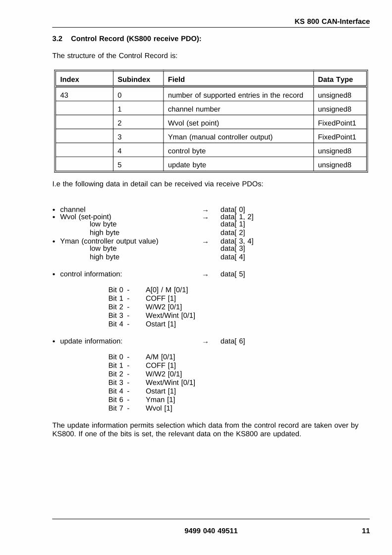
3.2 Control Record (KS800 receive PDO):
The structure of the Control Record is:
Index Subindex Field Data Type
43 0 number of supported entries in the record unsigned8
1 channel number unsigned8
2 Wvol (set point) FixedPoint1
3 Yman (manual controller output) FixedPoint1
4 control byte unsigned8
5 update byte unsigned8
I.e the following data in detail can be received via receive PDOs:
channel → data[ 0]Wvol (set-point) → data[ 1, 2]
low byte data[ 1]high byte data[ 2]
Yman (controller output value) → data[ 3, 4]low byte data[ 3]high byte data[ 4]
control information: → data[ 5]
Bit 0 - A[0] / M [0/1]Bit 1 - COFF [1]Bit 2 - W/W2 [0/1]Bit 3 - Wext/Wint [0/1]Bit 4 - Ostart [1]
update information: → data[ 6]
Bit 0 - A/M [0/1]Bit 1 - COFF [1]Bit 2 - W/W2 [0/1]Bit 3 - Wext/Wint [0/1]Bit 4 - Ostart [1]Bit 6 - Yman [1]Bit 7 - Wvol [1]
The update information permits selection which data from the control record are taken over byKS800. If one of the bits is set, the relevant data on the KS800 are updated.
9499 040 49511 11
KS 800 CAN-Interface
3.3 PDO transfer behaviour
3.3.1 Asynchronous send PDO
When a PDO is configured as an asynchronous PDO, a PDO is sent with status-information-resp. Ypid- changes of a channel. The message order is: checking whether sending is necessarystarts with the first channel. If a change-of-state is detected (flag fSendEvent set), a PDO isgenerated, sent and the flag is reset. After successful sending, the next channel is handled. Ifthe two send PDOs are configured as asynchronous PDOs, two channels are checked and sentsimultaneously.
Example:Channel 1: fSendEvent = TRUE
→ send PDO for channel 1Channel 2: fSendEvent = FALSEChannel 3: fSendEvent = TRUE
→ send PDO for channel 3Channel 4: fSendEvent = FALSEChannel 5: fSendEvent = FALSEChannel 6: fSendEvent = FALSEChannel 7: fSendEvent = TRUE
→ send PDO for channel 7Channel 8: fSendEvent = FALSEChannel 1: fSendEvent = FALSE
An asynchronous PDO is always sent by KS800 with status bit change-of-state or changing ofYpid. In default configuration, the message sent by KS800 is:
Message from KS800 (ASYNC-PDO):
8 data bytes
COB-ID LEN Channel Xeff Dev. st. Channel st. Ypid
0x180 +node 8 0x05 0xBC 0x02 0x00 0x00 0x42 0xF4 0x01
⇒ Xeff = 0x02BC = 700 = 70,0°C⇒ Device Status = 0x00 = keine Fehler⇒ Channel Status = 0x4200 = Coff = 1, Wint = 1⇒ Ypid = 0x01F4 = 500 = 50%
12 9499 040 49511

KS 800 CAN-Interface
3.3.2 Synchronous send PDO
The master sends SYNC pulses for actual process value refreshment. The number of Sync mes-sages after which must react can be configured by the master. The default setting is "1". (seeTransfer-Type, chapter 3 Process-Data-Objekts)
During synchronous operation, a channel starting with the first one is sent after each Sync mes-sage (if transfer-type = 1 ). Subsequently, all further channels are sent successively. After thelast channel, a new cycle is started at the first one. If the two send PDOs are configured assynchronous PDOs, two channels are transmitted simultaneously. The following diagram explainsthe interactions of Sync message and PDOs.
3.3.3 Asynchronous receive PDO
When an asynchronous PDO is received, the contained data are passed on to the controllermodule with the next kommunucation -modul-cyclus. The data are written into the buffer accor-ding to channel number. Thereby, the fReceived flag is set. This signals that new data for thecontroller are ready for receiving. The fReceived flag is reset by the controller.
Caution: When passing new data to the controller, the communication module does not check,if the controller has already taken over the data received last.(Scanning rate must be taken into account.) i.e. PDOs can be overwritten, earlierinformation will be lost.
9499 040 49511 13

KS 800 CAN-Interface
3.3.4 Synchronous receive PDO
When receiving a synchronous PDO, the data remain in the Rx buffer at first (CAN-controller)without being transmitted to the controller. For this, the received flag for the relevant channel isset. This signals that new data for the controller are ready for receiving. The fReceived flag isreset by the controller. The interaction of Sync message and synchronous PDOs is shown in thefollowing diagram.
Caution: When receiving another synchronous PDO before the next Sync message, the PDOreceived last is transmitted to the controller. i.e. PDOs can be overwritten, earlierinformation will be lost.
Explanation of the diagram:At time S.n, the data of PDOs which were received between S.n-1 and S.n are passed onto the controller. These are the data for channel 1, 4 and 6.
At time S.n+1, the data of PDOs which were received between S.n and S.n+1 are passedon to the controller. These are the PDOs for channel 3, 6 and 8.
14 9499 040 49511

KS 800 CAN-Interface
4 OP mode / pre-OP mode
After starting the CAN network, controller KS800 is in the pre-OP mode. I.e. it can be addressedonly via SDOs. When setting KS800 to the OP mode, communication via the enabled PDOs isalso possible. The asynchronous PDOs are enabled after start-up. If necessary, the synchronousPDOs must be enabled via SDO messages.
Setting KS800 to OP mode:
2 data bytes
COB-ID LEN Command Node
0x00 2 0x01 <Number> *)
When selecting node address "0", all controllers in the network are set to the OP mode. Thecontrollers do not send a reply to this message.
Setting KS800 to pre-OP mode:
2 data bytes
COB-ID LEN Command Node
0x00 2 0x80 <Number> *)
When selecting node address "0", all controllers in the network are set to the pre-OP mode. Thecontrollers do not send a reply to this message.
Further NMT (Network-Management) - Commands:
Reset Node:
2 data bytes
COB-ID LEN Command Node
0x00 2 0x81 <Number> *)
Reset Communication:
2 data bytes
COB-ID LEN Command Node
0x00 2 0x82 <Number> *)
*) NodeID-range within 1 ...127
Caution: Reset mode leads to a KS 800 reset, i.e. the controller will be accessible viaCAN-bus again only after several seconds. All Command-Parameters are set to the defaultvalues.
9499 040 49511 15

KS 800 CAN-Interface
5 SYNC
As described above, synchronous PDO data must be read from or written to KS 800 by meansof SYNC pulses. The relevant KS800 controllers must be in OP mode and the SYNC-PDOs mustbe enabled via SDO. For this, object "0x1800" must be set to value "0x280+nodes".A SYNC message is a "broadcast" (message to all units in the network) which is activated by themaster as follows:
0 data bytes
COB-ID LEN
0x80 2
Reply from KS800:
e.g. following PDO
8 data bytes
COB-ID LEN Channel Xeff Dev. st. Channel st. Ypid
0x80 +node 8 0x05 0x2BC 0x02 0x00 0x00 0x42 0xF4 0x01
⇒ Xeff = 0x0BC = 700 = 700°C⇒ Device Status = 0x00 = kein Fehler⇒ Channel Status = 0x4200 = Coff = 1, Wint = 1⇒ Ypid = 0X01F4 = 500 = 50%
After a new SYNC by the master, the data of the next channel, i.e. channel 6 in this case, aretransmitted, etc. After transmission of the eightth channel, restart is at channel 1. With severalKS800 units in a network, the data of the relevant channel are sent by each controller per SYNCevent. (max. 2 channels, if 2 synchronous PD=s are configured)
*) The COB-ID default value of 0x80 can be changed with object 1005.
16 9499 040 49511

KS 800 CAN-Interface
6 Nodeguarding / Lifeguarding
"Nodeguarding" can be used by a master for testing cyclically, if the relevant slave (KS800) isstill in the network.The "guard time * life time" can be used to determine at which intervals the master must activatethe nodeguard message (timeout for the master).With a "guard time * life time" = "0", no timeout for the master is determined, i.e. the master neednot use a fixed time interval. If a "guard time * life time" is defined and data are not read fromKS800 at this interval, KS800 may return from the OP-mode to the pre-OP mode. In this case,no PDOs can be transmitted any more.Generally, KS800 replies to a "nodeguard" by "toggling" the most significant bit:
Node-Guarding Identifier → Objekt 100E Default: 6E0 + node ID
In OP-mode, KS800 replies: 0x05 → 0x85 → 0x05 → 0x85 → ...In pre-OP mode, KS800 replies: 0x7F → 0xFF → 0x7F → 0xFF → ...
Nodeguard message (RTR):
0 data bytes
COB-ID LEN
0x6E0 + node 0
Reply from KS800 (pre-OP mode):
1 data bytes
COB-ID LEN Answer
0x6E0 +node0x6E0 +node0x6E0 +node
111
0x7F0x7F0x7F
Reply from KS800 (OP mode):
1 data bytes
COB-ID LEN Answer
0x6E0 +node0x6E0 +node0x6E0 +Node
111
0x050x050x05
Notes: The default value for the node guarding identifier remains 0x6E0+ node-ID (not com-patible with DS301 version 3.0, but downward-compatible). The value can be readand changed via object 0x100E.
9499 040 49511 17

KS 800 CAN-Interface
7 LMT services (CMS standard and extensions)
The LMT services according to CiA/DS205 version 1.1 are available. Restrictions, or specialextensions are given in the following service descriptions. The relevant COB IDs are 2021 (ma-ster ⇒ slave), or 2020 (slave ⇒ master), whereby KS800 is slave.
7.1 Switch Mode Services
7.1.1 Switch Mode Global
M ⇒ S0 1 2 3 4 5 6 7
cs = 04 mode r r r r r r
cs LMT command specifiermode 0: switches to operation mode
1: switches to configuration moder reserved
7.1.2 Switch Mode Selective
M ⇒ S0 1 2 3 4 5 6 7
cs = 01 m1 m2 m3 m4 m5 m6 m7
0 1 2 3 4 5 6 7cs = 02 p1 p2 p3 p4 p5 p6 p7
0 1 2 3 4 5 6 7cs = 02 s1 s2 s3 s4 s5 s6 s7
cs LMT command specifierm1..7 manufacturer name part of LMT addressp1..7 product name part of LMT addresss1..7 serial number part of LMT address
18 9499 040 49511

KS 800 CAN-Interface
7.2 Configuration Services
Configure NMT Address comprises services Configure Module ID and Configure Module Name.Service Configure Module Name is not supported. A relevant request provides error code: 255and specific_error_code: 01 (service not supported).
7.2.1 Configure Module ID
M ⇒ S0 1 2 3 4 5 6 7
cs = 17 MId r r r r r rS ⇒ M
0 1 2 3 4 5 6 7cs = 17 error
codespecerror
r r r r r
cs LMT command specifierMId new module_id to be configurederror_code 0: successful
1..254: reserved255: implementation specific error
specific_error only valid if error_code equal to 2553: MId out of range4: command execution error
r reserved
7.2.2 Configure Bit Timing
M ⇒ S0 1 2 3 4 5 6 7
cs = 19 tableselector
tableindex
r r r r r
S ⇒ M0 1 2 3 4 5 6 7
cs = 19 errorcode
specerror
r r r r r
cs LMT command specifiertable_selector 0: standard CiA bit timing tabletable_index 0: 1 Mbit
1: 800 kbit2: 500 kbit3: 250 kbit4: 125 kbit5: 50 kbit6: 20 kbit7: 10 kbit
error_code 0: successful1: bit timing not supported2..254: reserved255: implementation specific error
specific_error only valid if error_code equal to 2553: value out of range4: command execution error
r reserved
9499 040 49511 19

KS 800 CAN-Interface
Service Activate Bit Timing is not supported (unconfirmed service !), activation is via a reset (seeaddress/BR-switch for the 3 reset possibilities).
Service Store Configuration is not supported. A relevant request provides error_code: 01 (servicenot supported).
7.3 Inquire LMT Address
Inquire LMT address comprises the following 3 services:
7.3.1 Inquire Manufacturer Name
M ⇒ S0 1 2 3 4 5 6 7
cs = 36 r r r r r r rS ⇒ M
0 1 2 3 4 5 6 7cs = 36 m1 m2 m3 m4 m5 m6 m7
cs LMT command specifierm1..m7 manufacturer name of the module (if m1 is a valid alpha-num character).
If m1 is 255, m2 contains error_code and m3 optional error reason.(provides the "company name" (PMA))
7.3.2 Inquire Product Name
M ⇒ S0 1 2 3 4 5 6 7
cs = 37 r r r r r r r
S ⇒ M0 1 2 3 4 5 6 7
cs = 37 p1 p2 p3 p4 p5 p6 p7
cs LMT command specifierp1..p7 product name of the module (if p1 is a valid alpha-num character).
If p1 is 255, p2 contains error_code and p3 optional error reason.(provides the "system name" (Popen))
r reserved
20 9499 040 49511

KS 800 CAN-Interface
7.3.3 Inquire Serial Number
M ⇒ S0 1 2 3 4 5 6 7
cs = 38 r r r r r r r
S ⇒ M0 1 2 3 4 5 6 7
cs = 38 s1 s2 s3 s4 s5 s6 s7
cs LMT command specifiers1..s7 serial number of the module (if s1 is a valid BCD-pair).
If s1 is 255, s2 contains error_code and s3 optional error reason.(provides the instrument code number)
r reserved
7.3.4 Serial Number Format (14 BCD-digit ⇒ 7 byte)
0 1 2 3 4 5 6 7 8 9 10 11 12 130 0 m1 m2 m3 m4 c1 c2 c3 c4 c5 c6 c7 c8
m1..m4 FabMonth, month of production in coded formc1..c8 FabCount, "unique" count number, must be defined only once
7.4 Identification Services
7.4.1 LMT Identify Remote Slaves
M ⇒ S0 1 2 3 4 5 6 7
cs = 05 manu-fact.
name
M ⇒ S0 1 2 3 4 5 6 7
cs = 06 product nameM ⇒ S
0 1 2 3 4 5 6 7cs = 07 serial number low
M ⇒ S0 1 2 3 4 5 6 7
cs = 08 serial number high
cs LMT command specifiermanufact._name manufacturer name part of LMT addressproduct_name product name partserial_number_low lower boundary of requested rangeserial_number_high higher boundary
("boundaries" are contained in the interval)
9499 040 49511 21

KS 800 CAN-Interface
7.4.2 LMT Identify Slave
S ⇒ M0 1 2 3 4 5 6 7
cs = 09 r r r r r r r
cs LMT command specifierr reserved
Notes: With several instruments connected to the bus, there may be problems, especiallyframe loss! (due to the number of simultaneously replying units with identical frames)
7.5 Manufacturer-specific LMT services
Service Activate Bit Timing (cs = 131) is not supported (see also Std. service with the samename).
7.6 Inquire Node-ID
M ⇒ S0 1 2 3 4 5 6 7
cs = 128 CAN r r r r r rS ⇒ M
0 1 2 3 4 5 6 7cs = 128 error
codespecerror
NodeID
r r r r
cs LMT command specifierCAN number of CAN-controller (must be 0)error_code 0: successful
1..254: reserved255: implementation specific error
specific_error only valid if error_code equal 2556: illegal CAN-controller selected
Node ID module Node ID
22 9499 040 49511

KS 800 CAN-Interface
7.6.1 Configure Module-ID
M ⇒ S0 1 2 3 4 5 6 7
cs = 129 MId CAN r r r r rS ⇒ M
0 1 2 3 4 5 6 7cs = 129 error
codespecerror
r r r r r
cs LMT command specifierCAN number of CAN-controller (must be 0)Mid new module_id to be configurederror_code 0: successful
1..254: reserved255: implementation specific error
specific_error only valid if error_code equal to2553: Mid out of range4: command execution error6: illegal CAN-controller selected
r reserved
7.6.2 Configure Bit Timing
M ⇒ S0 1 2 3 4 5 6 7
cs = 130 tableselector
tableindex
CAN r r r r
S ⇒ M0 1 2 3 4 5 6 7
cs = 130 errorcode
specerror
r r r r r
cs LMT command specifierCAN number of CAN-controller (must be 0)table_selector 0: standard CiA bit timing tabletable_index 0: 1 Mbit
1: 500 kbit2: 250 kbit3: 125 kbit4: -5: 50 kbit6: 20 kbit7: 10 kbit8: 800 kbit
error_code 0: successful1: bit timing not supported2..254: reserved255: implementation specific error
specific_error only valid if error_code equal to 2553: value out of range4: command execution error6: illegal CAN-controller selected
r reserved
9499 040 49511 23

KS 800 CAN-Interface
7.6.3 Inquire Bit Timing
M ⇒ S0 1 2 3 4 5 6 7
cs = 132 r r r r r r rS ⇒ M
0 1 2 3 4 5 6 7cs = 132 error
codespecerror
tableselector
tableindex
CAN BTR0 BTR1
cs LMT command specifierCAN number of CAN-controller (always 0)BTR0/BTR1 bit timing register 0 and 1 of CAN-controllertable_selector standard CiA bit timing table (always 0)table_index 0: 1 Mbit
1: 500 kbit2: 250 kbit3: 125 kbit4: -5: 50 kbit6: 20 kbit7: 10 kbit8: 800 kbit
error_code 0: successful1: bit timing not supported2..254: reserved255: implementation specific error
specific_error only valid if error_code equal to 255r reserved
24 9499 040 49511

KS 800 CAN-Interface
8 Object directory
The manufacturer-specific, list-oriented entries in the object directory are explained below.
8.1 Survey of object directory - manufacturer-specific section
Note: The overall object directory is designed dually (from index 2001; from index 3001) topermit equal objectswith different data types.
Index table structure:
The index is a 4-digit number in hexadecimal notation with the following structure.
MSB LSB
Format Function block Function Parameter no.
2=Fixed Point Format 0=Device current number current number3=Float Format 1=Input
2=Controller3=Alarm
Configuration mode:
Configuration changes such as output allocations or span end values are not taken over on-line.For changing these parameters, KS800 must be switched to configuration mode. Mode switch-over is via SDO access.
Index 2008 (OPMod): value = 0 configuration modevalue = 1 normal mode
For changing data identified with rw*) in the object directory, OPMod must be set to 0. Thenew parameters are taken over when changing the OPMod back from 0 -> 1 subsequently.
Used data-formats:
Unsigned8: 8-bit-value, without sign, range 0 ... 256Unsigned16: 16-bit-value, without sign, range 0 ... 65535Fixedpoint1: 16 bit-integer-value with 1 fixed digit behind the decimal point, within-32767 ... +32767. When interpreting these values, the last digit is considered as a digit behindthe decimal point, e.g. 12345 means 1234,5 (°C), or 873 are 87,3 (%).
9499 040 49511 25

KS 800 CAN-Interface
Column "as from firmware": C = This datum exists already from operating version 1, however, it wassubject to change (extension) in the course of development.N = This datum was added as from the specified operating version.
Index(hex)
Object(symbolicname)
Name Type Attri-bute
asfromfirm-ware
FB unit
Process data fct.no.0
2001 VAR Status 1Unit-State1 Unsigned8 ro 1.0
2002 VAR Basic hardware options HWbas Unsigned16 ro 1.0
2003 VAR SW options SWopt Unsigned16 ro 1.0
2004 VAR SW code no. SWCode Unsigned16 ro 1.0
2005 VAR SW version SWVersion Unsigned16 ro 1.0
2006 VAR Operating version OPVers Unsigned16 ro 1.0
2007 VAR EEPROM version EEPVers Unsigned16 ro 1.0
2008 VAR Configuration mode selection OPMod Unsigned8 rw 1.0
2009 VAR Self-tuning stop/start of all group controllersOStartg
Unsigned8 rw 1.0
200A VAR Local data change flag reset Unsigned8 rw 1.0
Parameter and configuration data fct. no. 0
200B VAR Baudrate COM 1 C900 Unsigned16 rw* 1.0
200C VAR Controller address Adr1 Unsigned16 rw* 1.0
200D VAR Mains frequency 50/60 Unsigned8 rw* 1.0C
200E VAR Baudrate COM 2 C900 (CAN baudrate) Unsigned16 rw* 1.0
200F VAR Controller address Adr2 (CAN Node ID) Unsigned16 rw* 1.0
2010 VAR Releasing the cooling function for Water Co-oling
FixedPoint1 rw* 2.0
2011 VAR Heating-current reset / quicktest Unsigned8 rw 4.0
Process data Fct. no. 2
2020 VAR Status alarm outputs State_alarm_out Unsigned8 ro 1.0
2021 VAR Status dig. inputs/outputs State_dio Unsigned8 ro 1.0
Parameter and configuration data fct.no. 2
2022 VAR Main config. C500 Unsigned16 rw* 1.0
2023 VAR Main config. C530 Unsigned16 rw* 1.0
2024 VAR Allocation HC/leakage current C151 Unsigned16 rw* 1.0C
2025 VAR Heating current cycle Hccycl Unsigned16 rw* 1.0
2026 VAR Span end for HC input HC 100 FixedPoint1 rw* 1.0
26 9499 040 49511

KS 800 CAN-Interface
2027 VAR Forced dig. output OUT1...OUT8 Unsigned8 rw* 2.1
2028 VAR Forced dig. output OUT9...OUT16 Unsigned8 rw* 2.1
2029 VAR Forced dig. output OUT17...OUT19 Unsigned8 rw* seename
FB input
Process data fct. no. 0
2100 ARRAY Signal input fail Input_X_Failed Unsigned8 ro 1.0
2101 ARRAY Main variable x1 FixedPoint1 ro 1.0
2102 ARRAY Raw measurement value before meas.val.corr.INP1
FixedPoint1 ro 1.0
Parameter and configuration data fct. no. 1
2110 ARRAY Measurement value correction X1 input X1in FixedPoint1 rw 1.0
2111 ARRAY Measurement value correction X1 output X1out FixedPoint1 rw 1.0
2112 ARRAY Measurement value correction X2 X2in FixedPoint1 rw 1.0
2113 ARRAY Measurement value correction X2 X2out FixedPoint1 rw 1.0
2114 ARRAY Sensor type (T,H) C200 Unsigned16 rw* 1.0
2115 ARRAY Fail: sensor break (T) C205 Unsigned16 rw* 1.0
2116 ARRAY Phys. value at 0% X0 FixedPoint1 rw* 1.0
2117 ARRAY Phys. value at 100% X100 FixedPoint1 rw* 1.0
2118 ARRAY Substitute value at sensor fail XFail FixedPoint1 rw* 1.0
2119 ARRAY Filter time const. meas. value processing Tfm FixedPoint1 rw* 1.0
211A ARRAY Reference temperature Tkref FixedPoint1 rw* 1.0
211B ARRAY Signal allocation dig. signals C190 Unsigned16 rw* 1.0
FB analog out
Process data fct. no. 0
2130 ARRAY Forced analog output AOUT1...AOUT16 FixedPoint1 rw 3.0
2140 ARRAY Xo FixedPoint1 rw* 3.0
2141 ARRAY X100 FixedPoint1 rw* 3.0
2142 ARRAY Mode/Scr A-Out C540 Unsigned16 rw* 3.0
FB controller
Process data fct. no. 0
2200 ARRAY Status 1 Unsigned8 ro 1.0
2201 ARRAY Eff. set-point Weff FixedPoint1 ro 1.0
2202 ARRAY Eff. process value Xeff FixedPoint1 ro 1.0
2203 ARRAY Effective correcting variable Ypid FixedPoint1 ro 1.0
2204 ARRAY Control deviation xw FixedPoint1 ro 1.0
2205 ARRAY Automatic/manual switch-over Unsigned8 rw 1.0
9499 040 49511 27

KS 800 CAN-Interface
2206 ARRAY Controller self-tuning start OStart Unsigned8 rw 1.0
2207 ARRAY Switch-over Wext/Wint We/i Unsigned8 rw 1.0
2208 ARRAY Switch-over W/W2 w/W2 Unsigned8 rw 1.0
2209 ARRAY Controller on/off Coff Unsigned8 rw 1.0
Parameter and configuration data fct. no. 0
220A ARRAY Main configuration 1, control C100 Unsigned16 rw* 1.0
220B ARRAY Main configuration 2, control C101 Unsigned16 rw* 1.0
220C ARRAY Configuration tuning C700 Unsigned16 rw* 1.0
220D ARRAY Signal allocation anal. C180 Unsigned16 rw* 1.0C
Process data Fct. no. 1
2210 ARRAY Set-point-status WState Unsigned8 ro 1.0
2211 ARRAY Effective internal set-point Wint FixedPoint1 ro 1.0
2212 ARRAY Int. set-point, non-volatile Wnvol FixedPoint1 rw 1.0
2213 ARRAY Int. set-point, volatile Wvol FixedPoint1 rw 1.0
Parameter and configuration data fct. no. 1
2214 ARRAY Lower set-point limit for Weff W0 FixedPoint1 rw 1.0
2215 ARRAY Upper set-point limit for Weff W100 FixedPoint1 rw 1.0
2216 ARRAY Additional set-point W2 FixedPoint1 rw 1.0
2217 ARRAY Set-point gradient plus Grw+ FixedPoint1 rw 1.0
2218 ARRAY Set-point gradient minus Grw- FixedPoint1 rw 1.0
2219 ARRAY Set-point gradient W2 Grw2 FixedPoint1 rw 1.0
221A ARRAY Loop-alarm on/off C102 Unsigned 16 rw* 4.0N
Parameter and configuration data fct. no. 2
2220 ARRAY Adaption-mode C710 Unsigned16 rw* 4.0N
Parameter and configuration data fct. no. 3
2230 ARRAY Neutral zone Xsh FixedPoint1 rw 1.0C
2231 ARRAY Min. pulse length Tpuls FixedPoint1 rw 1.0C
2232 ARRAY Actuator response time Tm FixedPoint1 rw 1.0
2233 ARRAY Signaller switching difference Xsd1 FixedPoint1 rw 1.0
2234 ARRAY Trigger point separation additional contact LW FixedPoint1 rw 1.0
2235 ARRAY Switching difference additional contact Xsd2 FixedPoint1 rw 1.0
2236 ARRAY Neutral zone Xsh1 FixedPoint1 rw 1.0
2237 ARRAY Neutral zone Xsh2 FixedPoint1 rw 1.0
28 9499 040 49511

KS 800 CAN-Interface
Process data fct. no. 4
2240 ARRAY Difference correcting variable dYman FixedPoint1 rw 1.0
2241 ARRAY Absolute correcting variable Yman FixedPoint1 rw 1.0
2242 ARRAY Increm. adjustment of correcting variable Yinc Unsigned8 rw 1.0
2243 ARRAY Decrem. adjustment of correcting variable Ydec Unsigned8 rw 1.0
2244 ARRAY Speed for increm. and decrem. adjustment ofcorrecting variable Ygrw_is
Unsigned8 rw 1.0
Parameter and configuration data fct. no. 4
2245 ARRAY Min. output limiting Ymin FixedPoint1 rw 1.0
2246 ARRAY Max. output limiting Ymax FixedPoint1 rw 1.0
2247 ARRAY Working point for correcting variable Y0 FixedPoint1 rw 1.0
2248 ARRAY Max. mean value of correcting variable Yhm FixedPoint1 rw 1.0
2249 ARRAY Limit for mean value formation LYh FixedPoint1 rw 1.0
Process data fct. no. 5
2250 ARRAY Status Tuning State_Tune1 Unsigned8 ro 1.0
2251 ARRAY Eff. additional parameter number ParNeff Unsigned8 ro 1.0
2252 ARRAY Additional parameter number effective ParNr Unsigned8 rw 1.0
2253 ARRAY Delay time heating Tu1 FixedPoint1 ro 1.0
2254 ARRAY Rate of increase heating Vmax1 FixedPoint1 ro 1.0
2255 ARRAY Process gain heating Kp1 FixedPoint1 ro 1.0
2256 ARRAY Error code of controller self-tuning heatingMSG1
Unsigned8 ro 1.0
2257 ARRAY Delay time cooling Tu2 FixedPoint1 ro 1.0
2258 ARRAY Rate of increase cooling Vmax FixedPoint1 ro 1.0
2259 ARRAY Process gain cooling Kp2 FixedPoint1 ro 1.0
225A ARRAY Error code of controller self-tuning coolingMSG2
Unsigned8 ro 1.0
Parameter and configuration data fct. no. 5
225B ARRAY Correcting variable during process at restYOptm
FixedPoint1 rw 1.0
225C ARRAY Step height with identification dYopt FixedPoint1 rw 1.0
225D ARRAY Parameter set to be optimized POpt Unsigned8 rw 1.0
225E ARRAY Hysteresis with parameter switch-over OXsd FixedPoint1 rw 1.0
225F ARRAY Trigger point 1 Trig1 FixedPoint1 rw 1.0
Parameter and configuration data fct. no. 6
2260 ARRAY Proportional band 1 Xp1_1 FixedPoint1 rw 1.0
2261 ARRAY Integral time 1 Tn1_1 FixedPoint1 rw 1.0
2262 ARRAY Derivative time 1 Tv1_1 FixedPoint1 rw 1.0
9499 040 49511 29

KS 800 CAN-Interface
2263 ARRAY Min. cycle time 1 T1_1 FixedPoint1 rw 1.0
2264 ARRAY Proportional band 2 Xp2_1 FixedPoint1 rw 1.0
2265 ARRAY Integral time 2 Tn2_1 FixedPoint1 rw 1.0
2266 ARRAY Derivative time 2 Tv2_1 FixedPoint1 rw 1.0
2267 ARRAY Min. cycle time 2 T2_1 FixedPoint1 rw 1.0
Parameter and configuration data fct. no. 7
2270 ARRAY Proportional band 1 Xp1_2 FixedPoint1 rw 1.0
2271 ARRAY Integral time 1 Tn1_2 FixedPoint1 rw 1.0
2272 ARRAY Derivative time 1 Tv1_2 FixedPoint1 rw 1.0
2273 ARRAY Min. cycle time 1 T1_2 FixedPoint1 rw 1.0
2274 ARRAY Proportional band 2 Xp2_2 FixedPoint1 rw 1.0
2275 ARRAY Integral time 2 Tn2_2 FixedPoint1 rw 1.0
2276 ARRAY Derivative time 2 Tv2_2 FixedPoint1 rw 1.0
2277 ARRAY Min. cycle time 2 T2_2 FixedPoint1 rw 1.0
Parameter and configuration data fct. no. 10
22A0 ARRAY Max. output value Ya FixedPoint1 rw 1.0
22A1 ARRAY Start-up set-point Wa FixedPoint1 rw 1.0
22A2 ARRAY Start-up holding time TPa FixedPoint1 rw 1.0
FB alarm
Process data fct. no. 0
2300 ARRAY Alarm status 1 Status_AL1 Unsigned8 ro 1.0
2301 ARRAY Heating current alarm Status_AL2 Unsigned8 ro 1.0
2302 ARRAY Heating current measurement value HC FixedPoint1 ro 1.0
Parameter and configuration data fct. no. 0
2303 ARRAY Low limit alarm LimL FixedPoint1 rw 1.0
2304 ARRAY High limit alarm LimH FixedPoint1 rw 1.0
2305 ARRAY Switching difference high/low alarm xsd_2 FixedPoint1 rw 1.0
2306 ARRAY Low low limit alarm LimLL FixedPoint1 rw 1.0
2307 ARRAY High high limit alarm LimHH FixedPoint1 rw 1.0
2308 ARRAY Heating current limit value LimHC FixedPoint1 rw 1.0
2309 ARRAY Src: signal source (T,H) C600Fnc: function (Z)
Unsigned16 rw* 1.0
230A ARRAY Alarm target C601 Unsigned16 rw* 1.0
230B ARRAY Alarmsource/-function L, C602 Unsigned16 rw* 3.0N
230C ARRAY Alarmsource/-function H, C603 Unsigned16 rw* 3.0N
230D ARRAY Alarmsource/-function HH, C604 Unsigned16 rw* 3.0N
30 9499 040 49511

KS 800 CAN-Interface
Column "as from firmware": C = This datum exists already from operating version 1, however, it wassubject to change (extension) in the course of development.N = This datum was added as from the specified operating version.
Index(hex)
Object(symbolicname)
Name Type Attri-bute
asfromfirm-ware
FB unit
Process data fct.no.0
3001 VAR Status 1Unit-State1 Unsigned8 ro 1.0
3002 VAR Basic hardware options HWbas Unsigned16 ro 1.0
3003 VAR SW options SWopt Unsigned16 ro 1.0
3004 VAR SW code no. SWCode Unsigned16 ro 1.0
3005 VAR SW version SWVersion Unsigned16 ro 1.0
3006 VAR Operating version OPVers Unsigned16 ro 1.0
3007 VAR EEPROM version EEPVers Unsigned16 ro 1.0
3008 VAR Configuration mode selection OPMod Unsigned8 rw 1.0
3009 VAR Self-tuning stop/start of all group controllersOStartg
Unsigned8 rw 1.0
300A VAR Local data change flag reset Unsigned8 rw 1.0
Parameter and configuration data fct. no. 0
300B VAR Baudrate COM 1 C900 Unsigned16 rw* 1.0
300C VAR Controller address Adr1 Unsigned16 rw* 1.0
300D VAR Mains frequency 50/60 Unsigned8 rw* 1.0C
300E VAR Baudrate COM 2 C900 (CAN baudrate) Unsigned16 rw* 1.0
300F VAR Controller address Adr2 (CAN Node ID) Unsigned16 rw* 1.0
3010 VAR Releasing the cooling function for Water Co-oling
FixedPoint1 rw* 2.0
3011 VAR Heating-current reset / quicktest Unsigned8 rw 4.0
Process data Fct. no. 2
3020 VAR Status alarm outputs State_alarm_out Unsigned8 ro 1.0
3021 VAR Status dig. inputs/outputs State_dio Unsigned8 ro 1.0
Parameter and configuration data fct.no. 2
3022 VAR Main config. C500 Unsigned16 rw* 1.0
3023 VAR Main config. C530 Unsigned16 rw* 1.0
3024 VAR Allocation HC/leakage current C151 Unsigned16 rw* 1.0C
3025 VAR Heating current cycle Hccycl Unsigned16 rw* 1.0
3026 VAR Span end for HC input HC 100 FixedPoint1 rw* 1.0
3027 VAR Forced dig. output OUT1...OUT8 Unsigned8 rw* 2.1
9499 040 49511 31
KS 800 CAN-Interface
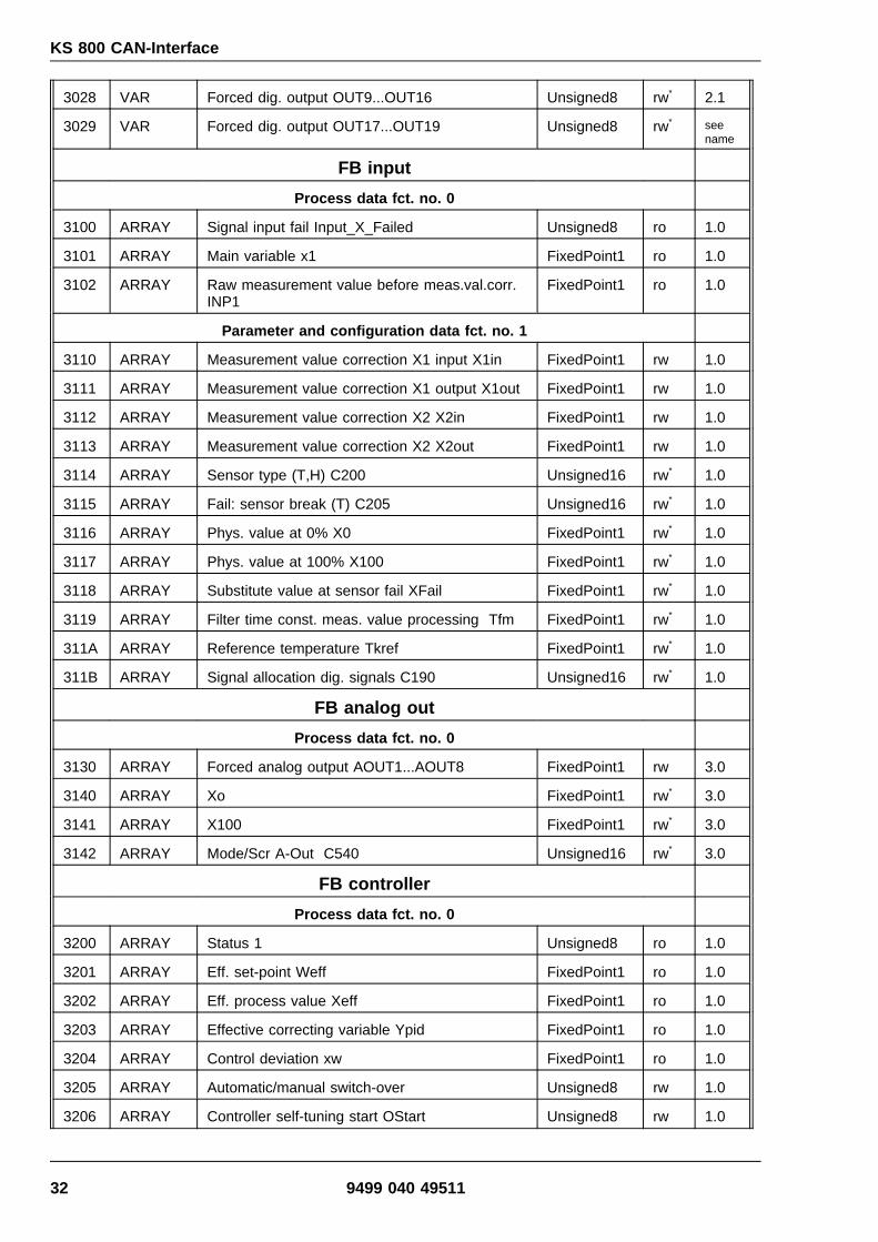
3028 VAR Forced dig. output OUT9...OUT16 Unsigned8 rw* 2.1
3029 VAR Forced dig. output OUT17...OUT19 Unsigned8 rw* seename
FB input
Process data fct. no. 0
3100 ARRAY Signal input fail Input_X_Failed Unsigned8 ro 1.0
3101 ARRAY Main variable x1 FixedPoint1 ro 1.0
3102 ARRAY Raw measurement value before meas.val.corr.INP1
FixedPoint1 ro 1.0
Parameter and configuration data fct. no. 1
3110 ARRAY Measurement value correction X1 input X1in FixedPoint1 rw 1.0
3111 ARRAY Measurement value correction X1 output X1out FixedPoint1 rw 1.0
3112 ARRAY Measurement value correction X2 X2in FixedPoint1 rw 1.0
3113 ARRAY Measurement value correction X2 X2out FixedPoint1 rw 1.0
3114 ARRAY Sensor type (T,H) C200 Unsigned16 rw* 1.0
3115 ARRAY Fail: sensor break (T) C205 Unsigned16 rw* 1.0
3116 ARRAY Phys. value at 0% X0 FixedPoint1 rw* 1.0
3117 ARRAY Phys. value at 100% X100 FixedPoint1 rw* 1.0
3118 ARRAY Substitute value at sensor fail XFail FixedPoint1 rw* 1.0
3119 ARRAY Filter time const. meas. value processing Tfm FixedPoint1 rw* 1.0
311A ARRAY Reference temperature Tkref FixedPoint1 rw* 1.0
311B ARRAY Signal allocation dig. signals C190 Unsigned16 rw* 1.0
FB analog out
Process data fct. no. 0
3130 ARRAY Forced analog output AOUT1...AOUT8 FixedPoint1 rw 3.0
3140 ARRAY Xo FixedPoint1 rw* 3.0
3141 ARRAY X100 FixedPoint1 rw* 3.0
3142 ARRAY Mode/Scr A-Out C540 Unsigned16 rw* 3.0
FB controller
Process data fct. no. 0
3200 ARRAY Status 1 Unsigned8 ro 1.0
3201 ARRAY Eff. set-point Weff FixedPoint1 ro 1.0
3202 ARRAY Eff. process value Xeff FixedPoint1 ro 1.0
3203 ARRAY Effective correcting variable Ypid FixedPoint1 ro 1.0
3204 ARRAY Control deviation xw FixedPoint1 ro 1.0
3205 ARRAY Automatic/manual switch-over Unsigned8 rw 1.0
3206 ARRAY Controller self-tuning start OStart Unsigned8 rw 1.0
32 9499 040 49511

KS 800 CAN-Interface
3207 ARRAY Switch-over Wext/Wint We/i Unsigned8 rw 1.0
3208 ARRAY Switch-over W/W2 w/W2 Unsigned8 rw 1.0
3209 ARRAY Controller on/off Coff Unsigned8 rw 1.0
Parameter and configuration data fct. no. 0
320A ARRAY Main configuration 1, control C100 Unsigned16 rw* 1.0
320B ARRAY Main configuration 2, control C101 Unsigned16 rw* 1.0
320C ARRAY Configuration tuning C700 Unsigned16 rw* 1.0
320D ARRAY Signal allocation anal. C180 Unsigned16 rw* 1.0C
Process data Fct. no. 1
3210 ARRAY Set-point-status WState Unsigned8 ro 1.0
3211 ARRAY Effective internal set-point Wint FixedPoint1 ro 1.0
3212 ARRAY Int. set-point, non-volatile Wnvol FixedPoint1 rw 1.0
3213 ARRAY Int. set-point, volatile Wvol FixedPoint1 rw 1.0
Parameter and configuration data fct. no. 1
3214 ARRAY Lower set-point limit for Weff W0 FixedPoint1 rw 1.0
3215 ARRAY Upper set-point limit for Weff W100 FixedPoint1 rw 1.0
3216 ARRAY Additional set-point W2 FixedPoint1 rw 1.0
3217 ARRAY Set-point gradient plus Grw+ FixedPoint1 rw 1.0
3218 ARRAY Set-point gradient minus Grw- FixedPoint1 rw 1.0
3219 ARRAY Set-point gradient W2 Grw2 FixedPoint1 rw 1.0
321A ARRAY Loop-alarm on/off C102 Unsigned 16 rw* 4.0N
Parameter and configuration data fct. no. 2
3220 ARRAY Adaption-mode C710 Unsigned16 rw* 4.0N
Parameter and configuration data fct. no. 3
3230 ARRAY Neutral zone Xsh FixedPoint1 rw 1.0C
3231 ARRAY Min. pulse length Tpuls FixedPoint1 rw 1.0C
3232 ARRAY Actuator response time Tm FixedPoint1 rw 1.0
3233 ARRAY Signaller switching difference Xsd1 FixedPoint1 rw 1.0
3234 ARRAY Trigger point separation additional contact LW FixedPoint1 rw 1.0
3235 ARRAY Switching difference additional contact Xsd2 FixedPoint1 rw 1.0
3236 ARRAY Neutral zone Xsh1 FixedPoint1 rw 1.0
3237 ARRAY Neutral zone Xsh2 FixedPoint1 rw 1.0
9499 040 49511 33

KS 800 CAN-Interface
Process data fct. no. 4
3240 ARRAY Difference correcting variable dYman FixedPoint1 rw 1.0
3241 ARRAY Absolute correcting variable Yman FixedPoint1 rw 1.0
3242 ARRAY Increm. adjustment of correcting variable Yinc Unsigned8 rw 1.0
3243 ARRAY Decrem. adjustment of correcting variable Ydec Unsigned8 rw 1.0
3244 ARRAY Speed for increm. and decrem. adjustment ofcorrecting variable Ygrw_is
Unsigned8 rw 1.0
Parameter and configuration data fct. no. 4
3245 ARRAY Min. output limiting Ymin FixedPoint1 rw 1.0
3246 ARRAY Max. output limiting Ymax FixedPoint1 rw 1.0
3247 ARRAY Working point for correcting variable Y0 FixedPoint1 rw 1.0
3248 ARRAY Max. mean value of correcting variable Yhm FixedPoint1 rw 1.0
3249 ARRAY Limit for mean value formation LYh FixedPoint1 rw 1.0
Process data fct. no. 5
3250 ARRAY Status Tuning State_Tune1 Unsigned8 ro 1.0
3251 ARRAY Eff. additional parameter number ParNeff Unsigned8 ro 1.0
3252 ARRAY Additional parameter number effective ParNr Unsigned8 rw 1.0
3253 ARRAY Delay time heating Tu1 FixedPoint1 ro 1.0
3254 ARRAY Rate of increase heating Vmax1 FixedPoint1 ro 1.0
3255 ARRAY Process gain heating Kp1 FixedPoint1 ro 1.0
3256 ARRAY Error code of controller self-tuning heatingMSG1
Unsigned8 ro 1.0
3257 ARRAY Delay time cooling Tu2 FixedPoint1 ro 1.0
3258 ARRAY Rate of increase cooling Vmax FixedPoint1 ro 1.0
3259 ARRAY Process gain cooling Kp2 FixedPoint1 ro 1.0
325A ARRAY Error code of controller self-tuning coolingMSG2
Unsigned8 ro 1.0
Parameter and configuration data fct. no. 5
325B ARRAY Correcting variable during process at restYOptm
FixedPoint1 rw 1.0
325C ARRAY Step height with identification dYopt FixedPoint1 rw 1.0
325D ARRAY Parameter set to be optimized POpt Unsigned8 rw 1.0
325E ARRAY Hysteresis with parameter switch-over OXsd FixedPoint1 rw 1.0
325F ARRAY Trigger point 1 Trig1 FixedPoint1 rw 1.0
Parameter and configuration data fct. no. 6
3260 ARRAY Proportional band 1 Xp1_1 FixedPoint1 rw 1.0
3261 ARRAY Integral time 1 Tn1_1 FixedPoint1 rw 1.0
3262 ARRAY Derivative time 1 Tv1_1 FixedPoint1 rw 1.0
34 9499 040 49511

KS 800 CAN-Interface
3263 ARRAY Min. cycle time 1 T1_1 FixedPoint1 rw 1.0
3264 ARRAY Proportional band 2 Xp2_1 FixedPoint1 rw 1.0
3265 ARRAY Integral time 2 Tn2_1 FixedPoint1 rw 1.0
3266 ARRAY Derivative time 2 Tv2_1 FixedPoint1 rw 1.0
3267 ARRAY Min. cycle time 2 T2_1 FixedPoint1 rw 1.0
Parameter and configuration data fct. no. 7
3270 ARRAY Proportional band 1 Xp1_2 FixedPoint1 rw 1.0
3271 ARRAY Integral time 1 Tn1_2 FixedPoint1 rw 1.0
3272 ARRAY Derivative time 1 Tv1_2 FixedPoint1 rw 1.0
3273 ARRAY Min. cycle time 1 T1_2 FixedPoint1 rw 1.0
3274 ARRAY Proportional band 2 Xp2_2 FixedPoint1 rw 1.0
3275 ARRAY Integral time 2 Tn2_2 FixedPoint1 rw 1.0
3276 ARRAY Derivative time 2 Tv2_2 FixedPoint1 rw 1.0
3277 ARRAY Min. cycle time 2 T2_2 FixedPoint1 rw 1.0
Parameter and configuration data fct. no. 10
32A0 ARRAY Max. output value Ya FixedPoint1 rw 1.0
32A1 ARRAY Start-up set-point Wa FixedPoint1 rw 1.0
32A2 ARRAY Start-up holding time TPa FixedPoint1 rw 1.0
FB alarm
Process data fct. no. 0
3300 ARRAY Alarm status 1 Status_AL1 Unsigned8 ro 1.0
3301 ARRAY Heating current alarm Status_AL2 Unsigned8 ro 1.0
3302 ARRAY Heating current measurement value HC FixedPoint1 ro 1.0
Parameter and configuration data fct. no. 0
3303 ARRAY Low limit alarm LimL FixedPoint1 rw 1.0
3304 ARRAY High limit alarm LimH FixedPoint1 rw 1.0
3305 ARRAY Switching difference high/low alarm xsd_2 FixedPoint1 rw 1.0
3306 ARRAY Low low limit alarm LimLL FixedPoint1 rw 1.0
3307 ARRAY High high limit alarm LimHH FixedPoint1 rw 1.0
3308 ARRAY Heating current limit value LimHC FixedPoint1 rw 1.0
3309 ARRAY Src: signal source (T,H) C600Fnc: function (Z)
Unsigned16 rw* 1.0
330A ARRAY Alarm target C601 Unsigned16 rw* 1.0
330B ARRAY Alarmsource/-function L, C602 Unsigned16 rw* 3.0N
330C ARRAY Alarmsource/-function H, C603 Unsigned16 rw* 3.0N
330D ARRAY Alarmsource/-function HH, C604 Unsigned16 rw* 3.0N
9499 040 49511 35

KS 800 CAN-Interface
9 Configuration and parameter setting via the CAN bus
The following versions are of importance only in case of KS 800 configuration and parametersetting via the CAN bus. Normally, the engineering tool is used for this purpose, whereby mutualconfiguration data checking and correct order of data during download are already taken intoaccount.
The order in which the data must be sent to KS 800 for correct configuration and parametersetting is specified in the list given below. This ensures that values which affect each othermutually get a suitable content, e.g. a change of the sensor type resets the setpoint limits W0and W100 to the default values (physical measurement limits of the relevant sensor type). Bysetting set-point limits W0 = 50°C and W100 = 350°C first followed by determination of thermo-couple type K, the set-point limits would be reset to W0 = 0°C and W100 = 1350°C.
Moreover, note that a defined order of transmission must be met with parameters par_w0 andpar_w100, or par_ymin and par_ymax., because these two value pairs are checked for plausibili-ty. The higher value must always be sent first.
If values are set to par_w0 = 100°C and par_w100 = 150°C (set-point adjustment limit between100 and 150°C) and must be changed into par_w0 = 160°C, or par_w100 = 200°C, the datacannot be sent in the order specified below (par_w0 at first followed by par_w100), because thenew lower set-point limit of 160°C is higher than the old upper limit (150°C). In this case, in-crease the new upper limit (par_w100) to 200°C first and change the lower limit to the new valuesubsequently.
9.1 Configuring KS 800 via CAN bus interface:
The specifications described in paragraphs 9.1 to 9.3 need not be taken into account when usingthe engineering tool, because they are taken into account automatically, or in the menus.
1. Switch the instrument to off-line2. Send the configuration data (in correct order)3. Switch the instrument to on-line (the channels operate with the old parameter values)4. Send parameter data (they are taken over during operation)
9.1.1 Saving the non-volatile set-point
Two set-point saving methods can be used by KS 800:
1: The volatile set-point is saved in RAM. The controller uses the value saved in this memoryduring normal control operation.
2: The non-volatile set-point is saved in EEPROM. This set-point is used as "start set-point" afterinitialization (power on, or new configuration) by the controllers. It is copied into the RAM andused as "working" set-point, until the RAM set-point is overwritten by a PLC.
When changing the non-volatile set-point (EEPROM) in the course of reconfiguration, writing intoEEPROM (saving) is done only "at the relevant controller’s turn". This can take max. 2instrument cycles (~1,2s). During the time from the end of writing into RAM until restarting theinstrument, the RAM data are used. Before saving the data in EEPROM, the instrument must notbe switched to "on-line", because some new data may be still unsaved in EEPROM, i.e. the old(set-) values are used again after reinitialization, or after restart.
36 9499 040 49511

KS 800 CAN-Interface
9.2 Data plausibility check during transmission
Caution!
The configuration data are not checked by the instrument. (This check is done only in the engi-neering tool.)
The parameter data are checked for their limits.
9.3 Table of allocation of firmware version, operating version, series number and en-gineering tool.
Date Series-number
Firmwareversion
Operat.version
E-Tool-version
3.8.97 8330 1.0 1 1.0
10.9.97 8334 1.1 1 1.1
28.10.97 8335 1.2 1 1.1
16.12.97 8337 1.3 1 1.1
8.4.98 8341 1.3 1 1.3
11.5.98 8341 1.3 1 1.3
23.9.99 8358 2.0 2 1.4
15.12.99 8361 2.1 2 2.0
7.3.00 8363 2.1 2 3.0SR1
7.3.00 8363 2.2 2 3.0SR1
7.3.00 8364 2.3 3 3.1SR1
10.7.00 8366 2.4 3 3.1SR1
30.3.01 8376 2.5 4 3.2SR3
13.11.01 8384 3.0 5 3.4SR1
19.8.02 8393 4.0 6 1.4SR1(BlueControl)
9499 040 49511 37

KS 800 CAN-Interface
9.4 Order of data for configuration and parameter setting
Column "Function" gives the configuration data the signification of which is described indetail in description manual 9499 040 49218.The digits behind the _(underscore) indicate the digits used in the configuration word.
16 15 14 13 12 11 10 9 8 7 6 5 4 3 2 1
Digit 4 Digit 3 Digit 2 Digit 1
Column "Introduction" gives the operating version in which a configuration datum was introduced.New configuration data are marked with "from OV x" and extensions are marked with "add. fromOV x"
Instrument configuration
CAN Function Introd.Index
200B c900_32 BV 1
200C c901_4321 BV 1
200D c904_4 BV 1c904_1 zus. ab BV ≥ 2c904_32 zus. ab BV ≥ 5
200E c902_32 BV1
200F c903_4321 BV1
2026 c302_4321 BV1
2022 c500_4321 BV 1
2023 c530_432 BV 1
2024 c151_432 BV 1c151_1 zus. ab BV ≥ 3
2025 c150_4321 BV 1
Channel configuration
220A c100_4321 BV 1
220B c101_4321 BV 1
220C c700_4321 BV 1
220D c180_3 BV 1c180_4 zus. ab BV ≥ 5
221A c102_1 ab BV ≥ 6
2220 c710_21 ab BV ≥ 6
2114 c200_432 BV 1
CAN Function Introd.Index
2115 c205_432 BV 1
211B c190_21 BV 1
2116 c201_4321 BV 1
2117 c202_4321 BV 1
2118 c213_4321 BV 1
2119 c214_4321 BV 1
211A c210_4321 BV 1
2309 c600_4321 BV 1
230A c601_4321 BV 1
230B c602_4321 ab BV ≥ 6
230C c603_4321 ab BV ≥ 6
230D c604_4321 ab BV ≥ 6
2140 x0 ab BV ≥ 5
2141 x100 ab BV ≥ 5
2142 c540_31 ab BV ≥ 5
38 9499 040 49511

KS 800 CAN-Interface
Instrument parameters
2010 par_wk_enable ab BV ≥ 2
Channel parameters
2214 par_w0 BV 12215 par_w100 BV 12216 par_w2 BV 12217 par_grwp BV 12218 par_grwm BV 12219 par_grw2 BV 12230 par_xsh BV 1(2230 par_xsh_wk) BV 12231 par_tpuls BV 1(2231 par_tpuls_wk) BV 12232 par_tm BV 12233 par_xsd1 BV 12234 par_lw BV 12235 par_xsd2 BV 12236 par_xsh1 BV 12237 par_xsh2 BV 12245 par_ymin BV 12246 par_ymax BV 12247 par_y0 BV 12248 par_yh BV 12249 par_lyh BV 1225B par_yoptm BV 1225C par_dyopt BV 1225E par_oxsd BV 1225F par_trig1 BV 1225D par_popt BV 12260 par_xp1_0 BV 12261 par_tn1_0 BV 1
2262 par_tv1_0 BV 12263 par_t1_0 BV 12264 par_xp2_0 BV 12265 par_tn2_0 BV 12266 par_tv2_0 BV 12267 par_t2_0 BV 12270 par_xp1_1 BV 12271 par_tn1_1 BV 12272 par_tv1_1 BV 12273 par_t1_1 BV 12274 par_xp2_1 BV 12275 par_tn2_1 BV 12276 par_tv2_1 BV 12277 par_t2_1 BV 122A0 par_ya BV 122A1 par_wa BV 122A2 par_tpa BV 12110 par_x1in BV 12111 par_x1out BV 12112 par_x2in BV 12113 par_x2out BV 12303 par_lim_l BV 12304 par_lim_h BV 12305 par_lim_xsd BV 12306 par_lim_ll BV 12307 par_lim_hh BV 12308 par_lim_hc BV 1
Subsequently, the process datas can beread and written in any order.
When using water cooling, parameters 2230 and 2231 with extension _wk are applicable.
9499 040 49511 39

KS 800 CAN-Interface
10 Application example
10.1 KS800 standard settings
KS800 is factory-set to the default parameters given in the controller description. As a heating/cooling controller is required for the example and a H controller is adjusted as standard, altera-tion via SDOs is required.
10.2 Adjusting a heating/cooling controller
Adjusting a standard controller (only heating) as a heating/cooling controller and reading theprocess value cyclically (via SDOs) are done as described below.
As only channel 1 is required, the subindex for the channel number must be set to "1".
- Set configuration to offline→ Index 0x2008 (OPMod=0)
Reference: process data, individual code 31
- Set main controller configuration C100=0x0300 (H/C controller)→ Index 0x200A
Reference: C100 controller description
- Set main configuration C200=0x2010 (PT100, unit: C)→ Index 0x2114
Reference: C200 - controller description
- Set configuration to online→ Index 0x2008 (OPMod=1)
Reference: process data, individual code 31
- Set set-point Weff→ Index 0x2313 (Weff=250)
- Set controller to AUTO→ Index 0x2205 (A/H=0)
Reference: controller, individual code 33
Loop for actual process values:for(;;){
- Read effective process value channel 1→ Index 0x2202
- wait( 1sec)}
40 9499 040 49511

KS 800 CAN-Interface
10.3 Adjusting a H/C controller and activating the self-tuning
Adjusting a standard controller (H) as a H/C controller via SDOs, starting the self-tuning andreading the actual process values (via SDOs) are done as described below.
As only channel 1 is required, the subindex for the channel number must be set to "1".
- Set configuration to offline→ Index 0x2008 (OPMod=0)
Reference: process data, individual code 31
- Set main controller configuration C100=0x0300 (H/C controller)→ Index 0x200A
Reference: C100 - controller description
- Set main configuration C200=0x2010 (PT100, unit: C)→ Index 0x2114
Reference: C200 - controller description
- Set configuration to online→ Index 0x2008 (OPMod=1)
Reference: process data, individual code 31
- Set set-point Weff→ Index 0x2313 (Weff=250)
- Start self-tuning→ Index 0x2206 (OStart=1)
Reference: controller, individual code 34
- Read optimization status→ Index 0x2250 (State_Tune_1)
Reference: controller, individual code 1
- for( State_Tune_1[ Orun] == 1){
- still active, read optimization status→ Index 0x2250 (State_Tune_1)
Reference: controller, individual code 1}
- if( State_Tune1[ Oerr == 0]){
- continue controlling, because optimization successful
- loop for process values:for(;;){
- read effective process value channel 1→ Index 0x2202
- wait( 1sec)}
}
9499 040 49511 41

KS 800 CAN-Interface
else{ /* possible error message: no set-point reserve → increase Weff */
- read error message heating→ Index 0x3256 (MSG1)
Reference: controller, individual code 35
- read error message cooling→ Index 0x325A (MSG1)
Reference: controller, individual code 39{
42 9499 040 49511

KS 800 CAN-Interface
11 CAN Physical Layer
Related to the CAN Physical Layer, there are a number of standards. The most important stan-dard for general applications is the "CAN High-Speed Standard ISO 11898-2". The recommen-dations given below are based primarily on this standard and are valid independent of the usedCAN protocol (CANopen / DeviceNet).
11.1 ISO 11898-2 nodes:
A node compliant with ISO 11898-2 comprises an _C with CAN controller (which may or may notbe integrated), which is connected with a CAN transceiver via Rx and Tx line. The transceiver isconnected to the differential CAN-H and CAN-L lines at the CAN bus. With KS800, this(transceiver) connection is galvanically isolated.
With CAN bus, the nominal CAN bus levels are described as _Recessive_ (nominal voltage 2,5Vfor CAN-H and CAN-L) and _Dominant_ (nominal 3,5V for CAN-H and 1,5V for CAN-L).
9499 040 49511 43

KS 800 CAN-Interface
11.2 Bit rates and bus lengths:The maximum useful bus length in a CAN network is determined by a variety of physical effects,in particular:
The delay time of the connected bus nodes (with/without opto-couplers) and the delaytime of the bus cable (propagation delays),various scanning times within a CAN bit cell due to the oscillator tolerances of bus nodes,signal amplitude attenuation due to the DC resistance of the bus cable and the inputresistances of bus nodes.
When using ISO 11898-2-compliant transceivers, the bus mentioned below can be reached withstandard bus cables.Nevertheless, the bus lengths may be considerably shorter with the high bit rates(1 Mbit / 800 kbit) due to the number/speed of any opto-couplers (galvanic isolation)!
11.3 Practical bus lengths
CAN-Profil(s) Baud-rate Bus-length NominalBit-Time
CANopen 1 MBd 30 m 1 µs
CANopen 800 kBd 50 m 1,25 µs
CANopen/DeviceNet 500 kBd 100 m 2 µs
CANopen/DeviceNet 250 kBd 200 m 4 µs
CANopen/DeviceNet 125 kBd 500 m 8 µs
CANopen 50 kBd 1000 m *) 20 µs
CANopen 20 kBd 2500 m *) 50 µs
CANopen 10 kBd 5000 m *) 100 µs
*) With very long cables, using galvanic isolation and repeaters is indispensable.
For further information on bus lengths, see also standards CiA _DS-102_ (CANopen) or ODVA_DeviceNet Specifications Volume I, Release 2.0_, in particular, Appendix A and B.
44 9499 040 49511

KS 800 CAN-Interface
11.4 Cable parameters
ISO 11898-2 defines some DC or AC parameters for the cables which can be used in CAN busnetworks (typically, pairwisely twisted cables with defined electrical properties are used). Theimportant AC parameters are 120 Ohm cable impedance and a nominal _propagation delay_ of5 ns/m ! Recommendations for the bus cables and terminating resistors are given in the followingtable:
Bus-length Bus-cabel (Z: 120 Ohm, tp: 5ns/m Terminating-resistance
Max. Bit-rate
Spec.resistance
Cabel-size
0 ..40 m 70 mOhm/m 0,25mm², 0,34mm²AWG 23, AWG 22
124 Ohm, 1% 1 MBd@ 40m
40 m .. 300 m <60 mOhm/m 0,34mm², 0,6mm²AWG 22, AWG 20
127 Ohm, 1% *) > 500 kBd@ 100m
300 m .. 600 m <40 mOhm/m 0,5mm², 0,6mm²AWG 20
127 Ohm, 1% *) > 100 kBd@ 500m
600 m ..1 km <26 mOhm/m 0,75mm², 0,8mm²AWG 18
127 Ohm, 1% *) > 50 kBd@ 1 km
*) With very long cables, a higher value for the terminating resistor (150 .. 300 Ohm) is useful forreducing the attenuation.
Further recommendations for CAN networks (especially large ones):
Galvanic isolation is necessary with very long bus cables (e.g. 400m).A separate ground line is purposeful.The voltage drop (potential difference) between the transceiver ground potentials shouldbe low (smaller than 2 V, supply voltage from power supply in the middle of the cable).The total input resistance of bus nodes should be > 500 Ohm.Any tap lines should be as short as possible to prevent/reduce reflections, e.g. 6m @500kbit (DeviceNet). < 1 m with higher bit rates !
For further information, refer to ODVA (DeviceNet), CiA (CANopen), various chip manufacturersand Internet.
9499 040 49511 45

Subject to alteration without notice.Printed in Germany 9499 040 49511 (10/2004)
© PMA Prozeß- und Maschinen-Automation GmbHP.O.B. 31 02 29, D - 34058 Kassel Germany