Embed Size (px)
Citation preview

PMU-shaped Micro Photoelectric Sensor
Extremely small sizeenables space savingand quick installation!
302
SERIES
Extremely small
Conventionalmodel
Ultra-small typePM-K24(-R)
Small cable typePM-K44
Equipped with two independent outputs
All models are equipped with two independent outputsLight-ON and Dark-ON.Hence, one model suffices even if the output is to be used differently, dependingupon the location of use.Also, since two independent outputs have been provided, cumbersome handling of the output conversion control input, or fear of logic inversion due to a cable break, is eliminated. The sensor can be connected to the existing wiring as it is.
Quick fitting hook-up connector
Easy to maintain connector type modelsare available. Its exclusive connector isthe industry’s first hook-up connector.Since only crimping with exclusive pliersis to be done, cumbersome soldering orinsulation is absolutely not required.Further, connector attached cable isalso available.
Wide model variety
A wide variety of 17 shapes and 34models is available. You may selectfrom this wide range to suit themounting conditions.
Crimp the connectoron the cable.
Quick connection tothe sensor.
Note: Ensure to insulate the unused output wire.
Meets global requirements
Conforms to Europe’s EMC Directiveand obtains UL Recognition.Both, NPN and PNP output models areavailable.
Ultra-small type PM-24(-R) contributes to the miniaturization of your equipment.Even the small cable type has become very compact.

303
PMAPPLICATIONS
ORDER GUIDE
Sensing the starting point on a rotating body
Determining the pallet position Sensing the starting point and overrun of amoving body
The star ting point can besensed by making a slit inthe rotating body.
Pallet is stopped by sensing the dog. Starting point and overrun is sensed using thedog on the base.
Type Appearance (mm in) Sensing range Model No. (Note) Output Output operation
K ty
peL
type
F ty
peR
type
U ty
pe
Ultr
a-sm
all
PM-K24
PM-K24-R
PM-L24
PM-L24-R
PM-F24
PM-F24-R
PM-R24
PM-R24-R
PM-U24
PM-U24-R
NPN open-collector transistorIncorporated with 2 outputs:Light-ON / Dark-ON
5 mm 0.197 in(fixed)
Note: The suffix ‘-R’ indicates a flexible cable type.

304
PM
Type Appearance (mm in) Sensing range Model No. Output Output operation
K ty
peT
type
With
cab
le
Sm
all
With
con
nect
or
L ty
peY
type
F ty
peR
type
K ty
peT
type
L ty
peY
type
F ty
peR
type
PM-K44
PM-K44P
PM-T44
PM-T44P
PM-L44
PM-L44P
PM-Y44
PM-Y44P
PM-F44
PM-F44P
PM-R44
PM-R44P
PM-K54
PM-K54P
PM-T54
PM-T54P
PM-L54
PM-L54P
PM-Y54
PM-Y54P
PM-F54
PM-F54P
PM-R54
PM-R54P
NPN open-collector transistor
PNP open-collector transistor
NPN open-collector transistor
PNP open-collector transistor
NPN open-collector transistor
PNP open-collector transistor
NPN open-collector transistor
PNP open-collector transistor
NPN open-collector transistor
PNP open-collector transistor
NPN open-collector transistor
PNP open-collector transistor
NPN open-collector transistor
PNP open-collector transistor
NPN open-collector transistor
PNP open-collector transistor
NPN open-collector transistor
PNP open-collector transistor
NPN open-collector transistor
PNP open-collector transistor
NPN open-collector transistor
PNP open-collector transistor
NPN open-collector transistor
PNP open-collector transistor
Incorporated with 2 outputs:Light-ON / Dark-ON
5 mm 0.197 in (fixed)
ORDER GUIDE
305
PM
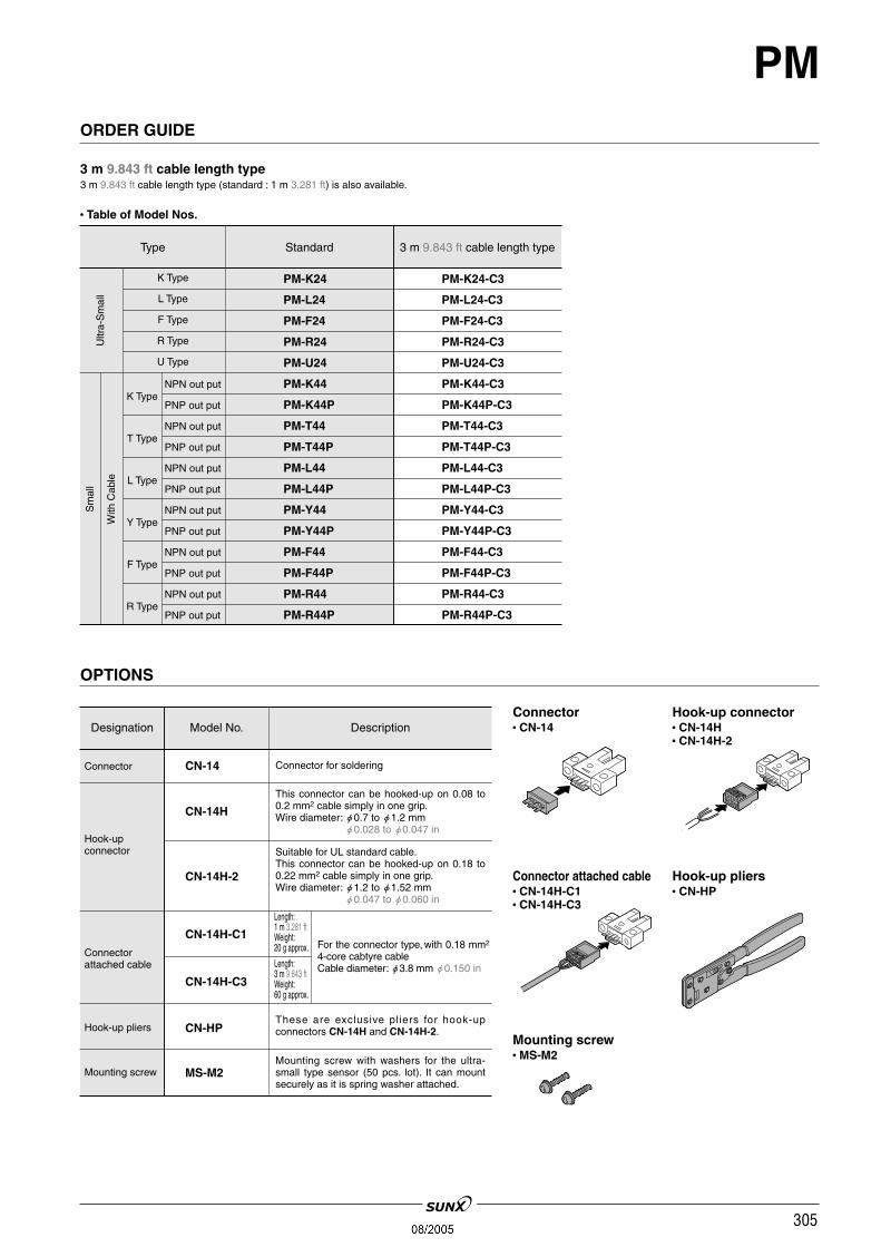
Type Standard 3 m 9.843 ft cable length type
Ultr
a-S
mal
lS
mal
l
PM-K24
PM-L24
PM-F24
PM-R24
PM-U24
PM-K44
PM-K44P
PM-T44
PM-T44P
PM-L44
PM-L44P
PM-Y44
PM-Y44P
PM-F44
PM-F44P
PM-R44
PM-R44P
PM-K24-C3
PM-L24-C3
PM-F24-C3
PM-R24-C3
PM-U24-C3
PM-K44-C3
PM-K44P-C3
PM-T44-C3
PM-T44P-C3
PM-L44-C3
PM-L44P-C3
PM-Y44-C3
PM-Y44P-C3
PM-F44-C3
PM-F44P-C3
PM-R44-C3
PM-R44P-C3
With
Cab
le
K Type
L Type
F Type
R Type
U Type
K Type
T Type
L Type
Y Type
F Type
R Type
NPN out put
PNP out put
NPN out put
PNP out put
NPN out put
PNP out put
NPN out put
PNP out put
NPN out put
PNP out put
NPN out put
PNP out put
ORDER GUIDE
3 m 9.843 ft cable length type3 m 9.843 ft cable length type (standard : 1 m 3.281 ft) is also available.
OPTIONS
Designation Model No. Description
Hook-upconnector
Connectorattached cable
Hook-up pliers
Connector
CN-14H
CN-14
CN-14H-C1
CN-14H-C3
CN-HP
This connector can be hooked-up on 0.08 to0.2 mm2 cable simply in one grip.Wire diameter: "0.7 to "1.2 mm
"0.028 to "0.047 in
Suitable for UL standard cable.This connector can be hooked-up on 0.18 to0.22 mm2 cable simply in one grip.Wire diameter: "1.2 to "1.52 mm
"0.047 to "0.060 in
Connector for soldering
Length:1 m 3.281 ftWeight:20 g approx.
Length:3 m 9.843 ftWeight:60 g approx.
For the connector type, with 0.18 mm2
4-core cabtyre cableCable diameter: "3.8 mm "0.150 in
These are exclusive pliers for hook-upconnectors CN-14H and CN-14H-2.
Mounting screw MS-M2Mounting screw with washers for the ultra-small type sensor (50 pcs. lot). It can mountsecurely as it is spring washer attached.
Connector• CN-14
Hook-up pliers• CN-HP
Hook-up connector• CN-14H• CN-14H-2
Connector attached cable• CN-14H-C1• CN-14H-C3
Mounting screw• MS-M2
• Table of Model Nos.
CN-14H-2

306
PMSPECIFICATIONS
Type
NPN output type
Item PNP output type
ModelNo.
Ultra-small Small
With flexible cable With cable With connector
PM-24 PM-24-R PM-44 PM-54
PM-44P PM-54P
5 mm 0.197 in (fixed)
0.81.8 mm 0.0310.071 in opaque object
0.05 mm 0.002 in or less
0.03 mm 0.001 in or less
5 to 24 V DC10 % Ripple P-P 10 % or less
15 mA or less
<NPN output type>NPN open-collector transistor
• Maximum sink current: 50 mA• Applied voltage: 30 V DC or less (between output and 0 V)• Residual voltage: 0.7 V or less (at 50 mA sink current)
0.4 V or less (at 16 mA sink current)
DC-12 or DC-13
Incorporated with 2 outputs: Light-ON / Dark-ON
Under light received condition: 20 !s or lessUnder light interrupted condition: 100 !s or less (Response frequency: 1 kHz or more)(Note 1)
Vermilion LED (lights up under light received condition)
3 (Industrial environment)
25 to55 C 13 to131 F (No dew condensation or icing allowed), Storage: 30 to80 C 22 to176 F
35 to 85 % RH, Storage: 35 to 85 % RH
Fluorescent light: 1,000 ?x at the light-receiving face
EN 50081-2, EN 50082-2, EN 60947-5-2
1,000 V AC for one min. between all supply terminals connected together and enclosure
50 MΩ, or more, with 250 V DC megger between all supply terminals connected together and enclosure
10 to 2,000 Hz frequency, 1.5 mm 0.059 in amplitude in X, Y and Z directions for two hours each
15,000 m/s2 acceleration (1,500 G approx.) in X, Y and Z directions for three times each
Infrared LED (non-modulated)
Enclosure: PBT, Slit cover: Polycarbonate, Terminal part [PM-54(P) only]: Solder plated
0.09 mm2 4-core cabtyre cable [PM-24-R: 0.1 mm2 flexible, oil and heat resistant cabtyrecable (Note 4)], 1 m 3.281 ft long
Extension up to total 100 m 328.084 ft is possible with 0.3 mm2, or more, cable.
10 g approx. 15 g approx. 3 g approx.
Sensing range
Minimum sensing object
Hysteresis
Repeatability
Supply voltage
Current consumption
Output
Utilization category
Output operation
Response time
Operation indicator
Pollution degree
Ambient temperature (Note 2, 3)
Ambient humidity
Ambient illuminance
EMC
Voltage withstandability
Insulation resistance
Vibration resistance
Shock resistance
Emitting element
Material
Cable
Cable extension
Weight
Env
ironm
enta
l res
ista
nce
<PNP output type>PNP open-collector transistor
• Maximum source current: 50 mA• Applied voltage: 30 V DC or less (between output andV)• Residual voltage: 0.7 V or less (at 50 mA source current)
0.4 V or less (at 16 mA source current)
Notes: 1) The response frequency is the value when the disc, given in the figure below, is rotated.
Notes: 2) In case the ultra-small type PM-24(-R) is used at an ambient temperature of 50 C 122 F, or more, make sure to mount it on a metal body.Notes: 3) Take care that the flexibility of the PM-24-R cable is lost if the ambient temperature in near 10 C 14 F.Notes: 4) The cable of PM-24-R is a flexible cable usable on a moving base. When the sensor is mounted on a moving base, fix the sensor cable joint so that
stress is not applied to it.

307
PMI/O CIRCUIT AND WIRING DIAGRAMS
PM-24 PM-24-RPM-44 PM-54 NPN output type
I/O circuit diagram Wiring diagram
Symbols ... ZD1, ZD2: Surge absorption zener diodeTr1, Tr2 : NPN output transistor
Output operation
Light-ON
Dark-ON
Black
White
Output 1
Output 2
Color code Output operation
Notes: 1) Make sure to connect terminals correctly as the sensor does notincorporate a reverse polarity protection circuit.
Notes: 1) Further, the output is not incorporated with a short-circuit protectioncircuit. Do not connect it directly to a power supply or a capacitiveload. Faulty wiring may result in damage.
Notes: 2) The color code of the connector attached cable is also the same.Notes: 3) Ensure to insulate the unused output wire.
PM-44PPM-54P PNP output type
I/O circuit diagram Wiring diagram
Output operation
Light-ON
Dark-ON
Black
White
Output 1
Output 2
Color code Output operation
Symbols ... ZD1, ZD2: Surge absorption zener diodeTr1, Tr2 : PNP output transistor
Notes: 1) Make sure to connect terminals correctly as the sensor does notincorporate a reverse polarity protection circuit.
Notes: 1) Further, the output is not incorporated with a short-circuit protectioncircuit. Do not connect it directly to a power supply or a capacitiveload. Faulty wiring may result in damage.
Notes: 2) The color code of the connector attached cable is also the same.Notes: 3) Ensure to insulate the unused output wire.
Sensing position Sensing position
SENSING CHARACTERISTICS (TYPICAL)
PM-24(-R) Ultra small typePM-44(P)PM-54(P) Small type

308
PMPRECAUTIONS FOR PROPER USE
0.08 to 0.1 mm2 Up to 5 m 16.404 ft
0.2 mm2 Up to 10 m 32.808 ft
0.3 mm2 Up to 20 m 65.617 ft
Mounting• When fixing the sensor with screws, use M3 screws [M2 screws in case of PM-24(-R)] and the tighteningtorque should not exceed the values given below.Further, use small, round type plain washers.(M3: "6 mm "0.236 in, M2: "4.3 mm "0.169 in)
Note: In case the ultra-small typePM- 24(-R) is used at anambient temperature of50 C122 F, or more, make sureto mount it on a metal body.
Model No. Tightening torque
PM-24(-R)
PM-44(P)
PM-54(P)00.5 Nm
0.15 Nm
Cable extension• Cable extension is possible up to an overall length of 100 m328.084 ft with a 0.3 mm2, or more, cable. However, sincea voltage drop shall occur due to the cable extension,ensure that the power supply voltage at the end of thecable attached to the sensor or at the sensor terminals iswithin the rating.
• But, when the overall cable length, including the cableattached to the sensor, is as given below, there is no needto confirm the voltage.
Conductor cross-section area Total cable length
This product is not a safety sensor. Its use is notintended or designed to protect life and prevent bodyinjury or property damage from dangerous parts ofmachinery. It is a normal object detection sensor.
Make sure to connect terminals correctly as thesensor does not incorporate a reverse polarityprotection circuit.Further, the output is not incorporated with a short-circuit protection circuit. Do not connect it directly toa power supply or a capacitive load. Faulty wiringmay result in damage.
Others• Since the sensor is intended for use
inside machines, no special counter-measures have been taken againstextraneous light. Take care that extra-neous light is not directly incident onthe beam receiving section.
• Do not use during the initial transient time (50 ms) after thepower supply is switched on.
• The cable of PM-24-R is a flexible cable usable on amoving base. When the sensor is mounted on a movingbase, fix the sensor cable joint so that stress is not appliedto it.
• Take care that the flexibility of the PM-24-R cable is lostif the ambient temperature is near 10 C 14 F.
All models

309
PMPRECAUTIONS FOR PROPER USE
PM-54PM-54P
CN-14H CN-14H-2
0.08 to 0.2 mm2 0.18 to 0.22 mm2
(AWG28 to AWG24) (AWG25 to AWG24)
"0.7 to "1.2 mm "1.2 to "1.52 mm"0.028 to "0.047 in "0.047 to "0.060 in
Conductor cross-section area
Wire diameter
Wire insulationmaterial
Crimping of hook-up connectors CN-14H and CN-14H-2
Cautions in plugging or unplugging a connector
1 Strip the cable sheath 15 mm 0.591 in, or more, and insert thewires into the connector insertion holes till the wire tips reachthe end.
2 Crimp with the exclusivehook-up pliers CN-HP.
ItemModel No.
Crimping method
Arrangement of connector terminals
Note: Wire at Pin No.1 or 2 as per requirement.
V: V1: Output 1 (Light-ON)
(Note) Power supply2: Output 2 (Dark-ON)
0 V : 0 V
1 Insert a connector straight into asensor until the connector lug islocked by the sensor hook.
2 When unplugging, give as muchstress as a connector lug can berelieved from a hook. Then unplug it.
Caution: Be sure to hold a connectorwhen plugging or unpluggingit. Do not hold a terminal or acable when plugging orunplugging the connector.Otherwise, it wil l cause apoor contact.
Notes: 1) When attaching or detach-ing the connector fitted witha cable, make sure to holdthe connector firmly beforeproceeding.
Notes: 2) After crimping, do not pull onthe cable.
• Prior to using the sensor, affix the cable in a way as toavoid direct stress on the crimped part.
Soldering (Both connector CN-14 and sensor)• If soldering is done directly on the terminals, strictlyadhere to the conditions given below.
Soldering temperature 260 C 500 F or less
Soldering time 3 sec. or less
Soldering position Refer to the below figure
Caution: Make sure to use the exclusive hook-up pliers CN-HP.Commercially available pliers cannot be used.
Vinyl chloride or soft poly-ethylene
• Do not plug or unplug a connector more than 10times.
• Be sure not to give stress more than 5 N to a ter-minal of both a connector and a sensor.If you do not follow the above cautions, it willcause a poor contact.
Procedures of plugging or unplugging a connector

310
PMDIMENSIONS (Unit: mm in)
PM-F24PM-F24-R Sensor
PM-U24PM-U24-R Sensor
PM-K44PM-K44P Sensor
PM-R24PM-R24-R Sensor
PM-K24PM-K24-R
PM-L24PM-L24-RSensor Sensor

311
PMDIMENSIONS (Unit: mm in)
PM-Y44PM-Y44P Sensor
PM-R44PM-R44P Sensor
PM-K54PM-K54P Sensor
PM-F44PM-F44P Sensor
PM-T44PM-T44P
PM-L44PM-L44PSensor Sensor

312
PMDIMENSIONS (Unit: mm in)
PM-Y54PM-Y54P Sensor
PM-R54PM-R54P Sensor
PM-F54PM-F54P Sensor
mTerminal part (PM-54, PM-54P)
PM-T54PM-T54P
PM-L54PM-L54PSensor Sensor

313
PMDIMENSIONS (Unit: mm in)
CN-14HCN-14H-2 Hook-up connector (Optional)Connector (Optional)CN-14
Connector attached cable (Optional)CN-14H-C1CN-14H-C3
• Cable length L
Model No.
CN-14H-C1
CN-14H-C3
Cable length
1 m 3.281 ft
3 m 9.843 ft