Embed Size (px)
Citation preview
PM SPECIAL FEATURE
In the commercial sector, such as the automotive industry, there is a constantdemand for high density, net shape parts
at an affordable cost. At the moment automo-tive parts, such as powertrain gears for high-performance applications, are typicallymachined from forged and wrought blanks.Due to high machining costs, these compo-nents are much more expensive than conventional press and sinter powder metal-lurgy (PM) parts. DMC is a new PM processthat can produce components like these atcosts comparable to the single-press, single-sinter route. In addition, DMC technology isalso expected to find use in applicationswhere special shapes, characterized by radially symmetric geometries and/or longlength/diameter (L/Ds), are required.
Magnetic forces have been used for morethan two decades in high rate metal forming1
and powder compaction2,3. The same electro-magnetic based pulse forces are used in DMCto realize net shape powder consolidation4.The powder pressing route makes use oftransmitted impact energy in a process analo-gous to driving a nail into a board with a
hammer. While almost any material can becompacted to full density using a sufficientlylarge impact pressure, the important benefitsof magnetic powder compaction when com-pared to die pressing are higher green densi-ties and higher aspect ratios.
The basic principles of the DMC processare shown in Figure 1. Powders are filled in aconductive container (armature) placed in thebore of a high field coil. The coil is pulsed witha high current to produce a magnetic field inthe bore that, in turn, induces currents in thearmature. The induced currents interact withthe applied magnetic field to produce aninwardly acting magnetic force that collapsesthe tube, thereby compacting the powder. Thearmature is launched into the powders with alarge kinetic energy within a few microsec-onds of the compaction cycle. The powders arepressed to full density via the transmittedimpact energy, with the entire compactionoccurring in less than one millisecond.
The process steps of DMC are similar toconventional PM and include tooling for com-paction, powder filling, part extraction andsintering, as well as the optional steps of sizing and finishing. In most commercialapplications the powder filling and com-paction are done in air at room temperature.The filling can also be carried out in specialenvironments, such as in an inert gas or othercover gases, for special applications. The pow-ders can also be compacted at elevated tem-peratures with suitable system modifications.
The MAGNEPRESSTM system used in theDMC process consists of four subsystems –pulsed power system, electromagnetic fieldcoil, material handling capabilities, and pro-grammable logic controller (PLC) systems.
MPR February 2000
Magnetic compaction process nears market
0026-0657/00/$- see front matter ' 2000, Elsevier Science LtdAll rights reserved
Dynamic magnetic compaction (DMC) is aninnovative, high-performance powder com-paction technology with the potential to takethe powder metallurgy industry into new mar-kets. Net shape helical gears for powertrainapplications are among the parts currentlyunder development using the process. BhanuChelluri, Ed Knoth, Dave Bauer and JohnBarber of IAP Research in Dayton, OH, USA,outline the process and its capabilities.
CurrentMagnetic fluxMagnetic pressure
Compacted
CoilArmature Powder
FIGURE 1: The principles of the DMC process.
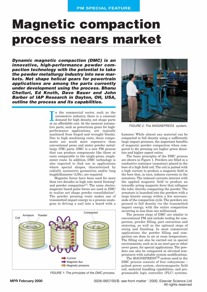
FIGURE 2: The MAGNEPRESS system.

PM SPECIAL FEATURE
The power supply has a modular design andhas been designed to accommodate expandingenergy needs. High production rates up to tenparts per minute can be achieved with thissystem. Material handling capabilities, suchas powder filling and transportation of filledcassettes, can be easily integrated into thesystem for a given application. Figure 2 showsa typical MAGNEPRESSTM system.
PropertiesA number of steel alloy powders have beencompacted using the DMC process, withFigure 3 showing the as-pressed densityachieved in a variety of these materials. In noinstance were lubricants added to any ofthese powders. In most steels, densitiesgreater than 95% were achieved after DMCcompaction with the 4405 alloy being com-pacted to a density >97% of full density. Theprocess parameters used for some alloys, indi-cated in Figure 3, were not optimized andhigher densities than shown are possible.
The DMC compacted steels were sinteredat conventional PM sintering temperaturesand were easily heat treatable. Hardness lev-els greater than 50 HRC were achieved inDMC processed 4405 alloys. A systematicevaluation of the density and mechanicalproperties on test samples made of 4405 steelpowders has been carried out using ASMstandards. Test pieces were magnetically com-pacted at different pressures and sintered at1180°C for 20 minutes in dissociated ammo-nia. The measured mechanical properties,such as transverse rupture strength (TRS),tensile, hardness and unnotched impact ener-gy, are higher than conventionally pressedbars and, indeed, are close to those of mal-leable cast iron with 2-2.5% nodular carbon inthe matrix material. The green density of 7.2g.cm-3 obtained via DMC yielded a TRS valueof 42.5 MPa, whereas a conventionallypressed sample of the same density had astrength of 18 MPa. In higher density (7.5-7.6g.cm-3) DMC samples, transverse strengthvalues close to 58-60 MPa were obtained. Asshown in Figure 4, tensile and yield strengthof DMC samples varied from 550-675 MPaand 425-525 MPa respectively for the densityrange of 7.2-7.6 g.cm-3.
Tensile elongation of DMC material was 4-6%, which is typical of cast samples. Theimpact energy of (unnotched) DMC bars isexcellent at 81.3 J.
DMC partsThe DMC process is ideally suited to producenet shape parts with cylindrical symmetry, thinwalled tubes, high aspect ratio components andparts with internal features. Shapes and sizesof typical parts produced so far from powdersrange from 12.7 mm diameter x 76.2 mm longto 127.0 mm diameter x 25.4 mm long.
One of the applications being developed isa transmission ring gear of AGMA 9 rating forautomotive powertrain applications. Theobjectives of this effort are to replace the cast
and machined gear with a lower cost netshape PM gear and to increase the power den-sity through enhanced material properties.The resulting gear must, of course, meet geo-metrical tolerances after sintering and heattreatment. In DMC gears the shrinkage anddistortion are at a minimum due to full densi-ty in the teeth. Initial development effortshave been focused on achieving the targetdensity, developing tooling that can survivethe dynamic compaction conditions, and pro-ducing the desired geometry. Figure 5 showstypical net shape parts that are formed viaDMC pressing and the tolerances achieved.
Ignition cores for electronic-ignition sys-tems are another application requiring high
MPR February 2000
7.6
7.8
7.4
7.2
7.0
6.8
6.6
Den
sity
g/c
c
100% 99.87%
98% 97.3%
93.8%88.9%
90.3%
93%
94.23%
100%
1001
HP
4401
4401
w0.
5% g
raph
ite
3% S
i ste
el
304
SS
M2
tool
ste
el
17-4
PH
SS
5100
A
Pla
stic
coa
ted
iron
4405
pre
allo
yed
FIGURE 3: The densities achieved for various ferrous alloys using theDMC process.
650
700
600
550
500
450
400
350
3007.1 7.2 7.3 7.67.57.47
Density (g/cc)
Ten
sile
/yie
ld s
tren
gth
(MP
a)84 M-tensile
84 M yield
DMC-yield
Conv P/M-yield
Conv P/M-tensile
DMC - tensile
FIGURE 4: Tensile and yield strengths of DMC processed material ascompared to 84M-malleable cast iron (2.5% nodular carbon) samples.
FIGURE 5: Typical shapes of parts produced with the DMC process.
Large parts (helical gearafter sintering)
ID 4.750–0.002 ID runout ≤ 0.010
High L/D parts L/D 5.8OD 0.520–0.002Length 3.038–0.009 Density 7.57–0.05 g.cm-3

PM SPECIAL FEATURE
density and high L/D parts. This effort is currently in prototype test stage. Similarlyapplications, such as motor rotor and statorparts, are expected to benefit from the netshape capabilities of the DMC process.
Several ring gears produced via theprocess are currently being assessed for theirdimensional characteristics. In the first batchof ten gears that have been pressed and sin-tered the minor diameter of each gear beforeand after sintering showed similar shrinkageof less than ±0.025 mm. The ProcessPerformance (Ppk) was 3.56 on the minordiameter with a centred tolerance band of0.25 mm.
The gear run out data on the green andsintered DMC parts was measured. Run outfor most of the measured gears correlatedwith the initial run out measured on thearmatures (copper drive tubes). The gear toolwith AGMA rating of 11-12 was used for thefirst batch. The gears made with this toolshowed some lead errors that are believed tooriginate from the tool. The gear tool mea-sured before and after gear manufacturingshowed no deterioration in quality during themanufacture cycle. We conclude that to manu-facture higher quality (AGMA 9-10) gears viaDMC compaction, the tool rating has to behigher with reduced, or no, lead and involuteerrors. Work with higher AGMA rating toolsis under way.
Gear teeth density measurements havebeen carried out using porosity analysis fromoptical micrographs. The density profile in thegear show that the teeth are denser than the
core. The density of the tooth tip was 7.6 g.cm-3,while at the root it was 7.55 g.cm-3. The densi-ty at the outer edge of the gear dropped to 7.4g.cm-3. The presence of fine crack lines alongthe tooth was also observed. Further studyand analysis are being conducted to identifythe potential causes for these cracks and waysto eliminate them.
Magnets and motorsThe DMC process has the potential to revolu-tionize the way that motors and generatorsare designed and manufactured – net shapestators and rotors from powder materialscould be made directly in a single step withnew designs. This could result in lower pro-duction costs and higher performance. Adevelopment effort to study and implementsuch a manufacturing process has begun.
The DMC process is also being used todevelop high-performance bonded neodymi-um iron boron and sintered samarium cobalt(2:17) magnets. It has been demonstratedthat DMC compacted bonded neodymium ironboron magnets exhibit a 15-20% increase inmagnet performance (energy product) due tohigher density relative to conventionallyprocessed magnets. In addition to high densi-fication, another benefit of DMC is its rapidsub-millisecond compaction. This feature aidsin preservation of special microstructuresincluding ultra-fine grain size. One suchexample, shown in Figure 6, is samariumcobalt magnetic powders (3-6 µm grain size)compacted using two different compactionmethods – cold isostatic pressing (CIPing)and DMC magnetic pressing. Both sampleswere subject to the same sintering cycle in thesame furnace. Figure 6 shows the dramaticdifference in microstructures in these sin-tered samples. The DMC sample retained thefine grain structure of the starting powderswhile the CIPed specimen showed anincreased grain size of 200 µm after sintering.The starting green density was 65% for CIPand 85% for DMC, respectively. A study isunder way to understand the underlyingmechanisms controlling the grain size reten-tion and to exploit the benefit of fine grainsize material.
MPR February 2000
Powder compacted Powder particle Powder Green density Propertysize morphology (%TD)
Soft ceramic HTSC 6 m Irregular >98 High critical currentTungsten steel 45 m Irregular 99.9 High penetrationcomposites powerAlumina 30 m Irregular >75 Low shrinkageNano alumina 20 m Irregular >75 Nano grain size
retention for transparency
Aluminium 7075 20-30 m Irregular 100 High ductility for MMC net shape
Tungsten 3-5 µm Irregular >85 Low shrinkage and scrap
Salt N/A N/A >98 Ease of shape forming
Table 1: Different materials compacted using dynamic magnetic pressing (DMC)
FIGURE 6: Scanning electron micrographs of samarium cobalt powders compacted by DMC (left) and CIP (right), sintered under the same
conditions.

PM SPECIAL FEATURE
Other powdersTable 1 summarizes various powders of different grain size and morphology thathave been compacted using the DMCprocess. For each material the particle sizeand green density achieved along with thedesired property enhancement is tabulated.For all of the powders compacted, the DMCgreen density was higher than that achievedthrough conventional methods. In hard-to-compress materials, such as tungsten, tung-sten carbide and ceramics, the high greendensity achieved via net shape DMC process-es reduced shrinkage in the sintered partthereby reducing or eliminating the need forfinal part machining. For example, shrink-age of 17% was achieved in a tungsten car-bide powder processed via DMC comparedwith 24% shrinkage through conventionalmethods. Similar results have been observedin ceramic materials processed via DMC.
With a number of applications now almostready for commercial implementation, newapplications are continuously being sought anddeveloped for the DMC process. At the sametime, the magnetic press system has also beendeveloped for industrial operation and the firstproduction systems are now operating.
AcknowledgmentThe transmission ring gear for powertrainapplications is being developed under a USDepartment of Commerce funded AppliedTechnology Program (ATP) titled ‘The NextGeneration Industrial Production Process forHigh Density Powder Metal Products’. Thejoint venture members of this program are IAPResearch Inc, GM Corp and GKN SinterMetals Inc. The work associated with ringgears was conducted as a team effort thatincludes William Jandeska, Young Kim andJohn Flynn of GM Powertrain, and, TerryCadle and Joel Mandel of GKN SinteredMetals. The motor applications are beingdeveloped under a second ATP titled ‘Motorsand generators for the 21st century’ with IAPResearch Inc, Delco Remy and Select Tool andDie Corp as joint venture members.
References(1) Shock Waves and High Strain Rate
Phenomena in Metals, Eds: M.A. Meyersand L.E. Murr, Plum Press, pp. 913-1019.
(2) W. H. Gourdin, ‘Dynamic Consolidation ofMetal Powders’, Progress in MaterialScience, Vol. 30, (1986), pp. 39-80.
(3) Von V. Mirnov, Plansee-Berichte FurPulvermetallurgie, Vol. 24, (1976), p. 175.
(4) Bhanumathi Chelluri and John P. Barber,United States Patent Numbers 5,405,574;5,611,139; 5,639,797; 5,611,230.
Contact: John Barber or Bhanu ChelluriIAP Research Inc2763 Culver Ave, Dayton, OH 45429, USA.Tel: +1-937-296-1806;Fax: +1-937-296-1114;E-mail: s a l e s @ i a p . c o m ■
MPR February 2000