Embed Size (px)
Citation preview

PLUS-DAC:An Admission Control Scheme inIEEE 802.11e Wireless LANs.
M. Tech. Project Dissertation
Submitted in partial fulfillment of the requirements
for the degree of
Master of Technology
by
Kiran Kumar Gavini
Roll No: 03329020
under the guidance of
Prof. Varsha Apte
and
Prof. Sridhar Iyer
Kanwal Rekhi School of Information Technology
Indian Institute of Technology, Bombay
2005


Dedicated to my mother


Abstract
With increasing demand of support for realtime applications, there is a compelling need for
Quality of Service (QoS) in present day wireless LANs. IEEE 802.11 Medium Access Control
(MAC) has become a defacto standard for wireless LANs, but there are many inherent QoS
limitations in the base standard, as it was basically developed for best effort data services.
The IEEE 802.11 Task Group E (TGe), is about to ratify a QoS extension to the base 802.11
standard namely IEEE 802.11e. The IEEE 802.11e standard provides many mechanisms for
QoS support at the MAC layer level. However, even the servicedifferentiation provided in
IEEE 802.11e is not enough to meet the QoS requirements of time bounded multimedia traffic
at high load. These can be better satisfied, if we employ Admission Control and Bandwidth
Reservation mechanisms.
Another important concern in WLANs is channel utilization.Generally, partitioning based
reservation schemes do static division of bandwidth. When bandwidth is divided statically,
often, more bandwidth can get allocated to a category which is currently not offering much
traffic to the network, resulting in under-utilization of the bandwidth resources. More over, the
bandwidth partitioning should not be purely based on the priority of the traffic.
We propose a measurement based distributed admission control mechanism, for the IEEE
802.11e Wireless Local Area Network (WLAN) functioning in infrastructure mode. We call the
scheme PLUS-DAC (Priority, Load and Utilization based Scheme for Distributed Admission
Control). PLUS-DAC measures the load and utilization in theBSS and adapts the Transmission
Opportunity (TXOP) reservation dynamically. Our results show that, PLUS-DAC can achieve
quasi-optimal utilization and continue to satisfy QoS guarantees given to multimedia flows.


Acknowledgements
I like to take this opportunity to express my deep sense of gratitude for Prof. Varsha Apte
andProf. Sridhar Iyer , for providing excellent guidance and support. It is because of their
constant interest and assistance that this project has beensuccessful. I would like to thank all the
members of thePerfNet Group at CSE Department, IIT Bombay, for their valuable suggestions
and helpful discussions.
I would also like to thank every member ofKReSIT family who have been a source of
encouragement and inspiration throughout the duration of this project.
I would like to thank Pierre Ansel, Qiang Ni and Thierry Turletti for making their FHCF
Implementation inns-2available, which we have extended in our Simulations.
Finally I would be thankful to myfamily andfriends who have given me emotional support
through out the duration of the project.
Kiran Kumar Gavini
IIT Bomay
iii


Contents
Abstract i
Acknowledgements iii
List of figures vii
List of tables ix
1 Introduction 1
1.1 Wireless and Convergence - The Future . . . . . . . . . . . . . . . .. . . . . 1
1.2 Challenges in Wireless Networks . . . . . . . . . . . . . . . . . . . .. . . . . 1
1.3 Need for Quality of Service . . . . . . . . . . . . . . . . . . . . . . . . .. . . 2
1.4 QoS in IEEE 802.11 WLANs . . . . . . . . . . . . . . . . . . . . . . . . . . . 3
1.5 Problem Statement . . . . . . . . . . . . . . . . . . . . . . . . . . . . . . . .4
1.6 Thesis outline . . . . . . . . . . . . . . . . . . . . . . . . . . . . . . . . . . .4
2 IEEE 802.11 WLAN Standard 7
2.1 System Architecture . . . . . . . . . . . . . . . . . . . . . . . . . . . . . .. . 7
2.2 DCF: Distributed Coordination Function . . . . . . . . . . . . .. . . . . . . . 8
2.3 PCF:Point Coordination Function . . . . . . . . . . . . . . . . . . .. . . . . 10
3 Overview of IEEE 802.11e QoS Standard 13
3.1 HCF Contention based Channel Access:EDCA . . . . . . . . . . . .. . . . . 14
3.2 HCF Controlled Channel Access (HCCA) . . . . . . . . . . . . . . . .. . . . 17
3.3 QoS Control . . . . . . . . . . . . . . . . . . . . . . . . . . . . . . . . . . . . 19
3.4 Traffic Specification (TSPEC) element . . . . . . . . . . . . . . . .. . . . . . 19
3.5 Enhancements to IEEE 802.11e . . . . . . . . . . . . . . . . . . . . . . .. . 20
v

4 Related Work 23
4.1 Need for Admission control . . . . . . . . . . . . . . . . . . . . . . . . .. . . 23
4.2 Admission Control based on Achievable Throughput . . . . .. . . . . . . . . 23
4.3 Admission Control based on Estimated Service Rate . . . . .. . . . . . . . . 24
4.4 HARMONICA . . . . . . . . . . . . . . . . . . . . . . . . . . . . . . . . . . 24
4.5 Partitioning Based Distributed Admission Control . . . .. . . . . . . . . . . . 25
5 PLUS-DAC: Proposed Scheme 27
5.1 TXOP Partitioning and Reservation . . . . . . . . . . . . . . . . . .. . . . . 28
5.2 Distributed Admission Control at each QSTA . . . . . . . . . . .. . . . . . . 30
5.3 Proposed Architecture . . . . . . . . . . . . . . . . . . . . . . . . . . . .. . 31
5.4 Implementation Details . . . . . . . . . . . . . . . . . . . . . . . . . . .. . . 32
5.4.1 Important Changes . . . . . . . . . . . . . . . . . . . . . . . . . . . . 33
6 Simulation and Results 35
6.1 Simulation Setup and Traffic Description . . . . . . . . . . . . .. . . . . . . . 35
6.2 Performance Metrics Considered . . . . . . . . . . . . . . . . . . . .. . . . . 37
6.3 High Priority Scenario . . . . . . . . . . . . . . . . . . . . . . . . . . . .. . 37
6.4 Low priority scenario . . . . . . . . . . . . . . . . . . . . . . . . . . . . .. . 42
7 Conclusion and Future Research 47
Bibliography 48

List of Figures
2.1 802.11 AdHoc Network . . . . . . . . . . . . . . . . . . . . . . . . . . . . . .8
2.2 802.11 Infrastructure Based Network . . . . . . . . . . . . . . . .. . . . . . . 8
2.3 NAV updating in 802.11 DCF . . . . . . . . . . . . . . . . . . . . . . . . . . 9
2.4 The PCF Limitations . . . . . . . . . . . . . . . . . . . . . . . . . . . . . . .11
3.1 Queue model in the IEEE 802.11e QSTA . . . . . . . . . . . . . . . . . .. . 14
3.2 Channel Access in 802.11e . . . . . . . . . . . . . . . . . . . . . . . . . .. . 15
3.3 IEEE 802.11e super frame . . . . . . . . . . . . . . . . . . . . . . . . . . .. 17
3.4 Qos Control Field in 802.11e Frame Header sent by non-AP STA . . . . . . . . 19
4.1 An Example TXOP partitioning . . . . . . . . . . . . . . . . . . . . . . .. . 26
5.1 TXOP Grant Calculation . . . . . . . . . . . . . . . . . . . . . . . . . . . .. 29
5.2 Distributed Admission Control at QSTA . . . . . . . . . . . . . . .. . . . . . 31
5.3 Proposed Architecture . . . . . . . . . . . . . . . . . . . . . . . . . . . .. . 32
6.1 Simulation Setup . . . . . . . . . . . . . . . . . . . . . . . . . . . . . . . . .35
6.2 Audio latency characteristics . . . . . . . . . . . . . . . . . . . . .. . . . . . 38
6.3 VBR latency characteristics . . . . . . . . . . . . . . . . . . . . . . .. . . . . 38
6.4 CBR latency characteristics . . . . . . . . . . . . . . . . . . . . . . .. . . . . 39
6.5 Audio packet loss and latency distribution . . . . . . . . . . .. . . . . . . . . 39
6.6 VBR packet loss and latency distribution . . . . . . . . . . . . .. . . . . . . . 40
6.7 CBR packet loss and latency distribution . . . . . . . . . . . . .. . . . . . . . 40
6.8 Audio throughput characteristics . . . . . . . . . . . . . . . . . .. . . . . . . 41
6.9 VBR throughput characteristics . . . . . . . . . . . . . . . . . . . .. . . . . . 41
6.10 CBR throughput characteristics . . . . . . . . . . . . . . . . . . .. . . . . . . 41
vii

6.11 Variation ofew[i] and Total throughput . . . . . . . . . . . . . . . . . . . . . 42
6.12 Audio latency characteristics . . . . . . . . . . . . . . . . . . . .. . . . . . . 43
6.13 Audio packet loss and latency distribution . . . . . . . . . .. . . . . . . . . . 43
6.14 Video latency characteristics . . . . . . . . . . . . . . . . . . . .. . . . . . . 44
6.15 Video packet loss and latency distribution . . . . . . . . . .. . . . . . . . . . 44
6.16 Video throughput characteristics . . . . . . . . . . . . . . . . .. . . . . . . . 45
6.17 Data throughput characteristics . . . . . . . . . . . . . . . . . .. . . . . . . . 45
6.18 Variation ofew[i] and Total throughput . . . . . . . . . . . . . . . . . . . . . 45

List of Tables
3.1 802.1D Priority - AC mapping . . . . . . . . . . . . . . . . . . . . . . . .. . 15
6.1 Description of Traffic streams . . . . . . . . . . . . . . . . . . . . . .. . . . 36
6.2 PHY and MAC Parameters . . . . . . . . . . . . . . . . . . . . . . . . . . . . 36


Chapter 1
Introduction
1.1 Wireless and Convergence - The Future
As we move into the 21st century, it is becoming more apparentthat IP networks are the next
generation networks for all forms of communication. Industry surveys reveal that spending on
voice over IP(VOIP), is likely to double every year in the next decade. As VoIP is becoming
increasingly popular, the popularity will only grow asWireless LAN(WLAN)s become more
commonplace. The convergence of these two highly disruptive technologies will alter the way
enterprises communicate and do business.
Although today the voice over WLAN market is a small and immature market it is also one
with a significantly growing amount of interest and potential. A significant benefit of mixing
telephone traffic with data on a WLAN is to make use of a common infrastructure and provide
mobility. The support of a common system for both data and voice traffic is generally simpler
and less expensive than two separate entities. Currently this application appeals to markets
such as education, health-care and retail because they wereamongst the first to roll out WLAN
networks. In the longer term, all users of WLAN networks could eventually find a business case
within the context of inter-operability between WLANs and 3G networks.
1.2 Challenges in Wireless Networks
Having said that the future lies with wireless converged networks, the transformation is not an
easy process. More over the wireless community faces certain inherent challenges and con-
straints that are not imposed on their wired counterparts. We list few of the challenges here.
1. Standards: Major challenge is compliance with various existing standards and inter-
operability among them. Presently, most of the VOIP solutions for wireless LANs are
1
2 1.3. Need for Quality of Service
proprietary. Various national and international frequency regulations have to be consid-
ered in making wireless devices suitable for global operation.
2. Bandwidth: Bandwidth is the one of the most scarce resource in wireless networks.
Even with emerging high speed WLAN technologies, the available bandwidth in wireless
networks is far less than the wired links.
3. Link Errors: Channel fading and interference cause link errors and theseerrors may
sometimes be very severe. More over the effect of these errors is often global, i.e. not
local to a single node, may effect the entire network.
4. Mobility and Roaming: Existing applications should continue to run over WLANs even
while roaming the the network. The fact that wireless accessand mobility should be
hidden if not relevant.
5. Inter-operability with wired Networks: Already a lot of money has been invested on
VOIP implementations in wired LANs. Hence new WLAN mechanisms must protect this
investment by being inter-operable with the existing networks.
6. Power Constraints: Devices communicating via a WLAN are typically also wireless
devices running on battery power. Hence, WLAN must implement special power saving
modes and power management functions.
7. Safety and security: Another important concern is of safety and security. WLANs
should be safe to operate, especially regarding low radiation. Furthermore, no users
should be able to read personal data during transmission i.e., encryption mechanism
should be integrated. The network should also take into account user privacy.
1.3 Need for Quality of Service
Quality of Service (QoS) is a broad term used to describe the overall experience the user or
application will receive over a network. Generally QoS is achieved through giving importance
to prioritized applications by means of “Controlled Unfairness”. VOIP and multimedia applica-
tions are loss and delay sensitive, and need strict QoS guarantees. For a good quality multimedia
service, unidirectional latency should be less than150ms and packet loss should be less than
10%. The LAN component of these requirements should be more stringent. More over end to

1.4. QoS in IEEE 802.11 WLANs 3
end delay is non deterministic in nature due to variable processing and queuing delays, which
might lead to high jitter.
The fraction of bandwidth required by high priority traffic compared to low priority traffic
is low. For example, the bandwidth requirements of VOIP traffic with added overheads are less
than 100 Kbps (e.g. G.711, G.723 codecs). Even video conferencing applications (H.261 and
H.263 codecs) have bandwidth requirements between 100 Kbpsto 400 Kbps. MPEG video
streams have bandwidth requirements of 1-4 Mbps, but they are generally used for broadcast.
Never the less, reserving bandwidth for high priority flows is required for meeting their QoS
requirements as at high load conditions, low priority traffic tend to disturb the high priority
flows.
1.4 QoS in IEEE 802.11 WLANs
The IEEE 802.11 WLAN standard [1] has become a de-facto standard for wireless data net-
works. It has been widely accepted in various environments because of its simplicity, flexibility
and robustness against failures. With wireless LANs starting to be used for more than just data
traffic, the need for QoS provisioning has grown tremendously in the recent years. But provid-
ing QoS guarantees in a legacy 802.11 LAN can be very difficultas it is basically designed for
best effort data services.
A special task group IEEE 802.11e Task Group has been set up todevelop an extension to
the base IEEE 802.11 standard for supporting QoS mechanisms. The task group is finalizing
work on IEEE 802.11e [2], a MAC level QoS standard, which willenable the administrator to
specify a range of priorities for different kinds of packetsand control the delay requirements of
the traffic. The upcoming IEEE 802.11e provides priority based service differentiation based on
a queue model in contrast to the station model of the IEEE 802.11 standard. Each Station (STA)
supports multipleTraffic Streamsand each of the traffic streams have different priorities. The
service differentiation is implemented by choosing backoff parameters and inter-frame spaces
in such a way as to give one traffic stream priority over the other [2, 3].
IEEE 802.11e supports a new Coordination function called Hybrid Coordination Func-
tion (HCF), which includes a contention based channel access known as Enhanced Distributed
Channel Access (EDCA) as well as a polling based channel access known as HCF Controlled
Channel Access (HCCA). EDCA extends the Distributed Co-ordination Function (DCF) of the

4 1.5. Problem Statement
802.11 MAC, by allowing traffic streams to have priorities. The standard also gives provisions
to support scheduling and traffic negotiation and timer management.
1.5 Problem Statement
For any network that tries to ensure QoS, simply implementing QoS-enabling scheduling al-
gorithms is not enough.Admission Controlmechanisms are also required, so that the offered
load to the network can be kept under control. This is especially true about contention based
access mechanisms such as EDCA. At high load, the performance of EDCA degrades consider-
ably, and QoS guarantees of even high-priority traffic may not be met. Thus admission control
mechanisms for the EDCA are necessary.
Another important concern in WLANs is channel utilization,any QoS provisioning scheme
should try to achieve optimal channel utilization. Bandwidth reservation, is essential for giving
QoS guarantees to real time traffic. However, an approach based on static partitioning is not
efficient, when bandwidth is divided statically, often, more bandwidth gets allocated to a cate-
gory which is currently not offering much traffic to the network, resulting in under-utilization of
the bandwidth resources. More over, we claim that bandwidthpartitioning should not be purely
based on the priority of the traffic.
We propose a mechanism, called PLUS-DAC (Priority, Load and Utilization-based Scheme
for Distributed Admission Control). PLUS-DAC is a flexible mechanism, which monitors load
and priority and continuously adjusts the fractions of bandwidth reserved for each category to
reflect actual requirement. Through simulation in various scenarios, we show that PLUS-DAC
indeed outperforms static bandwidth reservation-based mechanisms - it is able to admit more
streams, while still meeting QoS requirements.
1.6 Thesis outline
The main objectives of this thesis are,
• to give an overview of the upcoming IEEE 802.11e standard.
• to give an insight into the current work for QoS in IEEE 802.11WLANs.
• to describe the PLUS-DAC mechanism for infrastructure based WLANs.

1.6. Thesis outline 5
• to summarize the results of simulation in various scenariosconsidered.
The thesis is outlined as follows. In the next chapter we describe channel access in 802.11
and briefly discuss the problems with the legacy standard. Inchapter 3, the currently discussed
MAC enhancements to support QoS are summarized based on the status of the standard at the
time this report is written.
In chapter 4, we discuss the need for admission control by looking in to various schemes
suggested so far in admission control for IEEE 802.11e WLANs. Then in chapter 5, we propose
a simple architecture to support admission control and explain the PLUS-DAC mechanism.
The various simulation scenarios and parameters used in thesimulation are described in
chapter 6. Following this, results of simulation and behaviour of performance metrics are
summarized. The thesis ends in chapter 7 with conclusions and future directions that can be
explored.


Chapter 2
IEEE 802.11 WLAN Standard
IEEE 802.11 MAC standard, which belongs to the family of IEEE802.x LAN standards. This
standard specifies the physical and medium access layer adapted to specific requirements of
wireless LANs. This chapter gives a brief overview of the standard and and describes its limi-
tations in providing QoS.
IEEE 802.11 MAC defines two medium access coordination functions, a mandatory coor-
dination function called Distributed Coordination Function (DCF) and an optional coordination
function called Point Coordination Function (PCF). DCF provides an asynchronous transmis-
sion based on CSMA/CA scheme. PCF provides synchronous transmission based on a central-
ized polling, but relies on the asynchronous service provided by DCF.
2.1 System Architecture
The basic service set (BSS) is the fundamental building block of the IEEE 802.11 architecture.
A BSS is defined as a group of stations that are under the directcontrol of a single scheme
(either DCF or PCF). The geographical area covered by the BSSis known as the basic service
area (BSA). Conceptually, all stations in a BSS can communicate directly with all other stations
in a BSS.
An adhoc network is a grouping of stations into a single BSS for the purposes of communi-
cations without the need for a centralized controlling entity. The IEEE 802.11 standard specifies
the term Independent BSS (IBSS) for such an adhoc network. Figure 2.1 shows an IBSS. Any
station can establish a direct communication session with any other station in the BSS, without
the requirement of channeling all traffic through a centralized entity Access Point (AP).
Infrastructure networks are established to provide wireless users with specific services and
explicit channel access. Infrastructure networks are established using APs. Figure 2.2 shows
7

8 2.2. DCF: Distributed Coordination Function
STA
STA
STA Independent BSS
Figure 2.1: 802.11 AdHoc Network
an Infrastructure based network. Range extension is provided by introducing the integration
points necessary for network connectivity between multiple BSSs. The entity thus formed is
called an Extended Service Set (ESS). The ESS consists of multiple BSSs that are integrated
together using a common distribution system (DS). The DS is kind of a backbone network that is
responsible for MAC-level transport of MAC service data units (MSDUs). The DS, as specified
by IEEE 802.11, is implementation independent i.e it could be either wired wired IEEE 802.3
Ethernet LAN, IEEE 802.4 token bus LAN, IEEE 802.5 token ringLAN, Fiber Distributed
Data Interface (FDDI), Metropolitan Area Network (MAN) or another IEEE 802.11 wireless
medium.
2.2 DCF: Distributed Coordination Function
Distributed Coordination Function operates based on the 1-persistent CSMA/CA (Carrier Sense
Multiple Access with Collision Avoidance) mechanism [1]. Any station detecting the channel
IEEE 802.X
DS: Distribution SystemPortal
STA
STA STA
STA
AP
AP
Figure 2.2: 802.11 Infrastructure Based Network

2.2. DCF: Distributed Coordination Function 9
idle for a period of DCF Inter-frame space(DIFS), performs the backoff procedure. The dura-
tion of the backoff interval is determined by Contention Window(CW), which is a multiple of
rand[0, CW ] and a slot time.CW varies fromCWmin to CWmax and slot time depends on the
PHY layer type. If the channel remain idle for a duration of DIFS plus backoff interval then
the station is allowed to transmit one MSDU (MAC Service DataUnit). If two stations try to
transmit at the same time, collision occurs. Each station acknowledges the successful transmis-
sion as there is no specific scheme for collision detection. Acknowledgment is transmitted after
SIFS (Short Inter-frame space) interval, after receiving the packet.CW is set toCWmin after
a successful transmission, and doubled after each unsuccessful transmission to avoid additional
collisions.CW value is freezed when any other station gets the access to thechannel. Carrier
sensing can be physical or virtual. Physical carrier sensing is implemented as a function called
CCA (Clear Channel Assessment) which is PHY dependent. Virtual carrier sensing mechanism
is implemented with the help of NAV (Network Allocation Vector), which is a timer updated
with the value of other stations’ transmission duration.
Figure 2.3: NAV updating in 802.11 DCF
The probability of collision generally increases with the length of the data frame. To reduce
this effect, long data frames can be fragmented, and fragments can be transmitted sequentially
as individual data frames. To avoid the hidden terminal problem [1], an optionalRTS/CTS
(Request to Send / Clear to Send) scheme can be used. The transmitting station sends a short

10 2.3. PCF:Point Coordination Function
RTS frame before transmitting the MSDU and the receiving station responds with aCTS frame
if it is ready to receive the MSDU. All other stations update their local NAV to the duration
specified in either RTS or CTS as shown in Figure 2.3. To reducethe overheads appropriate
thresholdvalues (Fragmentation threshold and RTS/CTS threshold) have to configured. For
further details refer to IEEE 802.11 standard [1].
QOS LIMITATIONS : As IEEE 802.11 is basically designed for Best Effort service, DCF has
inherent QoS limitations. DCF does not provide any service differentiation between the traffic
streams. The values of the parameters like DIFS,CWmin, andCWmax are globally same for all
the stations. The variations of CW do not depend on network conditions and are not dynamic, i.e
CW is always doubled after an unsuccessful transmission and set to CWmin after a successful
transmission.
2.3 PCF:Point Coordination Function
PCF is an optional Coordination Function suggested in IEEE 802.11, to support time bounded
services in Infrastructure mode. The radio channel is controlled by a point coordinator co-
located with the Access Point. The time is divided into repeated periods calledsuperframes,
where each super frame starts with a beacon frame sent by the point coordinator. The PC gets
priority over other stations as it waits only for PIFS (PCF Inter-Frame Space), rather than DIFS
(> PIFS). But it does not interfere with any ongoing transmissions as SIFS is less than PIFS.
Each super frame is divided into Contention Free Period(CFP) and Contention Period(CP),
with a requirement thatCP should be large enough to transmit at least one MSDU using DCF. A
beacon frame is a management frame which is transmitted by the PC at regular intervals (start of
each super frame). It contains values for various parameters required for time synchronization
and power management. The beacon frame containsCFPmax andTBTT (Target Beacon Turn
around Time) values, which are used by the STAs(Stations) toset their NAV for synchronization
purposes.CFPmax is the maximum duration of CFP, which can be terminated earlyby sending
a CF-End frame. During CFP PC polls each station by sending a CF-Poll frame, which can be
piggy backed on to the data frame for that station, if available. The polled station responds with
an acknowledgment, and if there is no response from the polled station, after PIFS interval PC

2.3. PCF:Point Coordination Function 11
polls the next station. Each STA can specify the way it can be polled, by setting the CF-Pollable
subfield of Capability Information field in Association Request and/or Re-association Request
frames. For further details refer to [1].
Figure 2.4: The PCF Limitations
QOS LIMITATIONS : PCF as it is, has various limitations. Though it is designed for provid-
ing time bounded service, the centralized polling scheme ishighly complex and inefficient. PCF
can not provide parameterized QoS, it can only allow the stations to have prioritized access to
the wireless medium. According to IEEE 802.11 standard, allthe communication during CFP
has to go through the AP which is highly inefficient.
The beacon delays and the transmission duration of the polled stations are unpredictable.
Generally at TBTT, all the stations set their NAV to a maximumvalue, thus not contending for
the channel. But according to legacy IEEE 802.11standard, STAs can start transmission even if
the MSDU delivery can not be finished before upcoming TBTT, which might result in a beacon
frame getting delayed as shown in the Figure 2.4. When a station is polled, the transmission
duration for which the STA may occupy channel is not under thecontrol of PC as data frame
may be fragmented. In 802.11a, different encoding and modulation schemes are defined, as a
result the duration of MSDU delivery can be arbitrary. Theselimitations were detailed in [4, 3].
If a station misses the previous beacon, it doesn’t have its NAV set, so it may interfere during
CFP. Further it doesn’t set its NAV at TBTT.


Chapter 3
Overview of IEEE 802.11e QoS Standard
As legacy IEEE 802.11 is inefficient for QoS, IEEE 802.11Task Group E(TGe) defines mac
level QoS enhancements to the base 802.11 MAC, referred to asIEEE 802.11e. and is about to
ratify IEEE 802.11e very soon. The overview presented in this document is based on the draft-9
of the standard. A Station that operates according to IEEE 802.11e is calledQoS supporting
Station(QSTA). One of the QSTAs which may optionally work as a centralized coordinator for
all stations in theQoS supporting Basic Service Set(QBSS) is calledHybrid Coordinator(HC),
which is generally co-located withQoS enhanced Access Point(QAP).
HCF: The major enhancement of IEEE 802.11e is the new coordination function calledHy-
brid Coordination Function(HCF) , which specifies two mechanisms - HCCA (HCF Controlled
Channel Access), which is a polling-based mechanism and EDCA (Enhanced Distributed Chan-
nel Access), which is a contention-based access mechanism.Controlled channel access can also
be used during CP, which is referred to asControlled Access Phase(CAP).
TXOP: The IEEE 802.11e introduces the notion ofTransmission Opportunity(TXOP), which
is an interval of time during which a station has a right to initiate transmissions. A TXOP is
defined by a starting time and a maximum limit on the interval.TXOP can be obtained by
either contention based channel access (called EDCA-TXOP)or controlled channel access. An
EDCA-TXOP is limited by a QBSS wide parameter calledTXOPLimit, which is broadcast by
the HC in an information field of thebeacon frame. For the controlled TXOP, TXOPLimit can
be specified by the QoS enhanced Contention Free Poll (CF-Poll). As legacy stations do not
understand the new information fields they may transmit for longer durations than allowed by
the TXOPLimit [4].
13

14 3.1. HCF Contention based Channel Access:EDCA
In IEEE 802.11e, no backoff entity is allowed to transmit, ifit can not finish before next
TBTT. This gives HC a better control over the channel. Further, any backoff entity can directly
communicate with other backoff entity with out the intervention of the QAP, calledDirect Link
(DiL). To establish DiL, a set-up procedure calledDirect Link Protocol(DLP) has to be per-
formed. In IEEE 802.11e data frames can be protected by usingRTS/CTS, with out considering
any threshold. similarly an MSDU can be fragmented into multiple MSDUs with any fragmen-
tation size. But the condition in both the cases is that transmission duration must not exceed the
TXOPLimit.
3.1 HCF Contention based Channel Access:EDCA
Enhanced Distributed Channel Access(EDCA) is the contention based channel access part of
HCF. It provides service differentiation by introducing the notion of Access Category (AC) and
parallel backoff entities with in each QSTA as shown in Fig 3.1.
single priority
802.11e QoS STA (four Access Categories)legacy 802.11 STA
high priority low priority
AC 3 AC 2 AC 1 AC 0Backoff Entity
When More than one AC tries to access in the same slot the higher AC transmits and the lower AC back offs
backoff
(CWmin[3])
(AIFS)
(CWmax[3])
(Virtual Collision)
(CWmin[2])(CWmax[2])
backoff(AIFS)
backoff
(CWmin[1])(CWmax[1])
(AIFS)
(CWmax[0])(CWmin[0])
(AIFS)
backoff
Transmission
backoff
(CWmin)(CWmax)
(DIFS)
entityBackoff
Transmission
Figure 3.1: Queue model in the IEEE 802.11e QSTA
Each backoff entity is characterized by the AC specific parameters, called EDCF parameter
sets. There are four different ACs, with four priorities AC 0.. 3, which correspond to the prior-
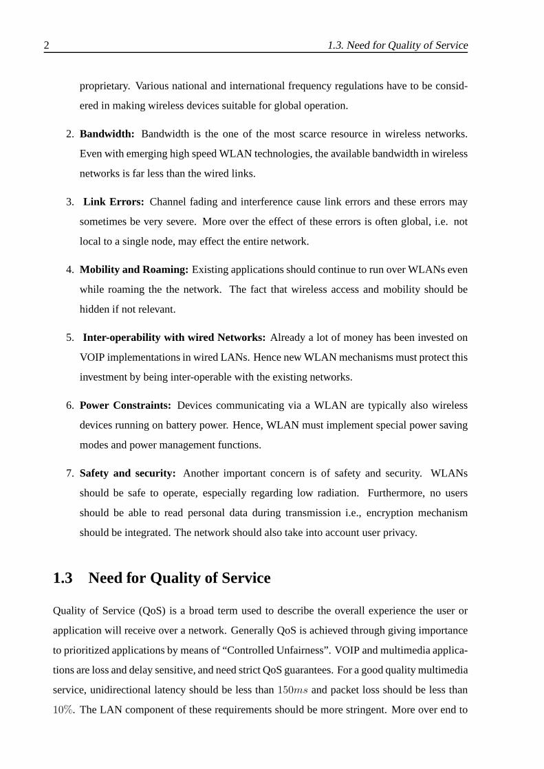
ities defined by IEEE 802.1D, as described in Table 3.1.
3.1. HCF Contention based Channel Access:EDCA 15
802.1D priority 802.1D interpretations 802.11e AC Service Type
0 Best Effort 0 best effort
1 Back Ground 0 best effort
2 ,, 0 best effort
3 Excellent Effort 1 video probe
4 Controlled Load 2 video
5 Video< 100ms delay 2 video
6 Voice and Video< 10ms delay 3 video / voice
7 Network Control 3 network control
Table 3.1: 802.1D Priority - AC mapping
These priorities can be realized by modifying the back-off procedure with EDCA parameter
sets. Each back-off entity within a QSTA, which can be thought of as a virtual station, contends
for TXOP independently. If the counters of two or more back-off entities reach zero at the same
time, the scheduler inside the QSTA resolves this by granting the TXOP to the back-off entity
with higher priority (virtual collision). Note that there is still a probability that the transmitted
frame may get collided with the transmission of a backoff entity belonging to another QSTA
(external collision).
SIFS
PIFS
AIFS[low] CW[low]
CW[high]busy channel
SIFSSIFS
AIFS[med]
(=PIFS)AIFS[high]
aSlotTime
earliest channel access time for high priority AC
back off
back offAC
low priority
High priority AC
medium priority AC
ACK
CTS
RTS
time
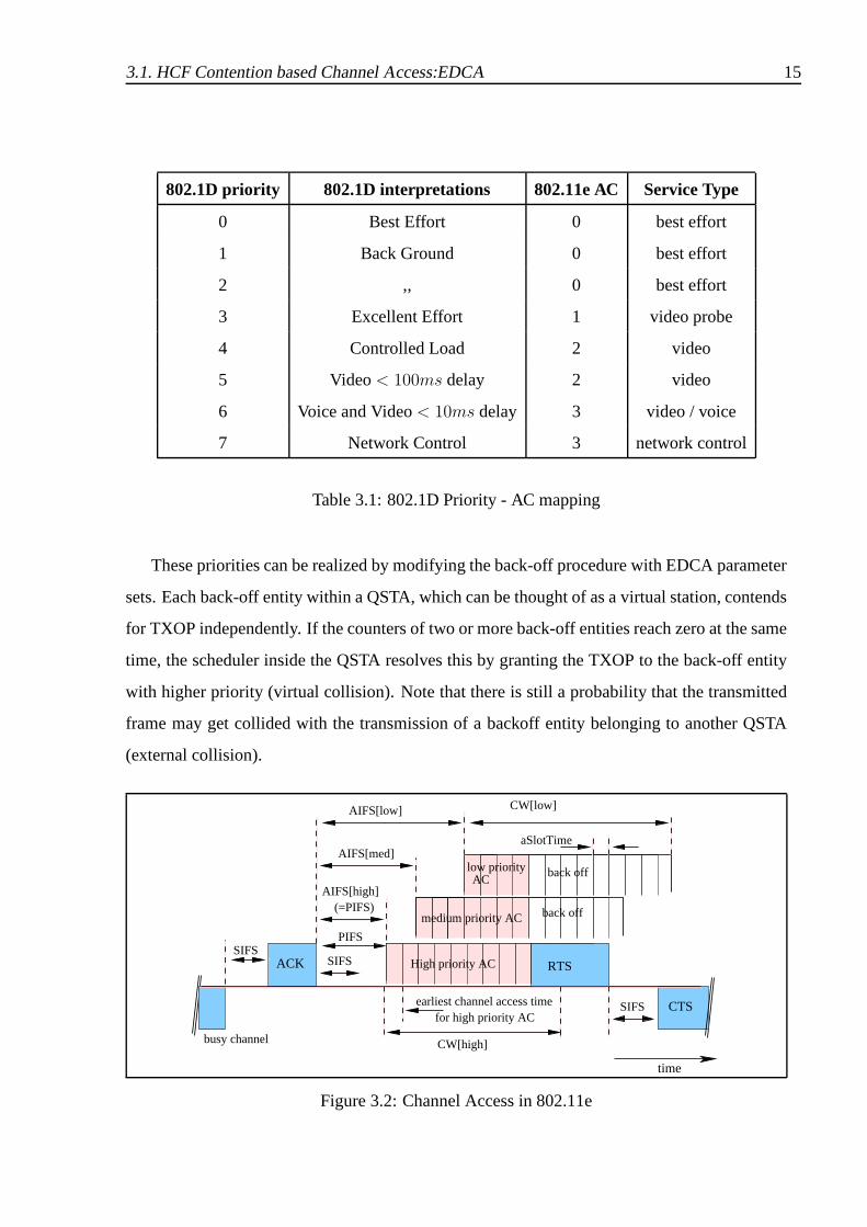
Figure 3.2: Channel Access in 802.11e

16 3.1. HCF Contention based Channel Access:EDCA
EDCA Parameters
In IEEE 802.11e, different backoff entities have differentinter frame spaces, contention win-
dows and other many other parameters. These values comprisethe EDCF parameter sets per
AC as shown in Figure 3.1. The values to be used by the backoff entity are defined by the HC
and broadcast via information fields in the beacon frames. Different backoff entities of same
AC use the same EDCF parameters . The default set of EDCA parameters are theArbitration
Inter-Frame Space(AIFS[TC]), theContention Window(CWmin[AC], CWmax[AC]) and the
Maximum TXOP(TXOPLimit[AC]).
• ARBITRATION INTER-FRAME SPACE (AIFS): In IEEE 802.11e, each backoff entity
has a different Inter frame space calledArbitration Inter-Frame Space(AIFS[AC]). The
AIFS[AC] is at least PIFS and defined using Arbitration Inter-Frame Space Number
(AIFSN [AC]) as below.
AIFS[AC] = SIFS + AIFSN [AC] · aSlotTime
• CONTENTION WINDOW: The contention window limits, (CWmin[AC], CWmax[AC]),
are dependent on the AC. Unlike legacy IEEE 802.11, an IEEE 802.11e backoff entity
chooses its backoff counter as a random number from the interval [1, CW + 1] instead
of [0, CW ]. As a result, with the minimumAIFS[AC] being PIFS, the earliest channel
access time after the channel became idle is DIFS, similar tothe legacy protocol. But pri-
ority over legacy stations can be achieved by settingAIFSN [AC] = 1 andCWmin[AC]
to a less value. Xiao [5] has shown that differentiating the inter frame space doesn’t result
in increase in the saturation throughput of the higher priority class. Thus differentiat-
ing the initial contention window size is better than differentiating inter frame space in
terms of total throughput and delay. The smallerCWmin[AC], the higher is the prior-
ity in channel access, but it has to be noted that the collision probability increases with
smallerCWmin[AC] if there are more than one backoff entity of the same AC. The po-
sitions of the contention windows are important factors in defining the relative priorities
for channel access per AC. EDCF can not support strict priorities between ACs, though
the initial contention windows are made not to overlap at all, as soon as CWs increase
upon collisions, the strict differentiation is lost [4]. Similar to CWmin[AC], the smaller
the CWmax[AC], the higher is the channel access priority, but a smallerCWmax[AC]

3.2. HCF Controlled Channel Access (HCCA) 17
value may increase collision probability. It has to be notedthat the retry counters limit
the number of retransmissions and hence limit the maximum size of the CW.
• MAXIMUM TXOP (TXOPLIMIT ): TXOPlimit[AC] is also made a part of EDCF pa-
rameter set in addition to the backoff parameters. The larger theTXOPlimit[AC], the
larger is the share of channel capacity for the AC.
3.2 HCF Controlled Channel Access (HCCA)
In IEEE 802.11e, stations can also obtain TXOP, from HCF controlled channel access (HCCA)
mechanism, in which case HC allocates the TXOPs to stations by sending aQoS enhanced
CF-Poll. HCCA is similar to PCF, but more flexible. HCCA can operate both in CFP and
CP, enabling the HC capable of giving strict QoS guarantees.A Typical super frame in IEEE
802.11e will be as shown in Figure 3.3. Each super frame contains an optional CFP and a
mandatory CP. During CP HC is allowed to start Contention Free Burst (CFB) at any time,
which is called Controlled Access Period (CAP). HC gets priority over other QSTAs as it waits
for only PIFS, with out any backoff after the channel has become idle. Though HCCA can
provide more strict guarantees than EDCF, the latter is mandatory in the standard as it is used to
transmit the Traffic Specifications (TSPEC) between QSTA andQAP. The maximum duration
of HCCA in a super frame is bounded byTCAPlimit.
Figure 3.3: IEEE 802.11e super frame
To determine and classify MSDUs that are delivered with in a QBSS with certain QoS guar-
antees, IEEE 802.11e uses the concept ofTraffic Stream(TS)s, which are identified byTraffic
Stream Identifier(TSID). A traffic stream has to be established before any datatransmission.

18 3.2. HCF Controlled Channel Access (HCCA)
Each QSTA can have up to a maximum of eight TSs. Here it is to be noted that ACs and traf-
fic streams are separated in the standard and use different MAC queues. To establish a traffic
stream, a QSTA has to send a QoS request containing the corresponding TSPEC to the QAP. A
TSPEC describes the QoS requirements of the station, such as, mean data rate, the maximum
MSDU size, the delay bound and the maximum RSI (Required Service Interval). The maximum
RSI, is the maximum time duration between the start of successive TXOPs that can be tolerated
by the application. [2, 6]
After receiving all QoS requests from the QSTAs, QAP Scheduler first determines the mini-
mum of all the maximum RSIs required by different Traffic Streams. Then it chooses the highest
sub multiple of beacon interval, which is less than the minimum of maximum RSIs as the SI
(Service Interval). Now beacon interval is cut into SIs and QSTAs are polled accordingly in
each selected SI. Selected SI is the time between start of TXOPs allocated to a QSTA, which is
same for all the stations. Once the value of SI is determined,HC calculates the different TXOP
values allocated to different traffic streams for differentQSTAs as follows.
Suppose the mean data rate request of the application from traffic streamj of QSTA i is
ρi,j and the nominal maximum MSDU size for the queue isMi,j , then the number of packets
arriving in the traffic stream can be calculated as
Ni,j = dρi,j.SI
Mi,j
e
Now the TXOP,Ti,j allocated to Traffic streamj of QSTA i can be calculated as,
Ti,j = max(Ni,j · Mi,j
R+ O,
Mmax
R+ O)
whereR is the PHY layer transmission rate,Mmax is the maximum MSDU size and O refers to
the transmission overheads, which here can be assumed as2SIFS + TACK .
Now QAP scheduler sums up all the TXOP values of different traffic streams of a QSTAi
as
TXOPi =
Ji∑
j=1
Ti,j
whereJi is the number of active traffic streams in QSTAi. HC allocateTXOPi to QSTAi and
allows it to send multiple frames with in the interval.

3.3. QoS Control 19
A simple call admission control is also suggested in the standard. When there areK QSTAs
in the beacon interval, a new request from a new traffic flow canbe accepted by the HCCA, if
theTXOPK+1 of the new request plus all the current TXOP allocations are lower than or equal
to maximum allowed fraction of time, that can be used by HCCA,i.e.,
TXOPK+1
SI+
K∑
i=1
TXOPi
SI≤
TCAPLimit
TBeacon
whereTCAPLimit is the maximum bound on HCCA andTBeacon is the length of beacon in-
terval. The above scheduling and call admission control arevery simplistic and based on the
assumption that all types of the traffic are CBR(Constant BitRate).
3.3 QoS Control
IEEE 802.11e frame header has also been enhanced to allow implementation of QoS mecha-
nisms. Specifically, it contains an additional 2 byte field, calledQoS Controlthat, among other
things, identifies the Traffic Category (TC) to which the frame belongs. The structure of the
field in QoS data type frame sent by a non-AP QSTA is as shown in Figure 3.4.
TID 1 Ack Policy Reserved Queue size
0 - 3 4 5 - 6 7 8 - 15
Figure 3.4: Qos Control Field in 802.11e Frame Header sent bynon-AP STA
The TID field identifies the Traffic Category (TC) to which the frame belongs to. The Ack
policy identifies the acknowledgment policy that should be followed upon the delivery of the
packet. The queue size is an 8-bit field that specifies the amount of buffered traffic for a given
TC (identified by TID), at the non-AP STA sending the frame. Traffic categories pertain to
user priorities defined in IP header. Eight different trafficcategories are mapped to four access
categories as per IEEE 802.1D mapping.
3.4 Traffic Specification (TSPEC) element
Another interesting feature of IEEE 802.11e is TSPEC negotiation, which allows an IEEE
802.11 LAN to become part of a larger network providing end-to-end QoS delivery, or to func-

20 3.5. Enhancements to IEEE 802.11e
tion as an independent network providing transport on a per-link basis with specified QoS com-
mitments. This element contains the set of parameters that identify the characteristics and QoS
expectations of the traffic flow. These set of parameters are more extensive than may be needed
or available for any particular instance of parameterized QoS traffic, in which case they can be
left unspecified. Most of the fields are ported from RSVP, and are optional.
Some of the main parameters that TSPEC include are:
• Nominal MSDU Size (L): nominal size of MAC Service Data Units (MSDU), in octets.
The size of the MSDU may be fixed and equal to this size, which isindicated by the most
significant bit of the field.
• Maximum MSDU Size (M): maximum size of MSDUs belonging to the traffic category,
in octets.
• Mean Data Rate (λ): average data rate specified in bits per second. This does not include
the MAC and PHY overheads.
• Peak Data Rate (PR):maximum allowable data rate in bits per second.
• Delay bound (D): maximum allowed time for the transmission of MSDU specified in
microseconds. This also includes the relevant acknowledgment transmission time.
• Minimum PHY Rate (mR): desired minimum PHY rate required for the transport of
MSDUs, specified in units of bits per second.
• Maximum Burst Size (MB): maximum burst size that could arrive at peak rate, specified
in octets.
• Minimum Service Interval: minimum interval, in units of microseconds, between the
start of two successive Sevice Period (SP)s.
• Maximum Service Interval: maximum interval, in units of microseconds, between the
start of two successive SPs.
3.5 Enhancements to IEEE 802.11e
This section some enhancements over IEEE 802.11e suggestedin the literature. One of the ma-
jor limitations of EDCA is that it is not capable of adapting its parameters to network conditions.

3.5. Enhancements to IEEE 802.11e 21
More over each backoff entity acts as a virtual station increasing the collision rate at high load.
Romdhani et al [7], suggests an scheme that adapts CW according to the network conditions.
The scheme changes the way in which the CW is modified after a Successful Transmission or
Unsuccessful Transmission. CW[AC] varies differently foreach AC, depending onpersistence
factor which will be different for different access categories.
HARMONICA [8] is a scheme that tries to choose optimal EDCA parameters based on
Link layer Quality Indicator (LQI), which constitutes the parameters: drop rate, link layer end-
to-end delay and throughput. The scheme consists of two algorithms namely base algorithm
and relative algorithm. The base algorithm chooses the EDCAparameters based on through-
put calculations at longer intervals, where as the relativealgorithm tries to adapt these EDCA
parameters, based on drop rate and link layer delay calculations.
Xiao and Li [9] have also proposed a mechanism, what they callglobal parameter control,
to adapt EDCA parameters dynamically. The access point measures the parameters: failed
transmission time (FTT) and successful transmission time(STT) per AC and adapt the EDCA
parameters for that AC accordingly.
The simplistic HCF scheduling algorithm, suggested in IEEE802.11e can be efficient, if the
transmitted traffic is CBR. But when real time applications generate VBR traffic, the algorithm
may cause an increase in the queue length and a possible packet drop. Fair HCF (FHCF) is
a more flexible scheme that adopts to the fluctuating arrival rates. FHCF [6] is composed of
two schedulers: the QAP Scheduler and the node scheduler. QAP scheduler is used to estimate
the varying queue length of each Traffic stream at the beginning of each SI. A node scheduler
is used to redistribute the remaining TXOP duration among the traffic streams at the node. A
simple admission control for FHCF is suggested in [10].
Many other efforts have been described in the literature to better the QoS guarantees in IEEE
802.11e compliant WLANs, Interested readers can refer to [11, 12, 13, 4]. A good survey of
the efforts made in the literature for QoS in IEEE 802.11 WLANs can be found in [14, 15].


Chapter 4
Related Work
4.1 Need for Admission control
Although the EDCA mechanism of the 802.11e MAC enables differentiated service for different
traffic categories, it can provide QoS only if the load on the network is reasonable. If the
traffic on the LAN increases beyond control, QoS guarantees to even high-priority traffic will
be violated [3, 9].Admission control mechanismsprevent the network from being congested,
by “accepting” or “rejecting” flows depending on whether QoSguarantees can be met.
More precisely, the problem of admission control can be defined as:Given that there are
N[AC] flows of each AC existing in the QoS enabled basic service set (QBSS), determine
whether the new flow belonging to a particular AC should be admitted or not. An admitted
flow should not affect the guarantees given to the existing flows and should get its own QoS
requirements satisfied.
Challenges:Any admission control mechanism requires an indicator of the current load on
the network, together with a criterion that decides whetherunder current conditions, a new flow
can be admitted. However, in the case of distributed media access mechanisms, such as the
EDCA, there may not be any node that has knowledge of the stateof the network. Nonethe-
less, it is necessary to define a notion of available bandwidth, and to devise a frame work
for distributing network state information within the BSS.Several admission control mecha-
nisms [9, 16, 8, 17, 18] have been proposed recently, that address these challenges.
4.2 Admission Control based on Achievable Throughput
Pong and Moors [17] use an analytical model based on collision probabilities for the admission
control. They use the value oftransmission probabilityas derived from collision probability
23

24 4.3. Admission Control based on Estimated Service Rate
using an analytical model [19] to calculateachievable throughput. They propose a centralized
scheme in which access point is responsible for collision monitoring, throughput estimation and
making admission decisions. The algorithm estimates the throughput that flows would achieve
if a new flow with certain parameters was admitted, and so indicates whether such a new flow
can be admitted while preserving the Quality of Service (QoS) of existing flows. The algorithm
deals with the EDCA parameters of minimum contention windowsize and transmission oppor-
tunity duration, and indicates what values should be used for different flows. If a satisfactory
set of parameters can not be found, the flow is rejected.
4.3 Admission Control based on Estimated Service Rate
Choi [18] proposes a centralized admission control scheme which models a traffic stream by
the arrivals of bursts with constant inter-arrival time. The model assumes the burst size and the
length of the burst period are variable. Generally , the delay performance of the traffic stream
is degraded as the burst size, and the length of the burst period, are larger. The main idea of
the scheme is to keep the maximum delay that the traffic streamexperiences with the maximum
burst size, which is specified in the traffic stream addition request message, to be within the
delay bound specified in the traffic stream addition request message for the traffic stream. Choi
derives the minimum service rate for satisfying the delay requirement of each traffic stream,
and the admission decision for each traffic stream is based onthe derived service rate and the
current available service rate.
Both these schemes [17, 18] use sophisticated admission criteria, but rely on the accuracy
of the underlying analytical models, which may be based on some assumptions and prone to
approximation errors. Schemes that are more empirical in nature and work only with direct
measurements of the state of the network have also been proposed.
4.4 HARMONICA
HARMONICA [8] is a centralized measurement based scheme, which defines a Link layer
Quality Indicator (LQI) that constitutes the parameters: drop rate, link layer end-to-end delay
and throughput. The scheme tries to select optimal EDCA parameters depending on the mea-
sured LQI. The scheme implements a simple admission controlmechanism for real-time traffic

4.5. Partitioning Based Distributed Admission Control 25
flows. Whenever a new real-time flow requests for admission, it will be assigned to a traffic
class that best matches its QoS requirement (in terms of droprate limits and delay bounds).
Now the admissibility of the flow depends on whether,
• the QoS of each real-time traffic class should be guaranteed.
• the bandwidth remaining for best-effort traffic is above a certain limit calculated from the
admission policy being used.
4.5 Partitioning Based Distributed Admission Control
None of the schemes discussed so far, consider bandwidth reservation. Xiao et al. [9, 16] pro-
pose a distributed measurement based admission control scheme. As there is no clear notion
of bandwidth in 802.11 WLANs, they consider TXOP as an equivalent measure to bandwidth.
This scheme partitions the available time in the Beacon Interval (BI) among different ACs,
which forms the Available TXOP Limit (ATL[i]) for each AC. The scheme depends on a pa-
rameter calledTXOPBudget[i], the amount of TXOP that has not been used by an AC in the
last beacon interval, which is available for new flows in the current beacon interval. At the start
of every beacon interval, the AP calculates theTXOPBudget for each AC and sends to all the
stations through the beacon frame. Now stations do a distributed admission control based on
this value. If theTXOPBudget[i] is zero, no new flows are admitted.
TheTXOPBudget is calculated as follows.
TXOPBudget[i] = max(ATL[i] − TxT ime[i] × SF [i], 0)
hereTxT ime[i] is the transmission time of the AC andSF [i], thesurplus factorrepresents the
ratio of over the air bandwidth reserved for ACi to the bandwidth of the successful transmission
of the AC.ATL[i] andSF [i] are fixed values to be configured by the administrator at AP, where
asTXOPBudget[i] change over time depending onTxT ime[i].
Xiao and Li’s approach [9] essentially performs admission control based on bandwidth re-
quirement. The advantages of this approach are its simplicity, and the absence of any assump-
tions. However, one drawback is the static partitioning of bandwidth that is implied by the
choice of theATL[i] values that the network administrator has to make, which could lead to
under-utilization of the channel.

26 4.5. Partitioning Based Distributed Admission Control
Figure 4.1: An Example TXOP partitioning
Example Scenario Consider a scenario in the Figure 4.1, in which70%, 20%, 10% of the
bandwidth is reserved for voice, video and data traffic respectively. Now if we consider the
length of beacon interval to be100ms, then ATL[3] (voice) will be70ms. Assume that there are
10 voice flows are currently present in the BSS. Considering that the target bandwidth require-
ment of voice traffic is at most 100Kbps (64 Kbps with added overheads), the average the TXOP
requirement of Voice in a beacon interval will be approximately30ms. Now theTXOPBudget
for the coming beacon interval will be40ms. But thisTXOPBudget will not be used by any
other category, resulting in under utilization of the channel. We can improve the utilization of
the channel by adapting TXOP reservation such that the unused TXOP Budget gets allocated
to different access category. This can be done by partitioning the unused time, rather than par-
titioning the entire available time strictly. Consider thesame scenario explained above and let
the total unused time left in the previous beacon interval is40ms. Now TXOP Budget[3] for
the current beacon interval will be28ms rather than40ms. Moreover we can adapt ATL[i]
dynamically depending on the load requirement in the network.
In the next chapter, we present our approach in which we dynamically select the bandwidth
partitioning factor, based on the bandwidth requirement ofthe traffic categories, as well as their
priorities.

Chapter 5
PLUS-DAC: Proposed Scheme
In this chapter, we describe PLUS-DAC(Priority, Load and Utilization-based Scheme for Dis-
tributed Admission Control), a QAP assisted distributed admission control mechanism.PLUS-
DAC is partly based on the admission control mechanism proposed by Xiao and Li. We specif-
ically address one drawback of partitioning schemes: the static division of bandwidth. When
bandwidth is divided statically, often, more bandwidth canget allocated to a category which is
currently not offering much traffic to the network, resulting in under-utilization of the bandwidth
resources.
PLUS-DAC is a flexible mechanism, which monitors load and priority and continuously
adjusts the fractions of bandwidth reserved for each category to reflect actual requirement. As
we have already mentioned, the goal of PLUS-DAC is to maximize the utilization, while simul-
taneously providing QoS guarantees to high priority traffic.
PLUS-DAC is a scheme similar to upper limit admission control schemes [20, 21], which
considers the amount of TXOP that has been utilized by a traffic category in the previous beacon
interval as the lower limit on the reserved TXOP. We calculate TXOP Grant[i], the excess
capacity that could be reserved for each access category by partitioning the unused time in
the previous beacon interval based on theeffective weight (ew[i])s. TheTXOP Grant[i] value
defines the upper limit on the reservation for each access category in the current beacon interval.
The effective weight,ew[i] is calculated from other weights namely,priority weight (pw[i]),
load weight (lw[i]) and utilization weight (uw[i]), which are normalized fractions of the mea-
sured values. Through effective weight calculation we giveimportance to traffic categories
which have sufficient load and priority but have not utilizedthe channel to the required extent.
We first explain how QAP calculates various parameters and how the total available TXOP is
partitioned among the access categories. Then we discuss how each QSTA use the information
sent by the QAP to make admissibility decisions. We give an overview of the architecture, we
27
28 5.1. TXOP Partitioning and Reservation
have devised for distributing the status information in theBSS. Towards the end of the chapter
we give implementation details of PLUS-DAC in ns2 [22].
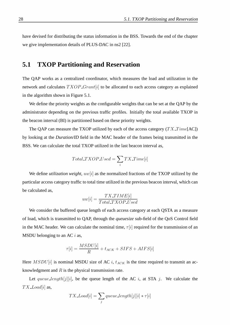
5.1 TXOP Partitioning and Reservation
The QAP works as a centralized coordinator, which measures the load and utilization in the
network and calculatesTXOP Grant[i] to be allocated to each access category as explained
in the algorithm shown in Figure 5.1.
We define the priority weights as the configurable weights that can be set at the QAP by the
administrator depending on the previous traffic profiles. Initially the total available TXOP in
the beacon interval (BI) is partitioned based on these priority weights.
The QAP can measure the TXOP utilized by each of the access category (TX Time[AC])
by looking at theDuration/ID field in the MAC header of the frames being transmitted in the
BSS. We can calculate the total TXOP utilized in the last beacon interval as,
Total TXOP Used =∑
i
TX Time[i]
We defineutilization weight,uw[i] as the normalized fractions of the TXOP utilized by the
particular access category traffic to total time utilized inthe previous beacon interval, which can
be calculated as,
uw[i] =TX TIME[i]
Total TXOP Used
We consider the buffered queue length of each access category at each QSTA as a measure
of load, which is transmitted to QAP, through thequeuesizesub-field of the QoS Control field
in the MAC header. We can calculate the nominal time,τ [i] required for the transmission of an
MSDU belonging to an ACi as,
τ [i] =MSDU [i]
R+ tACK + SIFS + AIFS[i]
HereMSDU [i] is nominal MSDU size of ACi, tACK is the time required to transmit an ac-
knowledgment andR is the physical transmission rate.
Let queue length[j][i], be the queue length of the ACi, at STA j. We calculate the
TX Load[i] as,
TX Load[i] =∑
j
queue length[j][i] ∗ τ [i]

5.1. TXOP Partitioning and Reservation 29
1: calculate utilization weights();
/* fraction of time used by particular access category to total time utilized in the previous beacon
interval
uw[i] = TX TIME[i]Total TXOP Used
*/
2: Total TXOP Available=Timein CP - TotalTXOP Used
3: calculate load weights();
/* fraction of time required for queue length of particular access category to total time required by
the queues as measured by Access Point
lw[i] = TX Load[i]Total TXOP Needed
*/
4: if Total TimeNeeded is Zerothen
5: for Each Access Categorydo
6: TXOP Grant[i]=Total TXOP Available * pw[i]
/* pw[i] is the priority weight of the Access Category, fraction of time reserved by the policy
controller.
*/
7: end for
8: else
9: for Each Access Categorydo
10: ew[i] = pw[i] ·
(
0.5 + α · lw[i]
1 + α · uw[i]
)
11: TXOP Grant[i] = Total TXOP Available ∗ ew′[i]
/* ew′[i] is the normalized effective weight. */
12: end for
13: end if
Figure 5.1: TXOP Grant Calculation
The total TXOP needed across ACs can be calculated as,
Total TXOP Needed =∑
i
TX Load[i]
Now, we defineload weight,lw[i] as the normalized fraction of TXOP load of a particular
access category to total TXOP required to service the load asmeasured by the QAP. It can be
calculated as follows.
lw[i] =TX Load[i]
Total TXOP Needed

30 5.2. Distributed Admission Control at each QSTA
Now, theeffective weight,ew[i] of each AC is calculated as a function ofload weight (lw[i]),
utilization weight (uw[i]), andpriority weight (ew[i]) of the AC as,
ew[i] = pw[i] ·
(
0.5 + α · lw[i]
1 + α · uw[i]
)
whereα is thebalance factor, which can be set by the administrator, depending on how much
importance to be given to load in the network. When a particular priority is not using the TXOP
allocated for it, the unused TXOP will be allocated to accesscategories which have enough
load (indicated by a higherlw[i]), but not utilized the channel optimally (indicated by lower
uw[i]) in the last beacon interval. The increase in theα value, enhances this effect. During
initialization, the entire TXOP is partitioned based on thepriority weights. As and when new
flows come into the network thelw[i] of medium and low priority traffic will increase, resulting
in an increase inew[i]. When the medium and low priority traffic are getting sufficient TXOP,
which can be indicated by the increased uw[i] values, again more weight will be given to high
priority traffic. The value0.5 in the numerator indicates that approximately50% weight will be
given to priority even when the load in the network is negligible.
We estimate theTXOP Grant[i] for each ACi at the start of each BI as,
TXOP Grant[i] = Total TXOP Available ∗ ew′[i]
whereew′[i] is the normalized effective weight. The QAP sends thisTXOP Grant[i] for each
AC i to all the stations as a part of the beacon frame.
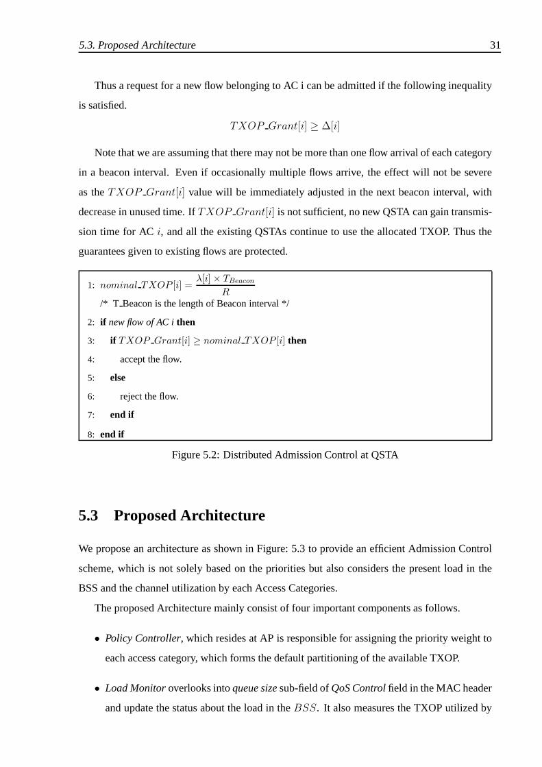
5.2 Distributed Admission Control at each QSTA
Each of the QSTA notes the announcedTXOP Grant at the start of each beacon interval.
When a new flow starts in the present beacon interval, admission control will be done following
the algorithm given inFigure:5.2.
We can estimate∆[i], the nominal TXOP required by a new flow belonging to ACi, from
the Traffic Specification negotiated. The nominal TXOP required for a traffic stream can simply
be calculated as,
∆[i] =λ[i] × TBeacon
R
whereλ[i] is the arrival rate,TBeacon is the length of beacon interval andR is thePHY trans-
mission rate.
5.3. Proposed Architecture 31
Thus a request for a new flow belonging to AC i can be admitted ifthe following inequality
is satisfied.
TXOP Grant[i] ≥ ∆[i]
Note that we are assuming that there may not be more than one flow arrival of each category
in a beacon interval. Even if occasionally multiple flows arrive, the effect will not be severe
as theTXOP Grant[i] value will be immediately adjusted in the next beacon interval, with
decrease in unused time. IfTXOP Grant[i] is not sufficient, no new QSTA can gain transmis-
sion time for ACi, and all the existing QSTAs continue to use the allocated TXOP. Thus the
guarantees given to existing flows are protected.
1: nominal TXOP [i] =λ[i] × TBeacon
R
/* T Beacon is the length of Beacon interval */
2: if new flow of AC ithen
3: if TXOP Grant[i] ≥ nominal TXOP [i] then
4: accept the flow.
5: else
6: reject the flow.
7: end if
8: end if
Figure 5.2: Distributed Admission Control at QSTA
5.3 Proposed Architecture
We propose an architecture as shown in Figure: 5.3 to providean efficient Admission Control
scheme, which is not solely based on the priorities but also considers the present load in the
BSS and the channel utilization by each Access Categories.
The proposed Architecture mainly consist of four importantcomponents as follows.
• Policy Controller, which resides at AP is responsible for assigning the priority weight to
each access category, which forms the default partitioningof the available TXOP.
• Load Monitoroverlooks intoqueue sizesub-field ofQoS Controlfield in the MAC header
and update the status about the load in theBSS. It also measures the TXOP utilized by

32 5.4. Implementation Details
Beacon
(Q)STA
Scheduler
Adaptation Module
802.11e Base Mac
STAController
DistributedAdmission Controller
Admission Control Agent
Access Point
Adaptation Module
Policy controller
802.11e Base MacScheduler
APController
Load Monitor
Wireless Physical Channel
Figure 5.3: Proposed Architecture
each of the AC looking into theDuration/ID field in MAC header of the frames being
transmitted in the BSS.
• Adaptation Moduleforms the core of the architecture, at AP it calculates the amount
to TXOP to be allocated to each access category and informs the Controller, which in
turn sends the information to all the stations through Beacon. At the each of the stations,
Adaptation Modulemakes use of theTXOP Grant sent through the beacon and updates
the local state information.
• Distributed Admission Controllerwill use the updated state information to make decisions
about admission of flows pertaining each access category.
5.4 Implementation Details
In this section we discuss the implementation issues that wefaced and important code details.
We also present the various decisions that we took during implementation and the justifications
for the same.
We have implemented the PLUS-DAC mechanism inns-2 [22]. The FHCF ns-patch [23]
5.4. Implementation Details 33
is extended to support the admission control. A good introduction about various functions of
IEEE 802.11 MAC implementation in ns2 can be found at [24].
5.4.1 Important Changes
Following are the important changes that we had to make to implement PLUS-DAC.
1. Accepted List:
Assuming that there is only one flow of each traffic category ateach, maintaining a simple
boolean array by each STA to check whether a particular category at that node is accepted
or not.
2. Traffic indication:
A boolean array to indicate that the traffic of a particular category has just started arriving
at that station. To differentiate a new flow from existing flows. The admissibility decision
should be made only with respect to new flows.
3. resetTime list:
A list of counters for each of the traffic category, which willbe reset when ever a packet of
that category is sent and decreased at the start of every beacon interval. The counters are
initialized with number of beacon intervals that should be considered before assuming
inactivity. If there is no traffic of a particular category ata station, i.e., the resetTime
counter becomes zero, Traffic indication is changed (Indication of Stop of Flow).
4. Beacon Modifications :
As discussed before, PLUS-DAC sends theTXOP Grant information for all the access
categories is transmitted through beacon. The existing beacon frame is modified to in-
clude an array of 8 fields to carry this information. So the partitioning is based on traffic
categories, rather than access categories.
5. Class DCACController
This class contains all the functionality that we describedin the previous sections. Some
of the important functions that this class contains to carryout the TXOP reservations and
admission control are as follows.

34 5.4. Implementation Details
• check admissible: This function is called from the MAC before sending any packet
on to the channel. The traffic indication is verified to find outit is a new flow.
The admissibility criteria is followed for new flows. For existing flows simply ac-
cepted[AC] is returned. So we achieve admission control by continuously dropping
the packets of rejected flows.
• set priority weights: This function carries out the job of policy controller. The prior-
ity weights are read from configuration file and set accordingly during initialization.
• updateTX Time: As every packet is broadcast and is received by all the stations,
an AP, will update the channel utilization with the estimated time, before discarding
the frame.
• updatequeuelength: The queue length calculations from priority queue are noted
when ever a QoS data or QoS Null packet is received by the MAC. Special care
must be taken for flow having destination not same as AP.

Chapter 6
Simulation and Results
In this chapter we study the performance of PLUS scheme in comparison with a static admission
control scheme and pure EDCA with no admission control. We have implemented the PLUS-
DAC mechanism inns-2 [22]. The FHCF ns-patch [23] is extended to support the admission
control.
The following sections explain about the types of traffic considered for simulation and vari-
ous performance metrics considered to evaluate the schemes. We have considered two scenarios
to test the PLUS-DAC mechanism. In both the scenario we startthe simulation with light load
conditions and increase the load in the network gradually.
6.1 Simulation Setup and Traffic Description
The design of the network we have considered in our simulation follows the conventional ap-
proach as shown in 6.1. Our topology consists of several wireless stations and an access point.
The QAP serves as a direct sink for all the flows from various stations.
AP
Node 1 Node 2 Node n
Figure 6.1: Simulation Setup
35

36 6.1. Simulation Setup and Traffic Description
Each station can have a high priority exponential on-off audio flow (64Kb/s) with 400ms
burst time and600ms idle time, a H.261 VBR video flow(200Kb/s) with medium priority, a
CBR MPEG video flow(3.2Mb/s) with medium priority and a low priority poisson data flow
(1000Kb/s).
We mapped the traffic streams to three access categories: voice (AC 3), video (AC 2), data
(AC 0). We have the following parameters for the traffic streams as described in TABLE 6.1.
Parameters Audio H.261 video MPEG4 video Data
Packet Size (bytes) 160 660 1000 1500
Arrival Period (ms) 4.7 26 2.5 12
Sending rate (Kbps) 64 200 3200 1000
AIFS (µs) 25 25 25 34
CWmin 7 31 31 127
CWmax 15 63 63 1023
Table 6.1: Description of Traffic streams
TheMAC andPHY parameters used for the simulation are given in TABLE 6.2.
Parameters Value
SIFS 16µs
DIFS 34µs
Slot Time 9µs
CCA Time 3µs
Beacon Interval 500ms
PHY Rate 54 Mb/s
Min. bandwidth 24 Mb/s
MAC header 38 bytes
PLCP header 4 bits
Preamble Length 20 bits
Table 6.2: PHY and MAC Parameters

6.2. Performance Metrics Considered 37
6.2 Performance Metrics Considered
We compare the three schemes: 1) pure EDCA, 2) EDCA with static admission control (SDAC),
and 3) EDCA with PLUS-DAC.
In order to evaluate the performance of PLUS-DAC, we have studied latency, bandwidth
characteristics of different kinds of traffic with parameters such as,
• Mean Latency and Jitter: These are the average latency and jitter of all the flows that
have the same priority in the different stations. These metric is used to evaluate how well
the schemes can accommodate real-time flows. Real-time flowsalso require low average
delay and bounded delay jitter.
• Latency distribution and Packet Loss Ratio: Latency distribution allows to trace the per-
centage of packets that have latency less than the maximum delay required by the appli-
cations. Mean packet loss ratio is used to evaluate whether the schemes are performing
satisfactory in case of loss sensitive applications.
• Throughput per stream, and Total throughput: Throughput per stream variation show how
well the accepted flows are protected. The total throughput gives a measure of channel
utilization and the efficiency of the scheme.
For a good quality multimedia service, unidirectional latency should be less than150ms and
packet loss should be less than10%. The LAN component of these requirements should be
more stringent. We can observe from the results that PLUS-DAC performs better and achieves
quasi-optimal channel utilization in various situations.
6.3 High Priority Scenario
In this scenario, only high and medium priority traffic. The goal of this scenario is to show
that PLUS-DAC successfully give QoS guarantees to high priority flows while achieving better
channel utilization. we have 21 station in the network and simulated audio and video traffic
over a duration of 200 seconds. We have 20 audio, 20 H.261 VBR video flows and 15 CBR
video flows.
Audio and VBR flows start at 0 seconds and new flows arrive periodically every 5 seconds
till 50 seconds, then from 50 seconds to 100 seconds there areno new flows, and again from

38 6.3. High Priority Scenario
100 seconds to 150 seconds the flows come in periodically. CBRvideo flows arrive periodically
from 0 seconds to 150 seconds every 10 seconds. The priority weights considered for the
scenario are :pw[3] = 0.7 andpw[2] = 0.3, and the balance factor selected for this scenario is
1;
0
0.5
1
1.5
2
2.5
0 20 40 60 80 100 120 140 160 180 200
late
ncy
(ms)
Simulation Time (sec)
Latency per Stream (Audio)
EDCA SDAC PLUS
0
0.5
1
1.5
2
2.5
3
0 20 40 60 80 100 120 140 160 180 200
jitte
r (m
s)
Simulation Time (sec)
Mean Jitter per Stream (Audio)
EDCA SDAC PLUS
Figure 6.2: Audio latency characteristics
Latency Characteristics Figure 6.2 show the latency characteristics of audio using different
schemes. As we can observe, the latency characteristics of PLUS-DAC and SDAC are almost
similar, and are well with in the QoS limits of the flows(< 0.5ms). Even the latency and jitter
experienced by EDCA alone is not very high (< 3ms), this is because audio flows are of highest
priority and the bandwidth requirements are very less compared to other flows.
0
5
10
15
20
25
30
0 20 40 60 80 100 120 140 160 180 200
late
ncy
(ms)
Simulation Time (sec)
Latency per Stream (Video-VBR)
EDCA SDAC PLUS
0
2
4
6
8
10
12
14
0 20 40 60 80 100 120 140 160 180 200
jitte
r (m
s)
Simulation Time (sec)
Mean Jitter per Stream (Video-VBR)
EDCA SDAC PLUS
Figure 6.3: VBR latency characteristics
As we can observe, from Figure 6.3 in the latency characteristics of VBR traffic also PLUS-
DAC and SDAC perform almost similar. But the latency and jitter experienced by pure EDCA
alone is slightly high (20 − 25ms) compared to admission control schemes.

6.3. High Priority Scenario 39
0
100
200
300
400
500
600
700
0 20 40 60 80 100 120 140 160 180 200
late
ncy
(ms)
Simulation Time (sec)
Latency per Stream (Video-CBR)
EDCA SDAC PLUS
0
2
4
6
8
10
12
14
0 20 40 60 80 100 120 140 160 180 200
jitte
r (m
s)
Simulation Time (sec)
Mean Jitter per Stream (Video-CBR)
EDCA SDAC PLUS
Figure 6.4: CBR latency characteristics
Figure 6.4 show the latency characteristics of CBR traffic. Once again, PLUS-DAC and
SDAC perform almost similar. But we can observe that EDCA is completely unacceptable for
MPEG video transmissions, since mean latency is crossing 100ms and gradually increasing.
However the jitter characteristics are not severe as the traffic is CBR.
0
0.01
0.02
0.03
0.04
0.05
0.06
0.07
0 20 40 60 80 100 120 140 160 180 200
pac
ket l
oss
ratio
Simulation Time (sec)
Packet Loss Ratio (Audio)
EDCA SDAC PLUS
0
10
20
30
40
50
60
70
80
90
100
0 2 4 6 8 10 12 14 16 18
% o
f pac
kets
latency (ms)
Latency Distribution (Audio)
EDCA SDAC PLUS
Figure 6.5: Audio packet loss and latency distribution
Packet Loss Ratio and Latency Distribution Figure 6.5 show that audio traffic hardly ex-
perienced any packet losses and we can observe from the latency distribution that the maximum
latency experienced is very less (1̃0ms). Figure 6.6 show that PLUS-DAC and SDAC similar
characteristics. Even EDCA has95% of the packets experiencing a delay less than50ms for
H.261 traffic. But for MPEG video traffic having significant bandwidth requirements EDCA is
not acceptable as we can observe from Figure 6.7. We can also observe that both the admission
control schemes perform similar.

40 6.3. High Priority Scenario
0
0.001
0.002
0.003
0.004
0.005
0.006
0.007
0.008
0.009
0 20 40 60 80 100 120 140 160 180 200
pac
ket l
oss
ratio
Simulation Time (sec)
Packet Loss Ratio (Video-VBR)
EDCA SDAC PLUS
0
10
20
30
40
50
60
70
80
90
100
0 50 100 150 200 250 %
of P
acke
ts
latency (ms)
Latency Distribution (Video-VBR)
EDCA SDAC PLUS
Figure 6.6: VBR packet loss and latency distribution
0
0.1
0.2
0.3
0.4
0.5
0.6
0.7
0.8
0 50 100 150 200
Pac
ket L
oss
Rat
io
Simulation Time (sec)
Packet Loss Ratio (Video-CBR)
EDCA SDAC PLUS
0
10
20
30
40
50
60
70
80
90
100
0 100 200 300 400 500 600 700 800 900 1000
% o
f pac
kets
latency (ms)
Latency Distribution (Video-CBR)
EDCA SDAC PLUS
Figure 6.7: CBR packet loss and latency distribution

6.3. High Priority Scenario 41
0
0.005
0.01
0.015
0.02
0.025
0.03
0.035
0.04
0.045
0 20 40 60 80 100 120 140 160 180 200
thro
ughp
ut (
Mbp
s)
Simulation Time (sec)
Throughput per Stream (Audio)
EDCA SDAC PLUS
0
0.1
0.2
0.3
0.4
0.5
0.6
0 20 40 60 80 100 120 140 160 180 200
thro
ughp
ut (
Mbp
s)
Simulation Time (sec)
Total Throughput (Audio)
EDCA SDAC PLUS
Figure 6.8: Audio throughput characteristics
0.05
0.1
0.15
0.2
0.25
0.3
0.35
0 20 40 60 80 100 120 140 160 180 200
thro
ughp
ut (
Mbp
s)
Simulation Time (sec)
Throughput per Stream (Video-VBR)
EDCA SDAC PLUS
0
0.5
1
1.5
2
2.5
3
3.5
4
4.5
5
0 20 40 60 80 100 120 140 160 180 200
thro
ughp
ut (
Mbp
s)
Simulation Time (sec)
Total Throughput (Video-VBR)
EDCA SDAC PLUS
Figure 6.9: VBR throughput characteristics
0
1
2
3
4
5
0 20 40 60 80 100 120 140 160 180 200
thro
ughp
ut (
Mbp
s)
Simulation Time (sec)
Throughput per Stream (Video-CBR)
EDCA SDAC PLUS
0
2
4
6
8
10
12
14
16
18
20
0 20 40 60 80 100 120 140 160 180 200
thro
ughp
ut (
Mbp
s)
Simulation Time (sec)
Total Throughput (Video-CBR)
EDCA SDAC PLUS
Figure 6.10: CBR throughput characteristics
Throughput Characteristics As we can see from Figure 6.8, the schemes hardly differ in
their throughput characteristics. For VBR traffic, Figure 6.9 shows that PLUS-DAC achieves
better utilization than the SDAC, though there is no difference in per stream throughput, SDAC
accepted only half as many flows as that of PLUS-DAC leading tounder-utilization. As we can

42 6.4. Low priority scenario
observe from Figure 6.10, PLUS-DAC performs far better in case of CBR MPEG flows, which
have significant bandwidth requirements. The throughput per stream in case of EDCA drops
rapidly at low load conditions itself. SDAC has admitted only one CBR flow leading to under
utilization of the channel, whereas PLUS-DAC admitted fourflows achieving better channel
utilization, while still meeting the latency requirementssimilar to SDAC.
0
0.2
0.4
0.6
0.8
1
0 20 40 60 80 100 120 140 160 180 200
ew[i]
Simulation Time (sec)
Effective Weight
AudioVideo(VBR)
Video (CBR)
0
2
4
6
8
10
12
14
16
18
20
22
0 20 40 60 80 100 120 140 160 180 200
thro
ughp
ut (
Mbp
s)
Simulation Time (sec)
Total Throughput
EDCA SDAC PLUS
Figure 6.11: Variation ofew[i] and Total throughput
ew[i] variation As we can observe from Figure 6.11, the ew[i] value for voice is slightly
decreased and gradually became constant giving importanceto priority. In case of CBR video
the value increased with increase in the load and stabilizedonce it accepted enough flows, re-
sulting in better utilization of the channel. As for VBR flows, the requirement and priority
weights are both low, ew[i] is almost constant. We can observe that total throughput achieved
by PLUS-DAC is almost three times that of SDAC. This result isbecause CBR traffic has sig-
nificant bandwidth requirements and reflects the total throughput. Through total throughput of
EDCA also seem higher, it is not useful as the multimedia flowscan not tolerate the latency and
packet loss experienced. PLUS-DAC achieved better channelutilization while simultaneously
guaranteeing the QoS.
6.4 Low priority scenario
In this scenario, we replace VBR traffic with poisson data traffic. The goal of this scenario
is to show that PLUS-DAC protect from misbehaving low priority flows while still achieving
better channel utilization. we have 31 stations in the network and duration of simulation is 200

6.4. Low priority scenario 43
seconds. We have 20 audio, 15 CBR video flows and 30 data flows.
Audio and at 0 seconds and new flows arrive periodically every5 seconds till 100 seconds.
CBR video flows also start from 0 seconds and new flows arrive periodically every 10 seconds
till 100 seconds. Both these categories stabilize after 100ms at 20 and 10 flows respectively.
Three Data flows will arrive at 0, 5 and 10 seconds respectively. Then from 100 seconds to
145 seconds the data flows come in periodically at a rate of 3 flows for 5 seconds. Again from
155 seconds the data flows start leaving the network with the same rate. The priority weights
considered for the scenario are :pw[3] = 0.7 pw[2] = 0.2 andpw[0] = 0.1, and the balance
factor selected for this scenario is1;
0
0.2
0.4
0.6
0.8
1
1.2
1.4
1.6
1.8
0 20 40 60 80 100 120 140 160 180 200
late
ncy
(ms)
Simulation Time (sec)
Latency per Stream (Audio)
EDCA SDAC PLUS
0
0.2
0.4
0.6
0.8
1
1.2
1.4
0 20 40 60 80 100 120 140 160 180 200
jitte
r (m
s)
Simulation Time (sec)
Mean Jitter per Stream (Audio)
EDCA SDAC PLUS
Figure 6.12: Audio latency characteristics
0
0.0002
0.0004
0.0006
0.0008
0.001
0.0012
0.0014
0.0016
0.0018
0 20 40 60 80 100 120 140 160 180 200
pac
ket l
oss
ratio
Simulation Time (sec)
Packet Loss Ratio (Audio)
EDCA SDAC PLUS
0
10
20
30
40
50
60
70
80
90
100
0 2 4 6 8 10 12
% o
f pac
kets
latency (ms)
Latency Distribution (Audio)
EDCA SDAC PLUS
Figure 6.13: Audio packet loss and latency distribution
Audio Figure 6.12 show that the jitter and latency experienced by the audio traffic using dif-
ferent schemes are once again well with in the QoS limits. We can observe from Figure 6.13
that even the packet loss experienced is also similar. The maximum latency experienced is very

44 6.4. Low priority scenario
less (10ms). This is because audio flows are of highest priority and the bandwidth require-
ments are very less compared to other flows. Hence the heavy data traffic is not effecting the
audio traffic. This we can attribute to the fact that we are using strict EDCA parameters, with
contention windows not overlapping.
0
50
100
150
200
250
300
0 20 40 60 80 100 120 140 160 180 200
late
ncy
(ms)
Simulation Time (sec)
Latency per Stream (Video-CBR)
EDCA SDAC PLUS
0
1
2
3
4
5
6
0 20 40 60 80 100 120 140 160 180 200
jitte
r (m
s)
Simulation Time (sec)
Mean Jitter per Stream (Video-CBR)
EDCA SDAC PLUS
Figure 6.14: Video latency characteristics
0
0.1
0.2
0.3
0.4
0.5
0.6
0 50 100 150 200
pac
ket l
oss
ratio
Simulation Time (sec)
Packet Loss Ratio (Video-CBR)
EDCA SDAC PLUS
0
10
20
30
40
50
60
70
80
90
100
0 50 100 150 200 250 300 350 400 450
% o
f Pac
kets
latency (ms)
Latency Distribution (Video-CBR)
EDCA SDAC PLUS
Figure 6.15: Video packet loss and latency distribution
Video As we can observe from Figure 6.14, PLUS-DAC gets effected bythe low priority data
traffic, as video traffic is having most of the bandwidth requirements. But the effect is not severe,
we can see from Figure 6.15 that packet loss ratio (≤ 10%) and maximum delay (150ms) are
acceptable. Figure 6.16 show that PLUS-DAC has the best throughput characteristics. We can
observe that per stream throughput is almost similar to SDACand total throughput is almost
four times that of SDAC. PLUS-DAC has admitted eight video flows compared to two flows
admitted by SDAC.

6.4. Low priority scenario 45
1.4
1.6
1.8
2
2.2
2.4
2.6
2.8
3
3.2
3.4
0 20 40 60 80 100 120 140 160 180 200
thro
ughp
ut (
Mbp
s)
Simulation Time (sec)
Throughput per Stream (Video-CBR)
EDCA SDAC PLUS
0
5
10
15
20
25
0 20 40 60 80 100 120 140 160 180 200
thro
ughp
ut (
Mbp
s)
Simulation Time (sec)
Total Throughput (Video-CBR)
EDCA SDAC PLUS
Figure 6.16: Video throughput characteristics
0
1
2
3
4
5
0 20 40 60 80 100 120 140 160 180 200
thro
ughp
ut (
Mbp
s)
Simulation Time (sec)
Throughput per Stream (Data)
EDCA SDAC PLUS
0
2
4
6
8
10
12
0 20 40 60 80 100 120 140 160 180 200
thro
ughp
ut (
Mbp
s)
Simulation Time (sec)
Total Throughput (Data)
EDCA SDAC PLUS
Figure 6.17: Data throughput characteristics
Data As we can see from Figure 6.17, that PLUS-DAC has good per stream throughput, but
the total throughput is less. This is because PLUS-DAC has admitted Video flows by the time
the data flows enter the network.
0
0.2
0.4
0.6
0.8
1
0 20 40 60 80 100 120 140 160 180 200
ew[i]
Simulation Time (sec)
Effective Weight
AudioVideo (CBR)
Data
0
5
10
15
20
25
30
0 20 40 60 80 100 120 140 160 180 200
thro
ughp
ut (
Mbp
s)
Simulation Time (sec)
Total Throughput
EDCA SDAC PLUS
Figure 6.18: Variation ofew[i] and Total throughput

46 6.4. Low priority scenario
ew[i] variation As we can observe from Figure 6.11, the ew[i] value for voice is slightly
decreased and gradually became constant giving importanceto priority. The value of ew[i] for
data traffic remained at constant because though it has load requirements, the priority is less. For
CBR video the value increased with increase in the load and stabilized once it accepted enough
flows. The ew[i] variation is resulting in CBR traffic stealing the unused bandwidth from audio
traffic. We can observe that PLUS-DAC achieves the highest throughput. PLUS-DAC results in
better optimal channel utilization than SDAC. PLUS-DAC is also successful in protecting the
admitted flows in an acceptable manner.

Chapter 7
Conclusion and Future Research
In this work we have evaluated the performance of distributed admission control based on the
upcoming IEEE 802.11e standard. We have shown that admission control is necessary to sup-
port real time traffic and given an overview of the features that can be used to support admission
control in IEEE 802.11e standard. Our simulation results have shown that TXOP reservation
and attention to load in the network are necessary. PLUS-DACis able to achieve significant im-
provement in the channel utilization while satisfying the QoS guarantees of the real time traffic
simultaneously.
The best thing about PLUS-DAC is that it strictly follows IEEE 802.11e with minimal over-
heads. PLUS-DAC is also compatible with schemes adapting EDCA Parameters. The policing
and scheduling of packets at each station can be done by deferring the channel access to misbe-
having flows in a manner similar to that of virtual collision.
PLUS-DAC presently work with only EDCA, which can be extended to integrate with HCF
controlled channel access (HCCA). EDCA performs better at low load, but as the load in the
network increases the collisions between back-off entities increases resulting in congestion.
HCF may introduces delays at low load, but it performs more steadily at medium to high load
conditions. The architecture suggested in PLUS-DAC can be used to measure the load in the
BSS and switch from EDCA to HCCA once the load crosses a certain threshold.
In an Integrated Scheme for both EDCA and HCCA, the time left in any service interval can
be reallocated to flows basically using EDCA but require the TXOP by explicitly polling them
using HCCA.
PLUS-DAC is a first step towards adapting the TXOP reservation based on load and utiliza-
tion. The algorithm needs to refined further. The policy controller can be enhanced to support
various admission control policies. More over the scheme needs to extended to multi BSS
scenario, and to incorporate mobility.
47


Bibliography
[1] Wireless LAN Medium Access Control(MAC) and Physical Layer(PHY) Specification,
August 1999. ANSI/IEEE Std 802.11, 1999 edition.
[2] Medium Access Control(MAC) and Quality of Service Enhancements, August 2004.
Amendment to ANSI/IEEE Std 802.11, 1999 (2003 Reaff) edition.
[3] S. Mangold, S. Choi, P. May, O. Klein, G. Hiertz, and L. Stibor. IEEE 802.11e Wireless
LAN for Quality of Service (invited paper). InProceedings of the European Wireless,
volume 1, pages 32–39, Florence, Italy, February 2002.
[4] S. Mangold. Analysis of IEEE 802.11e and Application of Game Models for Support of
Quality-of-Service in Coexisting Wireless Networks. PhD thesis, RWTH Aachen, June
2003.
[5] Yang Xiao. Enhanced DCF of IEEE 802.11e to Support QoS. InProceedings of IEEE
WCNC, 2003.
[6] Pierre Ansel, Qiang Ni, and Thierry Turletti. An Efficient Scheduling Scheme for IEEE
802.11e. InProceedings of IEEE Workshop on Modeling and Optimization in Mobile, Ad
Hoc and Wireless Networks, 2004.
[7] Lamia Romdhani, Qiang Ni, and Thierry Turletti. Adaptive EDCF: Enhanced Service
Differentiation for IEEE 802.11 Wireless Ad Hoc Networks. In Proc. IEEE WCNC, 2003.
[8] Liqiang Zhang and Sherali Zeadally. HARMONICA: Enhanced QoS Support with Ad-
mission Control for IEEE 802.11 Contention-based Access. In 10th IEEE Real-Time and
Embedded Technology and Applications Symposium, 2004.
49

[9] Yang Xiao and Haizhon Li. Voice and Video Transmissions with Global Data Parameter
Control for the IEEE 802.11e Enhance Distributed Channel Access. InIEEE Transactions
on Parallel and Distributed Systems, 2004.
[10] Balasubramanian Appiah Venkatakrishnan and S.Selvakennedy. An Enhanced HCF for
IEEE 802.11e Wireless Networks. InMSWiM’04.
[11] Antonio Grilo, Mario Macedo, and Mario Nunes. A Scheduling Algorithm for QoS Sup-
port in IEEE 802.11e Networks.IEEE Wireless Communications, 2003.
[12] Antonio Grilo and Mario Nunes. Performance Evaluationof IEEE 802.11e. InThe 14th
International Symposium on Personal, Indoor and Mobile Radio Communication Pro-
ceedings, 2002.
[13] S. Mangold, S. Choi, P. May, and G. Hiertz. IEEE 802.11e -Fair Resource Sharing
between Overlapping Basic Service Sets. InProceedings of the PIMRC 2002, pages 166–
171, Lisbon, Portugal, September 2002.
[14] Lamia Romdhani, Qiang Ni, and Thierry Turletti. A Survey of QoS Enhancements for
IEEE 802.11 Wireless LAN.Journal of Wireless Communications and Mobile Computing,
2004.
[15] Hua Zhu, Imrich Chlamtac, and B.Prabhakaran. A Survey of Quality of Service in IEEE
802.11 Networks.Journal of Wireless Communications, 2004.
[16] Yang Xiao, Haizhon Li, and Sunghyun Choi. Protection and Guarantee for Voice and
Video Traffic in IEEE 802.11e Wireless LANs. InINFOCOMM, 2004.
[17] Dennis Pong and Tim Moors. Call Admission control for IEEE 802.11 Contention Access
Mechanism. InGLOBECOM, 2003.
[18] Woo-Yong Choi. A Centralized MAC-Level Admission Control Algorithm for Traffic
Stream Services in IEEE 802.11e Wireless LANs.International Journal of Electronics
and Communications, 2004.
[19] Giuseppe Bianchi. Performacne Analysis of the IEEE 802.11 Distributed Coordination
Function.IEEE Journal on Selected Areas in Communications, Vol. 18, March 2000.

[20] C. Beard Cory and Frost S. Victor. Connection AdmissionControl for Differentiating
Priority Traffic on Public Networks. InIEEE Military Communications International
Symposium, November 1999.
[21] C. Beard Cory and Frost S. Victor. Prioritized ResourceAllocation for Stressed Networks.
IEEE/ACM Transactions on Networking, 2001.
[22] The Network Simulator - ns2. url:http://www.isi.edu/nsnam/ns/ .
[23] The IEEE 802.11e FHCF Patch. url:http://www-sop.inria.fr/planete/
qni/fhcf/ .
[24] 802.11 MAC code in NS-2 by Joshua Robinson. url:http://www-ece.rice.edu/
˜jpr/802_11.html .


![Adaptive unequal protection for wireless video ...eng.usf.edu/~nghani/papers/mtas2014.pdf · IEEE 802.11e standard [9] enhances the traditional IEEE 802.11 MAC standard to support](https://img.pdfslide.us/doc/110x75/5fa7f8993820fb0a40282a28/adaptive-unequal-protection-for-wireless-video-engusfedunghanipapers-.jpg)
![Performance Analysis of IEEE 802.11e EDCA with QoS ......The enhanced distributed channel access (EDCA) protocol of the emerging IEEE 802.11e standard [5] supports access category](https://img.pdfslide.us/doc/110x75/60b0104527d5601cea74f490/performance-analysis-of-ieee-80211e-edca-with-qos-the-enhanced-distributed.jpg)