Embed Size (px)
Citation preview

CEU
251
Plumbing Fixtures
Continuing Education from the American Society of Plumbing Engineers
September 2017
ASPE.ORG/ReadLearnEarn
Plumbing fixtures are designed for specific functions to maintain public health and sanitation, such as discharging potable water or carrying away waste. Common plumbing fixtures include water closets, urinals, showers, bathtubs, faucets, drinking fountains, bidets, floor drains, and emergency showers. Fixtures are connected to the plumbing system piping by different types of fittings that help regulate flow or perform some other function to ensure that the fixture and the entire system work properly.
FIXTURE MATERIALSThe surface of a plumbing fixture must be smooth, impervious, and easily cleanable to maintain a high level of sanitation. Common plumbing fixture materials include the following.
Vitreous ChinaThis is a unique, extremely strong material that is specially suited to plumbing fixtures. Unlike other ceramic materials, vitreous china does not absorb water because it is not porous. Because vitreous china is nonporous, it has a very high shrinkage rate when fired in a kiln, which accounts for the slight differences among otherwise identical plumbing fixtures.
Exposed vitreous china plumbing fixture surfaces are typically glazed, which provides an appealing finish that can be easily cleaned. However, the glazing is not required to keep the fixture watertight. The glazing of a vitreous china fixture also provides the color of the fixture. Vitreous china is a common fixture material for water closets, urinals, bidets, drinking fountains, sinks, and lavatories.
Nonvitreous ChinaNonvitreous china is a porous ceramic that requires glazing to prevent water absorption. The advantage of nonvitreous china is its low shrinkage rate, which allows the fixture to be more ornately designed. Nonvitreous china typically is used for sinks and lavatories.
Enameled Cast IronThe base of enameled cast iron fixtures is a high-grade cast iron. The exposed surfaces have an enameled coating, which is fused to the cast iron, resulting in a hard, glossy, opaque, and acid-resistant surface. Enameled cast iron plumbing fixtures are heavy, strong, ductile, and long lasting. Fixtures made of enameled cast iron include sinks, lavatories, bathtubs, and showers.
Porcelain Enameled SteelPorcelain enameled steel is created by bonding porcelain enamel, a substantially vitreous or glossy inorganic coating, to sheet steel by fusion. Porcelain enameled steel is used for bathtubs and showers.
Stainless SteelMany types of stainless steel are used to produce plumbing fixtures, including 316, 304, 302, 301, 202, 201, and 430. One of the key ingredients in stainless steel is nickel, and a higher nickel content tends to produce a better finish in the stainless steel. Higher nickel content also produces a shinier surface. Types 302 and 304 have 8 percent nickel, and Type 316 has 10 percent nickel. Any fixture can be made with stainless steel; however, the most common use of stainless steel is for sinks and drinking fountains. Stainless steel water closets and urinals are used for severe service such as in highway rest areas and correctional facilities.
PlasticPlastic is a generic category for a variety of synthetic materials used in plumbing fixtures. The various plastic materials used to produce plumbing fixtures include acrylonitrile butadiene styrene (ABS), polyvinyl chloride (PVC), gel-coated fiberglass-reinforced plastic (FRP), acrylic, cultured marble, cast-filled fiberglass, polyester, cast-filled acrylic, gel-coated plastic, cultured marble acrylic, and acrylic polymer. Plastics used in plumbing fixtures are subject to numerous tests to determine their quality, including the ignition (torch) test, cigarette burn test, stain-resistance test, and chemical-resistance test. The common fixtures made with plastic are bathtubs, showers, whirlpool bathtubs, sinks, and lavatories.
GlassTempered glass fixtures can be ornately designed and are found in numerous designs and colors. Fixtures made with glass are lavatories and sinks.
SoapstoneThis material is used predominantly in the manufacture of laundry trays and service sinks. Soapstone is steatite, which is extremely heavy and very durable.
Reprinted from Plumbing Engineering Design Handbook, Volume 4. © 2016, American Society of Plumbing Engineers. All rights reserved.
Note: In determining your answers to the CE questions, use only the material presented in the corresponding continuing education article. Using information from other materials may result in a wrong answer.
2 Read, Learn, Earn September 2017
READ, LEARN, EARN

TerrazzoThis composite material consists of marble, quartz, granite, glass, or other suitable chips sprinkled or poured with a ce-mentitious chemical or combination binder. It is cured, ground, and polished to a smooth finish to produce a uniformly tex-tured surface. Fixtures made with terrazzo are sinks, lavatories, and service sinks.
Solid SurfaceSolid surface is a nonporous, low-maintenance material that can mimic the appearance of granite, marble, stone, and other naturally occurring materials. Solid surface is manufactured by mixing acrylic, epoxide, or polyester resin with powdered bauxite filler and pigments. In a residential setting, solid surface can be used as kitchen countertops, bathroom vanity tops, and shower and tub surrounds.
APPLICABLE STANDARDSPlumbing fixtures are regulated by consensus standards, which specify materials, fixture designs, and testing requirements. The standard writing organizations in the United States and Canada have made a cooperative effort to coordinate standards, and many newer standards have been harmonized.
While standards for plumbing fixtures are considered voluntary, the requirements become mandatory when they are referenced in plumbing codes and a plumbing code is adopted by a state, province, or local jurisdiction. Most fixture manufacturers enlist a third-party testing laboratory to certify their products as being in conformance with the applicable standard. Model plumbing codes, including the Uniform Plumbing Code (UPC), International Plumbing Code (IPC), National Plumbing Code of Canada, and National Standard Plumbing Code require third-party testing and certification of plumbing fixtures.
Table 1-1 identifies the most common consensus standards regulating plumbing fixtures. A complete list of standards can be found in Plumbing Engineering Design Handbook, Volume 1, Chapter 2.
AccessibilitySeveral federal and plumbing industry codes and standards require certain plumbing fixtures to be accessible to people with disabilities. The standards refer to these fixtures as handicapped fixtures. The federal law regulating accessibility is the Americans with Disabilities Act (ADA) Standards for Accessible Design. Accessibility standards also are found in ICC A117.1: Accessible and Usable Buildings and Facilities. More informa-tion about accessibility requirements can be found in Plumbing Engineering Design Handbook, Volume 1, Chapter 6.
WATER CLOSETSHistorically, water closets (WCs) were identified by the style and type of flush. The terms used were blowout, siphon jet, washout, reverse trap, and washdown. With the passage of the Energy Policy Act of 1992 (EPAct), manufacturers changed the way water closets were designed. Some manufacturers continue to use the terms blowout and siphon jet; however, modern blowout and siphon jet water closets are not similar to those made prior to the adoption of the EPAct.
The EPAct imposed a maximum flushing rate of 1.6 gallons per flush (gpf) for water closets, which was a significant decrease in the amount of water used to flush a water closet. Even lower flow rates are becoming more common, such as ultra-low-flow WCs, which flush as little as 0.4 gpf. Dual-flush WCs give the user the option to flush the full 1.6 gallons for solid waste or one-third less water for liquid waste.
The blowout WC (see Figure 1-1A) operates via a high-velocity direct jet action. In the siphon jet WC (see Figure 1-1B), a jet of water is directed through the trapway to quickly fill the bowl and start the siphonic action immediately upon flushing.
Table 1-1 Plumbing Fixture StandardsPlumbing Fixture Applicable Standard Fixture Material
Water closetsASME A112.19.2/CSA B45.1 China CSA B45.5/IAPMO Z124 PlasticASME A112.19.3/CSA B45.4 Stainless steel
Macerating toilet systems ASME A112.3.4/CSA B45.9 All materials
UrinalsASME A112.19.2/CSA B45.1 ASME A112.19.19 China
CSA B45.5/IAPMO Z124 Plastic
Lavatories
ASME A112.19.1/CSA B45.2 Enameled cast ironASME A112.19.2/CSA B45.1 ChinaASME A112.19.3/CSA B45.4 Stainless steelASME A112.19.1/CSA B45.2 Porcelain enameled steelASME A112.19.2/CSA B45.1 Nonvitreous chinaCSA B45.5/IAPMO Z124 Plastic
Sinks
ASME A112.19.1/CSA B45.2 Enameled cast ironASME A112.19.2/CSA B45.1 ChinaASME A112.19.3/CSA B45.4 Stainless steelASME A112.19.1/CSA B45.2 Porcelain enameled steelASME A112.19.2/CSA B45.1 Nonvitreous chinaCSA B45.5/IAPMO Z124 Plastic
Drinking fountainsASME A112.19.1/CSA B45.2 Enameled cast ironASME A112.19.2/CSA B45.1 ChinaASME A112.19.2/CSA B45.1 Nonvitreous china
Water coolers ARI 1010 All materialsShowers CSA B45.5/IAPMO Z124 Plastic
Bathtubs
ASME A112.19.1/CSA B45.2 Enameled cast ironASME A112.19.1/CSA B45.2 Porcelain enameled steelASME A112.19.2/CSA B45.1 Nonvitreous chinaCSA B45.5/IAPMO Z124 Plastic
BidetsASME A112.19.2/CSA B45.1 ChinaASME A112.19.2/CSA B45.1 Nonvitreous china
Pumped waste fixtures ASME A112.3.4/CSA B45.9 All materialsFloor drains ASME A112.6.3 All materialsEmergency fixtures ISEA Z358.1 All materialsFaucets and fixture fittings ASME A112.18.1/CSA B125.1 All materialsWaste fittings ASME A112.18.2/CSA B125.2 All materials
Figure 1-1 (A) Blowout and (B) Siphon Jet Water Closets
(A) (B)
3 Read, Learn, Earn September 2017
READ, LEARN, EARN: Plumbing Fixtures

Water closets are further categorized as follows:• Close coupled: A two-piece fixture comprised of a separate tank and
bowl (see Figure 1-2A)• One piece: The tank and the bowl are molded as one piece (see Figure
1-2B).• Flushometer: A bowl with a spud connection that receives the connection
from a flushometer valve (see Figure 1-2C). Flushometer water closets also are referred to as top spud or back spud bowls depending on the location of the connection for the flushometer valve.
Water closets are flushed via one of the following methods:• In a gravity flush, used with tank-type water closets, the water is not
under pressure and flushes by gravity.• With a flushometer tank, the water is stored in a pressurized vessel and
flushed under a pressure ranging between 25 and 35 pounds per square inch (psi).
• A flushometer valve uses the water supply line pressure to flush the water closet. Because of the demand for a fast, large-volume flush, the water supply pipe must be larger in diameter than that for gravity or flushometer tank flushes. Flushometer water closets require 35 to 80-psi static pressure and 25 gallons per minute (gpm) to operate properly.
Another distinction used to identify a water closet is the manner of mounting and connection. The common methods are as follows:
• A floor-mounted water closet sits on the floor and connects directly to the piping through the floor.
• Floor-mounted, back-outlet water closets sit on the floor yet connect to the piping through the wall (see Figure 1-3). The advantage of this model is that floor penetrations are reduced.
• A wall-hung water closet is supported by a wall hanger and never comes in contact with the floor (see Figure 1-4). This model is advantageous from a maintenance standpoint because it doesn’t interfere with floor cleaning.
Water Closet Bowl Shape and SizeA water closet bowl is classified as either round or elongated. The front opening of an elongated bowl extends 2 inches farther than a round bowl. Most plumbing codes require elongated bowls for public and employee use. The additional 2 inches provides a larger opening, often called a target area. With the larger opening, the ability to maintain a cleaner water closet for each user is increased.
For floor-mounted water closets, the outlet is identified based on the rough-in dimension, or the distance from the back wall to the center of the outlet when the water closet is installed. A standard rough-in bowl outlet is 12 inches (see Figure 1-5). Most manufacturers also make water closets with a 10-inch or a 14-inch rough-in.
The size of the bowl also is based on the height of the bowl’s rim from the floor, as follows:• The rim height of a standard water closet is 14 to 15 inches. This is the most common water
closet installed.• A child’s water closet has a rim height of 10 inches. Many plumbing codes require these water
closets in day-care centers and kindergarten toilet rooms for use by small children.• A water closet for juvenile use has a rim height of 13 inches.• A handicapped water closet for the physically challenged has a rim height of 17 inches. With the addition of the water closet seat, the
fixture is designed to conform to the accessibility requirement of 17 to 19 inches. These are also called comfort height or chair height and are commonly used in some non-accessible locations.
Bariatric Water ClosetsBariatric water closets are made to accommodate overweight and obese people and support loads of 500 to 1,000 pounds. They are available in vitreous china as well as stainless steel. Wall-hung bariatric fixtures require special, larger carriers designed for the increased load, which also requires a deeper chase. Thus, most bariatric water closets are floor mounted. Bariatric water closets should be mounted at the height required for accessibility.
Water Closet SeatA water closet seat must be designed for the shape of the bowl to which it connects. Two styles of water closet seat are available: solid and open front. Plumbing codes typically require an open front seat for public and employee use. This type of seat helps maintain a higher level of
Figure 1-3 Floor-Mounted, Back-Outlet
Water Closet
Figure 1-4 Wall-Hung Water Closet
Figure 1-2 (A) Close-Coupled, (B) One-Piece,
and (C) Flushometer Water Closets
(A)
(B)
(C)
Figure 1-5 Standard Rough-In Dimension for a Water Closet
Outlet to the Back Wall
Floor flange
12”
4 Read, Learn, Earn September 2017
READ, LEARN, EARN: Plumbing Fixtures

hygiene in public facilities. Many public water closets have a plastic wrap around the seat that can be changed after each use. This seat is intended to replace the open rim seat in public and employee locations.
Water Closet Flushing PerformanceThe flushing performance requirements for water closets are found in ASME A112.19.2/CSA B45.1: Ceramic Plumbing Fixtures, which is a consolidation and revision of several ASME and CSA Group standards developed in response to industry requests for uniform standards that would be acceptable in both the United States and Canada. Previously, the flushing performance requirements were in a separate standard, but the ASME/CSA standards committee believed it was more appropriate to include the testing requirements in the fixture material standard. This standard identifies the following tests that must be performed to certify a water closet:
• The ball removal test utilizes 100 nylon balls that are ¼ inch in diameter. The water closet must flush at least an average of 95 balls on the initial flush of three different flushes. The polypropylene balls are intended to replicate the density of human feces.
• The granule test utilizes approximately 2,500 disc-shaped granules of polyethylene. The initial flush of three different flushes must result in no more than 125 granules on average remaining in the bowl. The granule test is intended to simulate a flush of watery feces (diarrhea).
• The surface wash or ink test is performed on the inside wall of the water closet bowl. A felt-tip marker is used to draw a line around the inside of the bowl. After flushing, no individual segment of line can exceed ½ inch. The total length of the remaining ink line must not exceed 2 inches. This test determines if the water flushes all interior surfaces of the bowl.
• The dye test uses a colored dye added to the water closet’s trap seal. The concentration of the dye is determined both before and after flushing the water closet. A dilution ratio of 100:1 must be obtained for each flush. This test determines the evacuation of urine in the trap seal.
• The mixed media test utilizes 20 polyurethane sponges that are new and dry and 15 sheets of kraft anti-tarnish paper. After the first flush, 23 mixed media pieces must be evacuated from the bowl. After the second flush the remaining media must flush down the drain.
• The water consumption test determines if the water closet meets the federal mandate of 1.6 gpf.• The trap seal restoration test determines that the water closet refills the trap of the bowl after each flush. The remaining trap seal must
be a minimum of 2 inches in depth.• The water rise test evaluates the rise of water in the bowl when the water closet is flushed. The water cannot rise above a point 3 inches
below the top of the bowl.• The backpressure test is used to determine if the water seal remains in place when exposed to a backpressure (from the outlet side of
the bowl) of 2½ inches of water column (wc). This test determines if sewer gas will escape through the fixture when high pressure occurs in the drainage system piping.
• The rim top and seat fouling test determines if the water splashes onto the top of the rim or seat of the water closet. This test ensures that the user does not encounter a wet seat.
• The drainline carry test determines the performance of the water closet’s flush. The water closet is connected to a 4-inch drain 60 feet in length pitched ¼ inch per foot. The media used during the test are 100 polypropylene balls ¾ inch in diameter. The average carry distance of the polypropylene balls must be 40 feet. This test determines the ability of the water closet to flush the contents in such a manner that they properly flow down the drainage piping.
Water Closet Installation RequirementsThe water closet must be properly connected to the drainage piping system. For floor-mounted water closets, a water closet flange is attached to the piping and permanently secured to the building. For wood-frame buildings, the flange is screwed to the floor. For concrete floors, the flange sits on the floor.
Noncorrosive closet bolts connect the water closet to the floor flange. The seal between the floor flange and the water closet is made with either a wax ring or an elastomeric seal. The connection formed between the water closet and the floor is required to be sealed with caulking or tile grout.
For wall-hung water closets, the fixture must connect to a wall carrier. The carrier must transfer the loading of the water closet to the floor. A wall-hung water closet must be capable of supporting a load of 500 pounds at the end of the water closet. When the water closet is connected to the carrier, none of this load can be transferred to the piping system. Water closet carriers must conform to ASME A112.6.1M: Floor Affixed Supports for Off-the-Floor Plumbing Fixtures for Public Use. For bariatric WCs, the loads listed by the manufacturers vary from 650 to 1,000 pounds. These carriers must conform to ASME A112.6.1M as well.
The minimum spacing required for a water closet is 15 inches from the centerline of the bowl to the sidewall and 21 inches from the front of the water closet to any obstruction in front of the water closet (see Figure 1-6). The standard dimension for a water closet compartment is 30 inches wide by 60 inches long. The water closet must be installed in the center of the standard compartment. The minimum distance required between water closets is 30 inches.
Most plumbing codes prohibit the installation of a double sanitary tee or double fixture fitting for back-to-back 1.6-gpf water closets. The minimum spacing required to use a double sanitary tee fitting is 30 inches from the centerline of the water closet outlet to the entrance of the fitting, which rules out a back-to-back water closet connection. The only acceptable fitting is the double combination wye and eighth bend.
Figure 1-6 Water Closet Compartment Spacing Requirements
5 Read, Learn, Earn September 2017
READ, LEARN, EARN: Plumbing Fixtures
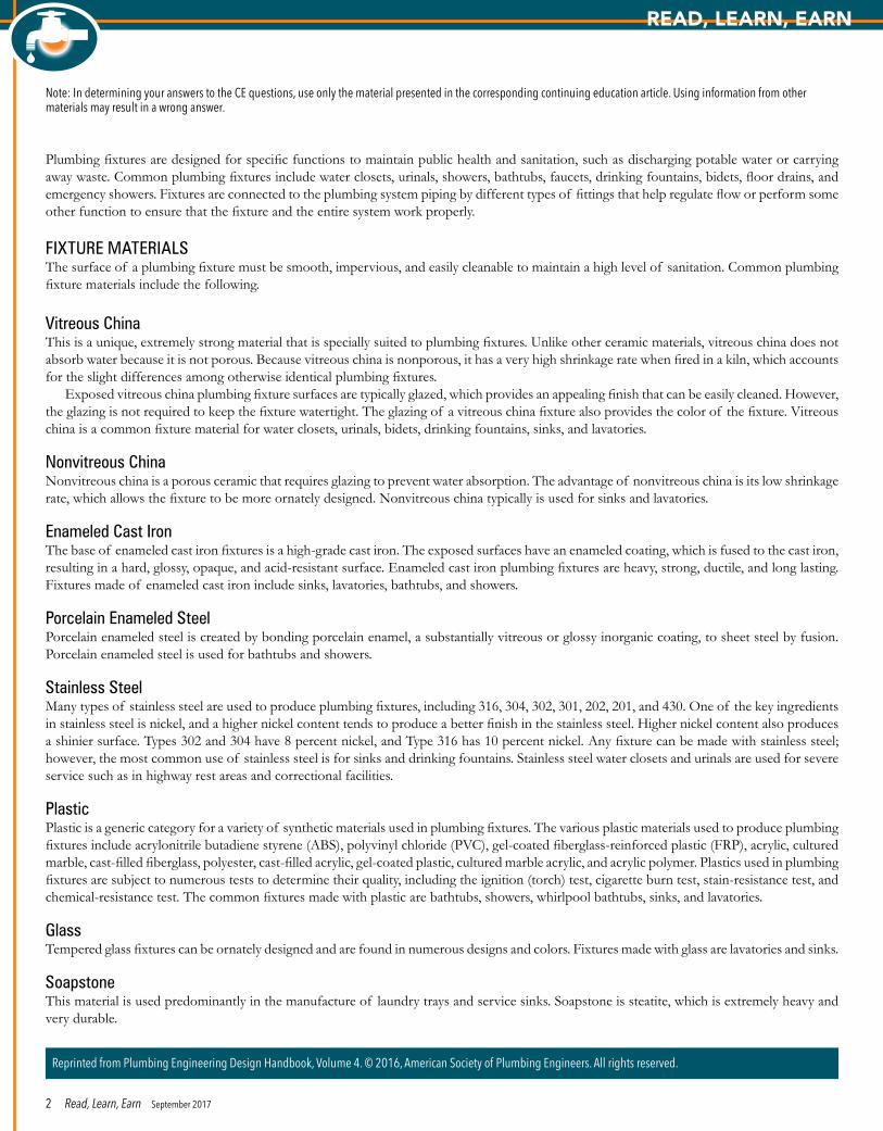
One of the problems associated with short pattern fittings is the siphon action created in the initial flush of the water closet. This siphon action can draw the water out of the trap of the water closet connected to the other side of the fitting. Another potential problem is the interruption of flow when flushing a water closet. The flow from one water closet can propel water across the fitting, interfering with the other water closet.
Proper clearances within chases for wall-hung carriers should be maintained. Figure 1-7 shows the minimum chase sizes for carriers (as published by the Plumbing and Drainage Institute [PDI]). Carrier sizes vary by manufacturer, so always check the manufacturer’s specifications before committing to chase size. Also, wall-hung bariatric carriers require more space than indicated by PDI. Bariatric chases should be coordi-nated with the specified carrier manufacturer.
Water Closet Flushing Systems
Gravity FlushThe most common means of flushing a water closet is the gravity flush (see Figure 1-8A), which is used with tank-type water closets. The tank stores a quantity of non-pressurized water to establish the initial flush of the bowl. A trip lever raises either a flapper or a ball, allowing the flush to achieve the maximum siphon in the bowl. After the flush, the flapper or ball reseals, closing off the tank from the bowl. To achieve the lowest flow in a dual-flush water closet, the trip lever raises the flapper or ball a bit less, which results in a reduced-volume flush.
The ballcock, located inside the tank, controls the flow of water into the tank. A float mechanism opens and closes the ballcock. The ball-cock directs the majority of the water into the tank and a smaller portion of water into the bowl to refill the trap seal. The ballcock must be an anti-siphon ballcock conforming to ASSE 1002/ASME A112.1002/CSA B125.12: Anti-Siphon Fill Valves for Water Closet Tanks. This prevents the contents of the tank from being siphoned back into the potable water supply.
Figure 1-7 Minimum Chase Sizes for Carriers
Horizontal Adjustable Carriers Vertical Adjustable Carriers Vertical Fixed Carriers
Double in metal stud wall Double in metal stud wall Double in metal stud wall
Single in metal stud wall Single in metal stud wall Single in metal stud wall
Double in block wall Double in block wall Double in block wall
Single in block wall Single in block wall Single in block wall
6 Read, Learn, Earn September 2017
READ, LEARN, EARN: Plumbing Fixtures

Flushometer TankA flushometer tank (see Figure 1-8B) has the same outside appearance as a gravity tank. However, inside the tank is a pressure vessel that stores the water for flushing. The water in the pressure vessel must be a minimum of 25 psi to operate properly. Thus, the line pressure on the connection to the flushometer tank must be a minimum of 25 psi. A pressure regulator prevents the pressure in the vessel from rising above 35 psi (typical of most manufacturers).
The higher pressure from the flushometer tank results in a flush similar to a flushometer valve. One of the differences between the flushometer tank and the flushometer valve is the sizing of the water distribution system. The water piping to a flushometer tank is sized the same as the water piping to a gravity flush tank. Typically, the individual water connection is ½ inch in diameter. A flushometer valve requires a high flow rate demand, resulting in a larger piping connection, typically 1 inch in diameter.
The flushometer tank water closet tends to be noisier than the gravity tank water closet. Their advantage over gravity tanks is that the in-creased velocity of the waste stream provides as much as a 50 percent increase in drainline carry. In long horizontal run situations, this means fewer drainline and sewer blockages. Flushometer tanks must conform to ASSE 1037/ASME A112.1037/CSA B125.37: Performance Requirements for Pressurized Flushing Devices for Plumbing Fixtures.
Flushometer ValveA flushometer valve, also referred to as a flush valve, is available in two designs. A diaphragm valve is designed with upper and lower chambers separated by a diaphragm. A piston valve is designed with upper and lower chambers separated by a piston. The water pressure in the upper chamber keeps the valve in the closed position. When the trip lever is activated, the water in the upper chamber escapes to the lower chamber, starting the flush. The flush of 1.6 gallons or less passes through the flush valve, and the valve is closed by line pressure as water reenters the upper chamber.
For 1.6-gpf water closets, flushometer valves are set to flow 25 gpm at the peak flush. The flush-ing cycle is very short, lasting four to five seconds. The water distribution system must be properly designed to allow the peak flow during heavy use of the plumbing system.
Flushometer valves have either a manual or an automatic means of flushing. The most popular manual means of flushing is a handle mounted on the side of the flush valve. The wave-activated flushometer provides manual activation without touching the valve, promoting maximum sanitation. Automatic, electronic sensor flushometer valves are available in a variety of styles. Sensor-operated valves can be battery oper-ated, directly connected to the power supply of the building, or powered by a 30-year hybrid energy system or other eco-friendly power generation system.
Flushometer valves are also available for dual flush. For manual handle valves (see Figure 1-9), moving the handle in one direction, typically downward, results in a full flush, while moving the handle in the opposite direction, typically upward, results in a flush using 30 percent less water. Automatic dual-flush flushom-eter valve actuation bases the flush on the length of time the user is in contact with the flushometer sensor. For short durations, a flush using 30 percent less water is activated. When the water closet is used for a longer period, a full flush is activated.
Macerating Toilet SystemsA water closet can connect to a macerating toilet system when the fixture is located below the drainage piping or if inadequate pitch is available to the gravity drain. A macerating toilet system is a small tank with a grinder pump installed. The water closet connects directly to the tank. When waste enters the tank, the pump activates, grinding the solid and pumping the slurry solu-tion to a gravity drain.
A macerating toilet system can also receive the discharge from a lavatory, shower, or bathtub (see Figure 1-10). Because the tank is installed above the floor, any shower or bathtub would have to be a step-up fixture mounted so the drainage piping is located above the floor.
Figure 1-8 (A) Gravity Tank and (B) Flushometer Tank
Anti-siphon ballcock
Water supply tube Pressure tank
TankRefill tube
Overflow
Float
Flapper
Tank
(A) (B)
Figure 1-9 Manual Dual-Flush Handle
Courtesy of Sloan
Up for liquid waste
Down for solid waste
Figure 1-10 Macerating Toilet SystemCourtesy of Saniflo
Receptacle should be 40” away from bath or shower and ground fault protected.
Bathtub
2” x 8’ (2” x 6’ min)
2” drain
1.5” drain
Ball valve
0.25” – 1’
gravity fall
0.25” – 1’ gravity fall
1.5” vent—connect to existing vent system
0.75” or 1” discharge
40”
7 Read, Learn, Earn September 2017
READ, LEARN, EARN: Plumbing Fixtures

A vent is required for the macerating toilet system to allow for the displacement of air in the sealed tank. The drain for the macerating toilet system can be ¾ inch in diameter. The vent is 1¼ inch minimum in diameter.
Macerating toilet systems must conform to ASME A112.3.4/CSA B45.9: Plumbing Fixtures with Pumped Waste and Macerating Toilet Systems.
URINALSThe urinal was developed to expedite use of a toilet room. It is designed for the removal of urine and the quick exchange of users. The Energy Policy Act of 1992 restricted urinals to a maximum water use of 1 gpf. For many modern urinals, flushing volumes have been reduced to 0.5 gpf or 0.125 gpf. Another category of urinal is the non-water-supplied urinal. As the name suggests, these urinals do not have a water supply or flush volume.
Urinal StylesUrinals are identified as blowout, siphon jet, washout, stall, washdown, and non-water supplied. A stall urinal is a type of washdown urinal. Blowout, siphon-jet, and washout urinals all have integral traps. Stall and washdown urinals have an outlet to which an external trap is con-nected. Many plumbing codes prohibit the use of stall and washdown urinals in public and employee toilet rooms because of concerns about the ability to maintain a high level of sanitation after each flush. Non-water-supplied urinals are acceptable by every model plumbing code, but are not allowed in all jurisdictions.
The style identifies the type of flushing action in the urinal. Blowout and siphon jet types rely on complete evacuation of the trap. Blowout urinals force the water and waste from the trap to the drain. Siphon jet urinals create a siphon action to evacuate the trap. Washout urinals rely on a water exchange to flush, with no siphon action or complete evacuation of the trapway. Stall and washdown urinals have an external trap. The flushing action is a water exchange; however, it is a less-efficient water exchange than that of a washout urinal.
Urinals with an integral trap must be capable of passing a ¾-inch-diameter ball. The outlet connection is typically 2 inches in diameter. Stall and washdown urinals can have a 1½-inch outlet with an external 1½-inch trap.
Non-water-supplied urinals are used to reduce water consumption. Some non-water-supplied urinals utilize a cartridge filled with a biodegrad-able liquid sealant. A more sanitary option utilizes a trap to contain the biodegradable liquid sealant, eliminating the biohazard of disposing of old cartridges. Urine is heavier than the sealant, so it flows through the cartridge or trap while leaving the sealant intact. According to manufacturer literature, a typical cartridge lasts for 7,000 uses. The cartridge-less system lasts equally long, and the trap must be flushed when the sealant is reinstalled. Due to the lack of water, crystallized urine may accumulate in the waste piping.
Non-water-supplied urinals are inexpensive to install. The waste and vent piping are the same as for conventional urinals, but no water piping is required. The inside walls of the urinal must be washed with a special solution on a periodic basis for proper sanitation.
A hybrid urinal is a non-water-supplied urinal with a water supply. Periodically, typically once a day, a flush of water is activated to clear any urine solids that may accumulate in the piping. The flush can also be manually activated by maintenance personnel.
Urinal Flushing PerformanceThe flushing performance for urinals is regulated by ASME A112.19.2/CSA B45.1. The three tests for urinals are the ink test, dye test, and water consumption test.
In the ink test, a felt-tip marker is utilized to draw a line on the inside wall of the urinal. The urinal is flushed, and the remaining ink line is measured. The total length of the ink line cannot exceed 1 inch, and no segment can exceed ½ inch in length.
The dye test uses a colored dye to evaluate the water exchange rate in the trap. After one flush, the trap must have a dilution ratio of 100:1 (or 17:1 for high-efficiency urinals). The dye test is performed only on urinals with an integral trap (blowout, siphon jet, and washout urinals). It is not possible to dye test stall and washdown urinals since they have external traps. This is one of the concerns that has resulted in the re-stricted use of these fixtures.
The water consumption test determines if the urinal flushes with 1 gallon of water or less.
Urinal Flushing RequirementsUrinals must be flushed with a flushometer valve, which can be either manually or automatically activated. A urinal flushometer valve has a lower flush volume and flow rate than a water closet flushometer valve. The total volume is 1 gpf or less, and the peak flow rate is 12 gpm. The water distribution system must be properly sized for the peak flow rate of the urinal.
Urinal flushometer valves operate the same as water closet flushometer valves. For additional information, refer back to the “Water Closet Flushing Systems” section.
Urinal Installation RequirementsThe minimum spacing between the centerline of a urinal and the sidewall is 15 inches (see Figure 1-11). The minimum spacing required between urinals is 30 inches center to center. This spacing provides access to the urinal without the user coming in contact with the user of the adjacent fixture. The minimum spacing required in front of the urinal is 21 inches. One plumbing code requires parti-tions between each urinal, which ensures a modicum of privacy. Figure 1-11 Required Urinal
Spacing
8 Read, Learn, Earn September 2017
READ, LEARN, EARN: Plumbing Fixtures

For urinals with an integral trap, the outlet is located 21 inches above the floor for a standard-height installation. Stall urinals are mounted on the floor. Wall-hung urinals must be mounted on carriers that transfer the weight of the urinal to the floor. The carrier also connects the urinal to the waste piping system. Sufficient room should be provided in the chase for the carrier. Figure 1-12 shows the minimum chase sizes recommended by PDI.
Many plumbing codes require urinals for public and employee use to have a visible trap seal. This refers to blowout, siphon jet, and washout urinals.
LAVATORIESA lavatory is a washbasin used for personal hygiene. In public locations, a lavatory is intended to be used for washing one’s hands and face. Residential lavatories are intended for hand and face washing, shaving, applying makeup, cleaning contact lenses, and similar hygienic activities.
Lavatory faucet flow rates are regulated as part of the Energy Policy Act of 1992. The original flow rate established by the government was 2.5 gpm at 80 psi for private-use lavatories and 0.5 gpm, or a cycle discharging 0.25 gallon, for public-use lavatories. Now the regulations require 2.2 gpm at 60 psi for private (and residential) lavatories and 0.5 gpm at 60 psi, or a cycle discharging 0.25 gallon, for public lavatories.
Lavatory faucets are available with electronic valves. These faucets can reduce water usage by supplying water only when hands are inside the bowl.
Lavatory Size and ShapeManufacturers produce lavatories in every conceivable size and shape: square, round, ob-long, rectangular, shaped for corners, with or without ledges, decorative bowls, and molded into countertops.
The standard outlet for a lavatory is 1¼ inches in diameter. The standard lavatory has three holes on the ledge for the faucet. With a typical faucet, the two outside holes are 4 inches apart. The faucets installed in these lavatories are called 4-inch centersets. When spread fau-cets are to be installed, the spacing between the two outer holes is 8 inches.
For many years, fixture standards required lavatories to have an overflow based on the concept that the basin was filled prior to clean-ing. If the user left the room while the lavatory was being filled, the water would not overflow onto the floor. However, studies have shown that lavatories are rarely used in this capacity. It is more common to not fill the basin with water during use. As a result, overflows now are typically an optional item for lavatories, yet some plumbing codes still require them. The minimum cross-sectional area of an overflow is 1⅛ inches.
Another style of lavatory is the circular or semicircular group wash fountain. The plumbing codes consider every 20 inches of space along a group wash fountain to be equivalent to one lavatory.
Lavatory InstallationThe standard height of a lavatory is 31 inches above the finished floor (see Figure 1-13). A spacing of 21 inches is required in front of the lavatory to access the fixture.
Lavatories can be counter mounted, under-counter mounted, or wall hung. When lavatories are wall hung in public and employee facilities, they must be connected to a carrier that transfers the weight of the fixture to the floor. Figure 1-14 shows the minimum chase sizes recommended by PDI.
KITCHEN SINKSA kitchen sink is used for culinary purposes. The two distinct classifications of kitchen sinks are residential and commercial. Residential kitchen sinks can be installed in commercial buildings, typically in kitchens used by employees. Commercial kitchen sinks are designed for restaurant and food-handling establishments.
Figure 1-12 Minimum Chase Sizes for Urinals
Urinal profile view
Urinal with clearance for waste pipe
Figure 1-13 Recommended Installation Dimensions for a Lavatory
31” above floor
Figure 1-14 Minimum Chase Sizes for Lavatories
Hanger Plate Carriers Arm Lavatory Carriers
Lavatory Concealed
Lavatory with clearance for waste pipe
Concealed with clearance for waste
pipeArm Lavatory Carriers
Exposed
Exposed with clearance for waste
pipe
9 Read, Learn, Earn September 2017
READ, LEARN, EARN: Plumbing Fixtures
The Energy Policy Act of 1992 required the flow rate of faucets for residential kitchen sinks to be 2.5 gpm at 80 psi. Fixture standards have since modified the flow rate to 2.2 gpm at 60 psi.
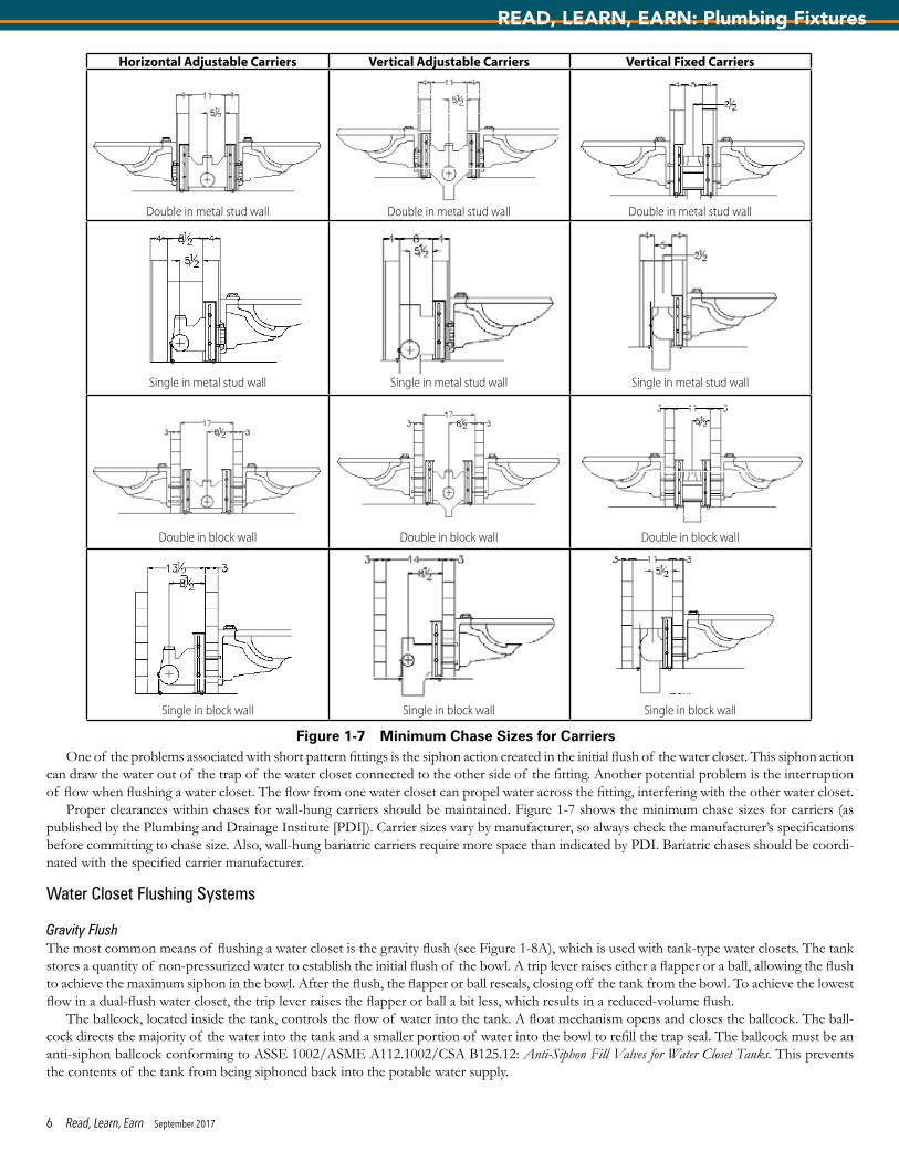
Residential Kitchen SinksCommon residential kitchen sinks are single- or double-compartment (or bowl) sinks. No standard dimension for the size of the sink exists; however, most kitchen sinks are 22 inches measured from the front edge to the rear edge. For single-compartment sinks, the most common width of the sink is 25 inches. For double-compartment kitchen sinks, the most common width is 33 inches. The common depth of the com-partments is 9 to 10 inches. Accessible sinks are 5.5 to 6.5 inches deep.
Some specialty residential kitchen sinks have three compartments. Typically, the third compartment is smaller and does not extend the full depth of the other compartments.
Most plumbing codes require the outlet of a residential kitchen sink to be 3½ inches in diameter. This is to accommodate the installation of a food waste grinder.
Kitchen sinks have one, three, or four holes for the installation of the faucet. Some single-lever faucets require only one hole for installation. The three-hole arrangement is for a standard two-handle valve installation. The four-hole arrangement is designed to allow the installation of a side spray or other kitchen appurtenance such as a soap dispenser.
The standard installation height for a residential kitchen sink is 36 inches above the finished floor (see Figure 1-15). Most architects tend to follow the 6-foot triangle rule when locating a kitchen sink. The sink is placed no more than 6 feet from the range and 6 feet from the refrigerator.
Residential kitchen sinks mount either above or below the counter. Counter-mounted kitchen sinks are available with a self-rimming ledge or a sink frame.
Commercial Kitchen SinksCommercial kitchen sinks are typically larger in size and have a deeper bowl than residential kitchen sinks. The depth of the bowl typically ranges from 16 to 20 inches. Commercial kitchen sinks are often freestanding sinks with legs for support. Because of health authority requirements, most commercial kitchen sinks are stainless steel.
In commercial kitchens, three types of sinks typically are provided: hand sinks, prep sinks, and triple-basin sinks. Prep sinks usually are a single basin used in con-junction with food preparation. Triple-basin sinks are used for washing pots, pans, and utensils.
Health authorities require either a two- or three-compartment sink in every com-mercial kitchen. The requirement for a three-compartment sink dates back to the use of the first compartment for dishwashing, the second compartment for rinsing the dishes, and the third compartment for sanitizing the dishes. With the increased use of dishwashers in commercial kitchens, some health codes have modified the requirements for a three-compartment sink.
Commercial kitchen sinks used for food preparation are required to connect to the drainage system through an indirect waste. This prevents the possibility of contaminating food in the event of a drainline backup resulting from a stoppage in the line.
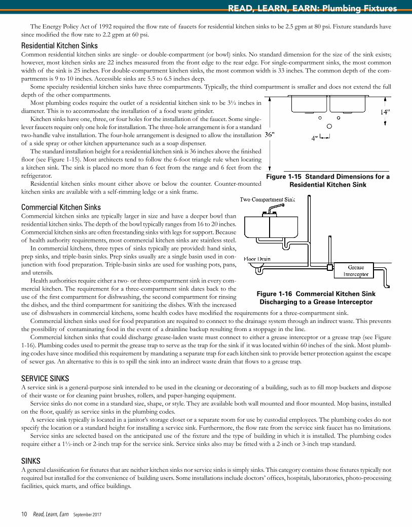
Commercial kitchen sinks that could discharge grease-laden waste must connect to either a grease interceptor or a grease trap (see Figure 1-16). Plumbing codes used to permit the grease trap to serve as the trap for the sink if it was located within 60 inches of the sink. Most plumb-ing codes have since modified this requirement by mandating a separate trap for each kitchen sink to provide better protection against the escape of sewer gas. An alternative to this is to spill the sink into an indirect waste drain that flows to a grease trap.
SERVICE SINKSA service sink is a general-purpose sink intended to be used in the cleaning or decorating of a building, such as to fill mop buckets and dispose of their waste or for cleaning paint brushes, rollers, and paper-hanging equipment.
Service sinks do not come in a standard size, shape, or style. They are available both wall mounted and floor mounted. Mop basins, installed on the floor, qualify as service sinks in the plumbing codes.
A service sink typically is located in a janitor’s storage closet or a separate room for use by custodial employees. The plumbing codes do not specify the location or a standard height for installing a service sink. Furthermore, the flow rate from the service sink faucet has no limitations.
Service sinks are selected based on the anticipated use of the fixture and the type of building in which it is installed. The plumbing codes require either a 1½-inch or 2-inch trap for the service sink. Service sinks also may be fitted with a 2-inch or 3-inch trap standard.
SINKSA general classification for fixtures that are neither kitchen sinks nor service sinks is simply sinks. This category contains those fixtures typically not required but installed for the convenience of building users. Some installations include doctors’ offices, hospitals, laboratories, photo-processing facilities, quick marts, and office buildings.
Figure 1-15 Standard Dimensions for a Residential Kitchen Sink
Figure 1-16 Commercial Kitchen Sink Discharging to a Grease Interceptor
10 Read, Learn, Earn September 2017
READ, LEARN, EARN: Plumbing Fixtures

Sinks come in a variety of sizes and shapes. They don’t have height or spacing requirements, and the flow rate from the faucet is not regulated. Most plumbing codes require a 1½-inch drain connection.
LAUNDRY TRAYSA laundry tray, or laundry sink, is located in the laundry room and is used in conjunction with washing clothes. The sink has either one or two compartments. The depth of the bowl is typically 14 inches. Laundry trays do not come in standard dimensions; however, most single-compartment laundry trays measure 22 inches by 24 inches, and most double-compartment laundry trays measure 22 inches by 45 inches.
Plumbing codes permit a domestic clothes washer to discharge into a laundry tray. The minimum size of the trap and outlet for a laundry tray is 1½ inches.
At one time, laundry trays were made predominantly of soapstone. Today, most laundry trays are plastic. However, stainless steel, enameled cast iron, and porcelain enameled steel laundry trays also are available.
FAUCETSAll sinks and lavatories need a faucet to direct and control the flow of water into the fixture. A faucet performs the simple operations of opening, closing, and mixing hot and cold water. While the process is relatively simple, fixture manufacturers have developed extensive lines of faucets.
Faucet CategoriesFaucets are categorized by application, such as lavatory faucets, residential kitchen sink faucets, laundry faucets, sink faucets, and commercial faucets. The commercial faucet classification includes commercial kitchen faucets and commercial sink faucets. It does not include lavatory fau-cets. All lavatory faucets are classified the same, whether they are installed in a residential or commercial building. It should be noted, however, that some lavatory faucet styles are used strictly in commercial applications. These include self-metering lavatory faucets that discharge a specified quantity of water and electronic lava-tory faucets that operate via sensors. Sensor-operated lavatory faucets can be battery operated, directly connected to the power supply of the building, or powered by a 30-year hybrid energy system or other eco-friendly power generation system.
Faucet Flow RatesThe flow rates for lavatory and noncommercial kitchen faucets are regulated. Table 1-2 identi-fies the flow rate limitations of faucets.
Backflow Protection for FaucetsIn addition to controlling the flow of water, a faucet must protect the potable water supply against backflow. This is often a forgotten require-ment, since most faucets rely on an air gap to provide protection against backflow. When an air gap is provided between the outlet of the faucet and the flood-level rim of the fixture (by manufacturer design), no additional protection is necessary.
Backflow protection becomes a concern whenever a faucet has a hose thread outlet, a flexible hose connection, or a pullout spray connec-tion. For these styles, additional backflow protection is necessary as the hose or hose connection could potentially eliminate the air gap if it is submerged in a nonpotable water source.
The most common form of backflow protection for faucets not having an air gap is the use of a vacuum breaker. Many manufacturers in-clude an atmospheric vacuum breaker in the design of faucets that require additional backflow protection. Atmospheric vacuum breakers must conform to ASSE 1001: Performance Requirements for Atmospheric-Type Vacuum Breakers.
Faucets with pullout sprays or gooseneck spouts can be protected by a vacuum breaker or a backflow system that conforms to ASME A112.18.1/CSA B125.1: Plumbing Supply Fittings. This standard specifies the testing requirements for a faucet to be certified as protecting the water supply against backflow. Pullout spray kitchen faucets also are listed to ASME A112.18.1/CSA B125.1. These faucets have a spout attached to a flexible hose whereby the spout can detach from the faucet body and be used similarly to a side spray.
Side-spray kitchen faucets must have a diverter that ensures that the faucet switches to an air gap whenever the pressure in the supply line decreases. Air gaps are regulated by ASME A112.1.2: Air Gaps in Plumbing Systems (for Plumbing Fixtures and Water-Connected Receptors).
The most important installation requirement is the proper location of the backflow preventer (or the maintenance of the air gap). When atmospheric vacuum breakers are installed, they must be located a minimum distance above the flood-level rim of the fixture, as specified by the manufacturer.
Controlling Hot Water TemperatureThe plumbing codes often regulate the temperature of hot water discharging from a public lavatory. The temperature is typically limited to 110°F. The hot water temperature control (thermostatic mixing) device must conform to ASSE 1070/ASME A112.1070/CSA B125.70: Performance Requirements for Water Temperature Limiting Devices.
DRINKING FOUNTAINSA drinking fountain is designed to provide drinking water to users. The two classifications of drinking fountains are water coolers and drinking fountains. A water cooler has a refrigeration component that chills the water. A drinking fountain is a non-refrigerated water dispenser.
Table 1-2 Faucet Flow Rate Restrictions
Type of Faucet Maximum Flow Rate
Kitchen faucet 2.2 gpm @ 60 psiLavatory faucet 2.2 gpm @ 60 psi
Lavatory faucet, public use 0.5 gpm @ 60 psi
Lavatory faucet, public use, metering 0.25 gallons per cycle
11 Read, Learn, Earn September 2017
READ, LEARN, EARN: Plumbing Fixtures
With the increased use of water bottles, some drinking fountains include a water bottle filler. Stand-alone water bottle filler stations are also available.
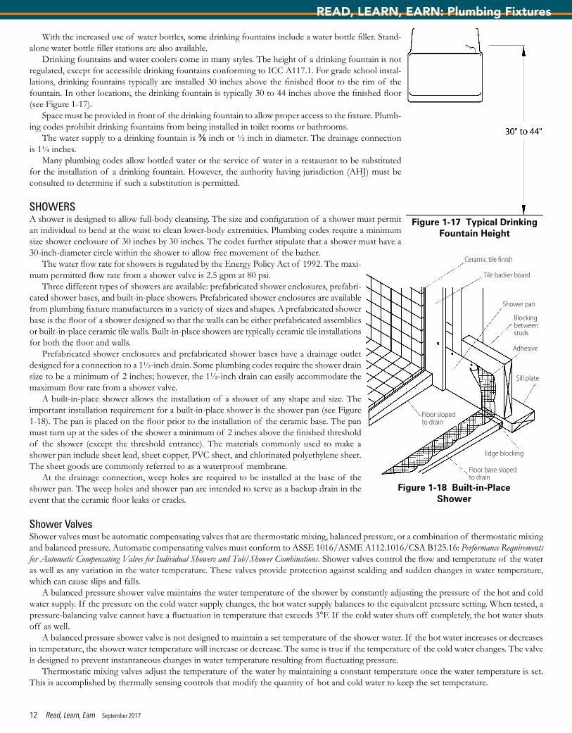
Drinking fountains and water coolers come in many styles. The height of a drinking fountain is not regulated, except for accessible drinking fountains conforming to ICC A117.1. For grade school instal-lations, drinking fountains typically are installed 30 inches above the finished floor to the rim of the fountain. In other locations, the drinking fountain is typically 30 to 44 inches above the finished floor (see Figure 1-17).
Space must be provided in front of the drinking fountain to allow proper access to the fixture. Plumb-ing codes prohibit drinking fountains from being installed in toilet rooms or bathrooms.
The water supply to a drinking fountain is ⅜ inch or ½ inch in diameter. The drainage connection is 1¼ inches.
Many plumbing codes allow bottled water or the service of water in a restaurant to be substituted for the installation of a drinking fountain. However, the authority having jurisdiction (AHJ) must be consulted to determine if such a substitution is permitted.
SHOWERSA shower is designed to allow full-body cleansing. The size and configuration of a shower must permit an individual to bend at the waist to clean lower-body extremities. Plumbing codes require a minimum size shower enclosure of 30 inches by 30 inches. The codes further stipulate that a shower must have a 30-inch-diameter circle within the shower to allow free movement of the bather.
The water flow rate for showers is regulated by the Energy Policy Act of 1992. The maxi-mum permitted flow rate from a shower valve is 2.5 gpm at 80 psi.
Three different types of showers are available: prefabricated shower enclosures, prefabri-cated shower bases, and built-in-place showers. Prefabricated shower enclosures are available from plumbing fixture manufacturers in a variety of sizes and shapes. A prefabricated shower base is the floor of a shower designed so that the walls can be either prefabricated assemblies or built-in-place ceramic tile walls. Built-in-place showers are typically ceramic tile installations for both the floor and walls.
Prefabricated shower enclosures and prefabricated shower bases have a drainage outlet designed for a connection to a 1½-inch drain. Some plumbing codes require the shower drain size to be a minimum of 2 inches; however, the 1½-inch drain can easily accommodate the maximum flow rate from a shower valve.
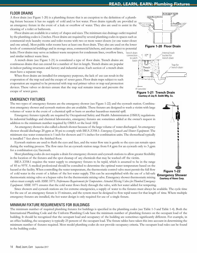
A built-in-place shower allows the installation of a shower of any shape and size. The important installation requirement for a built-in-place shower is the shower pan (see Figure 1-18). The pan is placed on the floor prior to the installation of the ceramic base. The pan must turn up at the sides of the shower a minimum of 2 inches above the finished threshold of the shower (except the threshold entrance). The materials commonly used to make a shower pan include sheet lead, sheet copper, PVC sheet, and chlorinated polyethylene sheet. The sheet goods are commonly referred to as a waterproof membrane.
At the drainage connection, weep holes are required to be installed at the base of the shower pan. The weep holes and shower pan are intended to serve as a backup drain in the event that the ceramic floor leaks or cracks.
Shower ValvesShower valves must be automatic compensating valves that are thermostatic mixing, balanced pressure, or a combination of thermostatic mixing and balanced pressure. Automatic compensating valves must conform to ASSE 1016/ASME A112.1016/CSA B125.16: Performance Requirements for Automatic Compensating Valves for Individual Showers and Tub/Shower Combinations. Shower valves control the flow and temperature of the water as well as any variation in the water temperature. These valves provide protection against scalding and sudden changes in water temperature, which can cause slips and falls.
A balanced pressure shower valve maintains the water temperature of the shower by constantly adjusting the pressure of the hot and cold water supply. If the pressure on the cold water supply changes, the hot water supply balances to the equivalent pressure setting. When tested, a pressure-balancing valve cannot have a fluctuation in temperature that exceeds 3°F. If the cold water shuts off completely, the hot water shuts off as well.
A balanced pressure shower valve is not designed to maintain a set temperature of the shower water. If the hot water increases or decreases in temperature, the shower water temperature will increase or decrease. The same is true if the temperature of the cold water changes. The valve is designed to prevent instantaneous changes in water temperature resulting from fluctuating pressure.
Thermostatic mixing valves adjust the temperature of the water by maintaining a constant temperature once the water temperature is set. This is accomplished by thermally sensing controls that modify the quantity of hot and cold water to keep the set temperature.
Figure 1-17 Typical Drinking Fountain Height
Figure 1-18 Built-in-Place Shower
Ceramic tile finish
Tile backer board
Shower pan
Blocking between studs
Adhesive
Sill plate
Edge blocking
Floor base sloped to drain
Floor sloped to drain
12 Read, Learn, Earn September 2017
READ, LEARN, EARN: Plumbing Fixtures

The maximum flow rate permitted for each shower is 2.5 gpm at 80 psi. If body sprays are added to the shower, the total water flow rate is still 2.5 gpm at 80 psi. A handheld shower spray is considered a showerhead.
The shower valve typically is located 48 to 50 inches above the floor. The installation height for a showerhead ranges from 65 to 84 inches above the floor of the shower. The standard height is 78 inches for showers used by adult males.
BATHTUBSThe bathtub was the original fixture used to bathe or cleanse one’s body. Eventually, the shower was added to the bathtub to expedite the bathing process. The standard installation is a combination tub/shower, but some installations come with a separate whirlpool bathtub and a shower.
Bathtubs tend to be installed within residential units only. The standard bathtub size is 5 feet long by 30 inches wide, with a depth of 14 to 16 inches (see Figure 1-19). How-ever, many different sizes and shapes of bathtubs and whirlpool bathtubs are available. The drain can be either a left-hand (drain hole on the left side as you face the bathtub) or right-hand outlet. Center drains are also available for whirlpool bathtubs. When whirlpool bathtubs are installed, the controls for the whirlpool pump must be accessible.
Bathtubs typically have an overflow drain, which provides protection against overflowing when the bather is not present. Porcelain enameled steel and enameled cast-iron bathtubs are required to have a slip-resistant base to prevent slips and falls. Plastic bathtubs are not required to have the slip-resistant surface since the plastic is considered to have an inherent slip resistance. However, slip resistance can be specified for plastic bathtub surfaces.
Bathtub Fill ValvesThe two types of bathtub fill valves are the tub filler and the combination tub and shower valve. Tub and shower valves must be automatic compensating valves that are balanced pressure, thermostatic mixing, or a combination of balanced pressure and thermostatic mixing valves conforming to ASSE 1016/ASME A112.1016/CSA B125.16 or a thermostatic mixing valve complying with ASSE 1070/ASME A112.1070/CSA B125.70. The tub filler must have a device to control the hot water temperature that complies with ASSE 1070/ASME A112.1070/CSA B125.70. The device can be a separate valve or be integral to the fill valve. The maximum temperature of the hot water for a bathtub is 120°F.
The spout of the tub filler must be properly installed to maintain a 2-inch air gap between the outlet and the flood-level rim of the bathtub. If this air gap is not maintained, the outlet must be protected from backflow by some other means. Certain decorative tub fillers have an atmo-spheric vacuum breaker installed to protect the opening that is located below the flood-level rim.
The standard location of the bathtub fill valve is 14 inches above the top rim of the bathtub. The spout typically is located 4 inches above the top rim of the bathtub to the centerline of the pipe connection.
BIDETSThe bidet is a fixture designed for cleaning the perineal area. The bidet often is mistaken to be a fixture designed for use by the female popula-tion only. However, the fixture is meant for both male and female cleaning. The bidet has a faucet that comes with or without a water spray connection. When a water spray is provided, the outlet must be protected against backflow since the opening is located below the flood-level rim of the bidet. Most manufacturers provide a decorative atmospheric vacuum breaker that is located on the deck of the bidet.
Bidets are vitreous china fixtures that are mounted on the floor. The fixture, being similar to a lavatory, has a 1¼-inch drainage connection. Access must be provided around the bidet to allow a bather to straddle the fixture and sit down on the rim. Most bidets have a flushing rim to cleanse the fixture after each use.
The bidet is used only for external cleansing. It is not designed for internal body cleansing. This often is misunderstood since the body spray may be referred to as a douche (the French word for shower).
The hot water temperature to a bidet must be controlled by a device complying with ASSE 1070/ASME A112.1070/CSA B125.70. The maximum temperature of the hot water for a bidet is 110°F.
PUMPED WASTE FIXTURESA newer category of plumbing fixtures is pumped waste fixtures. A pumped waste fixture can be a lavatory, sink, shower, or bathtub. Each fixture has an individual pump that elevates the waste to a gravity drain. Unlike macerating toilet systems, pumped waste fixtures are not combined with other fixtures. Each pumped waste fixture is a separate fixture.
Pumped waste fixtures allow a fixture to be placed in any location. These fixtures are often used for aging-in-place individuals and physically challenged individuals. The fixture can be added to a floor that did not previously have a bathing fixture.
The manufacturer determines the size of the drain from the pumped waste fixture, but many pumped waste fixtures have a ½-inch-diameter drain. No venting is required for the fixture since the waste is instantly pumped to the gravity drain when the fixture is used.
Figure 1-19 Standard Bathtub
Bathtub fill valve
Overflow
13 Read, Learn, Earn September 2017
READ, LEARN, EARN: Plumbing Fixtures
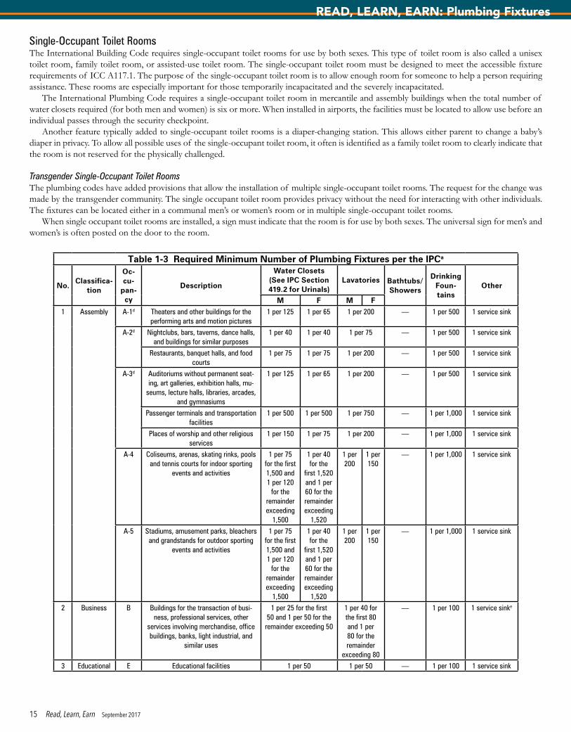
FLOOR DRAINSA floor drain (see Figure 1-20) is a plumbing fixture that is an exception to the definition of a plumb-ing fixture because it has no supply of cold and/or hot water. Floor drains typically are provided as an emergency fixture in the event of a leak or overflow of water. They also are used to assist in the cleaning of a toilet or bathroom.
Floor drains are available in a variety of shapes and sizes. The minimum size drainage outlet required by the plumbing codes is 2 inches. Floor drains are required by several plumbing codes in spaces such as commercial-style laundry rooms and toilet rooms with two or more water closets (or one water closet and one urinal). Most public toilet rooms have at least one floor drain. They also are used on the lower levels of commercial buildings and in storage areas, commercial kitchens, and areas subject to potential leaks. Floor drains may serve as indirect waste receptors for condensate lines, overflow lines, and similar indirect waste lines.
A trench drain (see Figure 1-21) is considered a type of floor drain. Trench drains are continuous drains that can extend for a number of feet in length. Trench drains are popular in indoor parking structures and factory and industrial areas. Each section of a trench drain must have a separate trap.
When floor drains are installed for emergency purposes, the lack of use can result in the evaporation of the trap seal and the escape of sewer gases. Floor drain traps subject to such evaporation are required to be protected with trap seal primer valves or trap seal protection devices. These valves or devices ensure that the trap seal remains intact and prevents the escape of sewer gases.
EMERGENCY FIXTURESThe two types of emergency fixtures are the emergency shower (see Figure 1-22) and the eyewash station. Combina-tion emergency shower and eyewash stations also are available. These fixtures are designed to wash a victim with large volumes of water in the event of a chemical spill or burn or another hazardous material spill.
Emergency fixtures typically are required by Occupational Safety and Health Administration (OSHA) regulations. In industrial buildings and chemical laboratories, emergency fixtures are sometimes added at the owner’s request in addition to the minimum number required by OSHA or the local AHJ.
An emergency shower is also called a drench shower because of the large volume of water discharged. An emergency shower should discharge 20 gpm at 30 psi to comply with ISEA Z358.1: Emergency Eyewash and Shower Equipment. The minimum size water connection is 1 inch for showers and 1¼ inches for combination units. The showerhead typically is installed 7 feet above the finished floor.
Eyewash stations are used to flush the eyes and face, and the water flow rate is gentle so the eyes can remain open during the washing process. The flow rates for an eyewash station range from 0.4 gpm for an eyewash only to 3 gpm for a combination eye/facewash.
Most plumbing codes do not require a drain for emergency showers and eyewash stations to allow greater flexibility in the location of the fixtures and the spot cleanup of any chemicals that may be washed off the victim.
ISEA Z358.1 requires the water supply to emergency fixtures to be tepid, which is assumed to be in the range of 85 to 95°F. A medical professional should be consulted to determine the optimal water temperature based on the hazard at the facility. When controlling the water temperature, the thermostatic control valve must permit the full flow of cold water in the event of a failure of the hot water supply. This can be accomplished with the use of a fail-safe thermostatic mixing valve or a bypass valve for the thermostatic mixing valve. Emergency shower thermostatic mixing valves must comply with ASSE 1071: Performance Requirements for Temperature Actuated Mixing Valves for Plumbed Emergency Equipment. ASSE 1071 ensures that the cold water flows freely through the valve, with hot water added for tempering.
Since showers and eyewash stations are for extreme emergencies, a supply of water to the fixtures must always be available. The cycle time for the use of an emergency fixture is 15 minutes, and the system must be designed to flow tepid water for that length of time. Where multiple emergency fixtures are installed, the hot water design is only required for use of a single fixture.
MINIMUM FIXTURE REQUIREMENTS FOR BUILDINGSThe minimum number of required plumbing fixtures for buildings is specified in the plumbing codes (see Table 1-3 and Table 1-4). Both the International Plumbing Code and the Uniform Plumbing Code base the minimum number of plumbing fixtures on the occupant load of the building. It should be recognized that the occupant load and occupancy of the building are sometimes significantly different. For example, in an office building, the occupancy is typically 25 percent of the occupant load. The fixture tables have taken this into account in determining the minimum number of fixtures required. Most model plumbing codes do not provide occupancy criteria. The occupant load rules can be found in the building codes.
Figure 1-20 Floor Drain
Figure 1-21 Trench DrainCourtesy of Jay R. Smith Mfg. Co.
Trench drain connection
to catch basin
Internal trash bucket for trench drain
4” concrete
Trap for trench drain
Figure 1-22 Emergency Shower
Courtesy of Haws Corp.
14 Read, Learn, Earn September 2017
READ, LEARN, EARN: Plumbing Fixtures
Single-Occupant Toilet RoomsThe International Building Code requires single-occupant toilet rooms for use by both sexes. This type of toilet room is also called a unisex toilet room, family toilet room, or assisted-use toilet room. The single-occupant toilet room must be designed to meet the accessible fixture requirements of ICC A117.1. The purpose of the single-occupant toilet room is to allow enough room for someone to help a person requiring assistance. These rooms are especially important for those temporarily incapacitated and the severely incapacitated.
The International Plumbing Code requires a single-occupant toilet room in mercantile and assembly buildings when the total number of water closets required (for both men and women) is six or more. When installed in airports, the facilities must be located to allow use before an individual passes through the security checkpoint.
Another feature typically added to single-occupant toilet rooms is a diaper-changing station. This allows either parent to change a baby’s diaper in privacy. To allow all possible uses of the single-occupant toilet room, it often is identified as a family toilet room to clearly indicate that the room is not reserved for the physically challenged.
Transgender Single-Occupant Toilet RoomsThe plumbing codes have added provisions that allow the installation of multiple single-occupant toilet rooms. The request for the change was made by the transgender community. The single occupant toilet room provides privacy without the need for interacting with other individuals. The fixtures can be located either in a communal men’s or women’s room or in multiple single-occupant toilet rooms.
When single occupant toilet rooms are installed, a sign must indicate that the room is for use by both sexes. The universal sign for men’s and women’s is often posted on the door to the room.
Table 1-3 Required Minimum Number of Plumbing Fixtures per the IPCa
No.Classifica-
tion
Oc-cu-
pan-cy
Description
Water Closets (See IPC Section 419.2 for Urinals)
Lavatories Bathtubs/Showers
Drinking Foun-tains
Other
M F M F
1 Assembly A-1d Theaters and other buildings for the performing arts and motion pictures
1 per 125 1 per 65 1 per 200 — 1 per 500 1 service sink
A-2d Nightclubs, bars, taverns, dance halls, and buildings for similar purposes
1 per 40 1 per 40 1 per 75 — 1 per 500 1 service sink
Restaurants, banquet halls, and food courts
1 per 75 1 per 75 1 per 200 — 1 per 500 1 service sink
A-3d Auditoriums without permanent seat-ing, art galleries, exhibition halls, mu-
seums, lecture halls, libraries, arcades, and gymnasiums
1 per 125 1 per 65 1 per 200 — 1 per 500 1 service sink
Passenger terminals and transportation facilities
1 per 500 1 per 500 1 per 750 — 1 per 1,000 1 service sink
Places of worship and other religious services
1 per 150 1 per 75 1 per 200 — 1 per 1,000 1 service sink
A-4 Coliseums, arenas, skating rinks, pools and tennis courts for indoor sporting
events and activities
1 per 75 for the first 1,500 and 1 per 120
for the remainder exceeding
1,500
1 per 40 for the
first 1,520 and 1 per 60 for the remainder exceeding
1,520
1 per 200
1 per 150
— 1 per 1,000 1 service sink
A-5 Stadiums, amusement parks, bleachers and grandstands for outdoor sporting
events and activities
1 per 75 for the first 1,500 and 1 per 120
for the remainder exceeding
1,500
1 per 40 for the
first 1,520 and 1 per 60 for the remainder exceeding
1,520
1 per 200
1 per 150
— 1 per 1,000 1 service sink
2 Business B Buildings for the transaction of busi-ness, professional services, other
services involving merchandise, office buildings, banks, light industrial, and
similar uses
1 per 25 for the first 50 and 1 per 50 for the remainder exceeding 50
1 per 40 for the first 80 and 1 per 80 for the remainder
exceeding 80
— 1 per 100 1 service sinke
3 Educational E Educational facilities 1 per 50 1 per 50 — 1 per 100 1 service sink
15 Read, Learn, Earn September 2017
READ, LEARN, EARN: Plumbing Fixtures

Table 1-3 Required Minimum Number of Plumbing Fixtures per the IPCa (continued)
No.Classifica-
tion
Oc-cu-
pan-cy
Description
Water Closets (See IPC Section 419.2 for Urinals)
Lavatories Bathtubs/Showers
Drinking Foun-tains
Other
M F M F
4 Factory and Industrial
F-1 and F-2
Structures in which occupants are engaged in work fabricating, assembly, or processing of products or materials
1 per 100 1 per 100 See IPC Sec-tion 411
1 per 400 1 service sink
5 Institutional I-1 Residential care 1 per 10 1 per 10 1 per 8 1 per 100 1 service sink
I-2 Hospitals, ambulatory nursing home care recipient
1 per roomc 1 per roomc 1 per 15 1 per 100 1 service sink per floor
Employees, other than residential careb 1 per 25 1 per 35 — 1 per 100 —
Visitors, other than residential care 1 per 75 1 per 100 — 1 per 500 —
I-3 Prisonsb 1 per cell 1 per cell 1 per 15 1 per 100 1 service sink
Reformatories, detention centers, and correctional centersb
1 per 15 1 per 15 1 per 15 1 per 100 1 service sink
Employeesb 1 per 25 1 per 35 — 1 per 100 —
I-4 Adult day care and child day care 1 per 15 1 per 15 1 1 per 100 1 service sink
6 Mercantile M Retail stores, service stations, shops, salesrooms, markets, and shopping
centers
1 per 500 1 per 750 — 1 per 1,000 1 service sinke
7 Residential R-1 Hotels, motels, boarding houses (tran-sient)
1 per sleeping unit 1 per sleeping unit
1 per sleep-ing unit
— 1 service sink
R-2 Dormitories, fraternities, sororities, and boarding houses (not transient)
1 per 10 1 per 10 1 per 8
1 per 100
1 service sink
Apartment houses 1 per dwelling unit 1 per dwelling unit
1 per dwell-ing unit
— 1 kitchen sink per dwelling unit; 1 auto-
matic clothes washer con-
nection per 20 dwelling units
R-3 Congregate living facilities with 16 or fewer persons
1 per 10 1 per 10 1 per 8 1 per 100 1 service sink
One- and two-family dwellings and lodging houses with five or fewer
guestrooms
1 per dwelling unit 1 per dwelling unit
1 per dwell-ing unit
— 1 kitchen sink per dwelling unit; 1 auto-
matic clothes washer connec-tion per dwell-
ing unit
R-4 Congregate living facilities with 16 or fewer persons
1 per 10 1 per 10 1 per 8 1 per 100 1 service sink
8 Storage S-1S-2
Structures for the storage of goods, warehouses, storehouse and freight depots. Low and Moderate hazard.
1 per 100 1 per 100 See IPC Sec-tion 411
1 per 1,000 1 service sink
a The fixtures shown are based on one fixture being the minimum required for the number of persons indicated or any fraction of the number of persons indicated. The number of occupants shall be determined by the International Building Code.
b Toilet facilities for employees shall be separate from facilities for inmates or care recipients.c A single-occupant toilet room with one water closet and one lavatory serving not more than two adjacent patient sleeping units shall be permitted provided that
each patient sleeping unit has direct access to the toilet room and provision for privacy for the toilet room is provided.d The occupant load for seasonal outdoor seating and entertainment areas shall be included when determining the minimum number of facilities required.e For business and mercantile occupancies with an occupant load of 15 or fewer, service sinks shall not be required.Source: IPC Table 403.1. Excerpted from the 2015 International Plumbing Code; Copyright 2014. Washington, D.C.: International Code Council. Reproduced with permission. All rights
reserved. www.ICCSAFE.org
16 Read, Learn, Earn September 2017
READ, LEARN, EARN: Plumbing Fixtures

Table 1-4 Required Minimum Number of Plumbing Fixtures per the UPC1
Type of Occupancy2
Water Closets (Fix-tures per Person)3 Urinals
(Fixtures per Per-
son)4
Lavatories (Fixtures per Person)5, 6 Bathtubs
or Showers (Fixtures per
Person)
Drinking Fountains/Facilities
(Fixtures per Person)
OtherMale Female Male Female
A-1 Assembly occupancy (fixed or permanent seating): theaters, concert halls, and auditoriums
1: 1–1002: 101–2003: 201–400
1: 1–252: 26–503: 51–1004:101–2006: 201–3008: 301–400
1: 1–2002: 201–3003: 301–4004: 401–600
1: 1–2002: 201–4003: 401–6004: 601–750
1: 1–1002: 101–2004: 201–3005: 301–5006: 501–750
— 1: 1–2502: 251–5003: 501–750
1 service sink or laun-
dry tray
Over 400, add 1 fixture for each additional 500 males and 1 fixture for each ad-
ditional 125 females.
Over 600, add 1 fixture for each ad-ditional 300
males.
Over 750, add 1 fixture for each additional 250 males and 1 fixture for each ad-
ditional 200 females.
Over 750, add 1 fixture for each additional 500
persons.
A-2 Assembly occupancy: restau-rants, pubs, lounges, nightclubs,
and banquet halls
1: 1–502: 51–1503: 151–3004: 301–400
1: 1–252: 26–503: 51–1004:101–2006: 201–3008: 301–400
1: 1–2002: 201–3003: 301–4004: 401–600
1: 1–1502: 151–2003: 201–400
1: 1–1502: 151–2003: 201–400
— 1: 1–2502: 251–5003: 501–750
1 service sink or laun-
dry tray
Over 400, add 1 fixture for each additional 250 males and 1 fixture for each ad-
ditional 125 females.
Over 600, add 1 fixture for each ad-ditional 300
males.
Over 400, add 1 fixture for each additional 250 males and 1 fixture for each ad-
ditional 200 females.
Over 750, add 1 fixture for each additional 500
persons.
A-3 Assembly occupancy (typical without fixed or permanent seat-ing): arcades, places of worship, museums, libraries, lecture halls, gymnasiums (without spectator seating), indoor pools (without
spectator seating)
1: 1–1002: 101–2003: 201–400
1: 1–252: 26–503: 51–1004:101–2006: 201–3008: 301–400
1: 1–1002: 101–2003: 201–4004: 401–600
1: 1–2002: 201–4003: 401–6004: 601–750
1: 1–1002: 101–2004: 201–3005: 301–5006: 501–750
— 1: 1–2502: 251–5003: 501–750
1 service sink or laun-
dry tray
Over 400, add 1 fixture for each additional 500 males and 1 fixture for each ad-
ditional 125 females.
Over 600, add 1 fixture for each ad-ditional 300
males.
Over 750, add 1 fixture for each additional 250 males and 1 fixture for each ad-
ditional 200 females.
Over 750, add 1 fixture for each additional 500
persons.
A-4 Assembly occupancy (indoor activities or sporting events with
spectator seating): swimming pools, skating rinks, arenas, and
gymnasiums
1: 1–1002: 101–2003: 201–400
1: 1–252: 26–503: 51–1004:101–2006: 201–3008: 301–400
1: 1–1002: 101–2003: 201–4004: 401–600
1: 1–2002: 201–4003: 401–750
1: 1–1002: 101–2004: 201–3005: 301–5006: 501–750
— 1: 1–2502: 251–5003: 501–750
1 service sink or laun-
dry tray
Over 400, add 1 fixture for each additional 500 males and 1 fixture for each ad-
ditional 125 females.
Over 600, add 1 fixture for each ad-ditional 300
males.
Over 750, add 1 fixture for each additional 250 males and 1 fixture for each ad-
ditional 200 females.
Over 750, add 1 fixture for each additional 500
persons.
A-5 Assembly occupancy (out-door activities or sporting events): amusement parks, grandstands,
and stadiums
1: 1–1002: 101–2003: 201–400
1: 1–252: 26–503: 51–1004:101–2006: 201–3008: 301–400
1: 1–1002: 101–2003: 201–4004: 401–600
1: 1–2002: 201–4003: 401–750
1: 1–1002: 101–2004: 201–3005: 301–5006: 501–750
— 1: 1–2502: 251–5003: 501–750
1 service sink or laun-
dry tray
Over 400, add 1 fixture for each additional 500 males and 1 fixture for each ad-
ditional 125 females.
Over 600, add 1 fixture for each ad-ditional 300
males.
Over 750, add 1 fixture for each additional 250 males and 1 fixture for each ad-
ditional 200 females.
Over 750, add 1 fixture for each additional 500
persons.
17 Read, Learn, Earn September 2017
READ, LEARN, EARN: Plumbing Fixtures

Table 1-4 Required Minimum Number of Plumbing Fixtures per the UPC1 (continued)
Type of Occupancy2
Water Closets (Fix-tures per Person)3 Urinals
(Fixtures per Per-
son)4
Lavatories (Fixtures per Person)5, 6 Bathtubs
or Showers (Fixtures per
Person)
Drinking Fountains/Facilities
(Fixtures per Person)
OtherMale Female Male Female
B Business occupancy (office, professional or service type
transactions): banks, vet clin-ics, hospitals, car wash, banks,
beauty salons, ambulatory health-care facilities, laundries and dry cleaning, educational institutions (above high school) or training fa-cilities not located within school, post offices, and printing shops
1: 1–502: 51–1003: 101–2004: 201–400
1: 1–152: 16–303: 31–504: 51–1008: 101–20011: 201–
400
1: 1–1002: 101–2003: 201–4004: 401–600
1: 1–752: 76–1503: 151–2004: 201–3005: 301–400
1: 1–502: 51–1003: 101–1504: 151–2005: 201–3006: 301–400
— 1 per 150 1 service sink or laun-
dry tray
Over 400, add 1 fixture for each additional 500 males and 1 fixture for each ad-
ditional 150 females.
Over 600, add 1 fixture for each ad-ditional 300
males.
Over 400, add 1 fixture for each additional 250 males and 1 fixture for each ad-
ditional 200 females.
E Educational occupancy: private or public schools
1 per 50 1 per 30 1 per 100 1 per 40 1 per 40 — 1 per 150 1 service sink or laun-
dry tray
F1, F2 Factory or industrial oc-cupancy: fabricating or assembly
work
1: 1–502: 51–753: 76–100
1: 1–502: 51–753: 76–100
— 1: 1–502: 51–753: 76–100
1: 1–502: 51–75
3: 76–100
1 shower for each 15 per-
sons exposed to excessive
heat or to skin contamination
with poisonous, infectious, or
irritation mate-rial
1: 1–2502: 251–5003: 501–750
1 service sink or laun-
dry tray
Over 100, add 1 fixture for each additional 40 persons.
Over 100, add 1 fixture for each additional 40
persons.
Over 750, add 1 fixture for each additional 500
persons.
I-1 Institutional occupancy (hous-es more than 16 persons on a
24-hour basis): substance abuse centers, assisted living, group homes, or residential facilities
1 per 15 1 per 15 — 1 per 15 1 per 15 1 per 8 1 per 150 1 service sink or laun-
dry tray
I-2 Institutional occupancy:
medical, psy-chiatric, surgi-cal, or nursing
homes
Hospitals and nursing homes: individual rooms and ward rooms
1 per room — 1 per room 1 per room 1 per 150 1 service sink or laun-
dry tray
1 per 8 patients — 1 per 10 patients 1 per 20 pa-tients
1 per 150 1 service sink or laun-
dry tray
Hospital waiting or visitor rooms
1 per room — 1 per room — 1 per room —
Employee use 1: 1–152: 16–353: 36–55
1: 1–153: 16–354: 36–55
— 1 per 40 1 per 40 — — —
Over 55, add 1 fixture for each additional 40 persons.
I-3 Institutional occupancy
(houses more than 5 people)
Prisons 1 per cell — 1 per cell 1 per 20 1 per cell block/floor
—
Correctional facilities or juve-
nile centers
1 per 8 — 1 per 10 1 per 8 1 per floor 1 service sink or laun-
dry tray
Employee use 1: 1–152: 16–353: 36–55
1: 1–153: 16–354: 36–55
— 1 per 40 1 per 40 — 1 per 150 —
Over 55, add 1 fixture for each additional 40 persons.
I-4 Institutional occupancy (any age that receives care for less
than 24 hours)
1: 1–152: 16–353: 36–55
1: 1–153: 16–354: 36–55
— 1 per 40 1 per 40 — 1 per 150 1 service sink or laun-
dry tray
Over 55, add 1 fixture for each additional 40 persons.
18 Read, Learn, Earn September 2017
READ, LEARN, EARN: Plumbing Fixtures
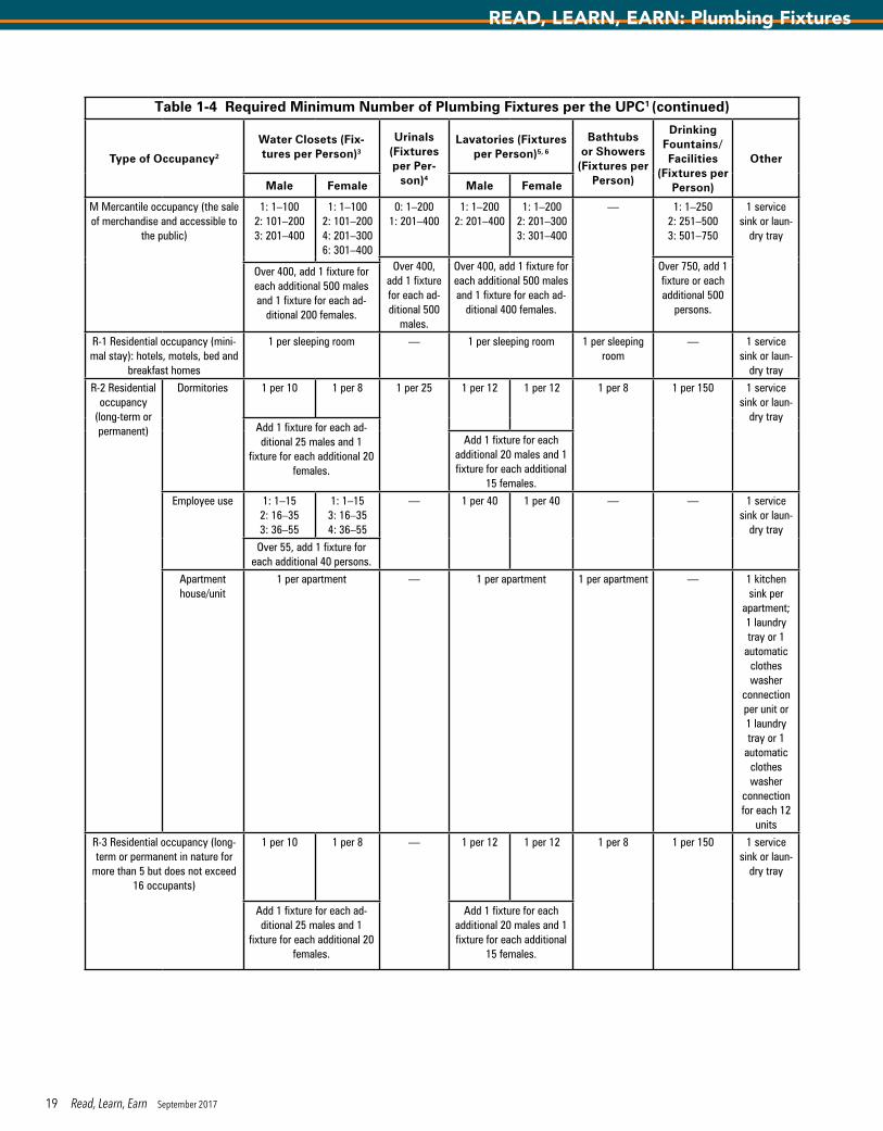
Table 1-4 Required Minimum Number of Plumbing Fixtures per the UPC1 (continued)
Type of Occupancy2
Water Closets (Fix-tures per Person)3
Urinals (Fixtures per Per-
son)4
Lavatories (Fixtures per Person)5, 6
Bathtubs or Showers
(Fixtures per Person)
Drinking Fountains/Facilities
(Fixtures per Person)
Other
Male Female Male Female
M Mercantile occupancy (the sale of merchandise and accessible to
the public)
1: 1–1002: 101–2003: 201–400
1: 1–1002: 101–2004: 201–3006: 301–400
0: 1–2001: 201–400
1: 1–2002: 201–400
1: 1–2002: 201–3003: 301–400
— 1: 1–2502: 251–5003: 501–750
1 service sink or laun-
dry tray
Over 400, add 1 fixture for each ad-ditional 500
males.
Over 400, add 1 fixture for each additional 500 males and 1 fixture for each ad-
ditional 400 females.
Over 750, add 1 fixture or each additional 500
persons.
Over 400, add 1 fixture for each additional 500 males and 1 fixture for each ad-
ditional 200 females.
R-1 Residential occupancy (mini-mal stay): hotels, motels, bed and
breakfast homes
1 per sleeping room — 1 per sleeping room 1 per sleeping room
— 1 service sink or laun-
dry tray
R-2 Residential occupancy
(long-term or permanent)
Dormitories 1 per 10 1 per 8 1 per 25 1 per 12 1 per 12 1 per 8 1 per 150 1 service sink or laun-
dry trayAdd 1 fixture for each ad-ditional 25 males and 1
fixture for each additional 20 females.
Add 1 fixture for each additional 20 males and 1 fixture for each additional
15 females.
Employee use 1: 1–152: 16–353: 36–55
1: 1–153: 16–354: 36–55
— 1 per 40 1 per 40 — — 1 service sink or laun-
dry tray
Over 55, add 1 fixture for each additional 40 persons.
Apartment house/unit
1 per apartment — 1 per apartment 1 per apartment — 1 kitchen sink per
apartment; 1 laundry tray or 1
automatic clothes washer
connection per unit or 1 laundry tray or 1
automatic clothes washer
connection for each 12
units
R-3 Residential occupancy (long-term or permanent in nature for
more than 5 but does not exceed 16 occupants)
1 per 10 1 per 8 — 1 per 12 1 per 12 1 per 8 1 per 150 1 service sink or laun-
dry tray
Add 1 fixture for each ad-ditional 25 males and 1
fixture for each additional 20 females.
Add 1 fixture for each additional 20 males and 1 fixture for each additional
15 females.
19 Read, Learn, Earn September 2017
READ, LEARN, EARN: Plumbing Fixtures

Table 1-4 Required Minimum Number of Plumbing Fixtures per the UPC1 (continued)
Type of Occupancy2
Water Closets (Fix-tures per Person)3 Urinals
(Fixtures per Per-
son)4
Lavatories (Fixtures per Person)5, 6 Bathtubs
or Showers (Fixtures per
Person)
Drinking Fountains/Facilities
(Fixtures per Person)
OtherMale Female Male Female
R-3 Residential occupancy (one- and two-family dwellings)
1 per one- and two-family dwelling
— 1 per one- and two-family dwelling
1 per one- and two-family dwelling
— 1 kitchen sink and 1 automatic
clothes washer
connection per one- and two-family dwelling
R-4 Residential occupancy (resi-dential care or assisted living)
1 per 10 1 per 8 — 1 per 12 1 per 12 1 per 8 1 per 150 1 service sink or laun-
dry trayAdd 1 fixture for each ad-ditional 25 males and 1
fixture for each additional 20 females.
Add 1 fixture for each additional 20 males and 1 fixture for each additional
15 females.
S-1, S-2 Storage occupancy: stor-age of goods, warehouse, aircraft hanger, food products, appliances
1: 1–1002: 101–2003: 201–400
1: 1–1002: 101–2003: 201–400
— 1: 1–2002: 201–4003: 401–750
1: 1–2002: 201–4003: 401–750
— 1: 1–2502: 251–5003: 501–750
1 service sink or laun-
dry tray
Over 750, add 1 fixture for each additional 500
persons.
Over 400, add 1 fixture for each additional 500 males and 1 fixture for each ad-
ditional 150 females.
Over 750, add 1 fixture for each additional 500
persons.
1 The figures shown are based on one fixture being the minimum required for the number of persons indicated or any fraction thereof.2 A restaurant is defined as a business that sells food to be consumed on the premises.a. The number of occupants for a drive-in restaurant shall be considered as equal to the number of parking stalls.b. Handwashing facilities shall be available in the kitchen for employees.3 The total number of required water closets for females shall be not less than the total number of required water closets and urinals for males.4 For each urinal added in excess of the minimum required, one water closet shall be permitted to be deducted. The number of water closets shall not be reduced
to less than two-thirds of the minimum requirement.5 Group lavatories that are 24 lineal inches (630 mm) of wash sink or 18 inches (457 mm) of a circular basin, where provided with water outlets for such space,
shall be considered equivalent to one lavatory.6 Metering or self-closing faucets shall be installed on lavatories intended to serve the transient public.Source: UPC Table 422.1. Reprinted with the permission of the International Association of Plumbing and Mechanical Officials. This copyright material and all
points or statements in using this material have not been reviewed by IAPMO. The opinions expressed herein are not representations of fact from IAPMO.
20 Read, Learn, Earn September 2017
READ, LEARN, EARN: Plumbing Fixtures

1. Plumbing fixtures that are produced from a stainless-steel alloy may have varying finishes and surface sheens due to one key element that is _______.
a. carbonb. chromiumc. manganesed. nickel
2. The plumbing fixtures subject to the ARI 1010 Standard are _______.a. bathtubsb. lavatoriesc. water closetsd. water coolers
3. The water closet rim height designated for juvenile use is _______.a. 10 inchesb. 13 inchesc. 15 inchesd. 17 inches
4. The gravity tank water closets consist of several parts, but the one part that controls the flow of water entering the tank is a(n) _______.
a. anti-siphon ballcockb. floatc. overflowd. refill tube
5. Water closets that are equipped with dual-flush flushometers have the potential of consuming only _______ of the water per flush with use of the liquid waste flush activation option versus the solid waste flush activation option.
a. 25 percentb. 30 percentc. 35 percentd. 70 percent
6. A full-bath macerating toilet system that has a 1¼-inch vent pipe shall have a minimum _______ discharge soil pipe.
a. ¾-inchb. 1¼-inchc. 1½-inchd. 2-inch
7. Although residential kitchen sinks are typically 9 to 10 inches deep, an acceptable accessible sink depth is _______.
a. 5½ inchesb. 6 inchesc. 6½ inchesd. all of the above
8. Pressure-balancing valves for use on individual showers as an anti-scalding protection device cannot display a temperature fluctuation greater than _______ when tested.
a. 1°Fb. 1.5°Fc. 3°Fd. 5°F
9. The flow rate restrictions for a handheld shower spray may not exceed _______.
a. 2.0 gpm at 60 psib. 2.2 gpm at 60 psic. 2.5 gpm at 60 psid. 2.5 gpm at 80 psi
10. The bidet is intended for external cleansing of the perineal area and use for _______.
a. females onlyb. males onlyc. both females and malesd. internal body cleansing as well
11. Even though one may have a thorough understanding of the ISEA Z358.1 Standard, the responsible plumbing engineer should still consult a(n) _______ in determining the optimal water temperature for a given hazard at a facility.
a. local AHJb. medical professionalc. OSHA officiald. owner/facilities manager
12. A gentleman wishes to open a professional investment service business in an available open space large enough to support up to 55 employees. What would be the minimum required fixtures for the women’s restroom that would be compliant with both the IPC and UPC, assuming that about half of the employees are women?
a. 1 water closet and 1 lavatoryb. 2 water closets and 1 lavatoryc. 2 water closets and 2 lavatoriesd. 3 water closets and 2 lavatories
ASPE Read, Learn, Earn Continuing EducationYou may submit your answers to the following questions online at aspe.org/readlearnearn. If you score 90 percent or higher on the test, you will be notified that you have earned 0.1 CEU, which can be applied toward CPD renewal or numerous regulatory-agency CE programs. (Please note that it is your responsibility to determine the acceptance policy of a particular agency.) CEU information will be kept on file at the ASPE office for three years.
Notice for North Carolina Professional Engineers: State regulations for registered PEs in North Carolina now require you to complete ASPE’s online CEU validation form to be eligible for continuing education credits. After successfully completing this quiz, just visit ASPE’s CEU Validation Center at aspe.org/CEUValidationCenter.
Expiration date: Continuing education credit will be given for this examination through September 30, 2018.
CE Questions — “Plumbing Fixtures” (CEU 251)Test written by David Bailey, EIT, CPD, GPD, FASPE