Embed Size (px)
Citation preview
Phoenix Contact Inc. • P.O. Box 4100 • Harrisburg, PA 17111 • Phone: (717) 944-1300 • Fax: (717) 944-1625
1
Installation and Technical Data Brochure 1364B
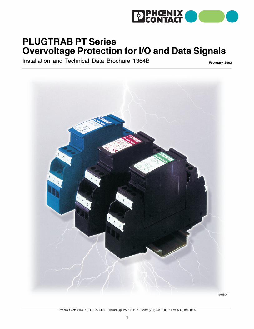
PLUGTRAB PT SeriesOvervoltage Protection for I/O and Data Signals
February 2003

Phoenix Contact Inc. • P.O. Box 4100 • Harrisburg, PA 17111 • Phone: (717) 944-1300 • Fax: (717) 944-1625
2
PLUGTRAB PT Series
Table of Contents
Overvoltage Protection for I/O and Data Signals
Grounding of PLUGTRAB PT Surge Protectors
Analog Signal Protection (Floating Ground Circuits)
Discrete Signal Protection (Ground Referenced Circuits)
120 V ac Discrete Signal Protection
Data Signal Protection (DATA-PLUGTRABs)
Three and Four Wire Sensor Protection
CHECKMASTER Tester
Publications
Phoenix Contact Inc. • P.O. Box 4100 • Harrisburg, PA 17111 • Phone: (717) 944-1300 • Fax: (717) 944-1625
3
5
7
9
13
17
21
27
29
30

About This Guide
The wiring instructions shown in this guide are meantto represent the most common protection applications.Different applications may require alternativeapproaches. Contact Phoenix Contact TechnicalServices to discuss @ 1-800-322-3225.
When protecting data and I/O signals it is important toconsider both ends of the signal line. Surges causedby lightning or other sources can propagate in eitherdirection. Electronics at both ends are thereforesusceptible and require a comprehensive protectionapproach. For clarity the wiring diagrams in this guideshow only protection of the control end. The fielddevices should also be considered.
Phoenix Contact Inc. • P.O. Box 4100 • Harrisburg, PA 17111 • Phone: (717) 944-1300 • Fax: (717) 944-1625
4
Phoenix Contact Inc. • P.O. Box 4100 • Harrisburg, PA 17111 • Phone: (717) 944-1300 • Fax: (717) 944-1625
5
Brochure 1364B
PLUGTRAB PT SeriesOvervoltage Protection for I/Oand Data Signals
February 2003
The Phoenix Contact PLUGTRAB PT series allowsthese previously vulnerable pathways to maintain thereliability originally intended. The PLUGTRAB PTseries offers protection from even the toughest oftransients…those caused by direct or close-bylightning events.
The DIN-rail mount, pluggable, high-density packageprovides up to 10 kA of surge protection per signal ordata line. Protection is mostly achieved through the
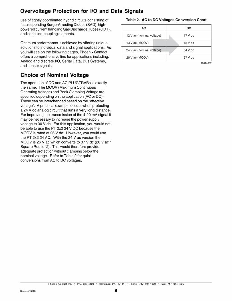
Figure 2. PLUGTRAB PT Dimensions
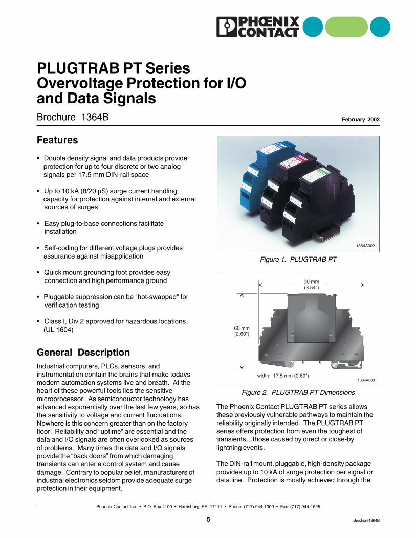
Figure 1. PLUGTRAB PT
Features
• Double density signal and data products provide protection for up to four discrete or two analog signals per 17.5 mm DIN-rail space
• Up to 10 kA (8/20 µS) surge current handling capacity for protection against internal and external sources of surges
• Easy plug-to-base connections facilitate installation
• Self-coding for different voltage plugs provides assurance against misapplication
• Quick mount grounding foot provides easy connection and high performance ground
• Pluggable suppression can be "hot-swapped" for verification testing
• Class I, Div 2 approved for hazardous locations (UL 1604)
General DescriptionIndustrial computers, PLCs, sensors, andinstrumentation contain the brains that make todaysmodern automation systems live and breath. At theheart of these powerful tools lies the sensitivemicroprocessor. As semiconductor technology hasadvanced exponentially over the last few years, so hasthe sensitivity to voltage and current fluctuations.Nowhere is this concern greater than on the factoryfloor. Reliability and “uptime” are essential and thedata and I/O signals are often overlooked as sourcesof problems. Many times the data and I/O signalsprovide the “back doors” from which damagingtransients can enter a control system and causedamage. Contrary to popular belief, manufacturers ofindustrial electronics seldom provide adequate surgeprotection in their equipment.
Brochure1364B
6Brochure 1364B
Overvoltage Protection for I/O and Data Signals
Phoenix Contact Inc. • P.O. Box 4100 • Harrisburg, PA 17111 • Phone: (717) 944-1300 • Fax: (717) 944-1625
use of tightly coordinated hybrid circuits consisting offast responding Surge-Arresting Diodes (SAD), high-powered current handling Gas Discharge Tubes (GDT),and series de-coupling elements.
Optimum performance is achieved by offering uniquesolutions to individual data and signal applications. Asyou will see on the following pages, Phoenix Contactoffers a comprehensive line for applications including:Analog and discrete I/O, Serial Data, Bus Systems,and sensor signals.
Choice of Nominal VoltageThe operation of DC and AC PLUGTRABs is exactlythe same. The MCOV (Maximum ContinuousOperating Voltage) and Peak Clamping Voltage arespecified depending on the application (AC or DC).These can be interchanged based on the “effectivevoltage”. A practical example occurs when protectinga 24 V dc analog circuit that runs a very long distance.For improving the transmission of the 4-20 mA signal itmay be necessary to increase the power supplyvoltage to 30 V dc. For this application, you would notbe able to use the PT 2x2 24 V DC because theMCOV is rated at 26 V dc. However, you could usethe PT 2x2 24 AC. With the 24 V ac version theMCOV is 26 V ac which converts to 37 V dc (26 V ac *Square Root of 2). This would therefore provideadequate protection without clamping below thenominal voltage. Refer to Table 2 for quickconversions from AC to DC voltages.
Table 2. AC to DC Voltages Conversion Chart
Phoenix Contact Inc. • P.O. Box 4100 • Harrisburg, PA 17111 • Phone: (717) 944-1300 • Fax: (717) 944-1625
7
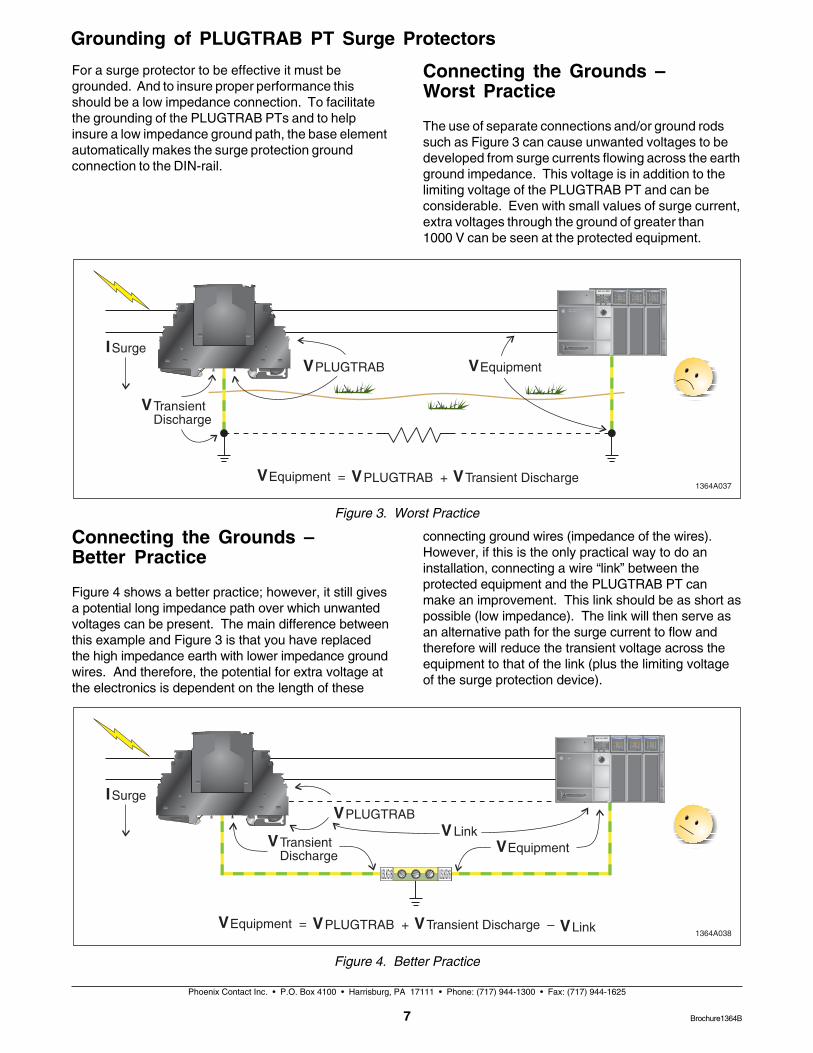
Connecting the Grounds –Better Practice
Figure 4 shows a better practice; however, it still givesa potential long impedance path over which unwantedvoltages can be present. The main difference betweenthis example and Figure 3 is that you have replacedthe high impedance earth with lower impedance groundwires. And therefore, the potential for extra voltage atthe electronics is dependent on the length of these
Figure 3. Worst Practice
Figure 4. Better Practice
Brochure1364B
Grounding of PLUGTRAB PT Surge Protectors
For a surge protector to be effective it must begrounded. And to insure proper performance thisshould be a low impedance connection. To facilitatethe grounding of the PLUGTRAB PTs and to helpinsure a low impedance ground path, the base elementautomatically makes the surge protection groundconnection to the DIN-rail.
connecting ground wires (impedance of the wires).However, if this is the only practical way to do aninstallation, connecting a wire “link” between theprotected equipment and the PLUGTRAB PT canmake an improvement. This link should be as short aspossible (low impedance). The link will then serve asan alternative path for the surge current to flow andtherefore will reduce the transient voltage across theequipment to that of the link (plus the limiting voltageof the surge protection device).
Connecting the Grounds –Worst Practice
The use of separate connections and/or ground rodssuch as Figure 3 can cause unwanted voltages to bedeveloped from surge currents flowing across the earthground impedance. This voltage is in addition to thelimiting voltage of the PLUGTRAB PT and can beconsiderable. Even with small values of surge current,extra voltages through the ground of greater than1000 V can be seen at the protected equipment.
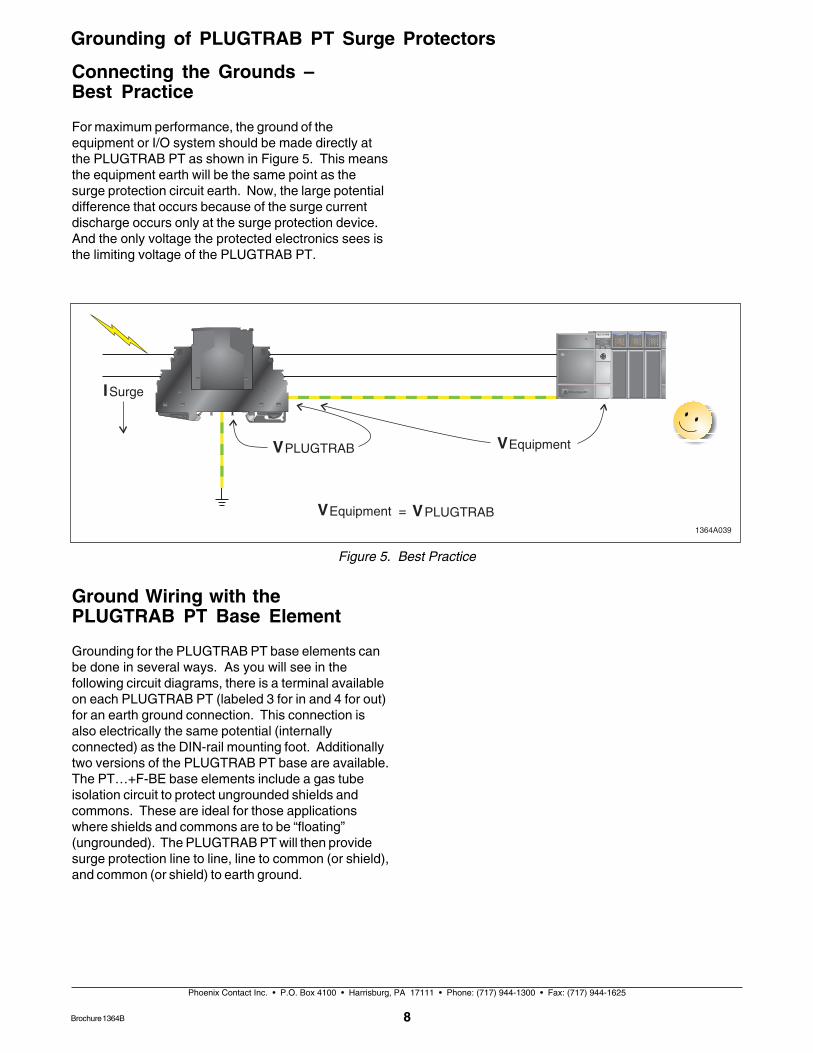
Figure 5. Best Practice
Phoenix Contact Inc. • P.O. Box 4100 • Harrisburg, PA 17111 • Phone: (717) 944-1300 • Fax: (717) 944-1625
8
Connecting the Grounds –Best Practice
For maximum performance, the ground of theequipment or I/O system should be made directly atthe PLUGTRAB PT as shown in Figure 5. This meansthe equipment earth will be the same point as thesurge protection circuit earth. Now, the large potentialdifference that occurs because of the surge currentdischarge occurs only at the surge protection device.And the only voltage the protected electronics sees isthe limiting voltage of the PLUGTRAB PT.
Ground Wiring with thePLUGTRAB PT Base Element
Grounding for the PLUGTRAB PT base elements canbe done in several ways. As you will see in thefollowing circuit diagrams, there is a terminal availableon each PLUGTRAB PT (labeled 3 for in and 4 for out)for an earth ground connection. This connection isalso electrically the same potential (internallyconnected) as the DIN-rail mounting foot. Additionallytwo versions of the PLUGTRAB PT base are available.The PT…+F-BE base elements include a gas tubeisolation circuit to protect ungrounded shields andcommons. These are ideal for those applicationswhere shields and commons are to be “floating”(ungrounded). The PLUGTRAB PT will then providesurge protection line to line, line to common (or shield),and common (or shield) to earth ground.
Grounding of PLUGTRAB PT Surge Protectors
Brochure 1364B
Note: indicates potential earthalso called earth ground. Thisis the same potential as the
DIN-rail mounting foot.1364A029
Phoenix Contact Inc. • P.O. Box 4100 • Harrisburg, PA 17111 • Phone: (717) 944-1300 • Fax: (717) 944-1625
9
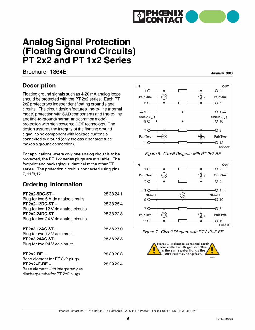
Figure 6. Circuit Diagram with PT 2x2-BE
Brochure 1364B
Analog Signal Protection(Floating Ground Circuits)PT 2x2 and PT 1x2 Series
January 2003
Figure 7. Circuit Diagram with PT 2x2+F-BE
PT 2x2-5DC-ST –Plug for two 5 V dc analog circuitsPT 2x2-12DC-ST –Plug for two 12 V dc analog circuitsPT 2x2-24DC-ST –Plug for two 24 V dc analog circuits
PT 2x2-12AC-ST –Plug for two 12 V ac circuitsPT 2x2-24AC-ST –Plug for two 24 V ac circuits
PT 2x2-BE –Base element for PT 2x2 plugsPT 2x2+F-BE –Base element with integrated gasdischarge tube for PT 2x2 plugs
28 38 24 1
28 38 25 4
28 38 22 8
28 38 27 0
28 38 28 3
28 39 20 8
28 39 22 4
DescriptionFloating ground signals such as 4-20 mA analog loopsshould be protected with the PT 2x2 series. Each PT2x2 protects two independent floating ground signalcircuits. The circuit design features line-to-line (normalmode) protection with SAD components and line-to-lineand line-to-ground (normal and common mode)protection with high powered GDT technology. Thedesign assures the integrity of the floating groundsignal as no component with leakage current isconnected to ground (only the gas discharge tubemakes a ground connection).
For applications where only one analog circuit is to beprotected, the PT 1x2 series plugs are available. Thefootprint and packaging is identical to the other PTseries. The protection circuit is connected using pins7, 11/8,12.
Ordering Information
Brochure1364B
10
Analog Signal Protection (Floating Ground Circuits)PT 2x2 and PT 1x2 Series
Phoenix Contact Inc. • P.O. Box 4100 • Harrisburg, PA 17111 • Phone: (717) 944-1300 • Fax: (717) 944-1625
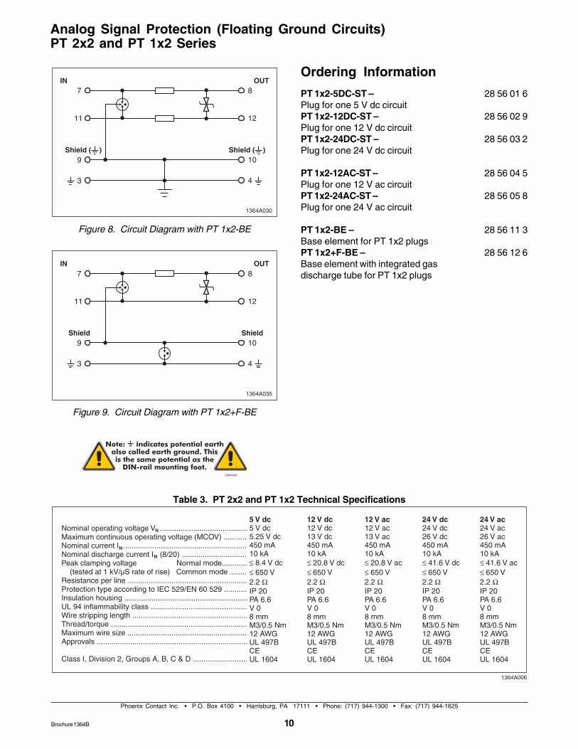
Table 3. PT 2x2 and PT 1x2 Technical Specifications
Note: indicates potential earthalso called earth ground. Thisis the same potential as the
DIN-rail mounting foot.1364A029
Figure 8. Circuit Diagram with PT 1x2-BE
PT 1x2-5DC-ST –Plug for one 5 V dc circuitPT 1x2-12DC-ST –Plug for one 12 V dc circuitPT 1x2-24DC-ST –Plug for one 24 V dc circuit
PT 1x2-12AC-ST –Plug for one 12 V ac circuitPT 1x2-24AC-ST –Plug for one 24 V ac circuit
PT 1x2-BE –Base element for PT 1x2 plugsPT 1x2+F-BE –Base element with integrated gasdischarge tube for PT 1x2 plugs
28 56 01 6
28 56 02 9
28 56 03 2
28 56 04 5
28 56 05 8
28 56 11 3
28 56 12 6
Ordering Information
Figure 9. Circuit Diagram with PT 1x2+F-BE
Brochure 1364B
Phoenix Contact Inc. • P.O. Box 4100 • Harrisburg, PA 17111 • Phone: (717) 944-1300 • Fax: (717) 944-1625
11
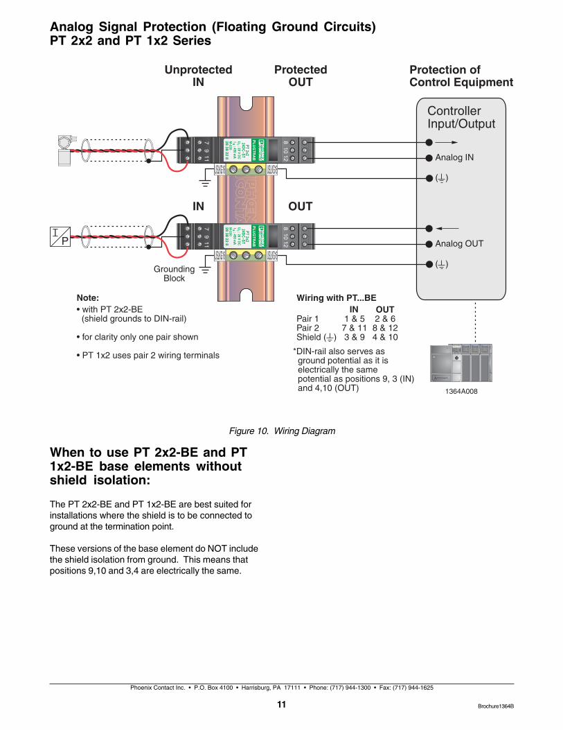
When to use PT 2x2-BE and PT1x2-BE base elements withoutshield isolation:
The PT 2x2-BE and PT 1x2-BE are best suited forinstallations where the shield is to be connected toground at the termination point.
These versions of the base element do NOT includethe shield isolation from ground. This means thatpositions 9,10 and 3,4 are electrically the same.
Figure 10. Wiring Diagram
Analog Signal Protection (Floating Ground Circuits)PT 2x2 and PT 1x2 Series
Brochure1364B
12
Phoenix Contact Inc. • P.O. Box 4100 • Harrisburg, PA 17111 • Phone: (717) 944-1300 • Fax: (717) 944-1625
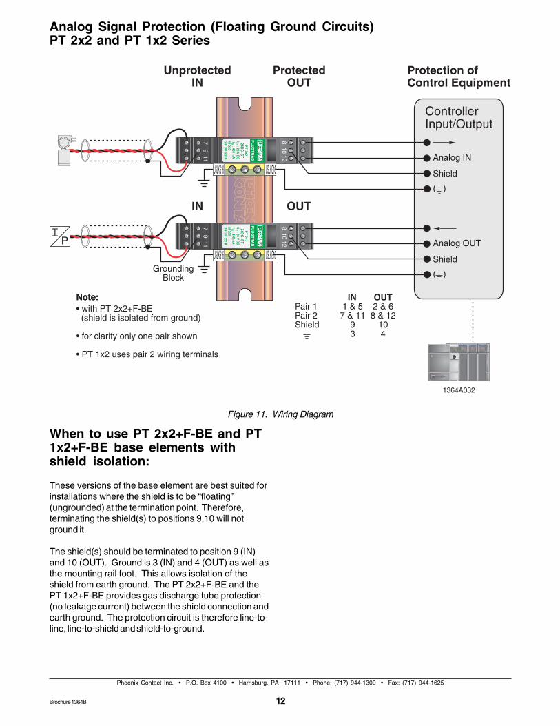
Figure 11. Wiring Diagram
Analog Signal Protection (Floating Ground Circuits)PT 2x2 and PT 1x2 Series
When to use PT 2x2+F-BE and PT1x2+F-BE base elements withshield isolation:
These versions of the base element are best suited forinstallations where the shield is to be “floating”(ungrounded) at the termination point. Therefore,terminating the shield(s) to positions 9,10 will notground it.
The shield(s) should be terminated to position 9 (IN)and 10 (OUT). Ground is 3 (IN) and 4 (OUT) as well asthe mounting rail foot. This allows isolation of theshield from earth ground. The PT 2x2+F-BE and thePT 1x2+F-BE provides gas discharge tube protection(no leakage current) between the shield connection andearth ground. The protection circuit is therefore line-to-line, line-to-shield and shield-to-ground.
Brochure 1364B
Note: indicates potential earthalso called earth ground. Thisis the same potential as the
DIN-rail mounting foot.1364A029
Phoenix Contact Inc. • P.O. Box 4100 • Harrisburg, PA 17111 • Phone: (717) 944-1300 • Fax: (717) 944-1625
13
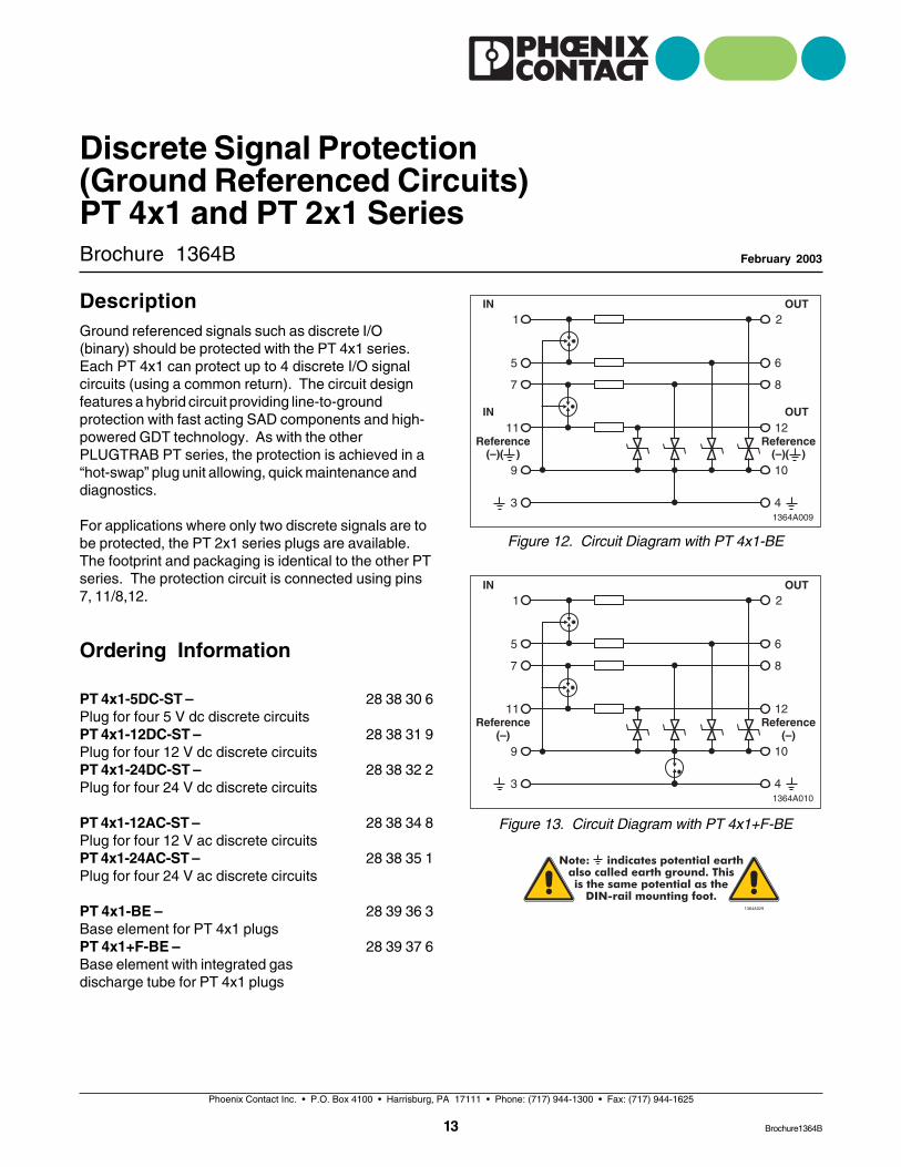
Figure 12. Circuit Diagram with PT 4x1-BE
Brochure 1364B
Discrete Signal Protection(Ground Referenced Circuits)PT 4x1 and PT 2x1 Series
February 2003
Figure 13. Circuit Diagram with PT 4x1+F-BE
PT 4x1-5DC-ST –Plug for four 5 V dc discrete circuitsPT 4x1-12DC-ST –Plug for four 12 V dc discrete circuitsPT 4x1-24DC-ST –Plug for four 24 V dc discrete circuits
PT 4x1-12AC-ST –Plug for four 12 V ac discrete circuitsPT 4x1-24AC-ST –Plug for four 24 V ac discrete circuits
PT 4x1-BE –Base element for PT 4x1 plugsPT 4x1+F-BE –Base element with integrated gasdischarge tube for PT 4x1 plugs
28 38 30 6
28 38 31 9
28 38 32 2
28 38 34 8
28 38 35 1
28 39 36 3
28 39 37 6
DescriptionGround referenced signals such as discrete I/O(binary) should be protected with the PT 4x1 series.Each PT 4x1 can protect up to 4 discrete I/O signalcircuits (using a common return). The circuit designfeatures a hybrid circuit providing line-to-groundprotection with fast acting SAD components and high-powered GDT technology. As with the otherPLUGTRAB PT series, the protection is achieved in a“hot-swap” plug unit allowing, quick maintenance anddiagnostics.
For applications where only two discrete signals are tobe protected, the PT 2x1 series plugs are available.The footprint and packaging is identical to the other PTseries. The protection circuit is connected using pins7, 11/8,12.
Ordering Information
Brochure1364B
14
Phoenix Contact Inc. • P.O. Box 4100 • Harrisburg, PA 17111 • Phone: (717) 944-1300 • Fax: (717) 944-1625
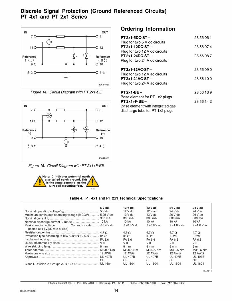
Table 4. PT 4x1 and PT 2x1 Technical Specifications
Discrete Signal Protection (Ground Referenced Circuits)PT 4x1 and PT 2x1 Series
Note: indicates potential earthalso called earth ground. Thisis the same potential as the
DIN-rail mounting foot.1364A029
Figure 14. Circuit Diagram with PT 2x1-BE
PT 2x1-5DC-ST –Plug for two 5 V dc circuitsPT 2x1-12DC-ST –Plug for two 12 V dc circuitsPT 2x1-24DC-ST –Plug for two 24 V dc circuits
PT 2x1-12AC-ST –Plug for two 12 V ac circuitsPT 2x1-24AC-ST –Plug for two 24 V ac circuits
PT 2x1-BE –Base element for PT 1x2 plugsPT 2x1+F-BE –Base element with integrated gasdischarge tube for PT 1x2 plugs
28 56 06 1
28 56 07 4
28 56 08 7
28 56 09 0
28 56 10 0
28 56 13 9
28 56 14 2
Ordering Information
Figure 15. Circuit Diagram with PT 2x1+F-BE
Brochure 1364B
Phoenix Contact Inc. • P.O. Box 4100 • Harrisburg, PA 17111 • Phone: (717) 944-1300 • Fax: (717) 944-1625
15
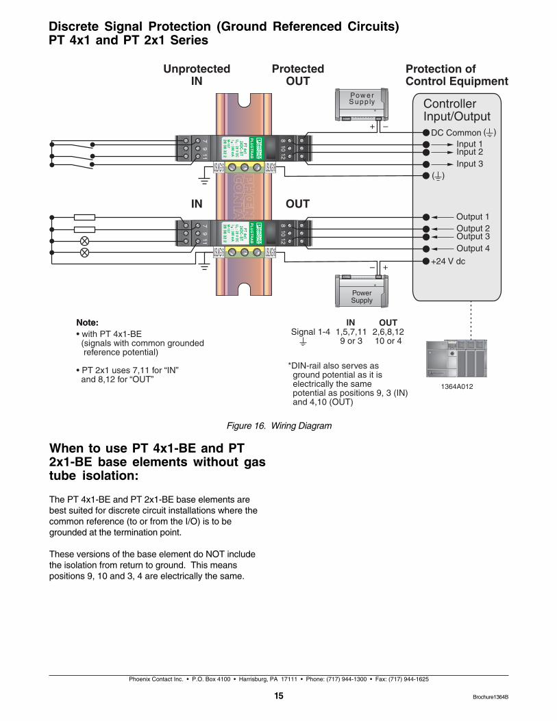
Figure 16. Wiring Diagram
Discrete Signal Protection (Ground Referenced Circuits)PT 4x1 and PT 2x1 Series
When to use PT 4x1-BE and PT2x1-BE base elements without gastube isolation:
The PT 4x1-BE and PT 2x1-BE base elements arebest suited for discrete circuit installations where thecommon reference (to or from the I/O) is to begrounded at the termination point.
These versions of the base element do NOT includethe isolation from return to ground. This meanspositions 9, 10 and 3, 4 are electrically the same.
Brochure1364B
16
Phoenix Contact Inc. • P.O. Box 4100 • Harrisburg, PA 17111 • Phone: (717) 944-1300 • Fax: (717) 944-1625
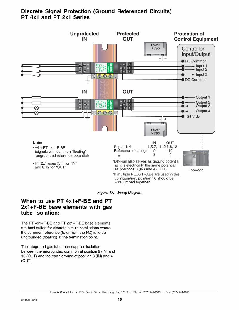
Figure 17. Wiring Diagram
Discrete Signal Protection (Ground Referenced Circuits)PT 4x1 and PT 2x1 Series
When to use PT 4x1+F-BE and PT2x1+F-BE base elements with gastube isolation:
The PT 4x1+F-BE and PT 2x1+F-BE base elementsare best suited for discrete circuit installations wherethe common reference (to or from the I/O) is to beungrounded (floating) at the termination point.
The integrated gas tube then supplies isolationbetween the ungrounded common at position 9 (IN) and10 (OUT) and the earth ground at position 3 (IN) and 4(OUT).
Brochure 1364B
Phoenix Contact Inc. • P.O. Box 4100 • Harrisburg, PA 17111 • Phone: (717) 944-1300 • Fax: (717) 944-1625
17
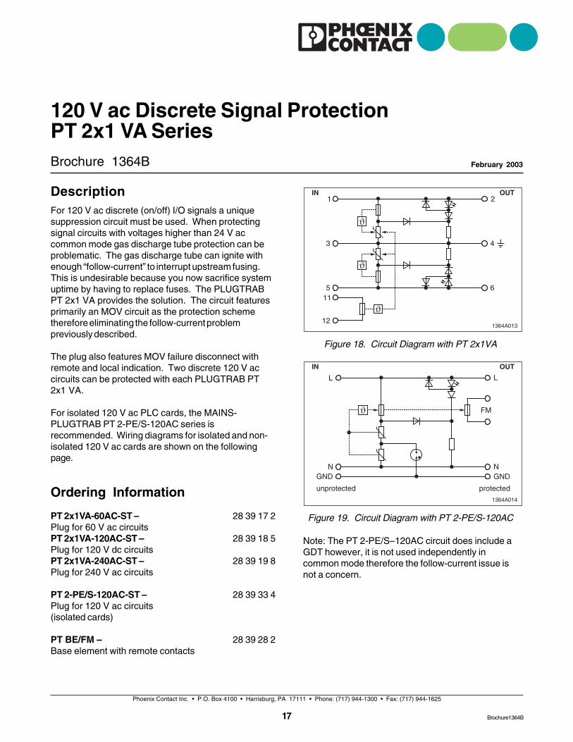
Figure 18. Circuit Diagram with PT 2x1VA
Brochure 1364B
120 V ac Discrete Signal ProtectionPT 2x1 VA Series
February 2003
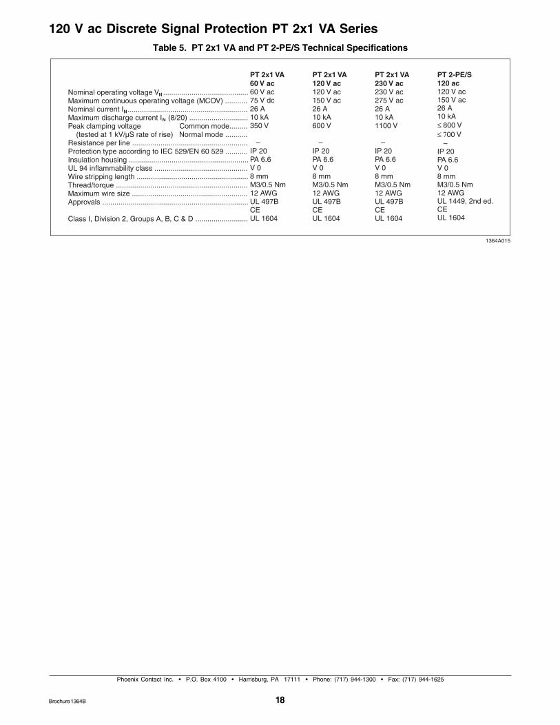
Figure 19. Circuit Diagram with PT 2-PE/S-120ACPT 2x1VA-60AC-ST –Plug for 60 V ac circuitsPT 2x1VA-120AC-ST –Plug for 120 V dc circuitsPT 2x1VA-240AC-ST –Plug for 240 V ac circuits
PT 2-PE/S-120AC-ST –Plug for 120 V ac circuits(isolated cards)
PT BE/FM –Base element with remote contacts
28 39 17 2
28 39 18 5
28 39 19 8
28 39 33 4
28 39 28 2
DescriptionFor 120 V ac discrete (on/off) I/O signals a uniquesuppression circuit must be used. When protectingsignal circuits with voltages higher than 24 V accommon mode gas discharge tube protection can beproblematic. The gas discharge tube can ignite withenough “follow-current” to interrupt upstream fusing.This is undesirable because you now sacrifice systemuptime by having to replace fuses. The PLUGTRABPT 2x1 VA provides the solution. The circuit featuresprimarily an MOV circuit as the protection schemetherefore eliminating the follow-current problempreviously described.
The plug also features MOV failure disconnect withremote and local indication. Two discrete 120 V accircuits can be protected with each PLUGTRAB PT2x1 VA.
For isolated 120 V ac PLC cards, the MAINS-PLUGTRAB PT 2-PE/S-120AC series isrecommended. Wiring diagrams for isolated and non-isolated 120 V ac cards are shown on the followingpage.
Ordering Information1364A014
NN
L L
FM
GNDGND
protectedunprotected
OUTIN
Note: The PT 2-PE/S–120AC circuit does include aGDT however, it is not used independently incommon mode therefore the follow-current issue isnot a concern.
Brochure1364B
18
Phoenix Contact Inc. • P.O. Box 4100 • Harrisburg, PA 17111 • Phone: (717) 944-1300 • Fax: (717) 944-1625
120 V ac Discrete Signal Protection PT 2x1 VA SeriesTable 5. PT 2x1 VA and PT 2-PE/S Technical Specifications
Brochure 1364B
Phoenix Contact Inc. • P.O. Box 4100 • Harrisburg, PA 17111 • Phone: (717) 944-1300 • Fax: (717) 944-1625
19
120 V ac Discrete Signal Protection PT 2x1 VA Series
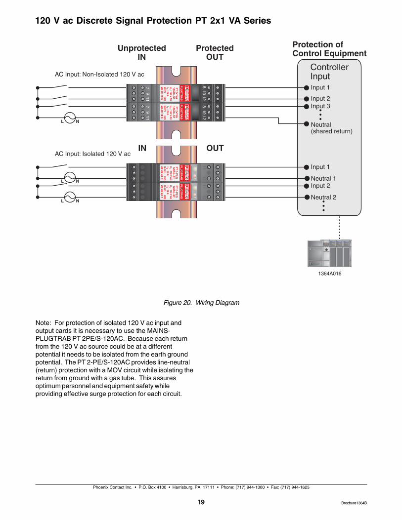
Note: For protection of isolated 120 V ac input andoutput cards it is necessary to use the MAINS-PLUGTRAB PT 2PE/S-120AC. Because each returnfrom the 120 V ac source could be at a differentpotential it needs to be isolated from the earth groundpotential. The PT 2-PE/S-120AC provides line-neutral(return) protection with a MOV circuit while isolating thereturn from ground with a gas tube. This assuresoptimum personnel and equipment safety whileproviding effective surge protection for each circuit.
Figure 20. Wiring Diagram
Brochure1364B
20
Phoenix Contact Inc. • P.O. Box 4100 • Harrisburg, PA 17111 • Phone: (717) 944-1300 • Fax: (717) 944-1625
120 V ac Discrete Signal Protection PT 2x1 VA Series
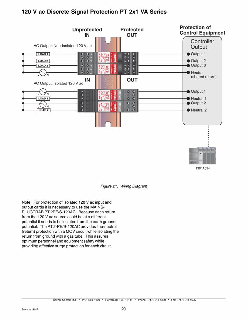
Figure 21. Wiring Diagram
Note: For protection of isolated 120 V ac input andoutput cards it is necessary to use the MAINS-PLUGTRAB PT 2PE/S-120AC. Because each returnfrom the 120 V ac source could be at a differentpotential it needs to be isolated from the earth groundpotential. The PT 2-PE/S-120AC provides line-neutral(return) protection with a MOV circuit while isolating thereturn from ground with a gas tube. This assuresoptimum personnel and equipment safety whileproviding effective surge protection for each circuit.
Brochure 1364B
Note: indicates potential earthalso called earth ground. Thisis the same potential as the
DIN-rail mounting foot.1364A029
Phoenix Contact Inc. • P.O. Box 4100 • Harrisburg, PA 17111 • Phone: (717) 944-1300 • Fax: (717) 944-1625
21
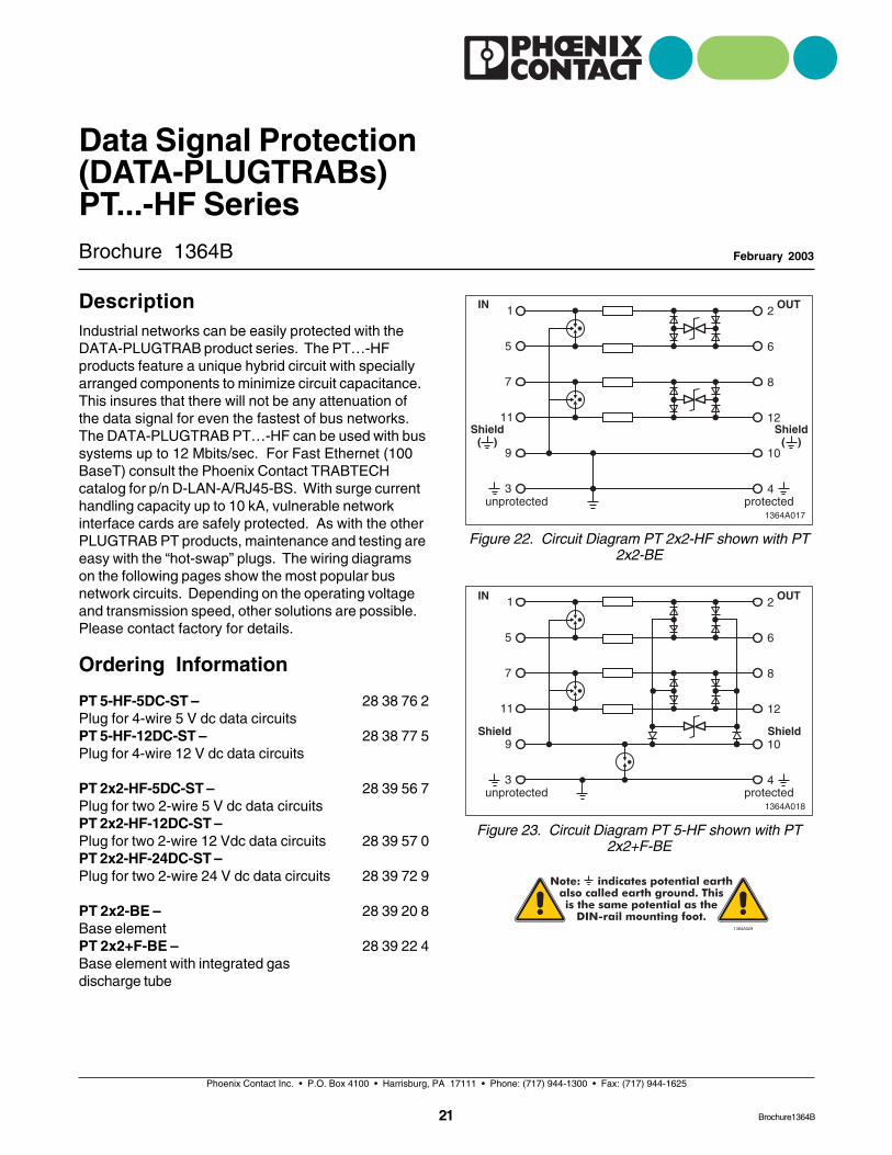
Figure 22. Circuit Diagram PT 2x2-HF shown with PT2x2-BE
Brochure 1364B
Data Signal Protection(DATA-PLUGTRABs)PT...-HF Series
February 2003
Figure 23. Circuit Diagram PT 5-HF shown with PT2x2+F-BE
PT 5-HF-5DC-ST –Plug for 4-wire 5 V dc data circuitsPT 5-HF-12DC-ST –Plug for 4-wire 12 V dc data circuits
PT 2x2-HF-5DC-ST –Plug for two 2-wire 5 V dc data circuitsPT 2x2-HF-12DC-ST –Plug for two 2-wire 12 Vdc data circuitsPT 2x2-HF-24DC-ST –Plug for two 2-wire 24 V dc data circuits
PT 2x2-BE –Base elementPT 2x2+F-BE –Base element with integrated gasdischarge tube
28 38 76 2
28 38 77 5
28 39 56 7
28 39 57 0
28 39 72 9
28 39 20 8
28 39 22 4
DescriptionIndustrial networks can be easily protected with theDATA-PLUGTRAB product series. The PT…-HFproducts feature a unique hybrid circuit with speciallyarranged components to minimize circuit capacitance.This insures that there will not be any attenuation ofthe data signal for even the fastest of bus networks.The DATA-PLUGTRAB PT…-HF can be used with bussystems up to 12 Mbits/sec. For Fast Ethernet (100BaseT) consult the Phoenix Contact TRABTECHcatalog for p/n D-LAN-A/RJ45-BS. With surge currenthandling capacity up to 10 kA, vulnerable networkinterface cards are safely protected. As with the otherPLUGTRAB PT products, maintenance and testing areeasy with the “hot-swap” plugs. The wiring diagramson the following pages show the most popular busnetwork circuits. Depending on the operating voltageand transmission speed, other solutions are possible.Please contact factory for details.
Ordering Information
Brochure1364B
22
Phoenix Contact Inc. • P.O. Box 4100 • Harrisburg, PA 17111 • Phone: (717) 944-1300 • Fax: (717) 944-1625
Data Signal Protection (DATA-PLUGTRABs) PT...-HF Series
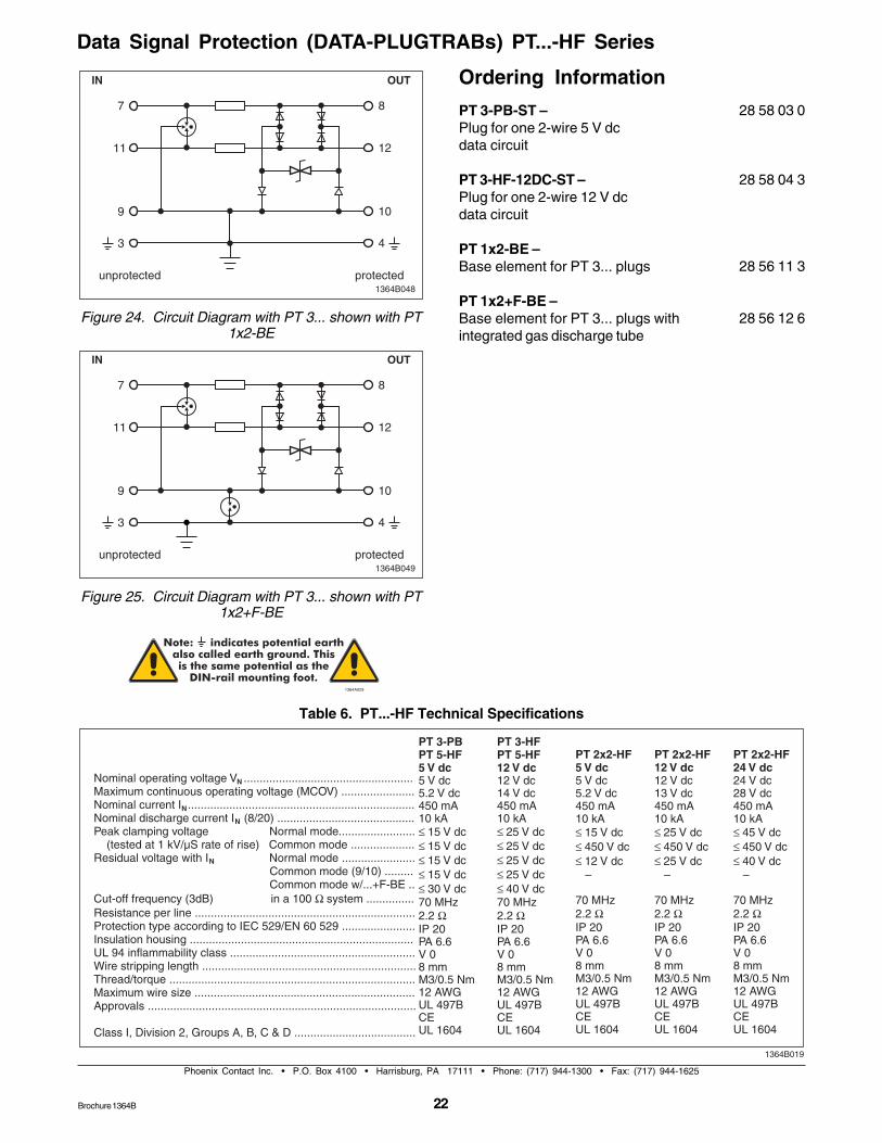
Table 6. PT...-HF Technical Specifications
Brochure 1364B
Figure 24. Circuit Diagram with PT 3... shown with PT1x2-BE
PT 3-PB-ST –Plug for one 2-wire 5 V dcdata circuit
PT 3-HF-12DC-ST –Plug for one 2-wire 12 V dcdata circuit
PT 1x2-BE –Base element for PT 3... plugs
PT 1x2+F-BE –Base element for PT 3... plugs withintegrated gas discharge tube
28 58 03 0
28 58 04 3
28 56 11 3
28 56 12 6
Ordering Information
Figure 25. Circuit Diagram with PT 3... shown with PT1x2+F-BE
Note: indicates potential earthalso called earth ground. Thisis the same potential as the
DIN-rail mounting foot.1364A029
Data Signal Protection (DATA-PLUGTRABs) PT...-HF Series
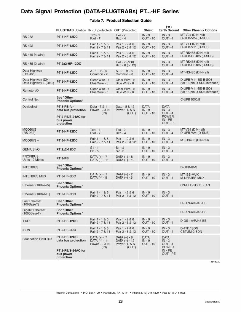
Table 7. Product Selection Guide
Phoenix Contact Inc. • P.O. Box 4100 • Harrisburg, PA 17111 • Phone: (717) 944-1300 • Fax: (717) 944-1625
23 Brochure1364B
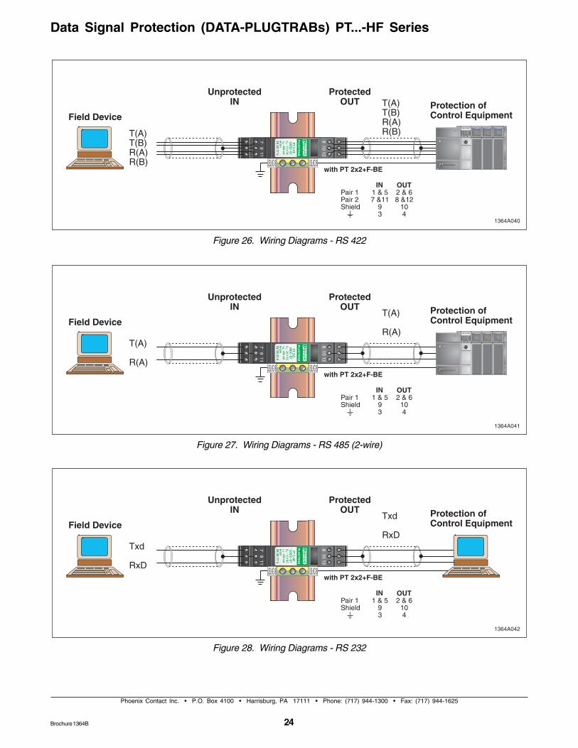
Figure 26. Wiring Diagrams - RS 422
24
Phoenix Contact Inc. • P.O. Box 4100 • Harrisburg, PA 17111 • Phone: (717) 944-1300 • Fax: (717) 944-1625
Data Signal Protection (DATA-PLUGTRABs) PT...-HF Series
Figure 27. Wiring Diagrams - RS 485 (2-wire)
Figure 28. Wiring Diagrams - RS 232
Brochure 1364B
25
Phoenix Contact Inc. • P.O. Box 4100 • Harrisburg, PA 17111 • Phone: (717) 944-1300 • Fax: (717) 944-1625
Data Signal Protection (DATA-PLUGTRABs) PT...-HF Series
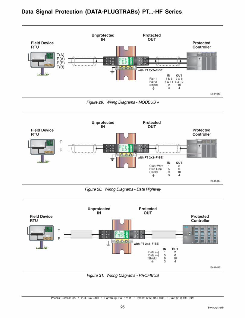
Figure 29. Wiring Diagrams - MODBUS +
Figure 30. Wiring Diagrams - Data Highway
Figure 31. Wiring Diagrams - PROFIBUS
Brochure1364B

26
Phoenix Contact Inc. • P.O. Box 4100 • Harrisburg, PA 17111 • Phone: (717) 944-1300 • Fax: (717) 944-1625
Data Signal Protection (DATA-PLUGTRABs) PT...-HF Series
Brochure 1364B
Phoenix Contact Inc. • P.O. Box 4100 • Harrisburg, PA 17111 • Phone: (717) 944-1300 • Fax: (717) 944-1625
27
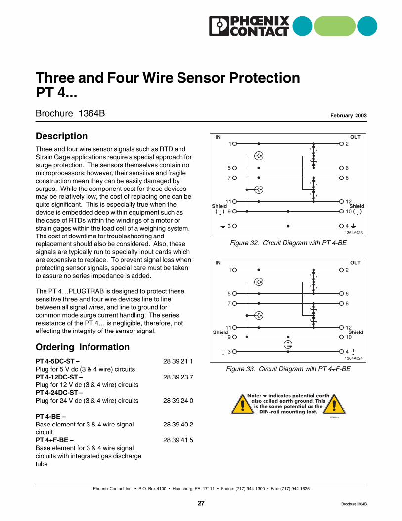
Figure 32. Circuit Diagram with PT 4-BE
Brochure 1364B
Three and Four Wire Sensor ProtectionPT 4...
February 2003
Figure 33. Circuit Diagram with PT 4+F-BEPT 4-5DC-ST –Plug for 5 V dc (3 & 4 wire) circuitsPT 4-12DC-ST –Plug for 12 V dc (3 & 4 wire) circuitsPT 4-24DC-ST –Plug for 24 V dc (3 & 4 wire) circuits
PT 4-BE –Base element for 3 & 4 wire signalcircuitPT 4+F-BE –Base element for 3 & 4 wire signalcircuits with integrated gas dischargetube
28 39 21 1
28 39 23 7
28 39 24 0
28 39 40 2
28 39 41 5
Note: indicates potential earthalso called earth ground. Thisis the same potential as the
DIN-rail mounting foot.1364A029
DescriptionThree and four wire sensor signals such as RTD andStrain Gage applications require a special approach forsurge protection. The sensors themselves contain nomicroprocessors; however, their sensitive and fragileconstruction mean they can be easily damaged bysurges. While the component cost for these devicesmay be relatively low, the cost of replacing one can bequite significant. This is especially true when thedevice is embedded deep within equipment such asthe case of RTDs within the windings of a motor orstrain gages within the load cell of a weighing system.The cost of downtime for troubleshooting andreplacement should also be considered. Also, thesesignals are typically run to specialty input cards whichare expensive to replace. To prevent signal loss whenprotecting sensor signals, special care must be takento assure no series impedance is added.
The PT 4…PLUGTRAB is designed to protect thesesensitive three and four wire devices line to linebetween all signal wires, and line to ground forcommon mode surge current handling. The seriesresistance of the PT 4… is negligible, therefore, noteffecting the integrity of the sensor signal.
Ordering Information
Brochure1364B
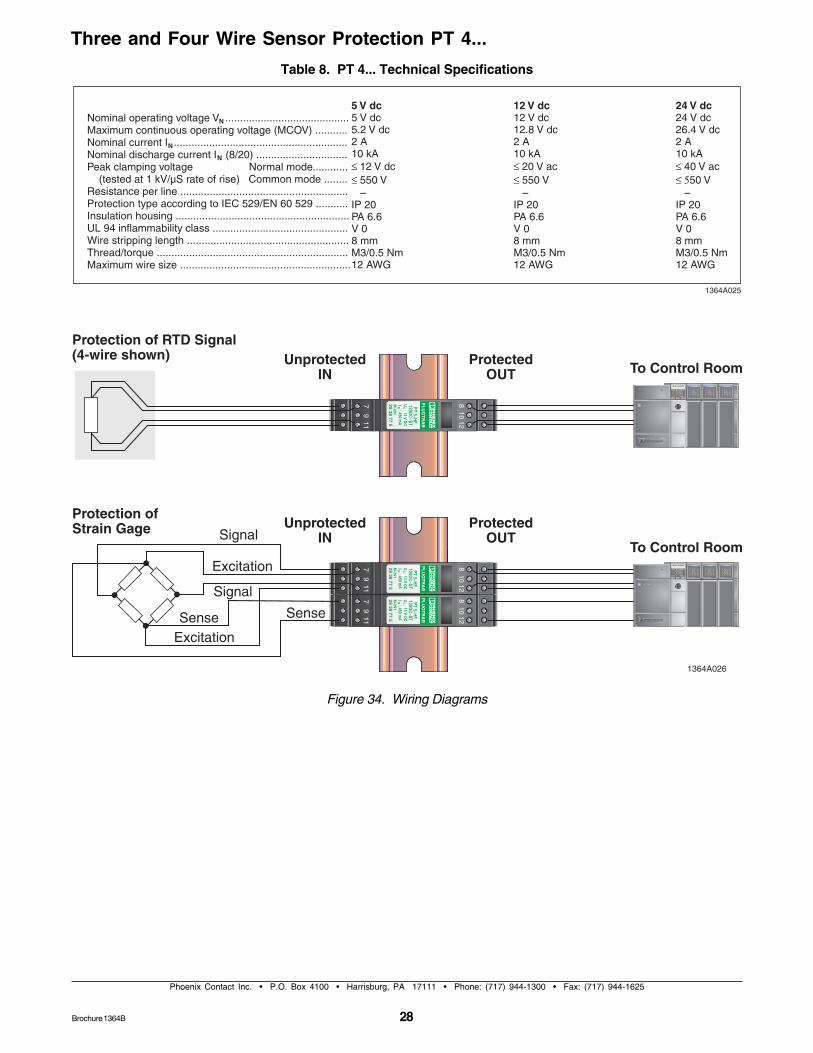
Figure 34. Wiring Diagrams
28
Phoenix Contact Inc. • P.O. Box 4100 • Harrisburg, PA 17111 • Phone: (717) 944-1300 • Fax: (717) 944-1625
Three and Four Wire Sensor Protection PT 4...
Table 8. PT 4... Technical Specifications
Brochure 1364B
29
Phoenix Contact Inc. • P.O. Box 4100 • Harrisburg, PA 17111 • Phone: (717) 944-1300 • Fax: (717) 944-1625
Brochure1364B
Brochure 1364B
CHECKMASTERFebruary 2003
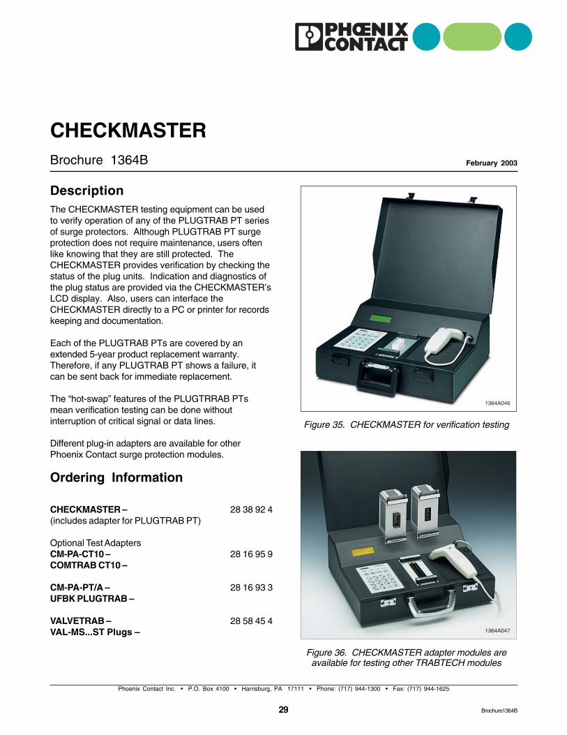
DescriptionThe CHECKMASTER testing equipment can be usedto verify operation of any of the PLUGTRAB PT seriesof surge protectors. Although PLUGTRAB PT surgeprotection does not require maintenance, users oftenlike knowing that they are still protected. TheCHECKMASTER provides verification by checking thestatus of the plug units. Indication and diagnostics ofthe plug status are provided via the CHECKMASTER’sLCD display. Also, users can interface theCHECKMASTER directly to a PC or printer for recordskeeping and documentation.
Each of the PLUGTRAB PTs are covered by anextended 5-year product replacement warranty.Therefore, if any PLUGTRAB PT shows a failure, itcan be sent back for immediate replacement.
The “hot-swap” features of the PLUGTRRAB PTsmean verification testing can be done withoutinterruption of critical signal or data lines.
Different plug-in adapters are available for otherPhoenix Contact surge protection modules.
Ordering Information
CHECKMASTER –(includes adapter for PLUGTRAB PT)
Optional Test AdaptersCM-PA-CT10 –COMTRAB CT10 –
CM-PA-PT/A –UFBK PLUGTRAB –
VALVETRAB –VAL-MS...ST Plugs –
28 38 92 4
28 16 95 9
28 16 93 3
28 58 45 4
Figure 35. CHECKMASTER for verification testing
Figure 36. CHECKMASTER adapter modules areavailable for testing other TRABTECH modules
30
Phoenix Contact Inc. • P.O. Box 4100 • Harrisburg, PA 17111 • Phone: (717) 944-1300 • Fax: (717) 944-1625
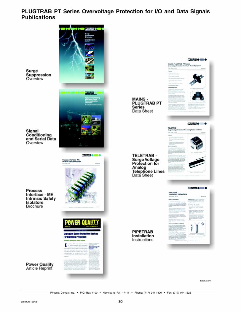
PLUGTRAB PT Series Overvoltage Protection for I/O and Data SignalsPublications
Brochure 1364B

31
Phoenix Contact Inc. • P.O. Box 4100 • Harrisburg, PA 17111 • Phone: (717) 944-1300 • Fax: (717) 944-1625
Brochure1364B
32Brochure1364B
Phoenix Contact Ltd.235 Watline AvenueMississauga, Ontario L4Z 1P3Phone: (905) 890-2820Fax: (905) 890-0180
Headquarters, CanadaHeadquarters, U.S.
The information given herein is based on data believed to be reliable, but Phoenix
Contact Inc. makes no warranties expressed or implied as to the accuracy and
assumes no liability arising out of its use by others. This publication is not to
be taken as license to operate under, or recommendation to infringe, any patent.
Phoenix Contact Inc.P.O. Box 4100Harrisburg, PA 17111-0100Technical Support and Information: (800) 322-3225Fax: (717) 948-3475Fax-On-Demand: (800) 944-9901Email: [email protected] Site: http://www.phoenixcon.com