Embed Size (px)
Citation preview
8-1
project E
XE
RC
IS
E
PROJECT EXERCISES
PROJECT 8–1
This project exercise provides point-by-point instructions for creating a plot style table, changing plot style for selected objects, and plotting the drawing.
Step 1: Start the AutoCAD program.
Step 2: Open drawing PROJ2.DWG that was completed in the Chapter 2 project exercise. By default, the drawing was created with Color-Dependent Plot Style table behavior. To convert this drawing to Named-Dependent Plot Style table behavior, the first step is to invoke the CONVERTCTB command at the On-Screen prompt. AutoCAD displays the Select File dialog box; select acad.ctb plot style table to convert, and then click Open. By default, plot style tables are saved in the Plot Styles folder. AutoCAD displays the Create File. Specify proj8-1.stb as the new plot style table name and click Save to save the newly created named plot style table.
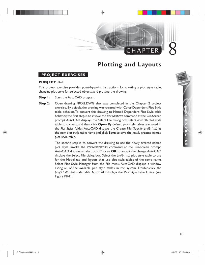
The second step is to convert the drawing to use the newly created named plot style. Invoke the CONVERTPSTYLES command at the On-screen prompt. AutoCAD displays an alert box. Choose OK to accept the change. AutoCAD displays the Select File dialog box. Select the proj8-1.stb plot style table to use for the Model tab and layouts that use plot style tables of the same name. Select Plot Style Manager from the File menu. AutoCAD displays a window listing all of the available pen style tables in the system. Double-click the proj8-1.stb plot style table. AutoCAD displays the Plot Style Table Editor (see Figure P8-1).
Plotting and Layouts
1
8
8 Chapter 43544.indd 18 Chapter 43544.indd 1 6/2/08 10:15:05 AM6/2/08 10:15:05 AM
8-2
Figure P8–1 Plot Style Table Editor dialog box
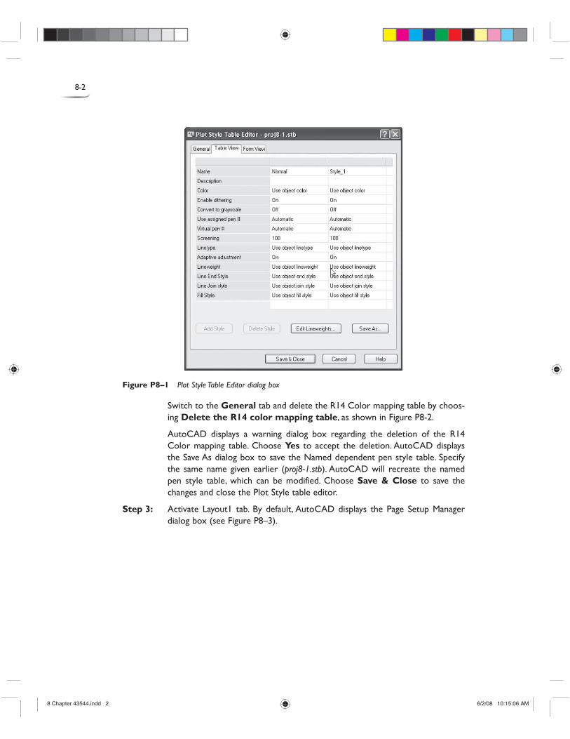
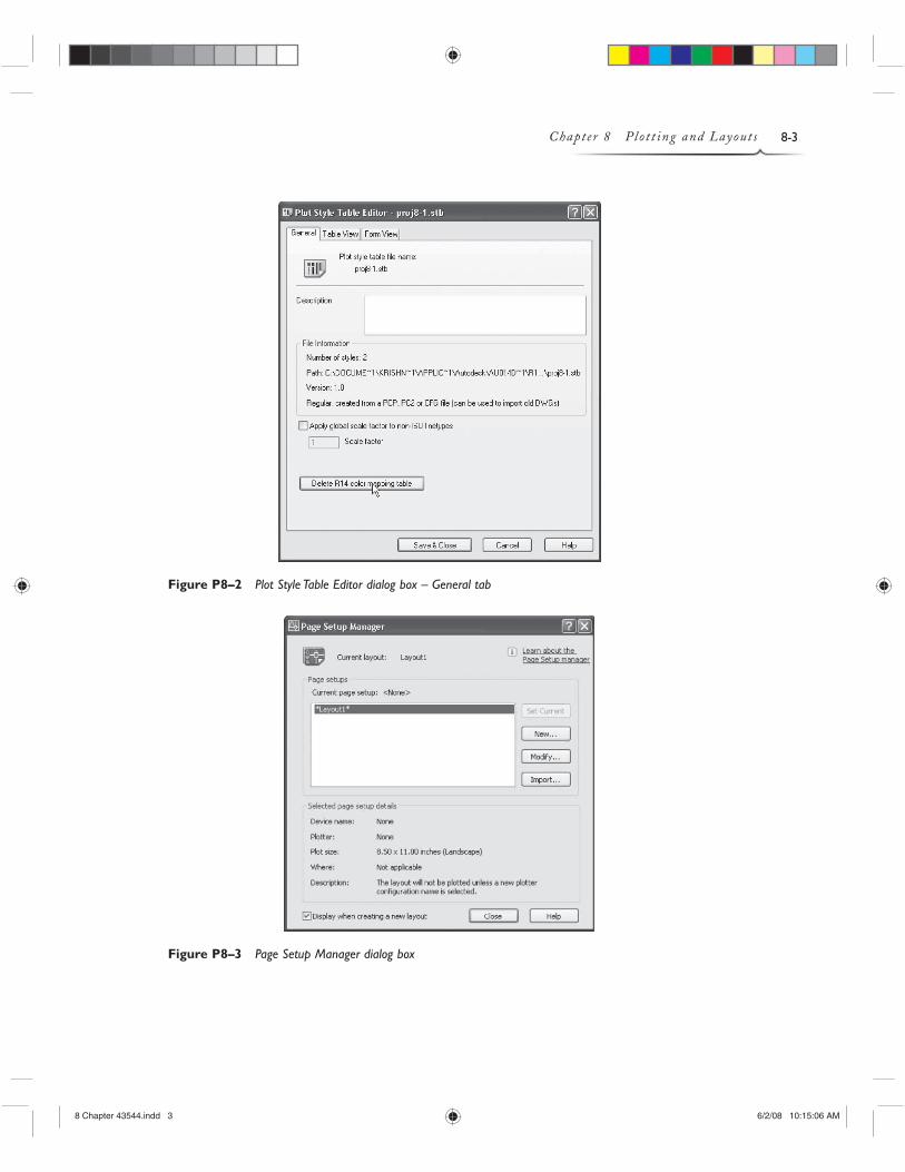
Switch to the General tab and delete the R14 Color mapping table by choos-ing Delete the R14 color mapping table, as shown in Figure P8-2.
AutoCAD displays a warning dialog box regarding the deletion of the R14 Color mapping table. Choose Yes to accept the deletion. AutoCAD displays the Save As dialog box to save the Named dependent pen style table. Specify the same name given earlier (proj8-1.stb). AutoCAD will recreate the named pen style table, which can be modified. Choose Save & Close to save the changes and close the Plot Style table editor.
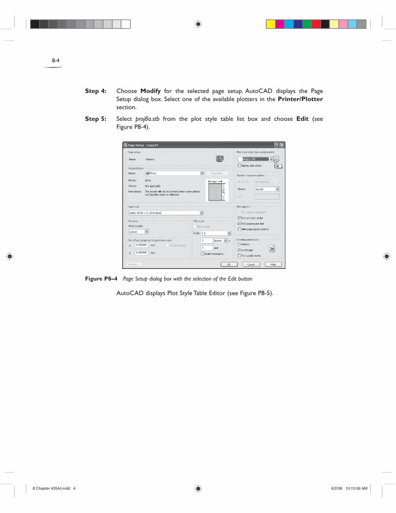
Step 3: Activate Layout1 tab. By default, AutoCAD displays the Page Setup Manager dialog box (see Figure P8–3).
8 Chapter 43544.indd 28 Chapter 43544.indd 2 6/2/08 10:15:06 AM6/2/08 10:15:06 AM
8-3Chapter 8 Plot t ing and Layouts
Figure P8–2 Plot Style Table Editor dialog box – General tab
Figure P8–3 Page Setup Manager dialog box
8 Chapter 43544.indd 38 Chapter 43544.indd 3 6/2/08 10:15:06 AM6/2/08 10:15:06 AM
8-4
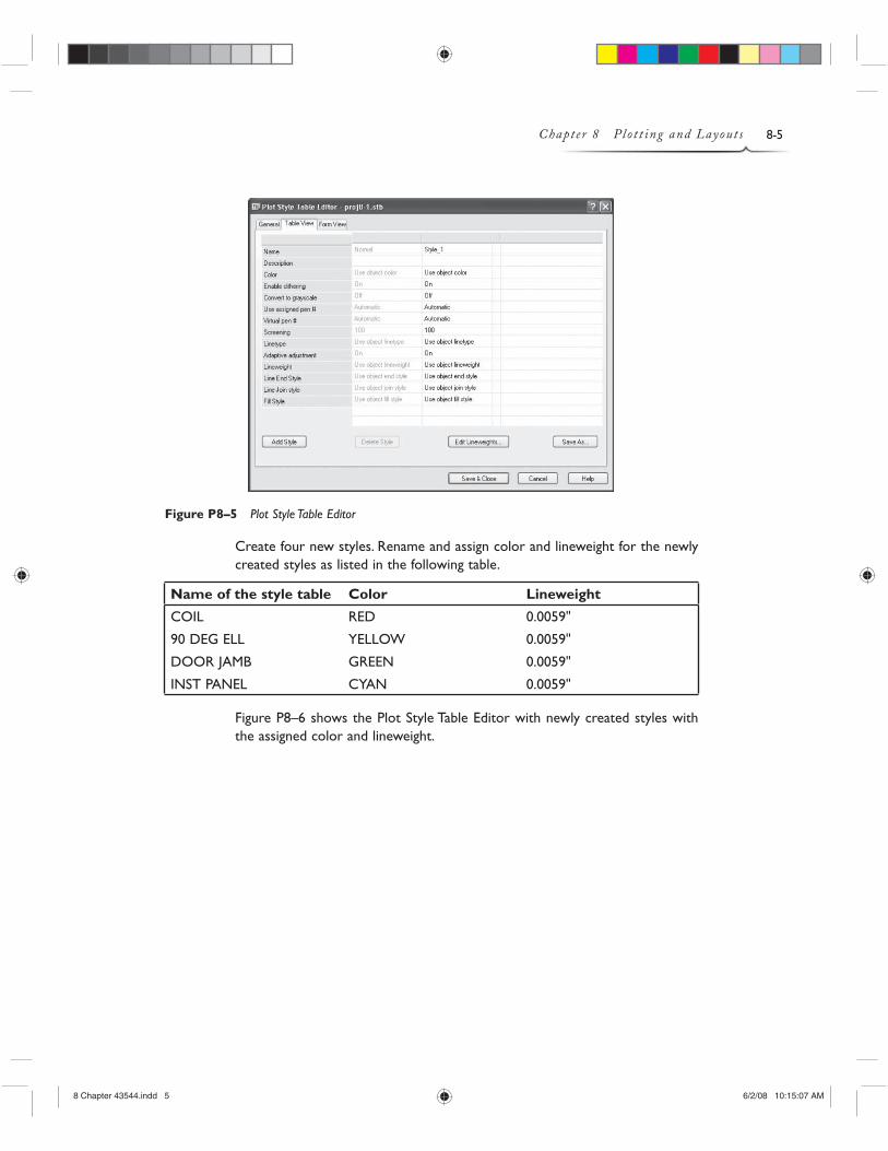
Step 4: Choose Modify for the selected page setup. AutoCAD displays the Page Setup dialog box. Select one of the available plotters in the Printer/Plotter section.
Step 5: Select proj8a.stb from the plot style table list box and choose Edit (see Figure P8-4).
Figure P8–4 Page Setup dialog box with the selection of the Edit button
AutoCAD displays Plot Style Table Editor (see Figure P8-5).
8 Chapter 43544.indd 48 Chapter 43544.indd 4 6/2/08 10:15:06 AM6/2/08 10:15:06 AM
8-5Chapter 8 Plot t ing and Layouts
Figure P8–5 Plot Style Table Editor
Create four new styles. Rename and assign color and lineweight for the newly created styles as listed in the following table.
Name of the style table Color Lineweight
COIL RED 0.0059"
90 DEG ELL YELLOW 0.0059"
DOOR JAMB GREEN 0.0059"
INST PANEL CYAN 0.0059"
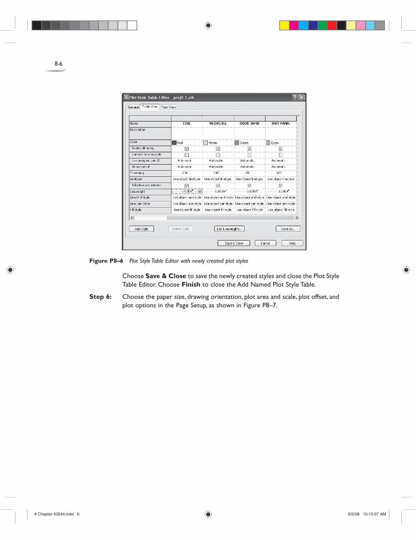
Figure P8–6 shows the Plot Style Table Editor with newly created styles with the assigned color and lineweight.
8 Chapter 43544.indd 58 Chapter 43544.indd 5 6/2/08 10:15:07 AM6/2/08 10:15:07 AM
8-6
Figure P8–6 Plot Style Table Editor with newly created plot styles
Choose Save & Close to save the newly created styles and close the Plot Style Table Editor. Choose Finish to close the Add Named Plot Style Table.
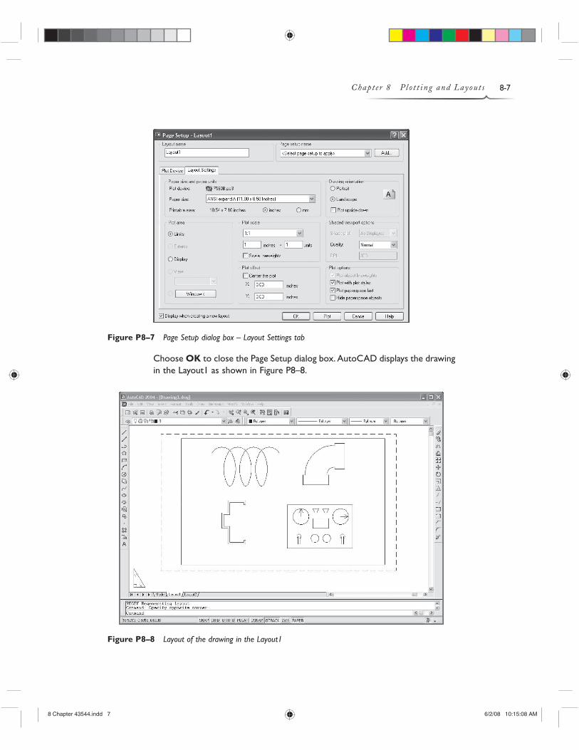
Step 6: Choose the paper size, drawing orientation, plot area and scale, plot offset, and plot options in the Page Setup, as shown in Figure P8–7.
8 Chapter 43544.indd 68 Chapter 43544.indd 6 6/2/08 10:15:07 AM6/2/08 10:15:07 AM
8-7Chapter 8 Plot t ing and Layouts
Figure P8–7 Page Setup dialog box – Layout Settings tab
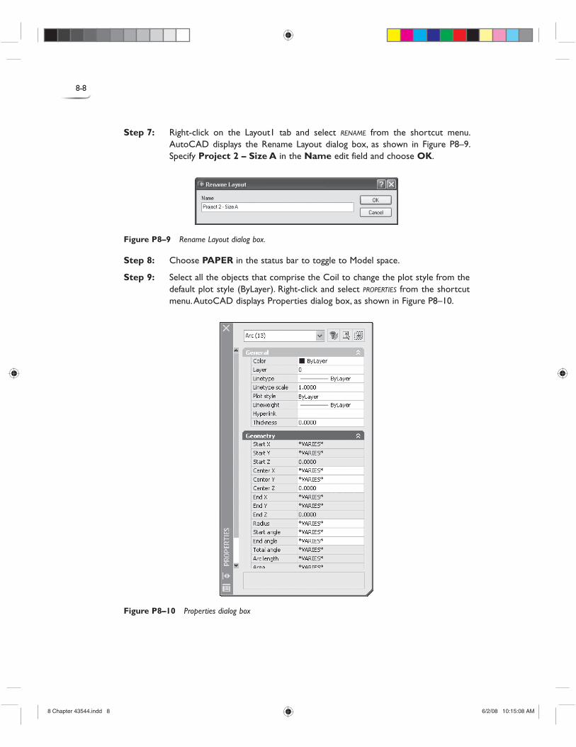
Choose OK to close the Page Setup dialog box. AutoCAD displays the drawing in the Layout1 as shown in Figure P8–8.
Figure P8–8 Layout of the drawing in the Layout1
8 Chapter 43544.indd 78 Chapter 43544.indd 7 6/2/08 10:15:08 AM6/2/08 10:15:08 AM
8-8
Step 7: Right-click on the Layout1 tab and select RENAME from the shortcut menu. AutoCAD displays the Rename Layout dialog box, as shown in Figure P8–9. Specify Project 2 – Size A in the Name edit field and choose OK.
Figure P8–9 Rename Layout dialog box.
Step 8: Choose PAPER in the status bar to toggle to Model space.
Step 9: Select all the objects that comprise the Coil to change the plot style from the default plot style (ByLayer). Right-click and select PROPERTIES from the shortcut menu. AutoCAD displays Properties dialog box, as shown in Figure P8–10.
Figure P8–10 Properties dialog box
8 Chapter 43544.indd 88 Chapter 43544.indd 8 6/2/08 10:15:08 AM6/2/08 10:15:08 AM
8-9Chapter 8 Plot t ing and Layouts
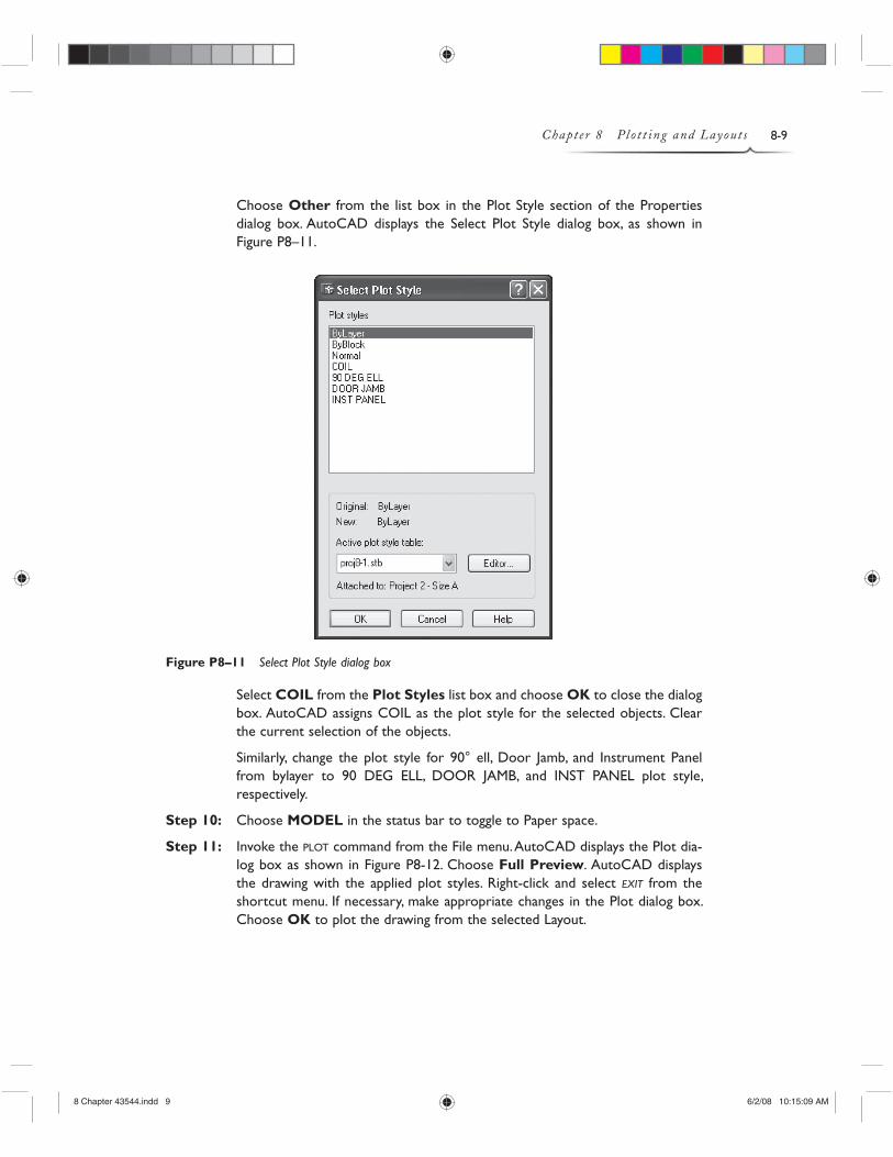
Choose Other from the list box in the Plot Style section of the Properties dialog box. AutoCAD displays the Select Plot Style dialog box, as shown in Figure P8–11.
Figure P8–11 Select Plot Style dialog box
Select COIL from the Plot Styles list box and choose OK to close the dialog box. AutoCAD assigns COIL as the plot style for the selected objects. Clear the current selection of the objects.
Similarly, change the plot style for 90° ell, Door Jamb, and Instrument Panel from bylayer to 90 DEG ELL, DOOR JAMB, and INST PANEL plot style, respectively.
Step 10: Choose MODEL in the status bar to toggle to Paper space.
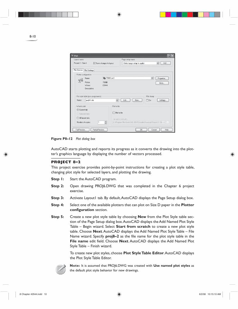
Step 11: Invoke the PLOT command from the File menu. AutoCAD displays the Plot dia-log box as shown in Figure P8-12. Choose Full Preview. AutoCAD displays the drawing with the applied plot styles. Right-click and select EXIT from the shortcut menu. If necessary, make appropriate changes in the Plot dialog box. Choose OK to plot the drawing from the selected Layout.
8 Chapter 43544.indd 98 Chapter 43544.indd 9 6/2/08 10:15:09 AM6/2/08 10:15:09 AM
8-10
Figure P8–12 Plot dialog box
AutoCAD starts plotting and reports its progress as it converts the drawing into the plot-ter’s graphics language by displaying the number of vectors processed.
PROJECT 8–2 This project exercise provides point-by-point instructions for creating a plot style table, changing plot style for selected layers, and plotting the drawing.
Step 1: Start the AutoCAD program.
Step 2: Open drawing PROJ6.DWG that was completed in the Chapter 6 project exercise.
Step 3: Activate Layout1 tab. By default, AutoCAD displays the Page Setup dialog box.
Step 4: Select one of the available plotters that can plot on Size D paper in the Plotter configuration section.
Step 5: Create a new plot style table by choosing New from the Plot Style table sec-tion of the Page Setup dialog box. AutoCAD displays the Add Named Plot Style Table – Begin wizard. Select Start from scratch to create a new plot style table. Choose Next. AutoCAD displays the Add Named Plot Style Table – File Name wizard. Specify proj8–2 as the file name for the plot style table in the File name edit field. Choose Next. AutoCAD displays the Add Named Plot Style Table – Finish wizard.
To create new plot styles, choose Plot Style Table Editor. AutoCAD displays the Plot Style Table Editor.
Note: It is assumed that PROJ6.DWG was created with Use named plot styles as the default plot style behavior for new drawings.
8 Chapter 43544.indd 108 Chapter 43544.indd 10 6/2/08 10:15:10 AM6/2/08 10:15:10 AM
8-11Chapter 8 Plot t ing and Layouts
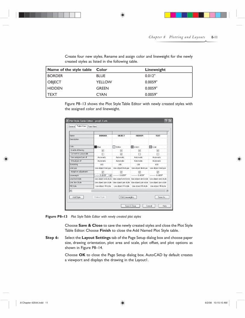
Create four new styles. Rename and assign color and lineweight for the newly created styles as listed in the following table.
Name of the style table Color Lineweight
BORDER BLUE 0.012"
OBJECT YELLOW 0.0059"
HIDDEN GREEN 0.0059"
TEXT CYAN 0.0059"
Figure P8–13 shows the Plot Style Table Editor with newly created styles with the assigned color and lineweight.
Figure P8–13 Plot Style Table Editor with newly created plot styles
Choose Save & Close to save the newly created styles and close the Plot Style Table Editor. Choose Finish to close the Add Named Plot Style table.
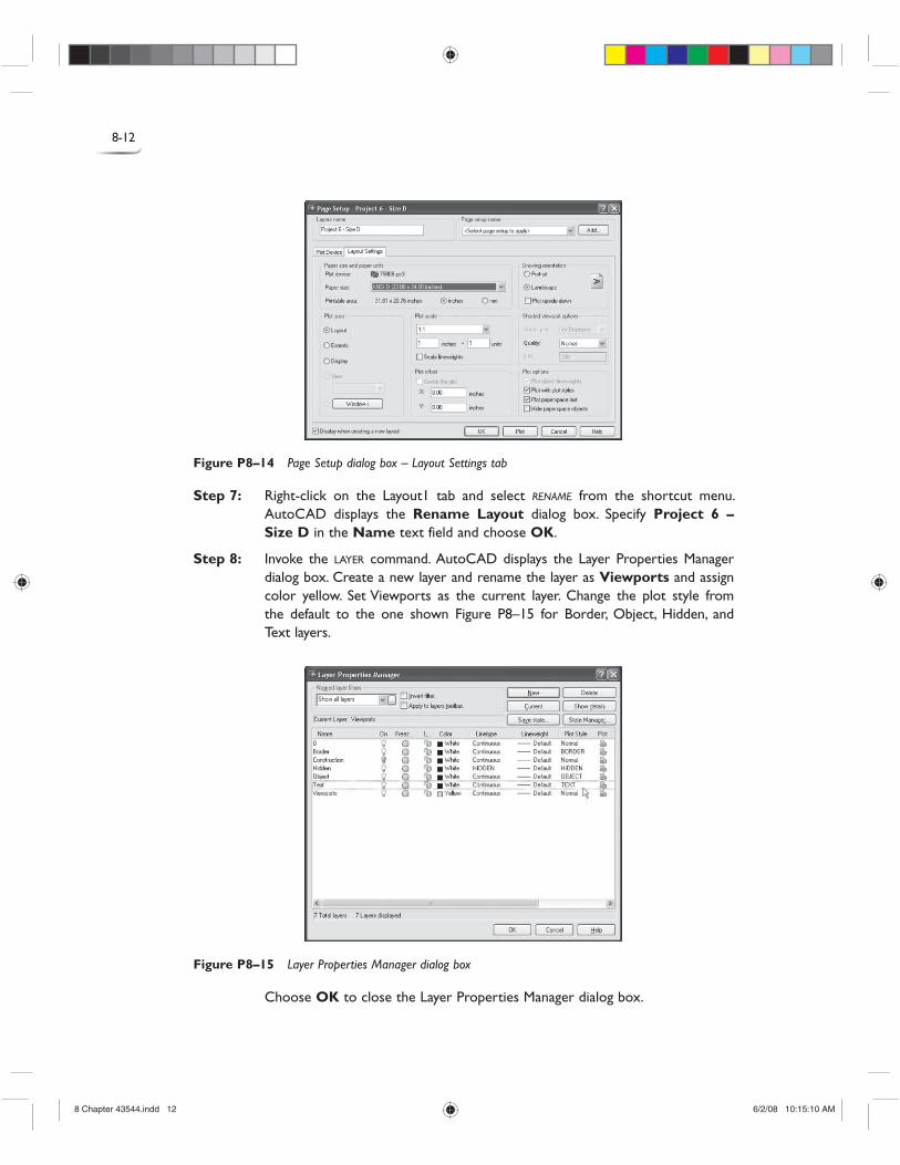
Step 6: Select the Layout Settings tab of the Page Setup dialog box and choose paper size, drawing orientation, plot area and scale, plot offset, and plot options as shown in Figure P8–14.
Choose OK to close the Page Setup dialog box. AutoCAD by default creates a viewport and displays the drawing in the Layout1.
8 Chapter 43544.indd 118 Chapter 43544.indd 11 6/2/08 10:15:10 AM6/2/08 10:15:10 AM
8-12
Figure P8–14 Page Setup dialog box – Layout Settings tab
Step 7: Right-click on the Layout1 tab and select RENAME from the shortcut menu. AutoCAD displays the Rename Layout dialog box. Specify Project 6 – Size D in the Name text field and choose OK.
Step 8: Invoke the LAYER command. AutoCAD displays the Layer Properties Manager dialog box. Create a new layer and rename the layer as Viewports and assign color yellow. Set Viewports as the current layer. Change the plot style from the default to the one shown Figure P8–15 for Border, Object, Hidden, and Text layers.
Figure P8–15 Layer Properties Manager dialog box
Choose OK to close the Layer Properties Manager dialog box.
8 Chapter 43544.indd 128 Chapter 43544.indd 12 6/2/08 10:15:10 AM6/2/08 10:15:10 AM
8-13Chapter 8 Plot t ing and Layouts
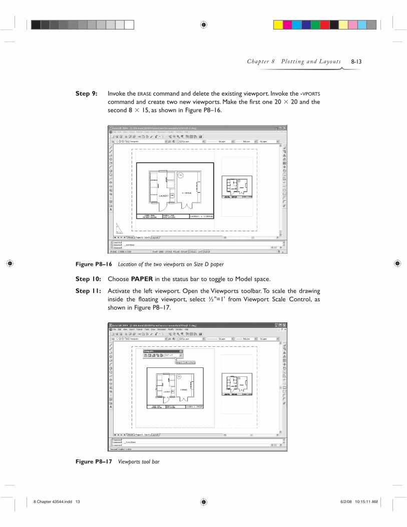
Step 9: Invoke the ERASE command and delete the existing viewport. Invoke the -VPORTS command and create two new viewports. Make the first one 20 � 20 and the second 8 � 15, as shown in Figure P8–16.
Figure P8–16 Location of the two viewports on Size D paper
Step 10: Choose PAPER in the status bar to toggle to Model space.
Step 11: Activate the left viewport. Open the Viewports toolbar. To scale the drawing inside the floating viewport, select ½"=1' from Viewport Scale Control, as shown in Figure P8–17.
Figure P8–17 Viewports tool bar
8 Chapter 43544.indd 138 Chapter 43544.indd 13 6/2/08 10:15:11 AM6/2/08 10:15:11 AM
8-14
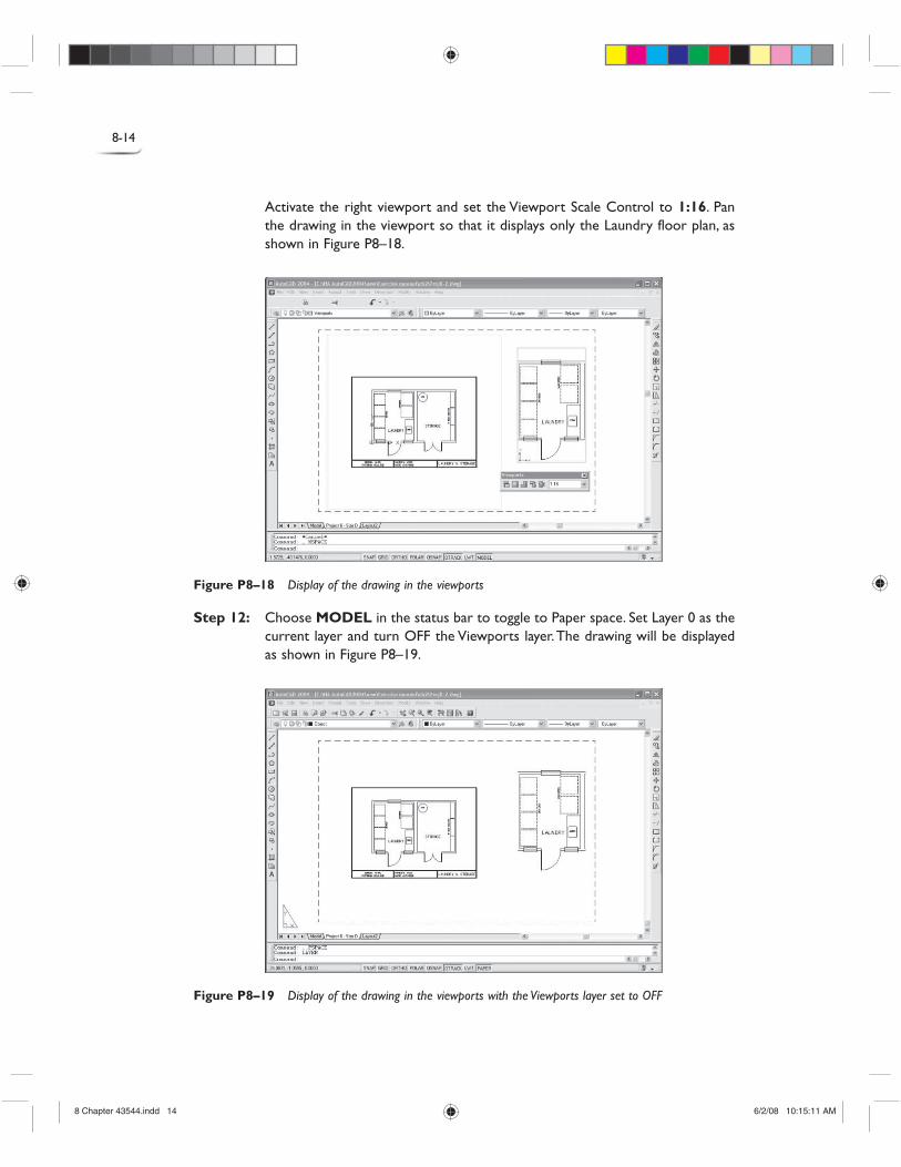
Activate the right viewport and set the Viewport Scale Control to 1:16. Pan the drawing in the viewport so that it displays only the Laundry floor plan, as shown in Figure P8–18.
Figure P8–18 Display of the drawing in the viewports
Step 12: Choose MODEL in the status bar to toggle to Paper space. Set Layer 0 as the current layer and turn OFF the Viewports layer. The drawing will be displayed as shown in Figure P8–19.
Figure P8–19 Display of the drawing in the viewports with the Viewports layer set to OFF
8 Chapter 43544.indd 148 Chapter 43544.indd 14 6/2/08 10:15:11 AM6/2/08 10:15:11 AM
8-15Chapter 8 Plot t ing and Layouts
Step 13: Invoke the PLOT command from the File menu. AutoCAD displays the Plot dialog box. Choose Full Preview. AutoCAD displays the drawing with the applied plot styles. Right-click and select EXIT from the shortcut menu. If neces-sary, make appropriate changes in the Plot dialog box. Choose OK to plot the drawing from the selected Layout.
AutoCAD starts plotting and reports its progress, as it converts the draw-ing into the plotter’s graphics language, by displaying the number of vectors processed.
8 Chapter 43544.indd 158 Chapter 43544.indd 15 6/2/08 10:15:11 AM6/2/08 10:15:11 AM
general E
XE
RC
IS
Eproject
EX
ER
CI
SE
8-16
EXERCISE 8–1 Open the EX7–4 drawing that was completed in Chapter 7. Plot the drawing on size C paper at a scale of 1:2.
EXERCISE 8–2 Open the EX7–5 drawing that was completed in Chapter 7. Select the appropriate paper size to plot the drawing at a scale of 1:4.
EXERCISE 8–3 Open the EX7–8 drawing that was completed in Chapter 7. Create a layout to plot the drawing on size C paper at a scale of 1"=1'0". Add a title block and plot the drawing.
EXERCISE 8–4 Open the EX7–9 drawing that was completed in Chapter 7. Select the appropriate paper size to plot the drawing at a scale of ½"=1'0".
EXERCISE 8–5 Open the EX7–13 drawing that was completed in Chapter 7. Select an appropriate paper size to plot the drawing at a scale of ½"=1'0".
EXERCISE 8–6 Open the EX7–17 drawing that was completed in Chapter 7. Plot the drawing on size B paper and scale to fit.
EXERCISE 8–7 Open the EX7–20 drawing that was completed in Chapter 7. Plot the drawing on size C paper and scale to fit.
EXERCISE 8–8 Open the EX7–20 drawing that was completed in Chapter 7. Plot the drawing on size A paper and scale to Fit.
8 Chapter 43544.indd 168 Chapter 43544.indd 16 6/2/08 10:15:11 AM6/2/08 10:15:11 AM