Embed Size (px)
Citation preview
Plots, Calculations and Graphics Tools (PCG2)
Software Transfer Request Presentation
Presented by
PCG2 Software Development
November 8, 2010
u -
Why An Advisory System
- Through time, the need to provide tools that quickly and efficiently facilitate data analysis continues to be a constant, and many times growing demand.
- Engineers must perform data analysis to: confirm system performance, requirement conformance, understand behavior, perform feasibility studies, trends, trouble-shooting and comparisons, potentially across vehicles and missions.
- Data analysis needs may be near real-time, post-test or historical. They may support activities in the Firing Room or in the office area and the users continue to express needs for flexible and agile capabilities.
- Objective Evidence of positions in the form of analyzed data are readily used in program decision-making throughout the centers on a daily basis.
- Manual analysis and interpretation of data like that performed by the Shuttle Program 25+ years ago can be a huge impact on the Engineering workforce and they constantly request methods to help and assist in performing this obligation.
November 2010 Page 1
The PCG2 Tool Meets These Needs and More
USA
PCG2 Advisory System
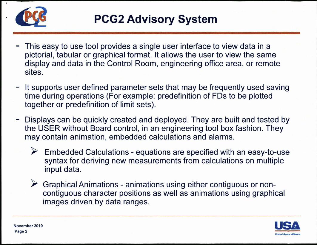
- This easy to use tool provides a single user interface to view data in a pictorial, tabular or graphical format. It allows the user to view the same display and data in the Control Room, engineering office area, or remote sites.
- It supports user defined parameter sets that may be frequently used saving time during operations (For example: predefinition of FDs to be plotted together or predefinition of limit sets).
- Displays can be quickly created and deployed. They are built and tested by the USER without Board control, in an engineering tool box fashion. They may contain animation, embedded calculations and alarms.
~ Embedded Calculations - equations are specified with an easy-to-use syntax for deriving new measurements from calculations on multiple input data.
~ Graphical Animations - animations using either contiguous or noncontiguous character positions as well as animations using graphical images driven by data ranges.
November 2010 Page 2
USA
PCG2 Advisory System
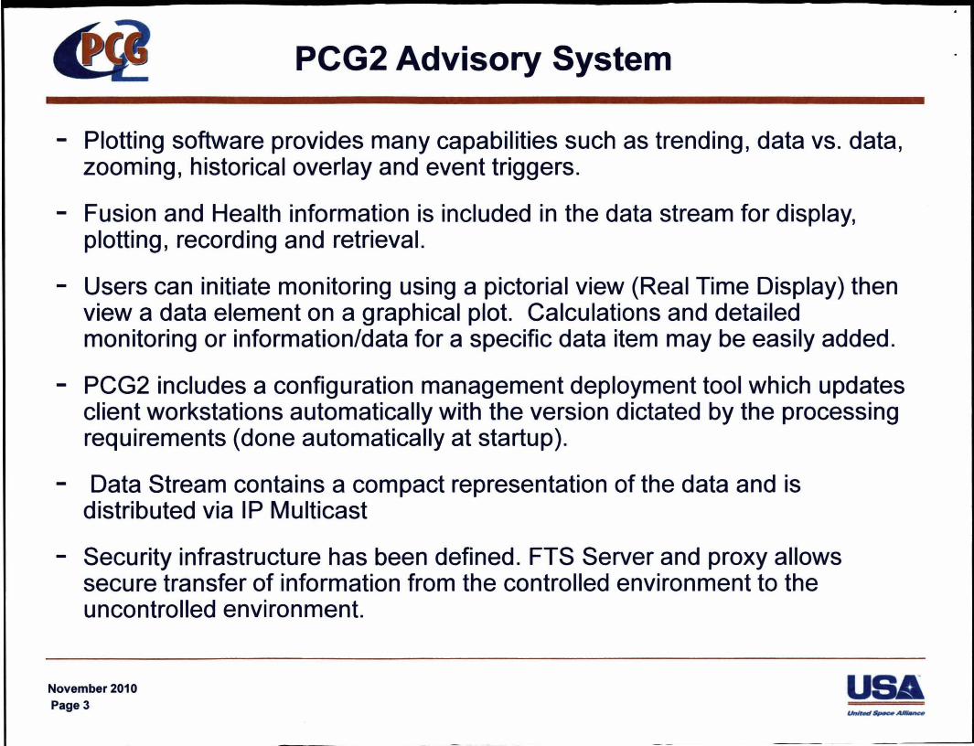
- Plotting software provides many capabilities such as trending, data vs. data, zooming, historical overlay and event triggers.
- Fusion and Health information is included in the data stream for display, plotting, recording and retrieval.
- Users can initiate monitoring using a pictorial view (Real Time Display) then view a data element on a graphical plot. Calculations and detailed monitoring or information/data for a specific data item may be easily added.
- PCG2 includes a configuration management deployment tool which updates client workstations automatically with the version dictated by the processing requirements (done automatically at startup).
- Data Stream contains a compact representation of the data and is distributed via IP Multicast
- Security infrastructure has been defined. FTS Server and proxy allows secure transfer of information from the controlled environment to the uncontrolled environment.
November 2010 Page 3
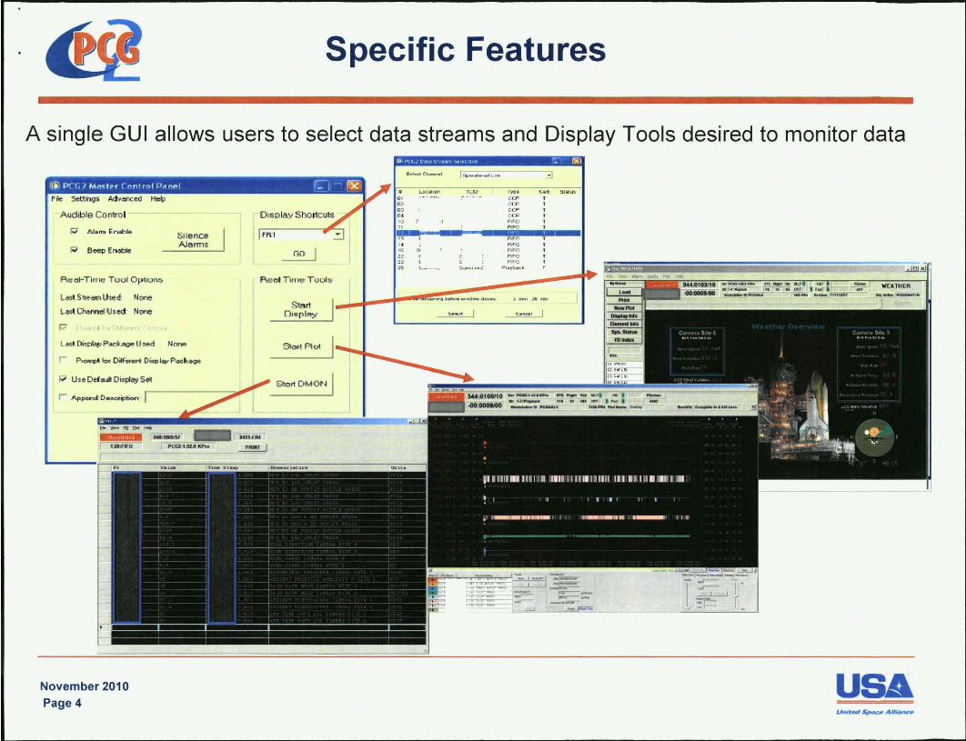
Specific Features
A single GUI allows users to select data streams and Display Tools desired to monitor data
iii "CC,JMi'1<tPr ront rol~i\n .. 1 ~I -- [g1 File Setti"los Adv/IIIC ed He\)
Audib le Control - D isp lay Shortcuts
Beep Enoble
F\eol-Time Tool Optoon:;
lAs~ SI'~4m U$td: None
lAs~ o.anne! Ulect None
Silence N81IT1s
LA,. D~1>I!e> Pa",,- U ted No"",
r P,O"""fot DiIFw_ O"P~PoO(;"_
u • • DelauI, O~ay S~
r A ppend OOOCfpOom: I
November 2010 Page 4
FRl
s""' '" ~ I I Start DM ON I
.. I. I. 22 O. 25
~~~ .... I 1000 ........ ..a L_ 3 LOC:!tIl;W\ l C I) ,'''', eo. SlalUS
CCP T C'CP , c CP eel> f lro 1",1"0
FI,g "'0 i> F"IFO nrc ' IFO
t.-.. , .• _ ~, •• o! ~1tIltd
USA
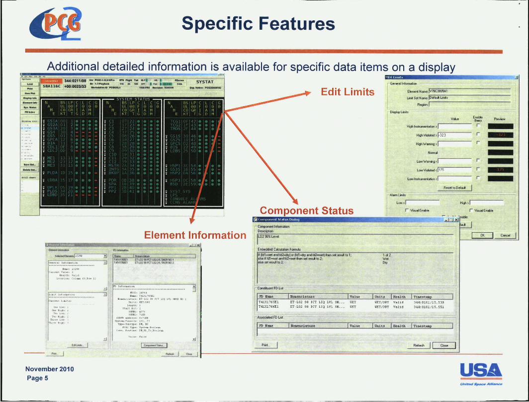
Specific Features
Additional detailed information is available for specific data items on a display 344:0211108
5BA1l6C _ :0023133
:"'I~t V.tlle;
Kf'tltk ".hd.
pcet-uu KPr. ITS,.... , .. "'1"~ ".U ........ Df'CeoM..
-" ..
Element Information
loCIUUIl' Coha" r.~,II,", 1~
.... 1._: I
BaoI K1GbI I ~~I.
T'II> "1~1 :: nlleC I.<Mr ~ tH Mlt;lt.l l
.:J
11)1;): Z .. NA .... : r 400'tI!L1
1I c:8U>C!awut IT w.l ,. tl" 110 lV1. II .IkJ I &lu: lln'UY
t.cDtJU,lll t un. Bl'-i 1
UllJlli " 071 I l: <HQ
etI,,", 4041.,.": 0_'71,11
KG: t'yp_: S,.tA.~b"'h_
C<QIW' , t11t_r.t_' O_aIlDl._
Edit Limits
Component Status
fGeneral l~orlMtion
Elemert N arne: JV76C309iii'1 I LiniI s .. Nome:l::lo:-oI:-.... -:c:-Limito:-· ,.... ------------
l _ . Aegion:l
OispiayLinil.
H;g, Instrumentation > I HighVooIated >I-323
H;g, W.",ing > I Norm.al
Low W.rning <I LowVooIated <1175
Lowlnslr...-...t.lion <1
Value
Reselto Oefd
rAlolmLiniI,
Lowd
r VrsualEnobie
Enable Preview B .. p
r r r
r r r
C~I~a~ -------~-----------------------------------------_, Description
IL02 98'.: Level
Embedded CoIcuIation Fa..w
II Ifdl·wet one! fd2cdryJ 01 Ifd1 cdry one! Id2_J then ... result to 1; .~. J fd1.wet ond fd2·w .. then ... r ..... to 2: eke set I~ to 3;
Nomenclature
IT- L02 98 PCT LIQ LVL SN... \lIT IT- L0 2 98 PCT LIQ LVL SN. . . \lIT
Nomenclature:
1012 W .. Ory
Valid VET/DRY Valid
344: 0 101/ 15. 539 344: 0101 /1 5. 551
OK Concel
---~ I~~ ~ 1~~ ______________ ~;;p;rn~";;~======================================~;;A~~~.m~~1 ~I ;;~~;;~ ____________ _
November 2010 PageS
USA
Specific Features
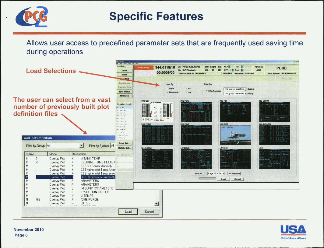
Allows user access to predefined parameter sets that are frequently used saving time during operations
Load Selections
The user can select from a vast number of previously built plot definition files
Load plot Definition !"'""~
Filter by Group: I All
Overlay Plot Overlay Plot Overlay Plot Overlay Plot Overlay Plot
H tv
3 Filter by System:
tv J2 ECO Sensor Anomaly tv )2 Engine Inlet Temp tv )2 Engine Inlet Temp
D.erl'>', F'lol ':, A 6.RAMETERS A 6.RAMETERS
00:0009100
L .... ay
r Nomo
Vo< !'CCll-l.U.' Kl'r. STS ~llht To_ 'Doll"
.... 1-7:l'IoyI>ock 11' r JS r 113 ~1' __ 10 !'CClOAL5 1451_4 R.vI ..... : 8/t1l2OO6
FIIIoray
I <no system specified ::J System r ESAPockogo
I <no group specified> 3 Group
I I Page 180tM ::J I «provI .... 1 Load Cine"
PLBD
Overlay Plot Overlay Plot Overlay Plot Overlay Plot Overlay Plot Overlay Plot Overlay Plot
L MBURPPARAMETERS ~ ____ -L __________ ~ ______________________________________________________ ~
GE
November 2010 Page 6
L P SUCTION LINE CD H A TEMPS NONE PURGE
.OTS .. .:.l Load Cancel I
Specific Features
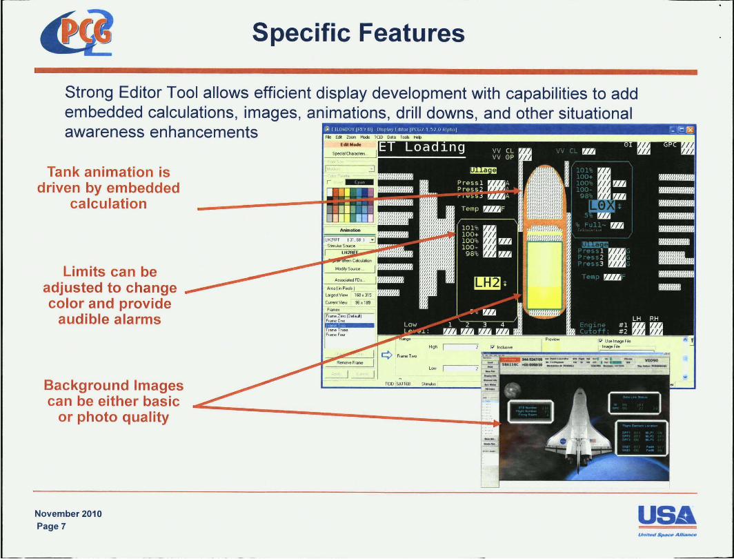
Strong Editor Tool allows efficient display development with capabilities to add embedded calculations, images, animations, drill downs, and other situational awareness enhancements
Tank animation is driven by embedded
calculation
Limits can be adjusted to change color and provide
audible alarms
Background Images can be either basic
or photo quality
November 2010 Page 7
Frame Tl'wee Ffo!JMeFcu
Low I ~
TOO SAl1611 5 ........
USA UnJt~ $pM» Allu.nc.
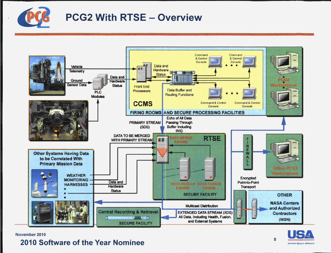
PCG2 With RTSE - Overview
Front End Processors
Data and Hardware
Status
Data Buffer and Routing Functions
Command & Control .---.1'1
Coonsoloi!
• • •
• • • CCMS Command & Conltol
ConaoIe Comma'1d & Control
Console
FIRING ROOMIS J\ND CURE PROCESS
PRIMARY STREAM (SOS)
FACILITIES
F I R
Other Systems Having Data to be Correlated With Primary Mission Data
..... --1 E ............ "1 W
November 2010
WEATHER MONITORING -t---~ .... ~~ HARNESSES -t--~~ii-' • . ----.... --~=~-~
It.
Encrypted Point-to-Point
Transport
OTHER
NASA Centers ,....-------------.. ... _ .... __ Multk:a __ at_Di8IrbItion _____ ...... LJf-Io~.J._ ... and Authorized Central Ral:ftl'ldII'Ia EXTENDED DATA STREAM (XDS) Contractors
secuRI! FACILITY ..... ...J All Data, Including Health, Fualon, (NISN)
and External System.
USA 2010 Software of the Year Nominee 8
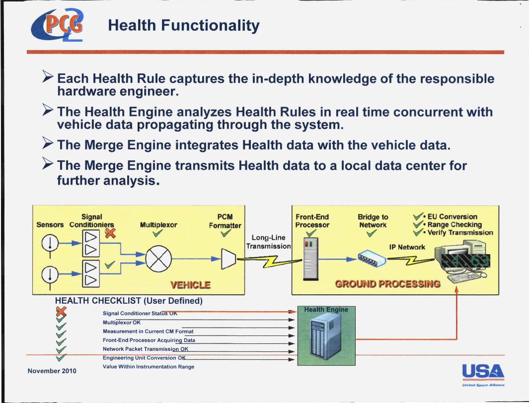
Health Functionality
~ Each Health Rule captures the in-depth knowledge of the responsible hardware engineer.
~ The Health Engine analyzes Health Rules in real time concurrent with vehicle data propagating through the system.
~ The Merge Engine integrates Health data with the vehicle data.
~ The Merge Engine transmits Health data to a local data center for further analysis.
-- -----
Signal Sensors Conditioniers Multiplexor
HEALTH CHECKLIST (User Defined)
PCM Fonnatter
Front·End Processor
Signal Conditioner ~ ... t;TnTr--------~1
Multiplexor OK •
Measurement in Current CM Format • ---------------.. Front-End Processor Acquiri_ng_Da'-'-'-ta ______________ ••
Network Packet Transmission OK •
November 2010 Value Within Instrumentation Range
-------
Bridge to Network
• EU Conversion • Range Checking • Verify Transmission
IP Network
USA UnJl~ $pM» AU~
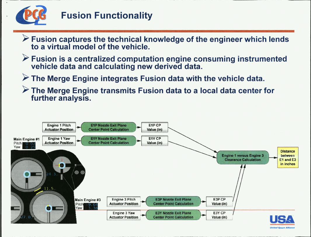
Fusion Functionality
~ Fusion captures the technical knowledge of the engineer which lends to a virtual model of the vehicle.
~ Fusion is a centralized computation engine consuming instrumented vehicle data and calculating new derived data.
~ The Merge Engine integrates Fusion data with the vehicle data.
~ The Merge Engine transmits Fusion data to a local data center for further analysis.
Main Engine #1 PitCh. Yaw
Engine 1 Pitch Actuator Position
Engine 1 Yaw Actuator Position
Engine 3 Pit.ch Actuator Position
E1PCP Value (in)
E1YCP Value (in)
E3P Nozzle exit PIIM CenIIr PoInt c.IcuIl1Ion
Engine 1 ftI'8U8 EngIne S CI......:e CelGaMan
EJPCP Value (In)
Distance between
E1 and E3 in inches
E3Y Nozzle exit Plane Center Polm calcUll1Ion
E3YCP Value (In) USA
November 2010
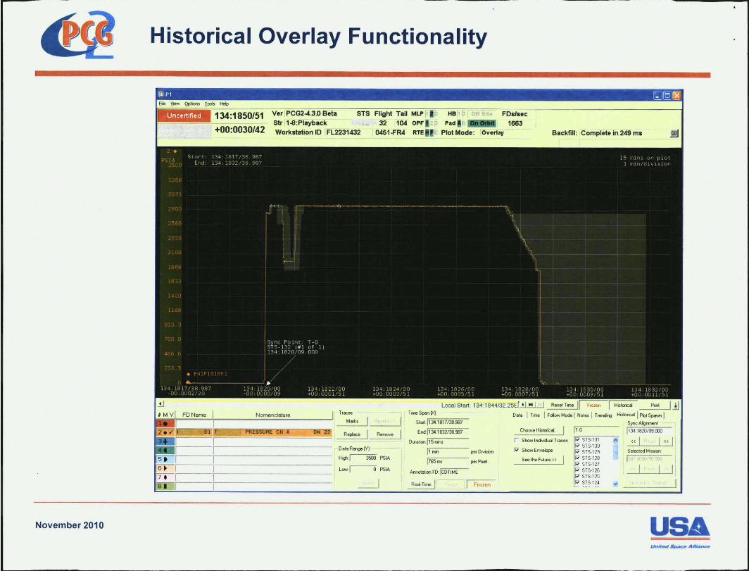
Historical Overlay Functionality
134:1850/51
+00:0030/42
Ver PCG2-4.3.0 Beta STS Flight Tail MLP k
32 104 OPF Str 1-S:Playback Workstation 10 FL2231432
Tfaces
Marks
0451-FR4
Replace Remove
OoloRo_M
H;gh:~PSIA
Low.r-o PSIA
RTE
Tine Span !Xl Slart: r.ll"'34:-::181=7/"'38"".98;;:;7,
£nd:II34:1832138.987
ouroloo:115 rrim
1r.1-="",;:-· --- per OMs;on
1765"" per P>rel
Annotoloo FD:~
I Frozen
Backfill : Complete in 249 ms
Choose H;,toricoL IT.O
HistOficai
H;"OI;c.1 I Plot Spown I Sync AIgnment
1134.1820109.00J
r Show ln<Mdua1 1races r.=--::-:ST"'S"7·13==-1-----, P S1S·13O
« I I » I P Show £nvelope STS.I29
Seethe FutUfe » STS·l28 S1S·127 S1S·126
P SI S·125 SIS ·124
Se!ect:ed Mission:
USA Un/rMl ~AHJAnaI
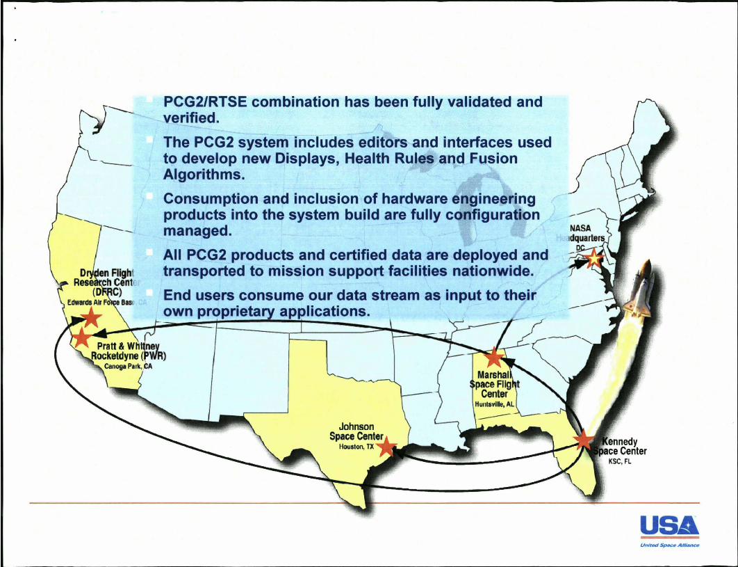
PCG2/RTSE combination has been fully validated and verified.
The PCG2 system includes editors and interfaces used to develop new Displays, Health Rules and Fusion Algorithms.
Consumption and inclusion of hardware engineering products into the system build are fully configuration managed.
All PCG2 products and certified data are deployed and transported to mission support facilities nationwide.
End users consume our data stream as input to their own proprieta a lications.
USA
Conclusion
- PCG2 supports extensive and regular engineering needs that are both planned and unplanned.
- PCG2 supports the ability to compare, contrast and perform ad hoc data mining over the entire domain of a program's test data.
- There has been growing demand for non-LPS system analysis capability. Experimentation has been successful on the PCG2 merges of external non-LPS data into its data stream today.
- Infrastructure exists today with mature and evolved services.
- Questions and Discussion
November 2010 Page 13
u
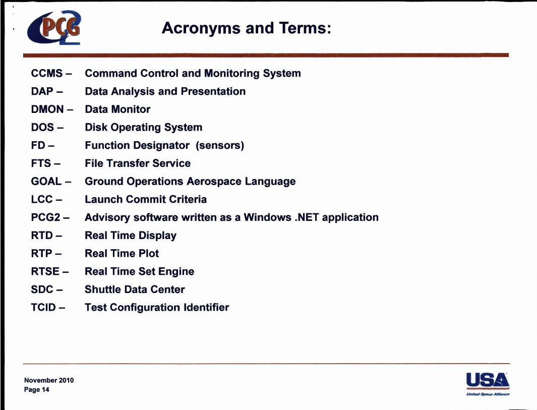
CCMS
DAP
DMON
DOS
FD
FTS
GOAL
LCC
PCG2-
RTD
RTP
RTSE
SDC
TCID-
November 2010 Page 14
Acronyms and Terms:
Command Control and Monitoring System
Data Analysis and Presentation
Data Monitor
Disk Operating System
Function Designator (sensors)
File Transfer Service
Ground Operations Aerospace Language
Launch Commit Criteria
Advisory software written as a Windows .NET application
Real Time Display
Real Time Plot
Real Time Set Engine
Shuttle Data Center
Test Configuration Identifier