Embed Size (px)
Citation preview
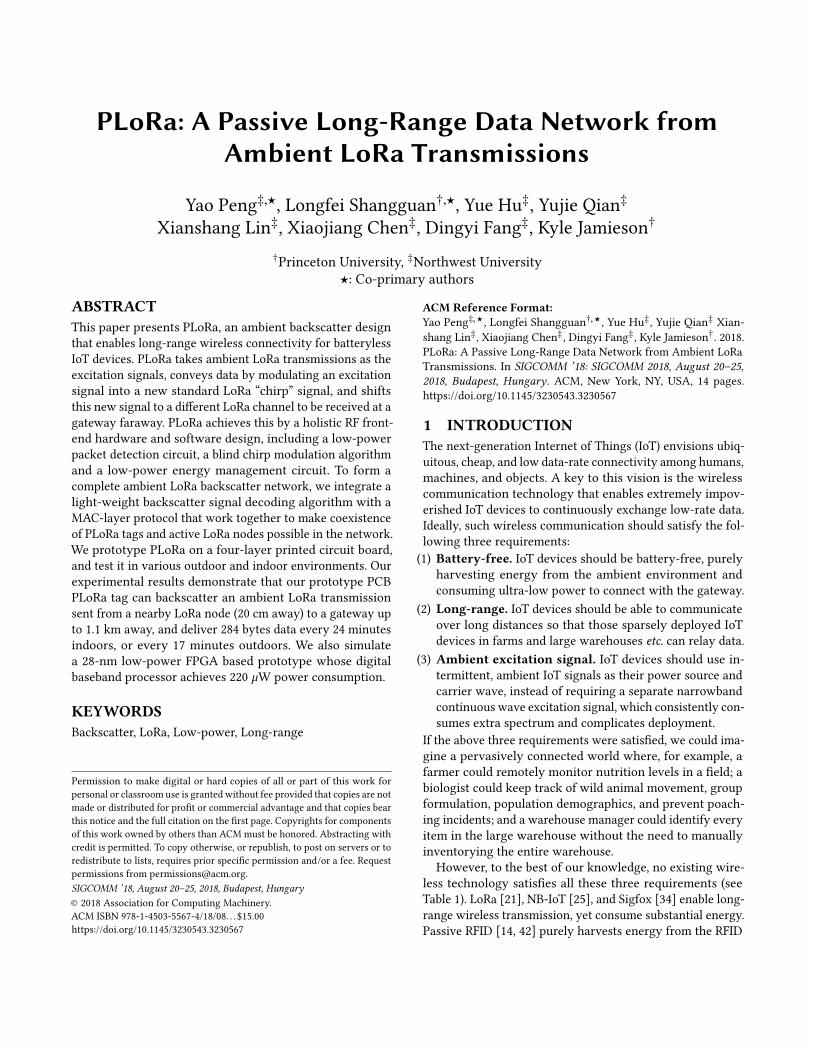
PLoRa: A Passive Long-Range Data Network fromAmbient LoRa Transmissions
Yao Peng‡,⋆, Longfei Shangguan†,⋆, Yue Hu‡, Yujie Qian‡Xianshang Lin‡, Xiaojiang Chen‡, Dingyi Fang‡, Kyle Jamieson†
†Princeton University, ‡Northwest University⋆: Co-primary authors
ABSTRACTThis paper presents PLoRa, an ambient backscatter designthat enables long-range wireless connectivity for batterylessIoT devices. PLoRa takes ambient LoRa transmissions as theexcitation signals, conveys data by modulating an excitationsignal into a new standard LoRa “chirp” signal, and shiftsthis new signal to a different LoRa channel to be received at agateway faraway. PLoRa achieves this by a holistic RF front-end hardware and software design, including a low-powerpacket detection circuit, a blind chirp modulation algorithmand a low-power energy management circuit. To form acomplete ambient LoRa backscatter network, we integrate alight-weight backscatter signal decoding algorithm with aMAC-layer protocol that work together to make coexistenceof PLoRa tags and active LoRa nodes possible in the network.We prototype PLoRa on a four-layer printed circuit board,and test it in various outdoor and indoor environments. Ourexperimental results demonstrate that our prototype PCBPLoRa tag can backscatter an ambient LoRa transmissionsent from a nearby LoRa node (20 cm away) to a gateway upto 1.1 km away, and deliver 284 bytes data every 24 minutesindoors, or every 17 minutes outdoors. We also simulatea 28-nm low-power FPGA based prototype whose digitalbaseband processor achieves 220 µW power consumption.
KEYWORDSBackscatter, LoRa, Low-power, Long-range
Permission to make digital or hard copies of all or part of this work forpersonal or classroom use is granted without fee provided that copies are notmade or distributed for profit or commercial advantage and that copies bearthis notice and the full citation on the first page. Copyrights for componentsof this work owned by others than ACMmust be honored. Abstracting withcredit is permitted. To copy otherwise, or republish, to post on servers or toredistribute to lists, requires prior specific permission and/or a fee. Requestpermissions from [email protected] ’18, August 20–25, 2018, Budapest, Hungary© 2018 Association for Computing Machinery.ACM ISBN 978-1-4503-5567-4/18/08. . . $15.00https://doi.org/10.1145/3230543.3230567
ACM Reference Format:Yao Peng‡,⋆, Longfei Shangguan†,⋆, Yue Hu‡, Yujie Qian‡ Xian-shang Lin‡, Xiaojiang Chen‡, Dingyi Fang‡, Kyle Jamieson†. 2018.PLoRa: A Passive Long-Range Data Network from Ambient LoRaTransmissions. In SIGCOMM ’18: SIGCOMM 2018, August 20–25,2018, Budapest, Hungary. ACM, New York, NY, USA, 14 pages.https://doi.org/10.1145/3230543.3230567
1 INTRODUCTIONThe next-generation Internet of Things (IoT) envisions ubiq-uitous, cheap, and low data-rate connectivity among humans,machines, and objects. A key to this vision is the wirelesscommunication technology that enables extremely impov-erished IoT devices to continuously exchange low-rate data.Ideally, such wireless communication should satisfy the fol-lowing three requirements:(1) Battery-free. IoT devices should be battery-free, purely
harvesting energy from the ambient environment andconsuming ultra-low power to connect with the gateway.
(2) Long-range. IoT devices should be able to communicateover long distances so that those sparsely deployed IoTdevices in farms and large warehouses etc. can relay data.
(3) Ambient excitation signal. IoT devices should use in-termittent, ambient IoT signals as their power source andcarrier wave, instead of requiring a separate narrowbandcontinuous wave excitation signal, which consistently con-sumes extra spectrum and complicates deployment.
If the above three requirements were satisfied, we could ima-gine a pervasively connected world where, for example, afarmer could remotely monitor nutrition levels in a field; abiologist could keep track of wild animal movement, groupformulation, population demographics, and prevent poach-ing incidents; and a warehouse manager could identify everyitem in the large warehouse without the need to manuallyinventorying the entire warehouse.However, to the best of our knowledge, no existing wire-
less technology satisfies all these three requirements (seeTable 1). LoRa [21], NB-IoT [25], and Sigfox [34] enable long-range wireless transmission, yet consume substantial energy.Passive RFID [14, 42] purely harvests energy from the RFID
SIGCOMM ’18, August 20–25, 2018, Budapest, Hungary Y. Peng et al.
Table 1: Summary of existing backscatter systems.
Technology Batteryfree
Longrange
Ambientexcitation
Passive RFID [14, 42]√
Ambient backscatter [19]√ √
Turbo charging [28]√ √
Wi-Fi backscatter [17]√ √
Passive Wi-Fi [18]√
HitchHike [46]√
FS-Backscatter [49]√
FM Backscatter [41]√ √
LoRa backscatter [38]√ √
LoRea [40]√
FreeRider [48]√
PLoRa√ √ √
reader, but only works over a limited range (up to 30 m [7]).LoRa backscatter [38] and LoRea [40] are low-power andlong-range, but both require a dedicated continuous wavetransmitter to send an excitation signal—a constant sinu-soidal tone—as the power source and the carrier for theirbackscatter transmissions. Deployment of such a special-pur-posed excitation signal generator increases installation andmaintenance costs (due to the need to plug such a deviceinto the electricity grid), and consumes wireless spectrum,especially outdoors or over large geographic areas.LoRaWAN networks have been successfully deployed in bo-th urban and rural areas for smart city (e.g., smart lighting,air quality monitoring, parking, and vehicle management)and industrial applications (e.g., shipping and transportation,smart farming and livestock management etc.) [22]. Gate-way and LoRa nodes in these LoRaWAN networks regularlyexchange data using chirp-modulated signals that can bedecoded at very low signal-to-noise ratio (SNR), thus in prin-ciple serving as an excellent excitation signal for long-rangebackscatter. This observation leads us to propose PLoRa, aPassive LoRa communication technology that enables long-range connectivity for IoT devices based on ambient excita-tion, without the need for a dedicated excitation source. ThePLoRa tag is battery-free, harvests energy from both radiosignals and ambient light, and can communicate with bothactive LoRa nodes and gateways over long distances in threedistinct ways (as also shown in Figure 1):
(a) Conventional backscatter. The LoRa gateway directlyinquires the PLoRa tag to retrieve its sensor readings. Thenthe tag uses its low-power electronics to modulate the imped-ance of its antenna, signaling information back to the gate-way at a frequency (uplink) different from the gateway’s
LoRa gateway
PLoRa tag
backscatter
overhearing
Active LoRa nodes
backscatter
backscatteroverhearing
uplink
downlink
�a� �b� �c�
Figure 1: The PLoRa tag (a.) takes downlink LoRachirps as the excitation signal and modulates theminto standard uplink LoRa chirps; (b.) overhears am-bient uplink LoRa chirps, using them as excitation topiggyback sensed data to the gateway; and (c.) over-hears ambient downlink LoRa chirps, using them asexcitation to piggyback sensing data to an active LoRanode in the field.
downlink transmission. The gateway then listens to this fre-quency and decodes the backscatter data at the same time asthe downlink transmission.
(b) Opportunistic uplink piggybacking. An active LoRanode located in proximity to, but not at exactly the samelocation as the PLoRa tag may transmit its own sensor read-ings on the uplink to the LoRa gateway. At this time, thePLoRa tag can modulate the active LoRa node’s transmissionto piggyback its own sensor readings to the gateway. Thegateway receives both sensor readings on separate chan-nels (frequencies)—thus the PLoRa tag expands the spatialcoverage of the LoRaWAN.
(c) Opportunistic downlink piggybacking. This scenariois the converse of the preceding, with the LoRa gateway trans-mitting commands to active LoRa nodes on the downlink(e.g., to configure their sensing) but the PLoRa tag may be outof the backscatter range from the LoRa gateway, and so thePLoRa node instead detects the gateway’s transmission anduses it to piggyback data to a nearby active LoRa node that isin contact with the gateway. The active LoRa node can thenforward these transmissions on to the gateway, resulting indata collection from both node and tag.In this way, we form a hybrid LoRa network with the
existing LoRa infrastructure cooperating with PLoRa nodesto forward data to the gateway in an extensively expandedconfiguration compared to conventional LoRa networks.To put this idea into practice, however, there are many
significant challenges. First, since the PLoRa tag is battery-free, it should consume an ultra-low amount of power duringwhich it is idle, listening to detect an incoming LoRa packet.The standard LoRa packet detection algorithm first multipliesthe incoming signal with a down chirp, then performs an FFT
PLoRa: A Passive Long-Range Data Network fromAmbient LoRa Transmissions SIGCOMM ’18, August 20–25, 2018, Budapest, Hungary
on the result and searches for FFT peaks. However, generat-ing a down chirp requires the help of a power-hungary digitalto analog converter (DAC) and a voltage-controlled oscilla-tor (VCO), thus violating the purpose of using backscatter.Our solution is to reduce the sampling rate of the incomingsignals and perform cross correlation for packet detection(§3.1), because power consumption decreases monotonicallywith the sampling rate.
Second, unlike the sinusoidal tone used in RFID and mostother backscatter systems [18, 38, 40], the excitation signalin PLoRa is the normal downlink and uplink LoRa chirpsthat convey data and change over time. It is thus challengingto modulate this time-varying excitation signal into anotherstandard LoRa chirp for backscatter. Our solution is to let thePLoRa node generate an FSK-modulated baseband signal andmultiply it with the incoming LoRa chirp. The multiplicationcauses a frequency shift of the incoming chirp by BW /2and −BW /2, where BW is the LoRa chirp bandwidth. Thekey observation is that the in-band part of these two shiftedchirps, when spliced together, will form a new, standard LoRachirp (§3.2) that conveys sensing data and is receivable overa long distance.Third, given the large energy demands of the computa-
tional and communication tasks, the battery-free PLoRa tagwill soon drain its energy and stop working, which will causecomplete loss of data stored in its volatile memory. To solvethis challenge, we put forward a holistic energy managementhardware design (§4). This hardware works as a finite-statemachine to manage the node’s state transitions, completingtasks under tight time constraints before energy starvationleads to complete loss of volatile memory, and minimizingenergy leakage caused by the static energy consumption ofFPGA and sensors on the PCB board when the node is incharging. Our hardware design uses passive componentssuch as resistors, capacitors and low-power active compo-nents like switches, and hence is ultra-low power in nature.Apart from these three core techniques, we also propose
a light-weight backscatter signal decoding algorithm (§3.3)and a MAC-layer protocol (§5) to facilitate the coexistenceof PLoRa tags and commercial active LoRa nodes in a Lo-RaWAN. To demonstrate the feasibility of our design, weprototype PLoRa on a four-layer printed circuit board (PCB)using commercial off-the-shelf circuit components and aMicrosemi’s IGLOO nano low-power FPGA [10] (§6). Weevaluate the performance of PLoRa in various indoor andoutdoor settings and in different weather conditions. The ex-tensive field studies demonstrate that PLoRa’s transmissionscan be successfully decoded on the receiver over a distanceof 600 m and 1.1 km (depending on the gateway hardware)in outdoor place and cross two concrete walls in an indooroffice building, while consuming only 2.591 mW energy inPCB implementation. We also simulate a 28-nm low-power
FPGA based prototype whose digital baseband processorconsumes 220 µW energy.
Contributions. The primary contributions of this paper are:• Proposing a holistic hardware-software co-design to achievelow-power long-range backscatter communication. The hard-ware prototype takes an ambient LoRa signal as an excitationsignal and employs a novel blind chirp modulation algorithmto transmit data. We further design a low-power current gatecircuit to prevent data loss caused by energy depletion.• Implementing this hardware-software co-design on the PCBboard and evaluating its performance through a long-term(three months) experiment in both indoor and outdoor envi-ronment. Our comprehensive experiments evaluate all threebackscatter schemes in various weather conditions includingsleet, snow, and clear days.
Limitations. This paper is an early step towards passivelong-range data networks, and there is obviously room forcontinued research. First, PLoRa’s packet detection rangeis limited to 50 m, leaving a large space for improvement.Second, PLoRa’s maximum backscatter range is highly sensi-tive to the power level of the incoming excitation. Third, theLoRa gateway needs to run a dedicated packet reception al-gorithm for backscatter packet decoding. This is not alwaysfeasible due to the limited computation resources on thoselow-end LoRa gateways. Finally, the current PLoRa designencodes one bit per LoRa symbol and thus achieves a lowdata rate. Our ongoing work is to improve the performanceof four above metrics.
Roadmap. The remainder of this paper first prepares a LoRaprimer (§2), then describes PHY-layer (§3), energy manage-ment hardware (§4), and MAC-layer design (§5). Our sys-tem’s implementation (§6) and real-world evaluation (§7)follow. §8 surveys related work. § 9 discusses limitation andfuture works. §10 concludes.
2 LORA PRIMERA typical LoRa system consists of two parts: LoRa gatewaysand LoRa nodes. The LoRa band is divided into multipleuplink and downlink channels: the gateway communicateswith LoRa nodes using downlink channels, while the LoRanodes send data to the gateway over uplink channels.LoRa adopts chirp spread spectrum (CSS) modulation,
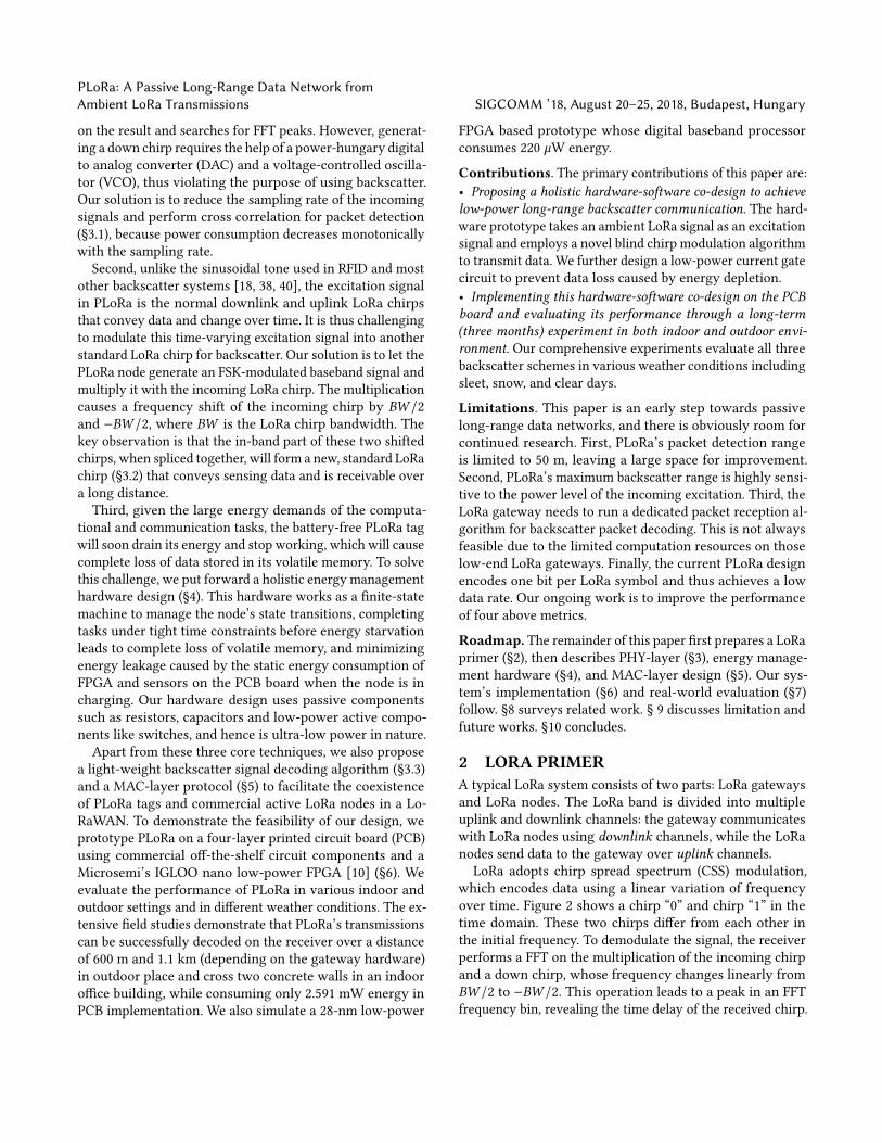
which encodes data using a linear variation of frequencyover time. Figure 2 shows a chirp “0” and chirp “1” in thetime domain. These two chirps differ from each other inthe initial frequency. To demodulate the signal, the receiverperforms a FFT on the multiplication of the incoming chirpand a down chirp, whose frequency changes linearly fromBW /2 to −BW /2. This operation leads to a peak in an FFTfrequency bin, revealing the time delay of the received chirp.
SIGCOMM ’18, August 20–25, 2018, Budapest, Hungary Y. Peng et al.B
W/2
-BW
/2
f
t
bit “0”
base chirp
f
t
bit “1”
delay
BW
/2-B
W/2
Figure 2: LoRa chirp signal “0” and chirp signal “1”: allchirp signals are a slice of a continuous base chirp us-ing an equal-length window (shadowed area), but dif-fering from each other in the initial frequency. BW isthe bandwidth.
By tracking the location of the FFT peak, the receiver de-modulates the chirp signal. As the chirp fully utilizes itsentire allocated bandwidth to encode data, it is more robustto channel noise, Doppler and multi-path effects. The LoRanode changes the spreading factor to control the number ofbits encoded in the chirp symbol.
3 PLORA PHYSICAL LAYERWe now describe the PLoRa PHY-layer design including in-coming excitation packet detection (§3.1), backscatter signalmodulation (§3.2) on the PLoRa tag, and demodulation (§3.3)on the LoRa gateway. We denote the LoRa chirp emitted bythe gateway and the active LoRa node as the active LoRachirp and that backscattered by the PLoRa tag as the passiveLoRa chirp.
3.1 Packet DetectionConventional backscatter systems [14, 18, 38, 40, 42] omitpacket detection on the backscatter tag because the exci-tation signal they use is a continuous sinusoidal tone sentfrom a nearby dedicated excitation generator. However ina PLoRa network, the excitation signal is the intermittentLoRa traffic itself, so the PLoRa tag needs to detect this LoRatraffic, synchronize with its LoRa symbols, and use it as thecarrier for backscatter. The standard LoRa packet detectionalgorithm is prohibitive for PLoRa tag due to its substantialenergy consumption: it requires a high-power DAC and aVCO, and performs the computation-intensive FFT.
Our approach is to reduce the sampling rate of the in-coming signals and perform cross-correlation between theseincoming signals and the pre-stored preambles for packet de-tection and synchronization. It is safe to reduce the samplingrate to some degree because the PLoRa tag does not decodethe incoming signals and thus is not restricted by the Nyquist-Shannon sampling theorem. We reduce the sampling rate forpacket detection because its power consumption decreasesmonotonically with the sampling rate [50]. We describe howpacket detection works as a signal passes through the circuit
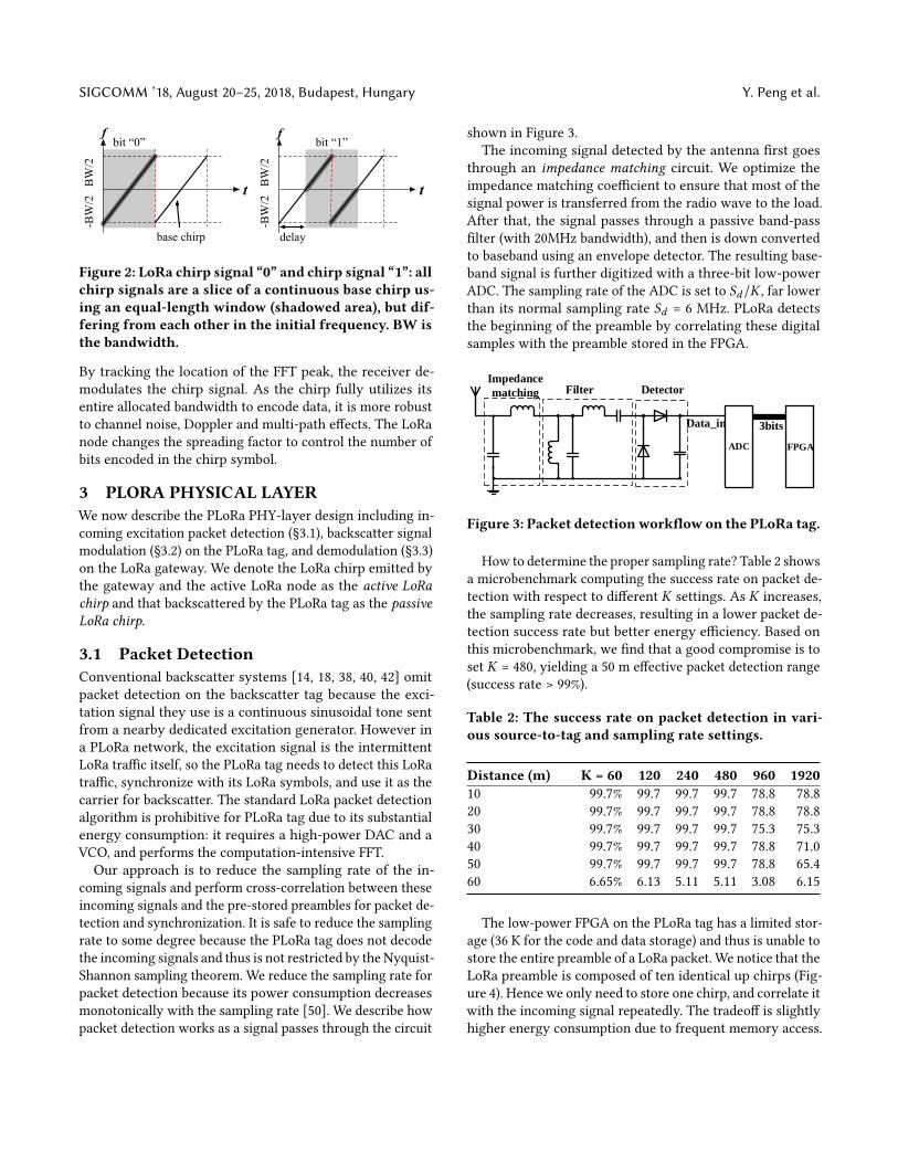
shown in Figure 3.The incoming signal detected by the antenna first goes
through an impedance matching circuit. We optimize theimpedance matching coefficient to ensure that most of thesignal power is transferred from the radio wave to the load.After that, the signal passes through a passive band-passfilter (with 20MHz bandwidth), and then is down convertedto baseband using an envelope detector. The resulting base-band signal is further digitized with a three-bit low-powerADC. The sampling rate of the ADC is set to Sd/K , far lowerthan its normal sampling rate Sd = 6 MHz. PLoRa detectsthe beginning of the preamble by correlating these digitalsamples with the preamble stored in the FPGA.
FPGA
3bits
ADC
Filter Detector
Data_in
Impedance
matching
Figure 3: Packet detection workflow on the PLoRa tag.
How to determine the proper sampling rate? Table 2 showsa microbenchmark computing the success rate on packet de-tection with respect to different K settings. As K increases,the sampling rate decreases, resulting in a lower packet de-tection success rate but better energy efficiency. Based onthis microbenchmark, we find that a good compromise is toset K = 480, yielding a 50 m effective packet detection range(success rate > 99%).
Table 2: The success rate on packet detection in vari-ous source-to-tag and sampling rate settings.
Distance (m) K = 60 120 240 480 960 192010 99.7% 99.7 99.7 99.7 78.8 78.820 99.7% 99.7 99.7 99.7 78.8 78.830 99.7% 99.7 99.7 99.7 75.3 75.340 99.7% 99.7 99.7 99.7 78.8 71.050 99.7% 99.7 99.7 99.7 78.8 65.460 6.65% 6.13 5.11 5.11 3.08 6.15
The low-power FPGA on the PLoRa tag has a limited stor-age (36 K for the code and data storage) and thus is unable tostore the entire preamble of a LoRa packet. We notice that theLoRa preamble is composed of ten identical up chirps (Fig-ure 4). Hence we only need to store one chirp, and correlate itwith the incoming signal repeatedly. The tradeoff is slightlyhigher energy consumption due to frequent memory access.
PLoRa: A Passive Long-Range Data Network fromAmbient LoRa Transmissions SIGCOMM ’18, August 20–25, 2018, Budapest, Hungary
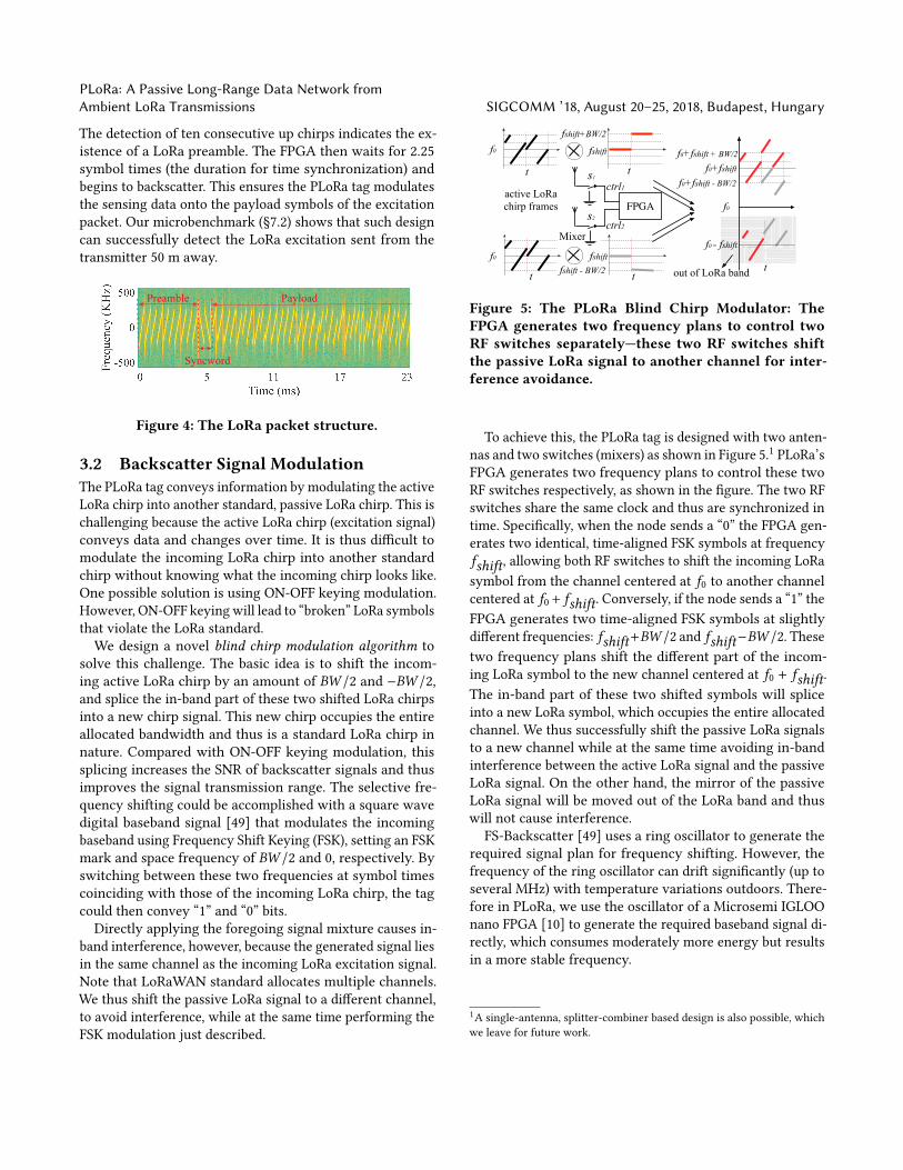
The detection of ten consecutive up chirps indicates the ex-istence of a LoRa preamble. The FPGA then waits for 2.25symbol times (the duration for time synchronization) andbegins to backscatter. This ensures the PLoRa tag modulatesthe sensing data onto the payload symbols of the excitationpacket. Our microbenchmark (§7.2) shows that such designcan successfully detect the LoRa excitation sent from thetransmitter 50 m away.
Preamble
Syncword
Payload
Figure 4: The LoRa packet structure.
3.2 Backscatter Signal ModulationThe PLoRa tag conveys information by modulating the activeLoRa chirp into another standard, passive LoRa chirp. This ischallenging because the active LoRa chirp (excitation signal)conveys data and changes over time. It is thus difficult tomodulate the incoming LoRa chirp into another standardchirp without knowing what the incoming chirp looks like.One possible solution is using ON-OFF keying modulation.However, ON-OFF keyingwill lead to “broken” LoRa symbolsthat violate the LoRa standard.We design a novel blind chirp modulation algorithm to
solve this challenge. The basic idea is to shift the incom-ing active LoRa chirp by an amount of BW /2 and −BW /2,and splice the in-band part of these two shifted LoRa chirpsinto a new chirp signal. This new chirp occupies the entireallocated bandwidth and thus is a standard LoRa chirp innature. Compared with ON-OFF keying modulation, thissplicing increases the SNR of backscatter signals and thusimproves the signal transmission range. The selective fre-quency shifting could be accomplished with a square wavedigital baseband signal [49] that modulates the incomingbaseband using Frequency Shift Keying (FSK), setting an FSKmark and space frequency of BW /2 and 0, respectively. Byswitching between these two frequencies at symbol timescoinciding with those of the incoming LoRa chirp, the tagcould then convey “1” and “0” bits.
Directly applying the foregoing signal mixture causes in-band interference, however, because the generated signal liesin the same channel as the incoming LoRa excitation signal.Note that LoRaWAN standard allocates multiple channels.We thus shift the passive LoRa signal to a different channel,to avoid interference, while at the same time performing theFSK modulation just described.
fshift
FPGA
fshift
f0
active LoRa chirp frames
f0+fshift
Mixer
f0
f0 - fshift
t
t
t
t
t
f0
out of LoRa band
s1
s2
fshift+BW/2
fshift - BW/2
f0+fshift + BW/2
f0+fshift - BW/2ctrl1
ctrl2
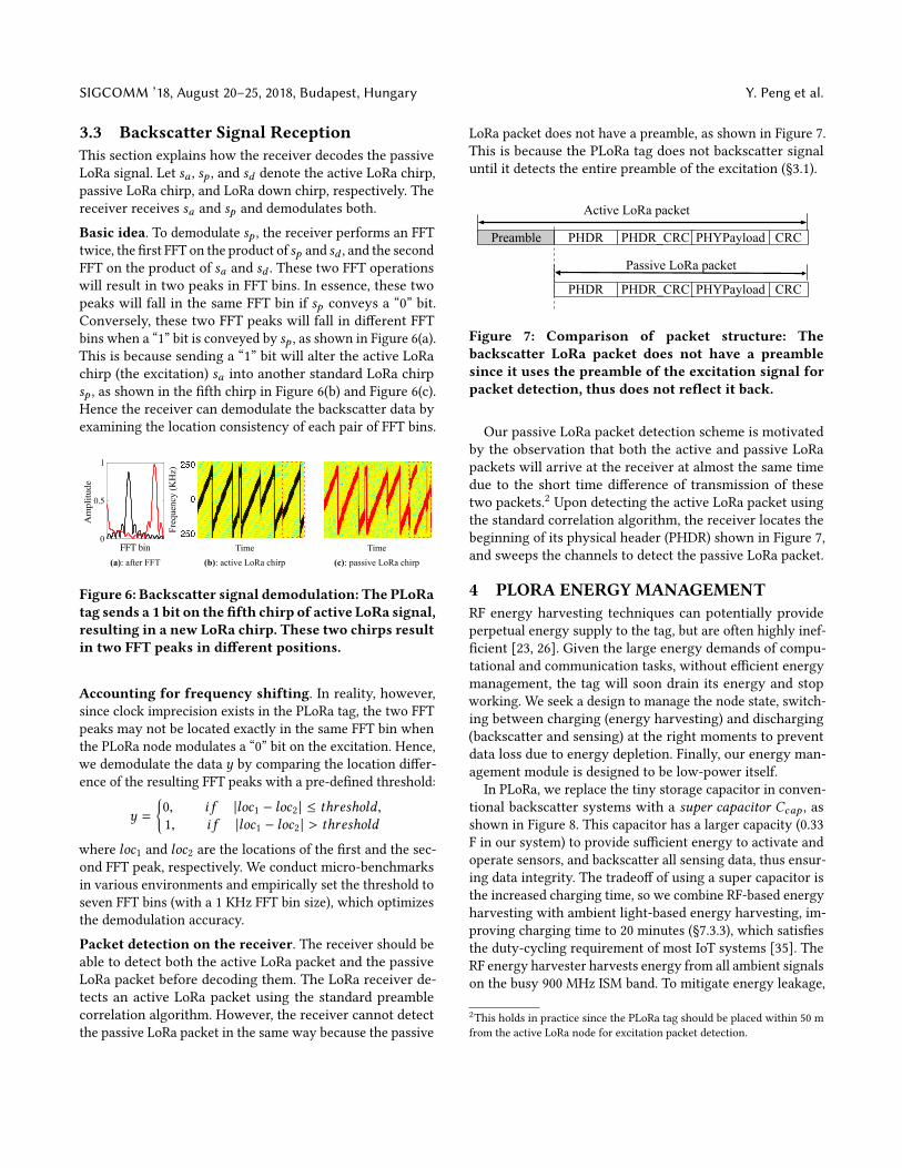
Figure 5: The PLoRa Blind Chirp Modulator: TheFPGA generates two frequency plans to control twoRF switches separately—these two RF switches shiftthe passive LoRa signal to another channel for inter-ference avoidance.
To achieve this, the PLoRa tag is designed with two anten-nas and two switches (mixers) as shown in Figure 5.1 PLoRa’sFPGA generates two frequency plans to control these twoRF switches respectively, as shown in the figure. The two RFswitches share the same clock and thus are synchronized intime. Specifically, when the node sends a “0” the FPGA gen-erates two identical, time-aligned FSK symbols at frequencyfshift, allowing both RF switches to shift the incoming LoRasymbol from the channel centered at f0 to another channelcentered at f0+ fshift. Conversely, if the node sends a “1” theFPGA generates two time-aligned FSK symbols at slightlydifferent frequencies: fshift+BW /2 and fshift−BW /2. Thesetwo frequency plans shift the different part of the incom-ing LoRa symbol to the new channel centered at f0 + fshift.The in-band part of these two shifted symbols will spliceinto a new LoRa symbol, which occupies the entire allocatedchannel. We thus successfully shift the passive LoRa signalsto a new channel while at the same time avoiding in-bandinterference between the active LoRa signal and the passiveLoRa signal. On the other hand, the mirror of the passiveLoRa signal will be moved out of the LoRa band and thuswill not cause interference.
FS-Backscatter [49] uses a ring oscillator to generate therequired signal plan for frequency shifting. However, thefrequency of the ring oscillator can drift significantly (up toseveral MHz) with temperature variations outdoors. There-fore in PLoRa, we use the oscillator of a Microsemi IGLOOnano FPGA [10] to generate the required baseband signal di-rectly, which consumes moderately more energy but resultsin a more stable frequency.
1A single-antenna, splitter-combiner based design is also possible, whichwe leave for future work.
SIGCOMM ’18, August 20–25, 2018, Budapest, Hungary Y. Peng et al.
3.3 Backscatter Signal ReceptionThis section explains how the receiver decodes the passiveLoRa signal. Let sa , sp , and sd denote the active LoRa chirp,passive LoRa chirp, and LoRa down chirp, respectively. Thereceiver receives sa and sp and demodulates both.
Basic idea. To demodulate sp , the receiver performs an FFTtwice, the first FFT on the product of sp and sd , and the secondFFT on the product of sa and sd . These two FFT operationswill result in two peaks in FFT bins. In essence, these twopeaks will fall in the same FFT bin if sp conveys a “0” bit.Conversely, these two FFT peaks will fall in different FFTbins when a “1” bit is conveyed by sp , as shown in Figure 6(a).This is because sending a “1” bit will alter the active LoRachirp (the excitation) sa into another standard LoRa chirpsp , as shown in the fifth chirp in Figure 6(b) and Figure 6(c).Hence the receiver can demodulate the backscatter data byexamining the location consistency of each pair of FFT bins.
FFT bin0
0.5
1
Am
plitu
de
Freq
uenc
y (K
Hz)
Time Time(a): after FFT (b): active LoRa chirp (c): passive LoRa chirp
Figure 6: Backscatter signal demodulation: The PLoRatag sends a 1 bit on the fifth chirp of active LoRa signal,resulting in a new LoRa chirp. These two chirps resultin two FFT peaks in different positions.
Accounting for frequency shifting. In reality, however,since clock imprecision exists in the PLoRa tag, the two FFTpeaks may not be located exactly in the same FFT bin whenthe PLoRa node modulates a “0” bit on the excitation. Hence,we demodulate the data y by comparing the location differ-ence of the resulting FFT peaks with a pre-defined threshold:
y =
{0, i f |loc1 − loc2 | ≤ threshold,1, i f |loc1 − loc2 | > threshold
where loc1 and loc2 are the locations of the first and the sec-ond FFT peak, respectively. We conduct micro-benchmarksin various environments and empirically set the threshold toseven FFT bins (with a 1 KHz FFT bin size), which optimizesthe demodulation accuracy.
Packet detection on the receiver. The receiver should beable to detect both the active LoRa packet and the passiveLoRa packet before decoding them. The LoRa receiver de-tects an active LoRa packet using the standard preamblecorrelation algorithm. However, the receiver cannot detectthe passive LoRa packet in the same way because the passive
LoRa packet does not have a preamble, as shown in Figure 7.This is because the PLoRa tag does not backscatter signaluntil it detects the entire preamble of the excitation (§3.1).
Preamble PHDR PHDR_CRC PHYPayload CRC
PHDR PHDR_CRC PHYPayload CRC
Active LoRa packet
Passive LoRa packet
Figure 7: Comparison of packet structure: Thebackscatter LoRa packet does not have a preamblesince it uses the preamble of the excitation signal forpacket detection, thus does not reflect it back.
Our passive LoRa packet detection scheme is motivatedby the observation that both the active and passive LoRapackets will arrive at the receiver at almost the same timedue to the short time difference of transmission of thesetwo packets.2 Upon detecting the active LoRa packet usingthe standard correlation algorithm, the receiver locates thebeginning of its physical header (PHDR) shown in Figure 7,and sweeps the channels to detect the passive LoRa packet.
4 PLORA ENERGY MANAGEMENTRF energy harvesting techniques can potentially provideperpetual energy supply to the tag, but are often highly inef-ficient [23, 26]. Given the large energy demands of compu-tational and communication tasks, without efficient energymanagement, the tag will soon drain its energy and stopworking. We seek a design to manage the node state, switch-ing between charging (energy harvesting) and discharging(backscatter and sensing) at the right moments to preventdata loss due to energy depletion. Finally, our energy man-agement module is designed to be low-power itself.
In PLoRa, we replace the tiny storage capacitor in conven-tional backscatter systems with a super capacitor Ccap , asshown in Figure 8. This capacitor has a larger capacity (0.33F in our system) to provide sufficient energy to activate andoperate sensors, and backscatter all sensing data, thus ensur-ing data integrity. The tradeoff of using a super capacitor isthe increased charging time, so we combine RF-based energyharvesting with ambient light-based energy harvesting, im-proving charging time to 20 minutes (§7.3.3), which satisfiesthe duty-cycling requirement of most IoT systems [35]. TheRF energy harvester harvests energy from all ambient signalson the busy 900 MHz ISM band. To mitigate energy leakage,
2This holds in practice since the PLoRa tag should be placed within 50 mfrom the active LoRa node for excitation packet detection.
PLoRa: A Passive Long-Range Data Network fromAmbient LoRa Transmissions SIGCOMM ’18, August 20–25, 2018, Budapest, Hungary
Charge
pumpregulator
Vcc
VL>0
+
-
Ccap
Va
Vb
Vh
R
Enable
OR
Vthresh
Photovoltaic
S1
S2
load
Vcc
Detector Enable
cmp
Vcur
Charger Controller Outputter
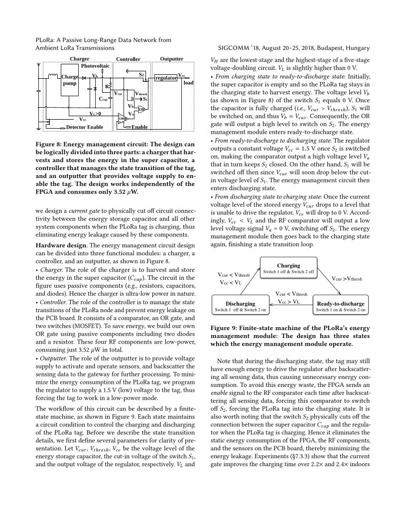
Figure 8: Energy management circuit: The design canbe logically divided into three parts: a charger that har-vests and stores the energy in the super capacitor, acontroller that manages the state transition of the tag,and an outputter that provides voltage supply to en-able the tag. The design works independently of theFPGA and consumes only 3.52 µW.
we design a current gate to physically cut off circuit connec-tivity between the energy storage capacitor and all othersystem components when the PLoRa tag is charging, thuseliminating energy leakage caused by these components.Hardware design. The energy management circuit designcan be divided into three functional modules: a charger, acontroller, and an outputter, as shown in Figure 8.• Charger. The role of the charger is to harvest and storethe energy in the super capacitor (Ccap ). The circuit in thefigure uses passive components (e.g., resistors, capacitors,and diodes). Hence the charger is ultra-low power in nature.• Controller. The role of the controller is to manage the statetransitions of the PLoRa node and prevent energy leakage onthe PCB board. It consists of a comparator, an OR gate, andtwo switches (MOSFET). To save energy, we build our ownOR gate using passive components including two diodesand a resistor. These four RF components are low-power,consuming just 3.52 µW in total.• Outputter. The role of the outputter is to provide voltagesupply to activate and operate sensors, and backscatter thesensing data to the gateway for further processing. To mini-mize the energy consumption of the PLoRa tag, we programthe regulator to supply a 1.5 V (low) voltage to the tag, thusforcing the tag to work in a low-power mode.The workflow of this circuit can be described by a finite-state machine, as shown in Figure 9. Each state maintainsa circuit condition to control the charging and dischargingof the PLoRa tag. Before we describe the state transitiondetails, we first define several parameters for clarity of pre-sentation. Let Vcur , Vthresh , Vcc be the voltage level of theenergy storage capacitor, the cut-in voltage of the switch S1,and the output voltage of the regulator, respectively. VL and
VH are the lowest-stage and the highest-stage of a five-stagevoltage-doubling circuit. VL is slightly higher than 0 V.• From charging state to ready-to-discharge state: Initially,the super capacitor is empty and so the PLoRa tag stays inthe charging state to harvest energy. The voltage level Vb(as shown in Figure 8) of the switch S1 equals 0 V. Oncethe capacitor is fully charged (i.e., Vcur > Vthresh ), S1 willbe switched on, and thus Vb = Vcur . Consequently, the ORgate will output a high level to switch on S2. The energymanagement module enters ready-to-discharge state.• From ready-to-discharge to discharging state: The regulatoroutputs a constant voltage Vcc = 1.5 V once S2 is switchedon, making the comparator output a high voltage level Vathat in turn keeps S2 closed. On the other hand, S1 will beswitched off then since Vcur will soon drop below the cut-in voltage level of S1. The energy management circuit thenenters discharging state.• From discharging state to charging state: Once the currentvoltage level of the stored energy Vcur drops to a level thatis unable to drive the regulator, Vcc will drop to 0 V. Accord-ingly, Vcc < VL and the RF comparator will output a lowlevel voltage signal Va = 0 V, switching off S2. The energymanagement module then goes back to the charging stateagain, finishing a state transition loop.
ChargingSwitch 1 off & Switch 2 off
Ready-to-dischargeSwitch 1 on & Switch 2 on
DischargingSwitch 1 off & Switch 2 on
Vcur >Vthresh
Vcur < Vthresh
Vcc > VL
Vcur < Vthresh
Vcc < VL
Figure 9: Finite-state machine of the PLoRa’s energymanagement module: The design has three stateswhich the energy management module operate.
Note that during the discharging state, the tag may stillhave enough energy to drive the regulator after backscatter-ing all sensing data, thus causing unnecessary energy con-sumption. To avoid this energy waste, the FPGA sends anenable signal to the RF comparator each time after backscat-tering all sensing data, forcing this comparator to switchoff S2, forcing the PLoRa tag into the charging state. It isalso worth noting that the switch S2 physically cuts off theconnection between the super capacitorCcap and the regula-tor when the PLoRa tag is charging. Hence it eliminates thestatic energy consumption of the FPGA, the RF components,and the sensors on the PCB board, thereby minimizing theenergy leakage. Experiments (§7.3.3) show that the currentgate improves the charging time over 2.2× and 2.4× indoors
SIGCOMM ’18, August 20–25, 2018, Budapest, Hungary Y. Peng et al.
and outdoors, respectively, compared to a design withoutthe current gate.
5 PLORA MAC LAYERSo far we have introduced the physical layer operation andthe energy management circuit design of the PLoRa tag. Inthis section, we describe MAC-layer operation. A typicalLoRaWAN consists of multiple active LoRa nodes that abideby the time-domain ALOHA protocol: all LoRa nodes workon the same channel but randomly pick up a time slot totransmit. Multiple PLoRa tags join a LoRaWAN to form ahybrid LoRaWAN network. These PLoRa tags abide by thefrequency-domain ALOHA protocol. Upon receiving an exci-tation, each PLoRa tag randomly shifts the backscatter signalto a different channel, which in turn reduces packet collisionrate and improves network scalability.
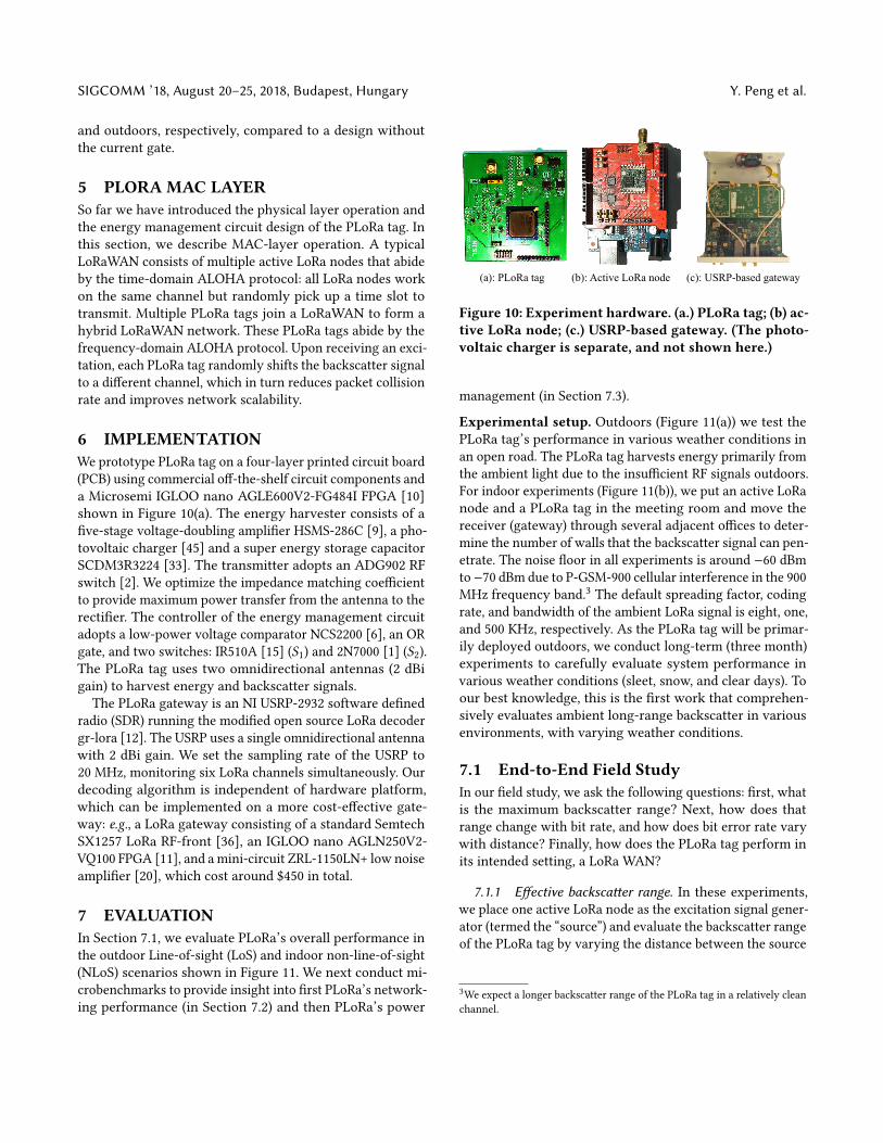
6 IMPLEMENTATIONWe prototype PLoRa tag on a four-layer printed circuit board(PCB) using commercial off-the-shelf circuit components anda Microsemi IGLOO nano AGLE600V2-FG484I FPGA [10]shown in Figure 10(a). The energy harvester consists of afive-stage voltage-doubling amplifier HSMS-286C [9], a pho-tovoltaic charger [45] and a super energy storage capacitorSCDM3R3224 [33]. The transmitter adopts an ADG902 RFswitch [2]. We optimize the impedance matching coefficientto provide maximum power transfer from the antenna to therectifier. The controller of the energy management circuitadopts a low-power voltage comparator NCS2200 [6], an ORgate, and two switches: IR510A [15] (S1) and 2N7000 [1] (S2).The PLoRa tag uses two omnidirectional antennas (2 dBigain) to harvest energy and backscatter signals.
The PLoRa gateway is an NI USRP-2932 software definedradio (SDR) running the modified open source LoRa decodergr-lora [12]. The USRP uses a single omnidirectional antennawith 2 dBi gain. We set the sampling rate of the USRP to20 MHz, monitoring six LoRa channels simultaneously. Ourdecoding algorithm is independent of hardware platform,which can be implemented on a more cost-effective gate-way: e.g., a LoRa gateway consisting of a standard SemtechSX1257 LoRa RF-front [36], an IGLOO nano AGLN250V2-VQ100 FPGA [11], and amini-circuit ZRL-1150LN+ low noiseamplifier [20], which cost around $450 in total.
7 EVALUATIONIn Section 7.1, we evaluate PLoRa’s overall performance inthe outdoor Line-of-sight (LoS) and indoor non-line-of-sight(NLoS) scenarios shown in Figure 11. We next conduct mi-crobenchmarks to provide insight into first PLoRa’s network-ing performance (in Section 7.2) and then PLoRa’s power
(a): PLoRa tag (b): Active LoRa node (c): USRP-based gateway
Figure 10: Experiment hardware. (a.) PLoRa tag; (b) ac-tive LoRa node; (c.) USRP-based gateway. (The photo-voltaic charger is separate, and not shown here.)
management (in Section 7.3).
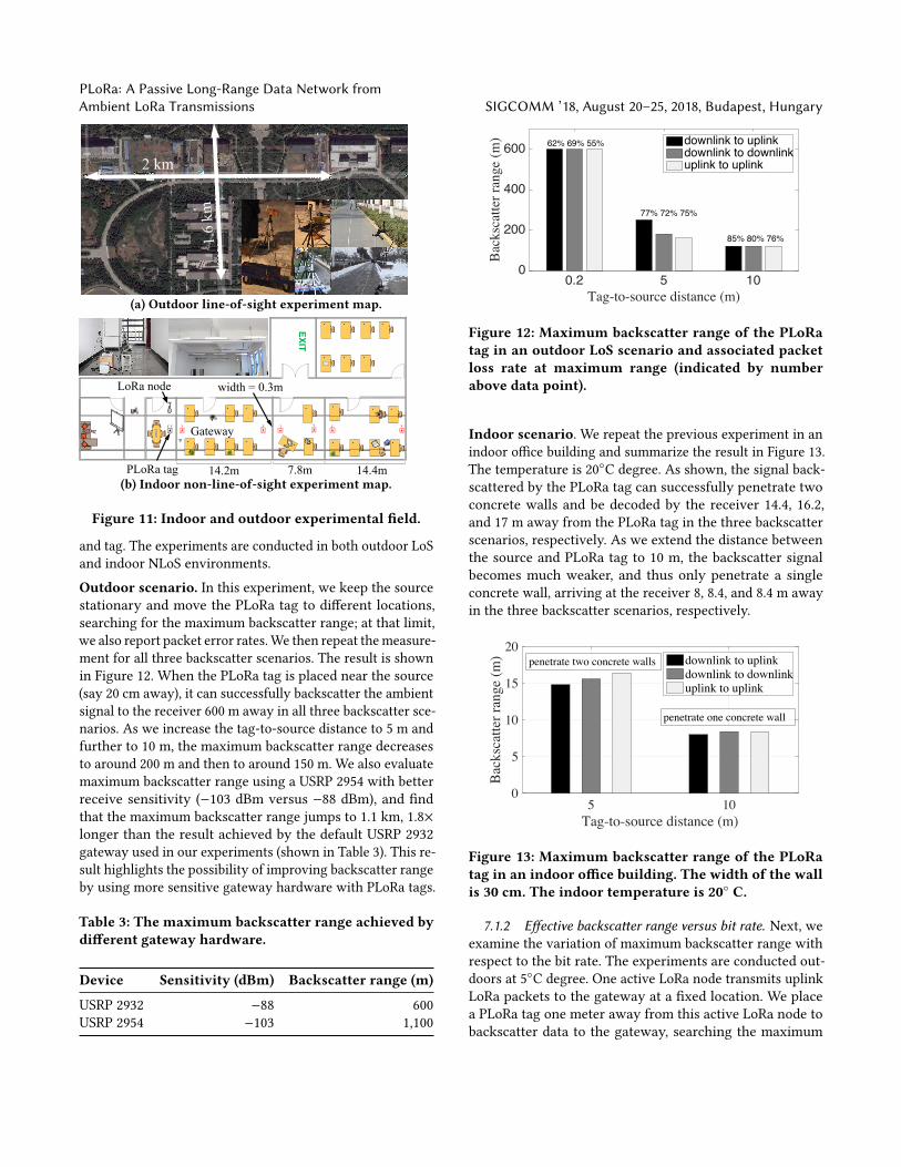
Experimental setup. Outdoors (Figure 11(a)) we test thePLoRa tag’s performance in various weather conditions inan open road. The PLoRa tag harvests energy primarily fromthe ambient light due to the insufficient RF signals outdoors.For indoor experiments (Figure 11(b)), we put an active LoRanode and a PLoRa tag in the meeting room and move thereceiver (gateway) through several adjacent offices to deter-mine the number of walls that the backscatter signal can pen-etrate. The noise floor in all experiments is around −60 dBmto−70 dBm due to P-GSM-900 cellular interference in the 900MHz frequency band.3 The default spreading factor, codingrate, and bandwidth of the ambient LoRa signal is eight, one,and 500 KHz, respectively. As the PLoRa tag will be primar-ily deployed outdoors, we conduct long-term (three month)experiments to carefully evaluate system performance invarious weather conditions (sleet, snow, and clear days). Toour best knowledge, this is the first work that comprehen-sively evaluates ambient long-range backscatter in variousenvironments, with varying weather conditions.
7.1 End-to-End Field StudyIn our field study, we ask the following questions: first, whatis the maximum backscatter range? Next, how does thatrange change with bit rate, and how does bit error rate varywith distance? Finally, how does the PLoRa tag perform inits intended setting, a LoRa WAN?
7.1.1 Effective backscatter range. In these experiments,we place one active LoRa node as the excitation signal gener-ator (termed the “source”) and evaluate the backscatter rangeof the PLoRa tag by varying the distance between the source
3We expect a longer backscatter range of the PLoRa tag in a relatively cleanchannel.
PLoRa: A Passive Long-Range Data Network fromAmbient LoRa Transmissions SIGCOMM ’18, August 20–25, 2018, Budapest, Hungary
2 km
1.6
km
(a) Outdoor line-of-sight experiment map.
EXIT
Gateway
PLoRa tag 14.2m
width = 0.3m
7.8m 14.4m
LoRa node
(b) Indoor non-line-of-sight experiment map.
Figure 11: Indoor and outdoor experimental field.
and tag. The experiments are conducted in both outdoor LoSand indoor NLoS environments.
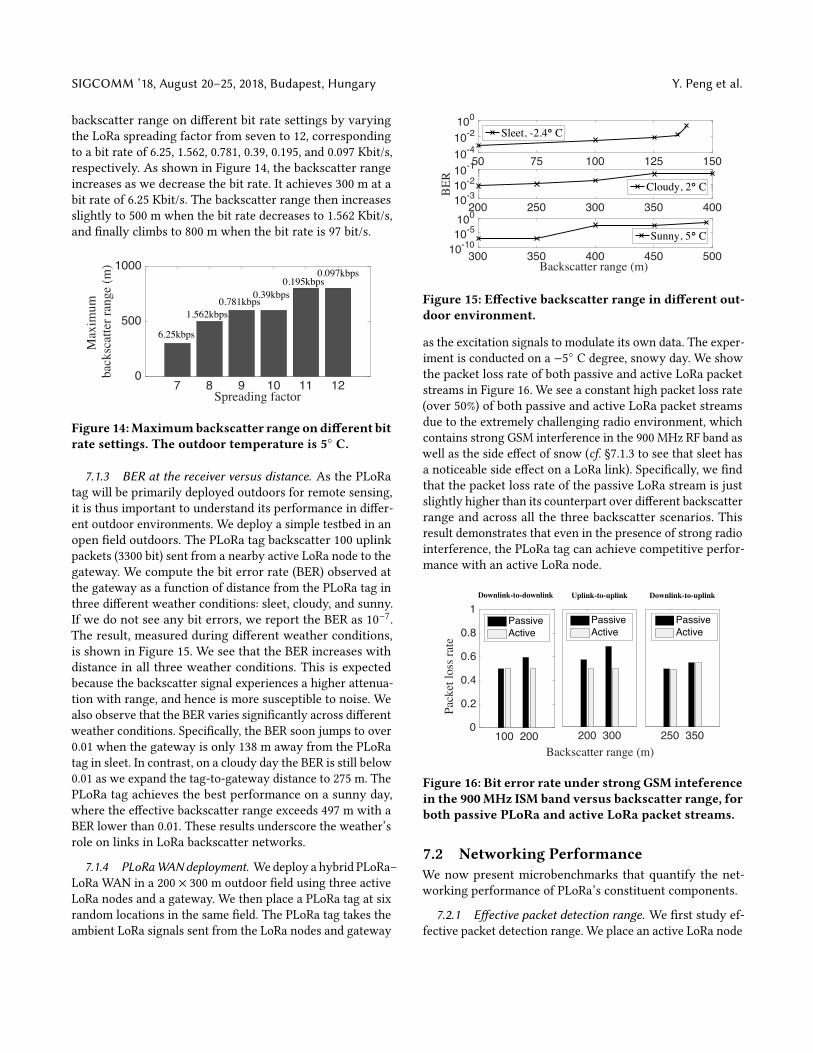
Outdoor scenario. In this experiment, we keep the sourcestationary and move the PLoRa tag to different locations,searching for the maximum backscatter range; at that limit,we also report packet error rates.We then repeat themeasure-ment for all three backscatter scenarios. The result is shownin Figure 12. When the PLoRa tag is placed near the source(say 20 cm away), it can successfully backscatter the ambientsignal to the receiver 600 m away in all three backscatter sce-narios. As we increase the tag-to-source distance to 5 m andfurther to 10 m, the maximum backscatter range decreasesto around 200 m and then to around 150 m. We also evaluatemaximum backscatter range using a USRP 2954 with betterreceive sensitivity (−103 dBm versus −88 dBm), and findthat the maximum backscatter range jumps to 1.1 km, 1.8×longer than the result achieved by the default USRP 2932gateway used in our experiments (shown in Table 3). This re-sult highlights the possibility of improving backscatter rangeby using more sensitive gateway hardware with PLoRa tags.
Table 3: The maximum backscatter range achieved bydifferent gateway hardware.
Device Sensitivity (dBm) Backscatter range (m)
USRP 2932 −88 600USRP 2954 −103 1,100
0.2 5 10Tag-to-source distance (m)
0
200
400
600
Back
scat
ter r
ange
(m) downlink to uplink
downlink to downlinkuplink to uplink
62% 69% 55%
77% 72% 75%
85% 80% 76%
Figure 12: Maximum backscatter range of the PLoRatag in an outdoor LoS scenario and associated packetloss rate at maximum range (indicated by numberabove data point).
Indoor scenario. We repeat the previous experiment in anindoor office building and summarize the result in Figure 13.The temperature is 20◦C degree. As shown, the signal back-scattered by the PLoRa tag can successfully penetrate twoconcrete walls and be decoded by the receiver 14.4, 16.2,and 17 m away from the PLoRa tag in the three backscatterscenarios, respectively. As we extend the distance betweenthe source and PLoRa tag to 10 m, the backscatter signalbecomes much weaker, and thus only penetrate a singleconcrete wall, arriving at the receiver 8, 8.4, and 8.4 m awayin the three backscatter scenarios, respectively.
5 10Tag-to-source distance (m)
0
5
10
15
20
Back
scat
ter r
ange
(m) downlink to uplink
downlink to downlinkuplink to uplink
penetrate two concrete walls
penetrate one concrete wall
Figure 13: Maximum backscatter range of the PLoRatag in an indoor office building. The width of the wallis 30 cm. The indoor temperature is 20◦ C.
7.1.2 Effective backscatter range versus bit rate. Next, weexamine the variation of maximum backscatter range withrespect to the bit rate. The experiments are conducted out-doors at 5◦C degree. One active LoRa node transmits uplinkLoRa packets to the gateway at a fixed location. We placea PLoRa tag one meter away from this active LoRa node tobackscatter data to the gateway, searching the maximum
SIGCOMM ’18, August 20–25, 2018, Budapest, Hungary Y. Peng et al.
backscatter range on different bit rate settings by varyingthe LoRa spreading factor from seven to 12, correspondingto a bit rate of 6.25, 1.562, 0.781, 0.39, 0.195, and 0.097 Kbit/s,respectively. As shown in Figure 14, the backscatter rangeincreases as we decrease the bit rate. It achieves 300 m at abit rate of 6.25 Kbit/s. The backscatter range then increasesslightly to 500 m when the bit rate decreases to 1.562 Kbit/s,and finally climbs to 800 m when the bit rate is 97 bit/s.
7 8 9 10 11 12Spreading factor
0
500
1000
Max
imum
ba
cksc
atte
r ran
ge (m
)
1.562kbps0.781kbps
6.25kbps
0.39kbps0.195kbps
0.097kbps
Figure 14:Maximumbackscatter range ondifferent bitrate settings. The outdoor temperature is 5◦ C.
7.1.3 BER at the receiver versus distance. As the PLoRatag will be primarily deployed outdoors for remote sensing,it is thus important to understand its performance in differ-ent outdoor environments. We deploy a simple testbed in anopen field outdoors. The PLoRa tag backscatter 100 uplinkpackets (3300 bit) sent from a nearby active LoRa node to thegateway. We compute the bit error rate (BER) observed atthe gateway as a function of distance from the PLoRa tag inthree different weather conditions: sleet, cloudy, and sunny.If we do not see any bit errors, we report the BER as 10−7.The result, measured during different weather conditions,is shown in Figure 15. We see that the BER increases withdistance in all three weather conditions. This is expectedbecause the backscatter signal experiences a higher attenua-tion with range, and hence is more susceptible to noise. Wealso observe that the BER varies significantly across differentweather conditions. Specifically, the BER soon jumps to over0.01 when the gateway is only 138 m away from the PLoRatag in sleet. In contrast, on a cloudy day the BER is still below0.01 as we expand the tag-to-gateway distance to 275 m. ThePLoRa tag achieves the best performance on a sunny day,where the effective backscatter range exceeds 497 m with aBER lower than 0.01. These results underscore the weather’srole on links in LoRa backscatter networks.
7.1.4 PLoRaWANdeployment. Wedeploy a hybrid PLoRa–LoRa WAN in a 200 × 300 m outdoor field using three activeLoRa nodes and a gateway. We then place a PLoRa tag at sixrandom locations in the same field. The PLoRa tag takes theambient LoRa signals sent from the LoRa nodes and gateway
50 75 100 125 15010-410-2100
Sleet, -2.4° C
200 250 300 350 40010-310-210-1
BER
Cloudy, 2° C
300 350 400 450 500Backscatter range (m)
10-1010-5100
Sunny, 5° C
Figure 15: Effective backscatter range in different out-door environment.
as the excitation signals to modulate its own data. The exper-iment is conducted on a −5◦ C degree, snowy day. We showthe packet loss rate of both passive and active LoRa packetstreams in Figure 16. We see a constant high packet loss rate(over 50%) of both passive and active LoRa packet streamsdue to the extremely challenging radio environment, whichcontains strong GSM interference in the 900 MHz RF band aswell as the side effect of snow (cf. §7.1.3 to see that sleet hasa noticeable side effect on a LoRa link). Specifically, we findthat the packet loss rate of the passive LoRa stream is justslightly higher than its counterpart over different backscatterrange and across all the three backscatter scenarios. Thisresult demonstrates that even in the presence of strong radiointerference, the PLoRa tag can achieve competitive perfor-mance with an active LoRa node.
100 2000
0.2
0.4
0.6
0.8
1
Pack
et lo
ss ra
te
Downlink-to-downlink
PassiveActive
200 300Backscatter range (m)
Uplink-to-uplink
PassiveActive
250 350
Downlink-to-uplink
PassiveActive
Figure 16: Bit error rate under strong GSM inteferencein the 900MHz ISM band versus backscatter range, forboth passive PLoRa and active LoRa packet streams.
7.2 Networking PerformanceWe now present microbenchmarks that quantify the net-working performance of PLoRa’s constituent components.
7.2.1 Effective packet detection range. We first study ef-fective packet detection range. We place an active LoRa node
PLoRa: A Passive Long-Range Data Network fromAmbient LoRa Transmissions SIGCOMM ’18, August 20–25, 2018, Budapest, Hungary
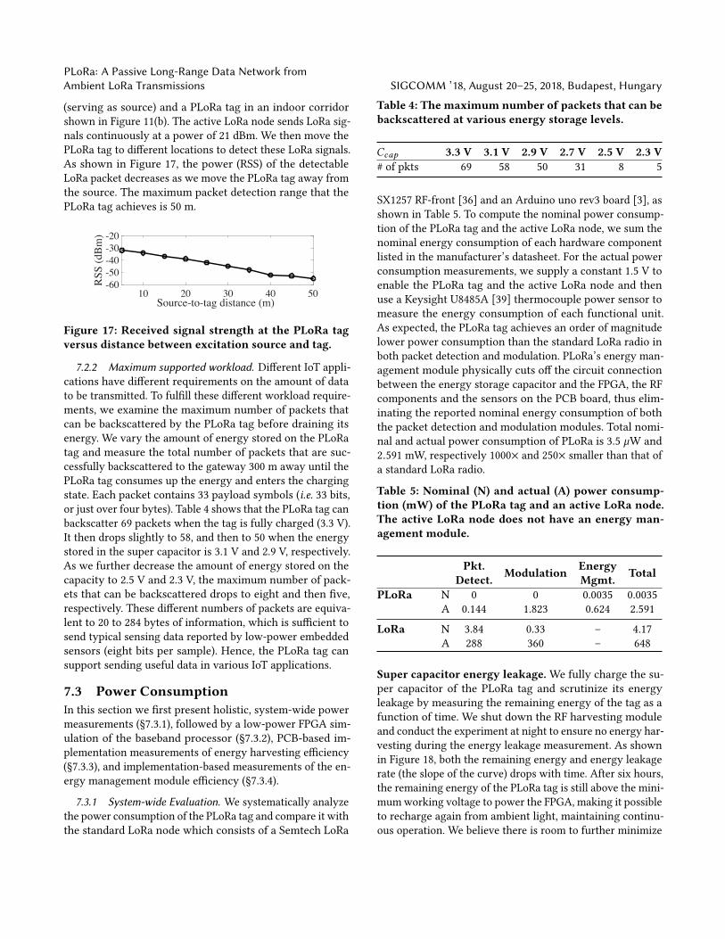
(serving as source) and a PLoRa tag in an indoor corridorshown in Figure 11(b). The active LoRa node sends LoRa sig-nals continuously at a power of 21 dBm. We then move thePLoRa tag to different locations to detect these LoRa signals.As shown in Figure 17, the power (RSS) of the detectableLoRa packet decreases as we move the PLoRa tag away fromthe source. The maximum packet detection range that thePLoRa tag achieves is 50 m.
10 20 30 40 50Source-to-tag distance (m)
-60-50-40-30-20
RSS
(dBm
)
Figure 17: Received signal strength at the PLoRa tagversus distance between excitation source and tag.
7.2.2 Maximum supported workload. Different IoT appli-cations have different requirements on the amount of datato be transmitted. To fulfill these different workload require-ments, we examine the maximum number of packets thatcan be backscattered by the PLoRa tag before draining itsenergy. We vary the amount of energy stored on the PLoRatag and measure the total number of packets that are suc-cessfully backscattered to the gateway 300 m away until thePLoRa tag consumes up the energy and enters the chargingstate. Each packet contains 33 payload symbols (i.e. 33 bits,or just over four bytes). Table 4 shows that the PLoRa tag canbackscatter 69 packets when the tag is fully charged (3.3 V).It then drops slightly to 58, and then to 50 when the energystored in the super capacitor is 3.1 V and 2.9 V, respectively.As we further decrease the amount of energy stored on thecapacity to 2.5 V and 2.3 V, the maximum number of pack-ets that can be backscattered drops to eight and then five,respectively. These different numbers of packets are equiva-lent to 20 to 284 bytes of information, which is sufficient tosend typical sensing data reported by low-power embeddedsensors (eight bits per sample). Hence, the PLoRa tag cansupport sending useful data in various IoT applications.
7.3 Power ConsumptionIn this section we first present holistic, system-wide powermeasurements (§7.3.1), followed by a low-power FPGA sim-ulation of the baseband processor (§7.3.2), PCB-based im-plementation measurements of energy harvesting efficiency(§7.3.3), and implementation-based measurements of the en-ergy management module efficiency (§7.3.4).
7.3.1 System-wide Evaluation. We systematically analyzethe power consumption of the PLoRa tag and compare it withthe standard LoRa node which consists of a Semtech LoRa
Table 4: The maximum number of packets that can bebackscattered at various energy storage levels.
Ccap 3.3 V 3.1 V 2.9 V 2.7 V 2.5 V 2.3 V# of pkts 69 58 50 31 8 5
SX1257 RF-front [36] and an Arduino uno rev3 board [3], asshown in Table 5. To compute the nominal power consump-tion of the PLoRa tag and the active LoRa node, we sum thenominal energy consumption of each hardware componentlisted in the manufacturer’s datasheet. For the actual powerconsumption measurements, we supply a constant 1.5 V toenable the PLoRa tag and the active LoRa node and thenuse a Keysight U8485A [39] thermocouple power sensor tomeasure the energy consumption of each functional unit.As expected, the PLoRa tag achieves an order of magnitudelower power consumption than the standard LoRa radio inboth packet detection and modulation. PLoRa’s energy man-agement module physically cuts off the circuit connectionbetween the energy storage capacitor and the FPGA, the RFcomponents and the sensors on the PCB board, thus elim-inating the reported nominal energy consumption of boththe packet detection and modulation modules. Total nomi-nal and actual power consumption of PLoRa is 3.5 µW and2.591 mW, respectively 1000× and 250× smaller than that ofa standard LoRa radio.
Table 5: Nominal (N) and actual (A) power consump-tion (mW) of the PLoRa tag and an active LoRa node.The active LoRa node does not have an energy man-agement module.
Pkt.Detect. Modulation Energy
Mgmt. Total
PLoRa N 0 0 0.0035 0.0035A 0.144 1.823 0.624 2.591
LoRa N 3.84 0.33 – 4.17A 288 360 – 648
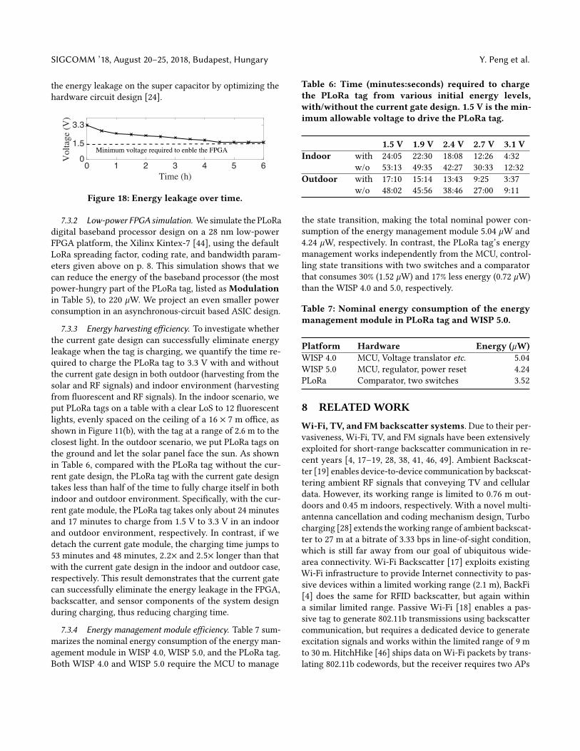
Super capacitor energy leakage. We fully charge the su-per capacitor of the PLoRa tag and scrutinize its energyleakage by measuring the remaining energy of the tag as afunction of time. We shut down the RF harvesting moduleand conduct the experiment at night to ensure no energy har-vesting during the energy leakage measurement. As shownin Figure 18, both the remaining energy and energy leakagerate (the slope of the curve) drops with time. After six hours,the remaining energy of the PLoRa tag is still above the mini-mumworking voltage to power the FPGA, making it possibleto recharge again from ambient light, maintaining continu-ous operation. We believe there is room to further minimize
SIGCOMM ’18, August 20–25, 2018, Budapest, Hungary Y. Peng et al.
the energy leakage on the super capacitor by optimizing thehardware circuit design [24].
0 1 2 3 4 5 6Time (h)
0
1.5
3.3
Vol
tage
(V)
Minimum voltage required to enble the FPGA
Figure 18: Energy leakage over time.
7.3.2 Low-power FPGA simulation. We simulate the PLoRadigital baseband processor design on a 28 nm low-powerFPGA platform, the Xilinx Kintex-7 [44], using the defaultLoRa spreading factor, coding rate, and bandwidth param-eters given above on p. 8. This simulation shows that wecan reduce the energy of the baseband processor (the mostpower-hungry part of the PLoRa tag, listed as Modulationin Table 5), to 220 µW. We project an even smaller powerconsumption in an asynchronous-circuit based ASIC design.
7.3.3 Energy harvesting efficiency. To investigate whetherthe current gate design can successfully eliminate energyleakage when the tag is charging, we quantify the time re-quired to charge the PLoRa tag to 3.3 V with and withoutthe current gate design in both outdoor (harvesting from thesolar and RF signals) and indoor environment (harvestingfrom fluorescent and RF signals). In the indoor scenario, weput PLoRa tags on a table with a clear LoS to 12 fluorescentlights, evenly spaced on the ceiling of a 16 × 7 m office, asshown in Figure 11(b), with the tag at a range of 2.6 m to theclosest light. In the outdoor scenario, we put PLoRa tags onthe ground and let the solar panel face the sun. As shownin Table 6, compared with the PLoRa tag without the cur-rent gate design, the PLoRa tag with the current gate designtakes less than half of the time to fully charge itself in bothindoor and outdoor environment. Specifically, with the cur-rent gate module, the PLoRa tag takes only about 24 minutesand 17 minutes to charge from 1.5 V to 3.3 V in an indoorand outdoor environment, respectively. In contrast, if wedetach the current gate module, the charging time jumps to53 minutes and 48 minutes, 2.2× and 2.5× longer than thatwith the current gate design in the indoor and outdoor case,respectively. This result demonstrates that the current gatecan successfully eliminate the energy leakage in the FPGA,backscatter, and sensor components of the system designduring charging, thus reducing charging time.
7.3.4 Energy management module efficiency. Table 7 sum-marizes the nominal energy consumption of the energy man-agement module in WISP 4.0, WISP 5.0, and the PLoRa tag.Both WISP 4.0 and WISP 5.0 require the MCU to manage
Table 6: Time (minutes:seconds) required to chargethe PLoRa tag from various initial energy levels,with/without the current gate design. 1.5 V is the min-imum allowable voltage to drive the PLoRa tag.
1.5 V 1.9 V 2.4 V 2.7 V 3.1 VIndoor with 24:05 22:30 18:08 12:26 4:32
w/o 53:13 49:35 42:27 30:33 12:32Outdoor with 17:10 15:14 13:43 9:25 3:37
w/o 48:02 45:56 38:46 27:00 9:11
the state transition, making the total nominal power con-sumption of the energy management module 5.04 µW and4.24 µW, respectively. In contrast, the PLoRa tag’s energymanagement works independently from the MCU, control-ling state transitions with two switches and a comparatorthat consumes 30% (1.52 µW) and 17% less energy (0.72 µW)than the WISP 4.0 and 5.0, respectively.
Table 7: Nominal energy consumption of the energymanagement module in PLoRa tag and WISP 5.0.
Platform Hardware Energy (µW)WISP 4.0 MCU, Voltage translator etc. 5.04WISP 5.0 MCU, regulator, power reset 4.24PLoRa Comparator, two switches 3.52
8 RELATEDWORK
Wi-Fi, TV, and FM backscatter systems. Due to their per-vasiveness, Wi-Fi, TV, and FM signals have been extensivelyexploited for short-range backscatter communication in re-cent years [4, 17–19, 28, 38, 41, 46, 49]. Ambient Backscat-ter [19] enables device-to-device communication by backscat-tering ambient RF signals that conveying TV and cellulardata. However, its working range is limited to 0.76 m out-doors and 0.45 m indoors, respectively. With a novel multi-antenna cancellation and coding mechanism design, Turbocharging [28] extends theworking range of ambient backscat-ter to 27 m at a bitrate of 3.33 bps in line-of-sight condition,which is still far away from our goal of ubiquitous wide-area connectivity. Wi-Fi Backscatter [17] exploits existingWi-Fi infrastructure to provide Internet connectivity to pas-sive devices within a limited working range (2.1 m), BackFi[4] does the same for RFID backscatter, but again withina similar limited range. Passive Wi-Fi [18] enables a pas-sive tag to generate 802.11b transmissions using backscattercommunication, but requires a dedicated device to generateexcitation signals and works within the limited range of 9 mto 30 m. HitchHike [46] ships data on Wi-Fi packets by trans-lating 802.11b codewords, but the receiver requires two APs
PLoRa: A Passive Long-Range Data Network fromAmbient LoRa Transmissions SIGCOMM ’18, August 20–25, 2018, Budapest, Hungary
to collaboratively decode the information, which limits itsdeployment. FS-backscatter [49] designs a low-power ringoscillator (20 µW) to shift Wi-Fi signals to a different chan-nel up to 20 MHz away for collision avoidance. In contrast,PLoRa shifts the signal for both chirp modulation and colli-sion avoidance. FM Backscatter [41] uses ambient FM signalsas a source and creates decodable backscatter transmissionson any FM receiver: while an ambient backscatter design, itsworking range is 1.5–10 m.
Low-power wireless systems. The communication link isamong the most power-hungry parts of a typical IoT plat-form, and various low-power wireless systems have beenproposed in the past. Picoradio [30] has pioneered this field,introducing a µW radio design that harvests energy from thesolar and transmit data at several bit per second. Bluetoothlow energy (BLE) [5] works in the 2.4 GHz band and is widelyused in wearable devices, mobiles, and smart home devices.Zigbee [51] is a low-power wireless technology based onIEEE 802.15.4 and designed for local area networks with low-power radios such as wireless sensornets. Both Zigbee andBLE signals are interfered by Wi-Fi transmissions, especiallyin urban areas where APs are densely deployed. Interscatter[16] backscatters Wi-Fi signals from a Bluetooth excitationsignal, but works overWi-Fi ranges (80 ft.) or less. Sigfox [34]works in the UHF band and transmits PSK modulated data atvery low data rate, thus achieving long range like LoRa. Nar-rowBand IoT (NB-IoT) [25] is designed for connecting a widerange of static IoT devices using cellular telecommunicationsbands. Among the low-power wireless communication tech-nologies, LoRa is most resilient to both in- and out-of-bandinterference [37], making it a natural choice for backscatter.LoRa Backscatter [38], introduces a chirp spread spectrum(CSS) backscatter design and harmonic cancellation mecha-nism to generate a standard LoRa packet that can be decodedby standard LoRa gateway 2 km away. However, it requiresa dedicated device to generate a sinusoidal tone as the ex-citation signal, thus making it less practical for open-fielddeployment. In contrast, PLoRa does not require a dedicatedexcitation signal generator, instead exploiting ambient LoRatransmissions. Other work has nearby LoRa nodes transmita continuous wave excitation signal [29], but again at theexpense of their own energy reserves and wireless spectralresources.
Energy management. The energy management modulesonmany backscatter systems (e.g.,WISP [43], Ambient Backscat-ter [19], Wi-Fi backscatter [17] etc.) handle state transitionsbut don’t ensure data integrity. Furthermore, these systemsenter the charging state after energy depletion, but still keepthe circuit connection between the energy storage capacitorand the regulator, causing substantial energy leakage. Tomaintain data integrity, Mementos [31] adopts a checkpoint
design to save program instructions or data to nonvolatilememory when energy is about to run out. However, Me-mentos needs to frequently sample the voltage level of thecapacitor, which increases the CPU workload and thus is notenergy-efficient. QuarkNet [47] segments a data frame intosmaller micro-frames with various sizes depending on theprevailing energy harvesting conditions, thus ensuring thedata integrity of each transmitted frame. PLoRa, on the otherhand, adopts a hardware-based solution using a super-ca-pacitor coupled with highly efficient energy managementhardware, to achieve the same end.
9 DISCUSSION
Improving packet detection range. The maximum packetdetection range of the PLoRa tag is 50 m. This range canbe further improved by leveraging the advanced envelopedetector design [27, 32]. For example, the state-of-the-artenvelope detector achieves -71 dBm sensitivity [13], trans-lating to 565 m effective packet detection range based on anopen-field experiment. We leave this as future work.
Out-of-band LoRa signal interference. The tag’s enve-lope detector essentially captures energy from all LoRa chan-nels and hence is unable to detect incoming excitation whenmultiple LoRa nodes transmit on different channels at thesame time. However, this rarely happens in practice sincemany LoRa nodes typically transmit on the same channel ina typical LoRaWAN network [8].
Large-scale deployment. Our current evaluation resultsare based on a small testbed with one PLoRa tag and threeactive LoRa nodes. As more PLoRa tags join the network,packet collision rate will inherently increase. Our futureplan is to deploy a larger hybrid LoRa testbed outdoors withtens of active LoRa nodes and PLoRa tags, examining therobustness of PLoRa’s design.
10 CONCLUSIONPLoRa is an ambient, passive LoRa backscatter design thatprovides low-power and long-range connectivity for IoT de-vices. Our design combines a low-power packet detectioncircuit with novel blind chirp modulation and harmonic can-cellation techniques. Our PCB prototype can backscatter toa LoRa gateway up to 1.1 km away and deliver 284 bytes ofsensor data with a 17 minute duty cycle.
ACKNOWLEDGEMENTSWe thank our shepherd Prof. Fadel Adib and the anonymousreviewers for their constructive feedback. This work is sup-ported by NSF Awards #1617161 and #1763309, NSFC Awards#61772422 and #61672428.
SIGCOMM ’18, August 20–25, 2018, Budapest, Hungary Y. Peng et al.
REFERENCES[1] 2N7000 MOSFET. Website.[2] ADG902 RF switch. Website.[3] Arduino uno rev3. Website.[4] D. Bharadia, K. R. Joshi, M. Kotaru, S. Katti. BackFi: High throughput
Wi-Fi backscatter. SIGCOMM Comput. Commun. Rev., 45(4), 283–296,2015.
[5] Bluetooth low energy. Website.[6] NCS2200 Series, NCS2200A Low Voltage Comparators. Website.[7] D. M. Dobkin. The RF in RFID: UHF RFID in practice. Newnes, 2012.[8] A. Dongare, R. Narayanan, A. Gadre, A. Luong, A. Balanuta, S. Kumar,
B. Iannucci, A. Rowe. Charm: Exploiting geographical diversitythrough coherent combining in low-power wide-area networks. IPSN,2018.
[9] Surface Mount Microwave Schottky Detector Diodes. Website.[10] IGLOO nano FPGAs. Website.[11] Microsemi Corporation AGLN250V2-VQ100 FPGA. .[12] gr-lora decoder. Website.[13] C. Hambeck, S. Mahlknecht, T. Herndl. A 2.4 µw wake-up receiver for
wireless sensor nodes with- 71dbm sensitivity. Circuits and Systems(ISCAS), 2011 IEEE International Symposium on, 2011.
[14] P. Hu, P. Zhang, D. Ganesan. Laissez-faire: Fully asymmetricbackscatter communication. SIGCOMM, 2015.
[15] IR510A MOSFET. Website.[16] V. Iyer, V. Talla, B. Kellogg, S. Gollakota, J. Smith. Inter-technology
backscatter: Towards internet connectivity for implanted devices.SIGCOMM, 2016.
[17] B. Kellogg, A. Parks, S. Gollakota, J. R. Smith, D. Wetherall. Wi-Fibackscatter: Internet connectivity for RF-powered devices. SIGCOMM,2014.
[18] B. Kellogg, V. Talla, S. Gollakota, J. R. Smith. Passive Wi-Fi: BringingLow Power to Wi-Fi Transmissions. NSDI, 2016.
[19] V. Liu, A. Parks, V. Talla, S. Gollakota, D. Wetherall, J. R. Smith.Ambient backscatter: wireless communication out of thin air.SIGCOMM, 2013.
[20] Mini-circuit ZRL-1150LN+ low noise amplifier. .[21] LoRa. Website.[22] Four-faith LoRa application. Website.[23] C. Lu, V. Raghunathan, K. Roy. Efficient design of micro-scale energy
harvesting systems. IEEE Journal on Emerging and Selected Topics inCircuits and Systems, 2011.
[24] S. Naderiparizi, A. N. Parks, Z. Kapetanovic, B. Ransford, J. R. Smith.Wispcam: A battery-free rfid camera. RFID, 2015.
[25] Narrow-band IoT. Website.[26] P. Nintanavongsa, U. Muncuk, D. R. Lewis, K. R. Chowdhury. Design
optimization and implementation for RF energy harvesting circuits.IEEE Journal on emerging and selected topics in circuits and systems,2012.
[27] S. Oh, N. E. Roberts, D. D. Wentzloff. A 116nw multi-band wake-upreceiver with 31-bit correlator and interference rejection. CICC, 2013IEEE, 2013.
[28] A. N. Parks, A. Liu, S. Gollakota, J. R. Smith. Turbocharging ambientbackscatter communication. SIGCOMM, 2015.
[29] C. Pérez-Penichet, F. Hermans, A. Varshney, T. Voight. AugmentingIoT networks with backscatter-enabled passive sensor tags.HotWireless, 2016.
[30] J. M. Rabaey, M. J. Ammer, J. L. da Silva, D. Patel, S. Roundy. Picoradiosupports ad hoc ultra-low power wireless networking. Computer,33(7), 42–48, 2000.
[31] B. Ransford, J. Sorber, K. Fu. Mementos: System support forlong-running computation on RFID-scale devices. ACM SIGPLAN
Notices, 2012.[32] N. E. Roberts, D. D. Wentzloff. Ultra-low power wake-up radios.
Ultra-Low-Power Short-Range Radios, 137–162, 2015.[33] Samwha Tech Corp. SCDM3R3224 super capacitor. Website.[34] Sigfox. Website.[35] LoRa Technology Is Connecting Our Smart Planet. Website.[36] Semtech SX1257. Website.[37] Semtech SX1276 Transceiver. Website.[38] V. Talla, M. Hessar, B. Kellogg, A. Najafi, J. R. Smith, S. Gollakota.
LoRa Backscatter: Enabling The Vision of Ubiquitous Connectivity.IMWUT, 2017.
[39] U8485A DC/10 MHz–33 GHz USB Thermocouple Power Sensor.Website.
[40] A. Varshney, O. Harms, C. Pérez-Penichet, C. Rohner, F. Hermans,T. Voigt. Lorea: A backsca er architecture that achieves a longcommunication range. SenSys, 2017.
[41] A. Wang, V. Iyer, V. Talla, J. R. Smith, S. Gollakota. FM Backscatter:Enabling Connected Cities and Smart Fabrics. NSDI, 2017.
[42] J. Wang, H. Hassanieh, D. Katabi, P. Indyk. Efficient and reliablelow-power backscatter networks. SIGCOMM, 2012.
[43] Intel WISP 4.0. Website.[44] Xilinx kintex 7 datasheet. Website.[45] Photovoltaic Charger XRYG-905. Website.[46] P. Zhang, D. Bharadia, K. R. Joshi, S. Katti. HitchHike: Practical
Backscatter Using Commodity WiFi. SenSys, 2016.[47] P. Zhang, D. Ganesan. Enabling bit-by-bit backscatter communication
in severe energy harvesting environments. NSDI, 2014.[48] P. Zhang, C. Josephson, D. Bharadia, S. Katti. Freerider: Backscatter
communication using commodity radios. CoNEXT, 2017.[49] P. Zhang, M. Rostami, P. Hu, D. Ganesan. Enabling practical
backscatter communication for on-body sensors. SIGCOMM, 2016.[50] X. Zhang, K. G. Shin. E-mili: Energy-minimizing idle listening in
wireless networks. IEEE Transactions on Mobile Computing, 2012.[51] Zigbee. Website.


![Reliable Wide-Area Backscatter via Channel Polarizationments using PLoRa backscatter [8] in LoS and NLoS scenarios, as shown in Fig. 10. For each experiment, we let an active LoRa](https://img.pdfslide.us/doc/110x75/5f9d4c5be8785552cf052162/reliable-wide-area-backscatter-via-channel-polarization-ments-using-plora-backscatter.jpg)