Embed Size (px)
Citation preview
PLM Smart Plug Solutions
Filippo Colaianni
Technical Marketing Section ManagerSmart Grid & Connectivity
IMS Systems Lab & Technical Marketing
Agenda
• The Smart Plug Concept
• The PLM smart plug demo board
• Hardware:• PLM section• Metering Section
• Firmware:• Architecture• Communication protocol
• Conclusions
2
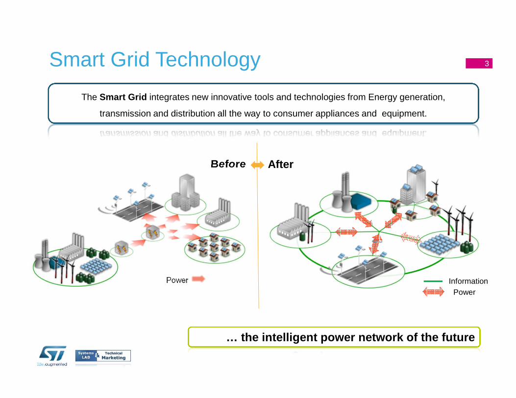
Smart Grid Technology
The Smart Grid integrates new innovative tools and technologies from Energy generation,
transmission and distribution all the way to consumer appliances and equipment.
Before After
InformationPower
Power
… the intelligent power network of the future
3
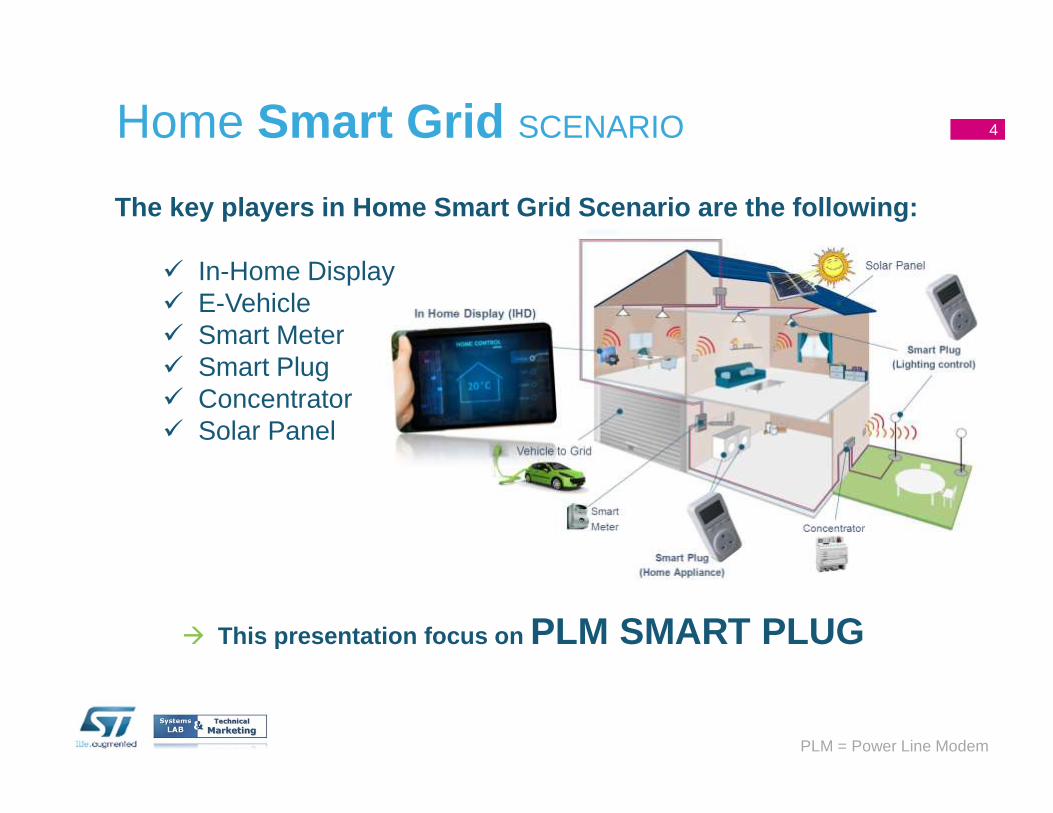
Home Smart Grid SCENARIO
� This presentation focus on PLM SMART PLUG
PLM = Power Line Modem
4
The key players in Home Smart Grid Scenario are the following:
� In-Home Display� E-Vehicle� Smart Meter� Smart Plug � Concentrator� Solar Panel
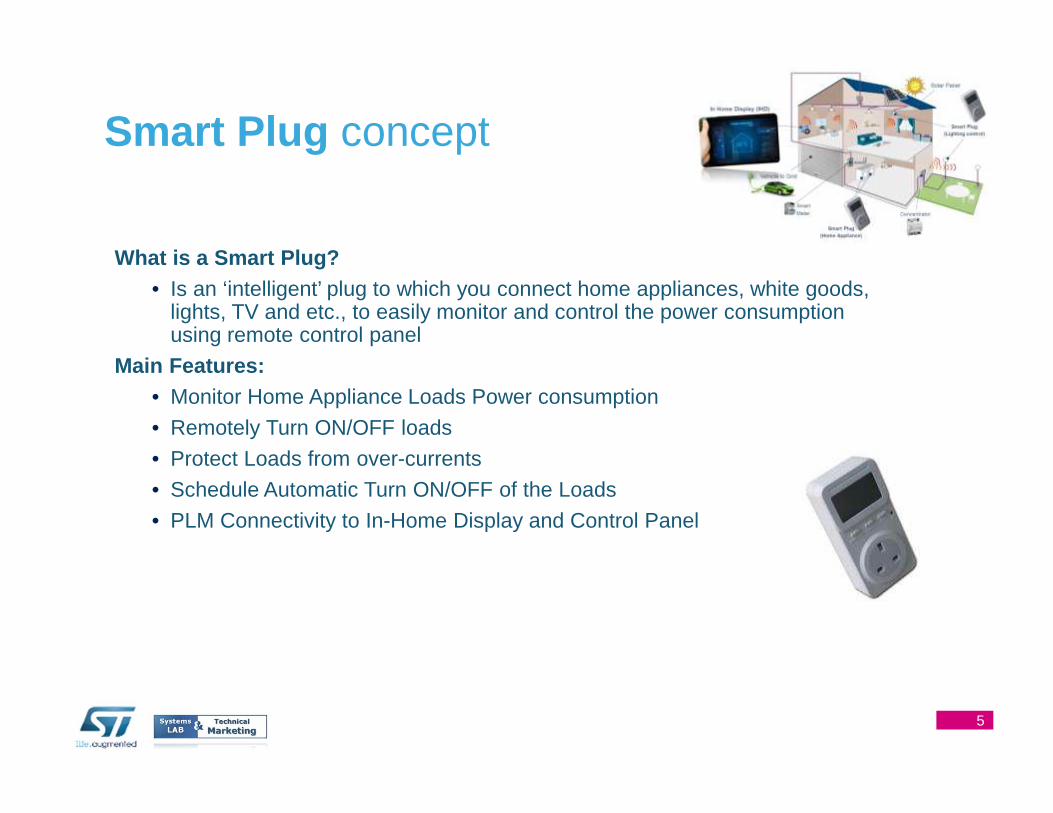
What is a Smart Plug ?• Is an ‘intelligent’ plug to which you connect home appliances, white goods,
lights, TV and etc., to easily monitor and control the power consumption using remote control panel
Main Features:• Monitor Home Appliance Loads Power consumption
• Remotely Turn ON/OFF loads
• Protect Loads from over-currents
• Schedule Automatic Turn ON/OFF of the Loads
• PLM Connectivity to In-Home Display and Control Panel
Smart Plug concept
5
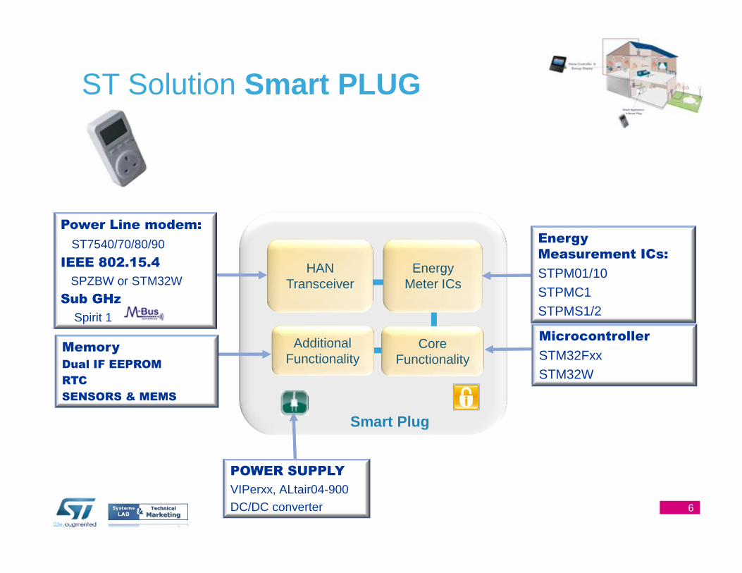
HAN Transceiver
Energy Meter ICs
Smart Plug
Core Functionality
Energy
Measurement ICs:
STPM01/10STPMC1STPMS1/2
Power Line modem:
ST7540/70/80/90
IEEE 802.15.4
SPZBW or STM32W
Sub GHz
Spirit 1
POWER SUPPLY
VIPerxx, ALtair04-900DC/DC converter
ST Solution Smart PLUG
AdditionalFunctionality
Memory
Dual IF EEPROM
RTC
SENSORS & MEMS
Microcontroller
STM32FxxSTM32W
6
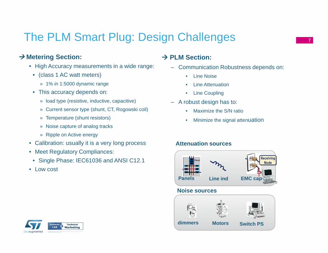
���� Metering Section:• High Accuracy measurements in a wide range:
• (class 1 AC watt meters)
» 1% in 1:5000 dynamic range
• This accuracy depends on:
» load type (resistive, inductive, capacitive)
» Current sensor type (shunt, CT, Rogowski coil)
» Temperature (shunt resistors)
» Noise capture of analog tracks
» Ripple on Active energy
• Calibration: usually it is a very long process
• Meet Regulatory Compliances:
• Single Phase: IEC61036 and ANSI C12.1
• Low cost
The PLM Smart Plug: Design Challenges
���� PLM Section:– Communication Robustness depends on:
• Line Noise
• Line Attenuation
• Line Coupling
– A robust design has to:
• Maximize the S/N ratio
• Minimize the signal attenuation
dimmers Motors
Noise sources
Switch PS
Panels
Attenuation sources
Line ind EMC cap
7

The PLM Smart Plug demo board: overview
Key Features:
• Energy consumption and electrical parameters monitoring
• Relay modes for On/Off features
• STPM01/10 energy meter IC
• Network/Standalone operative mode
Connectivity: Power Line Modem – ST7540 BFSK 4.8Kbs
Typical Applications:
Smart Grid
Home/building automation systems
Intelligent Wall Plug to monitor/manage remotely en ergy consumption by Power Line Modem
STEVAL-IHP002V2
STM32F103CBT6 32-bit MCU ARM Cortex-M3
STPM01 Energy meter
ST7540 B-FSK PLM
ALTAIR05T-800 AC/DC switching regulator
LD1117ADT33TR 3.3V linear regulator
5.6cm
8.7cm
8
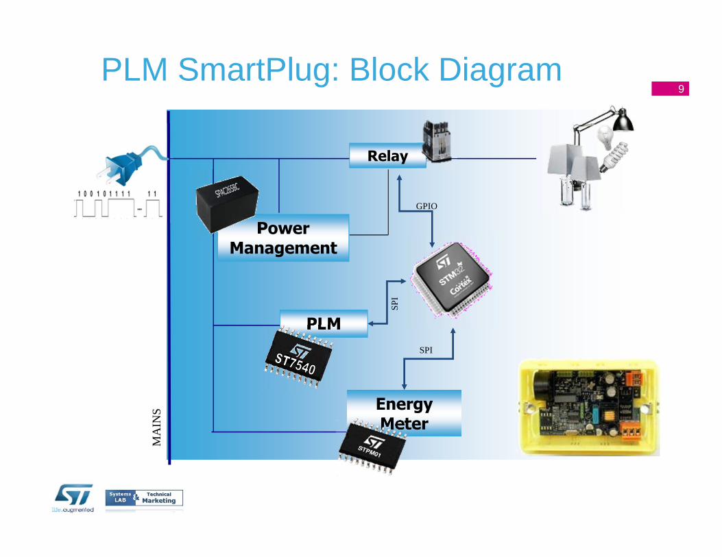
PLM SmartPlug: Block Diagram
MA
INS Energy
Meter
SPI
PLM
Power Management
Relay
GPIO
SPI
9
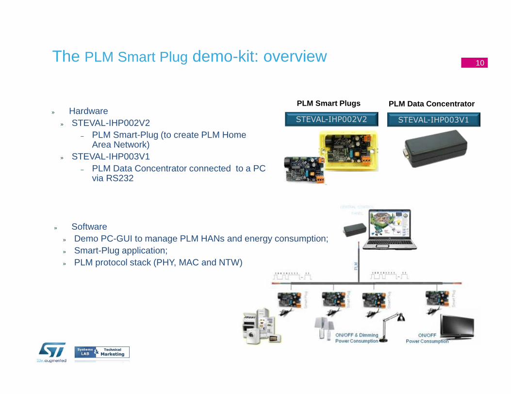
The PLM Smart Plug demo-kit: overview
PLM Smart Plugs PLM Data Concentrator
STEVAL-IHP002V2 STEVAL-IHP003V1» Hardware
» STEVAL-IHP002V2 – PLM Smart-Plug (to create PLM Home
Area Network)» STEVAL-IHP003V1
– PLM Data Concentrator connected to a PC via RS232
» Software» Demo PC-GUI to manage PLM HANs and energy consumption;» Smart-Plug application;» PLM protocol stack (PHY, MAC and NTW)
10
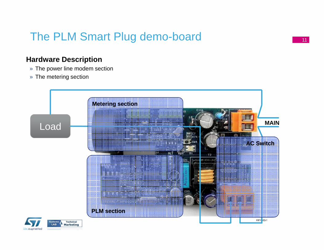
11The PLM Smart Plug demo-board
Hardware Description» The power line modem section» The metering section
Load MAIN
PLM sectionPLM section
Metering sectionMetering section
AC SwitchAC Switch
11
12
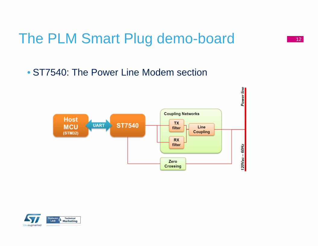
• ST7540: The Power Line Modem section
The PLM Smart Plug demo-board 12
13
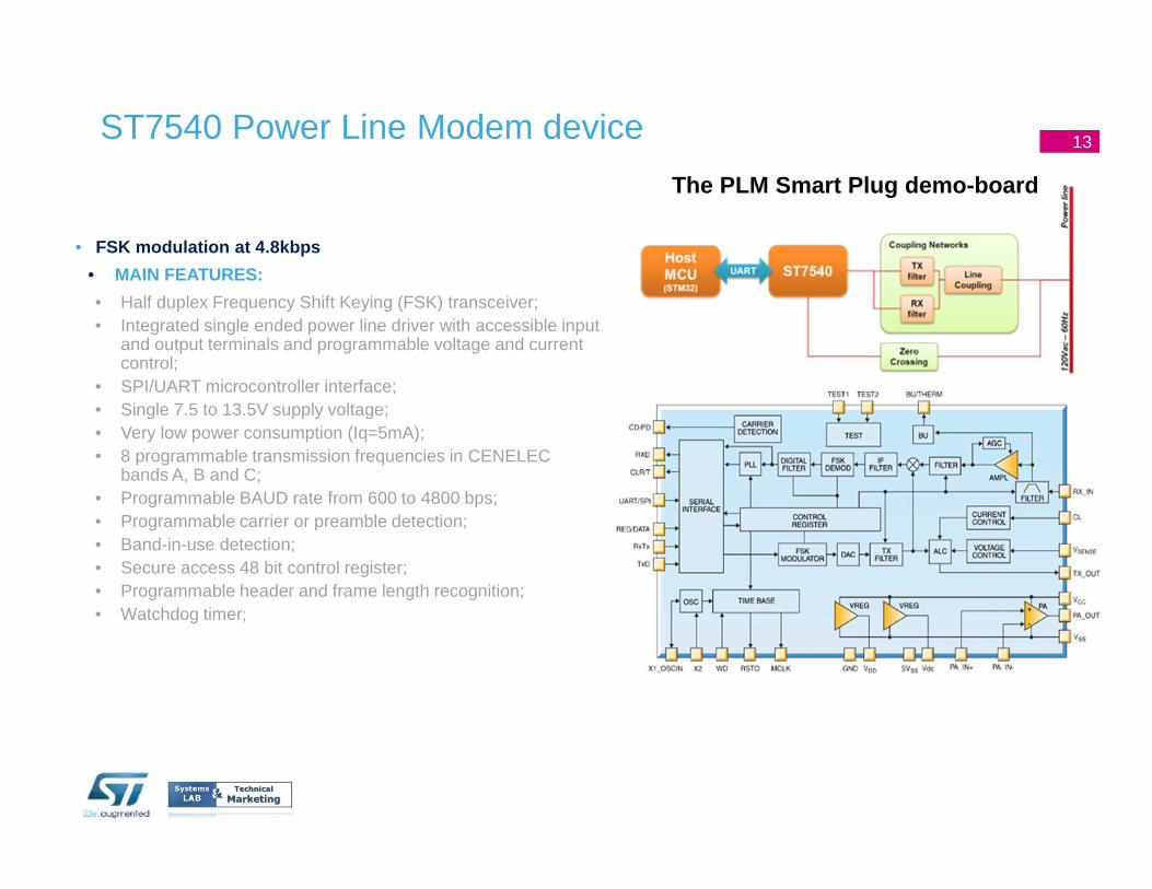
• FSK modulation at 4.8kbps
• MAIN FEATURES:
• Half duplex Frequency Shift Keying (FSK) transceiver; • Integrated single ended power line driver with accessible input
and output terminals and programmable voltage and current control;
• SPI/UART microcontroller interface; • Single 7.5 to 13.5V supply voltage; • Very low power consumption (Iq=5mA); • 8 programmable transmission frequencies in CENELEC
bands A, B and C; • Programmable BAUD rate from 600 to 4800 bps; • Programmable carrier or preamble detection; • Band-in-use detection; • Secure access 48 bit control register; • Programmable header and frame length recognition; • Watchdog timer;
ST7540 Power Line Modem device
The PLM Smart Plug demo-board
13
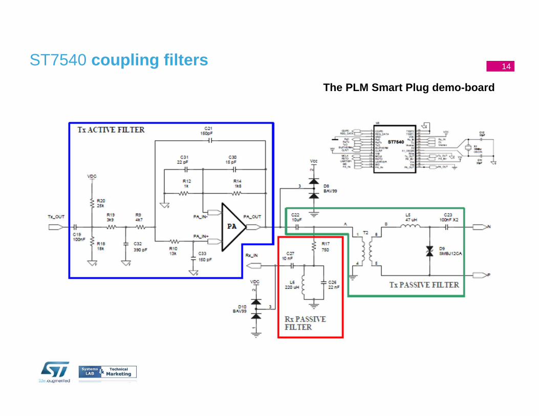
14ST7540 coupling filters
The PLM Smart Plug demo-board
14
15
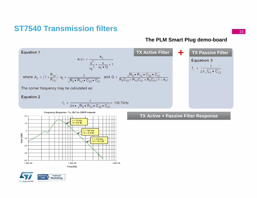
The PLM Smart Plug demo-board
TX Active Filter TX Passive Filter
TX Active + Passive Filter Response
+
ST7540 Transmission filters 15
16
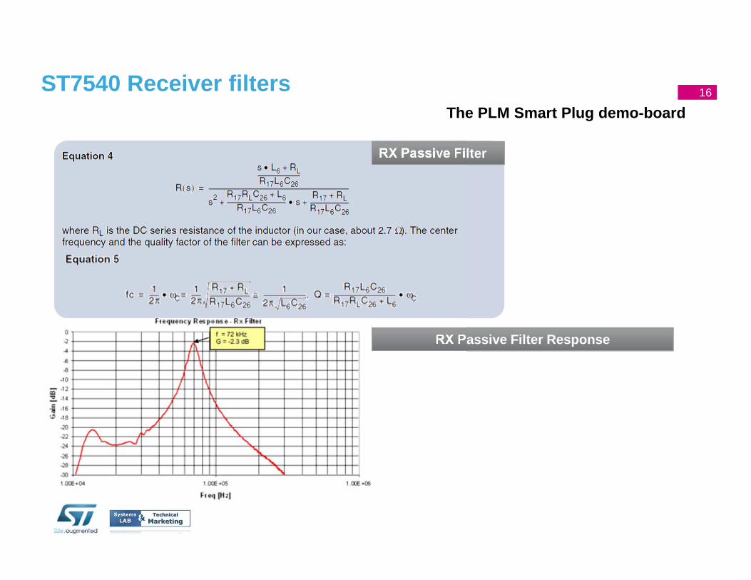
The PLM Smart Plug demo-board
RX Passive Filter
RX Passive Filter Response
ST7540 Receiver filters 16
17
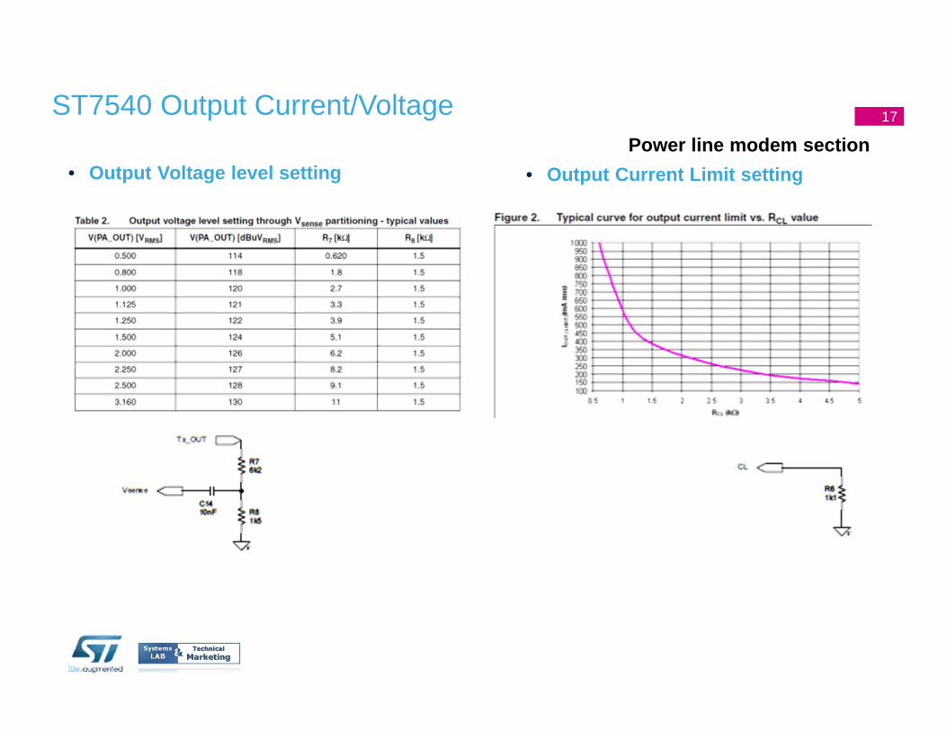
• Output Voltage level settingPower line modem section
• Output Current Limit setting
ST7540 Output Current/Voltage 17
18
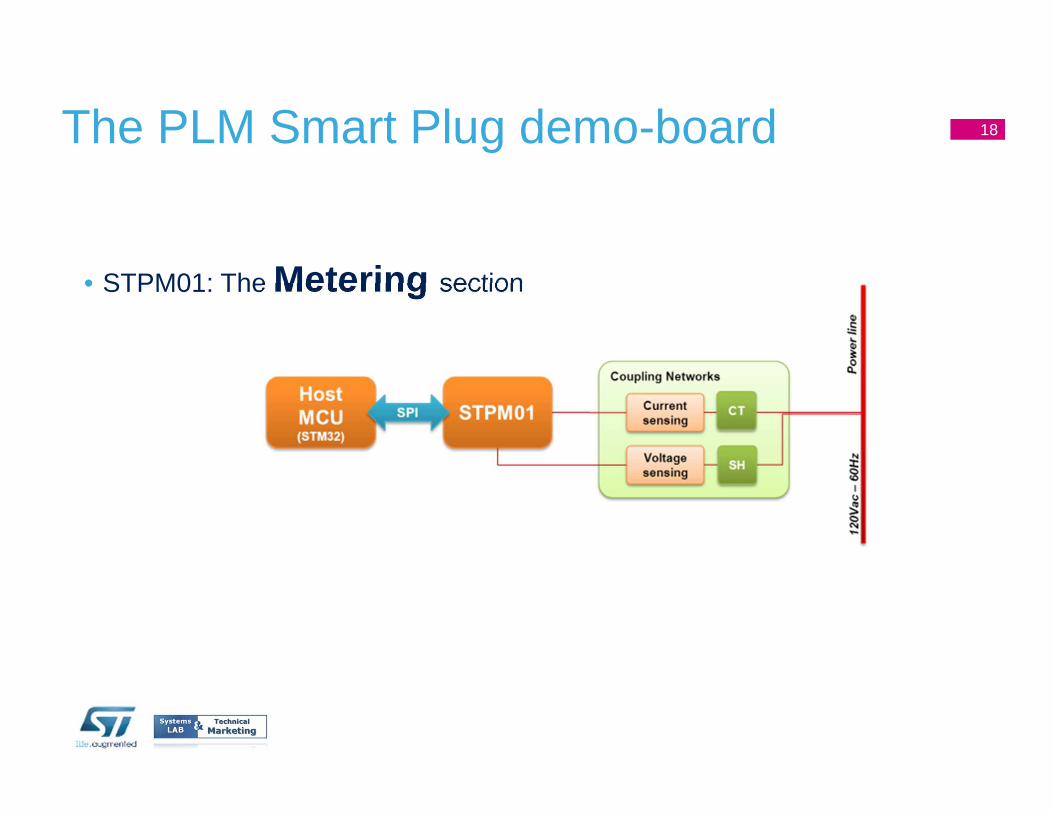
• STPM01: The Metering section
The PLM Smart Plug demo-board 18
19
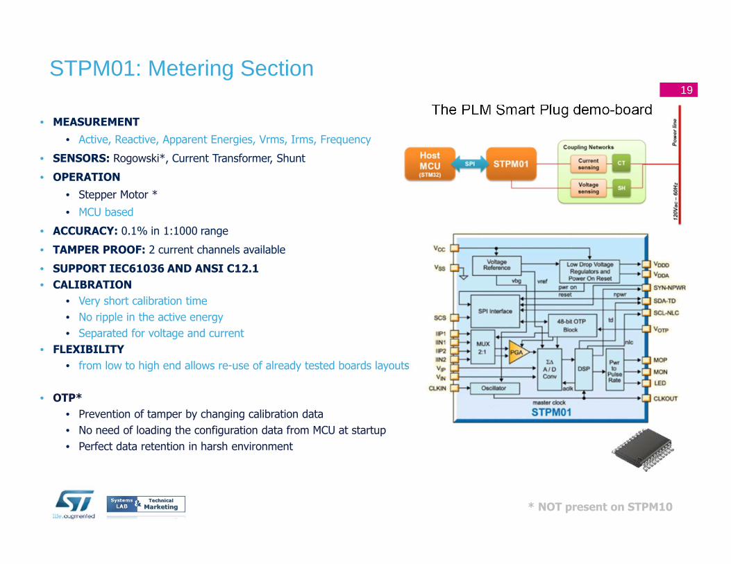
• MEASUREMENT
• Active, Reactive, Apparent Energies, Vrms, Irms, Frequency
• SENSORS: Rogowski*, Current Transformer, Shunt
• OPERATION
• Stepper Motor *
• MCU based
• ACCURACY: 0.1% in 1:1000 range
• TAMPER PROOF: 2 current channels available
• SUPPORT IEC61036 AND ANSI C12.1
• CALIBRATION
• Very short calibration time
• No ripple in the active energy
• Separated for voltage and current
• FLEXIBILITY
• from low to high end allows re-use of already tested boards layouts
• OTP*
• Prevention of tamper by changing calibration data
• No need of loading the configuration data from MCU at startup
• Perfect data retention in harsh environment
The PLM Smart Plug demo-board
STPM01: Metering Section19
* NOT present on STPM10
20
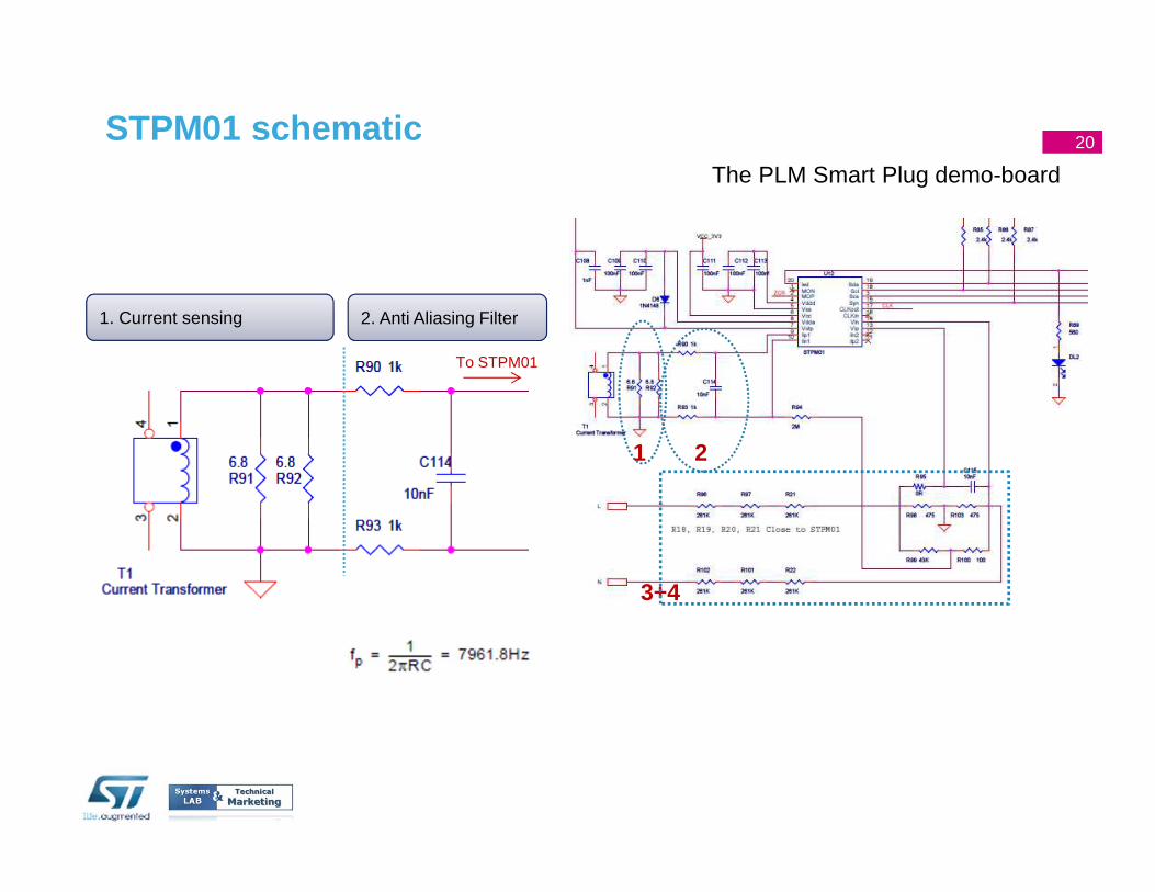
The PLM Smart Plug demo-board
1. Current sensing 2. Anti Aliasing Filter
1 2
3+4
STPM01 schematic
To STPM01
20
21
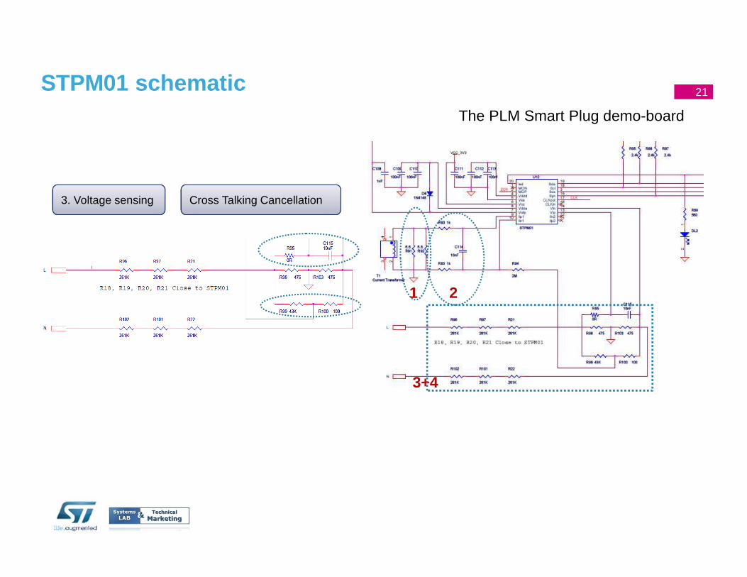
The PLM Smart Plug demo-board
3. Voltage sensing Cross Talking Cancellation
STPM01 schematic
1 2
3+4
21
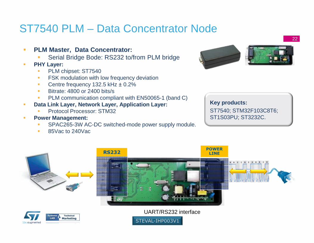
� PLM Master, Data Concentrator:� Serial Bridge Bode: RS232 to/from PLM bridge
� PHY Layer:� PLM chipset: ST7540� FSK modulation with low frequency deviation� Centre frequency 132.5 kHz ± 0.2%� Bitrate: 4800 or 2400 bits/s� PLM communication compliant with EN50065-1 (band C)
� Data Link Layer, Network Layer, Application Layer:� Protocol Processor: STM32
� Power Management:� SPAC265-3W AC-DC switched-mode power supply module.� 85Vac to 240Vac
ST7540 PLM – Data Concentrator Node
UART/RS232 interface
STEVAL-IHP003V1
Key products:ST7540; STM32F103C8T6; ST1S03PU; ST3232C.
RS232POWER
LINE
22
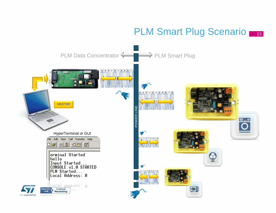
PLM Smart Plug Scenario
MASTER
PO
WE
R L
INE
HyperTerminal or GUI
PLM Data Concentrator PLM Smart Plug
23
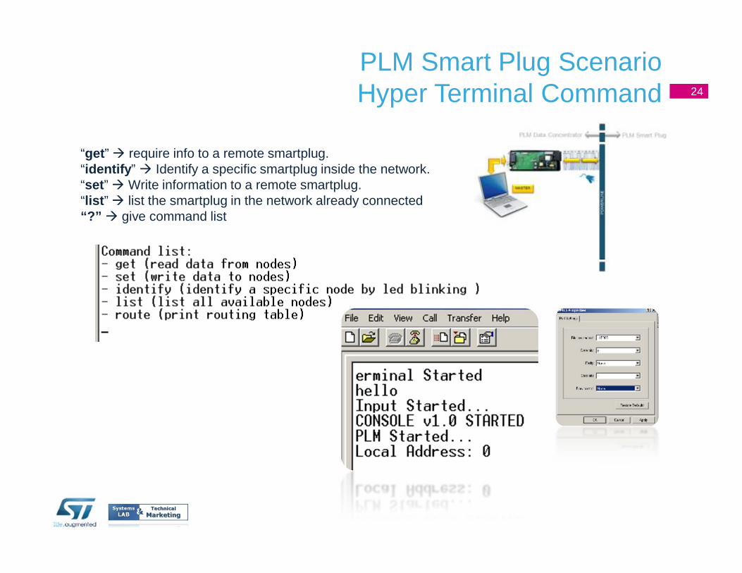
“get ” � require info to a remote smartplug.“identify ” � Identify a specific smartplug inside the network.“set ” � Write information to a remote smartplug. “list ” � list the smartplug in the network already connected“?” � give command list
PLM Smart Plug ScenarioHyper Terminal Command 24

PLM SmartPlug: Firmware Overview
25
PLM SmartPlug: Communication Protocol Overview
OverviewPower Line Modem Communication compliant to EN50065-1 (band C)FSK, FEC correctionData frame with max length of 100 bytes, CRC16, fixed ACK frameNetwork and Transport layers customized for the specific application.
General Specifaction� Static Network plus repeater� Node address set by serial communication� Node repeater function set by serial communication� MAC function with FEC
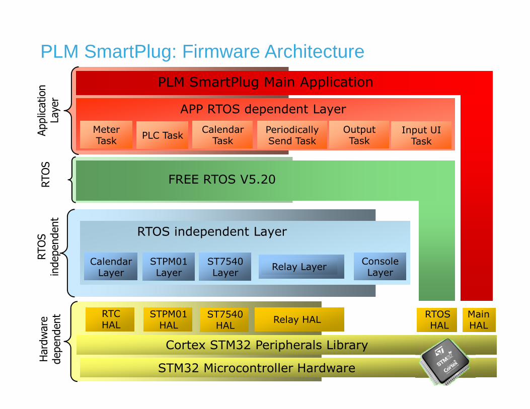
PLM SmartPlug: Firmware Architecture
STM32 Microcontroller Hardware
Cortex STM32 Peripherals Library
Hardware
dependent
RTOS
independent
FREE RTOS V5.20
PLM SmartPlug Main Application
Application
Layer
APP RTOS dependent Layer
STPM01 HAL
RTOSHAL
MainHAL
RTOS independent Layer
Meter TaskMeter Task
PLC TaskPLC TaskOutput TaskOutput Task
Periodically Send TaskPeriodically Send Task
CalendarTask
CalendarTask
RTOS
CalendarLayer
CalendarLayer
STPM01 LayerSTPM01 Layer
ST7540 LayerST7540 Layer
RTCHAL
ST7540 HAL
Relay LayerRelay Layer
Relay HAL
Input UI Task
Input UI Task
Console LayerConsole Layer
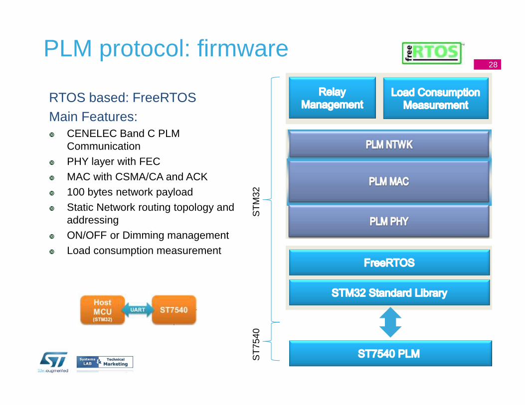
PLM protocol: firmware
RTOS based: FreeRTOSMain Features:� CENELEC Band C PLM
Communication� PHY layer with FEC� MAC with CSMA/CA and ACK� 100 bytes network payload� Static Network routing topology and
addressing� ON/OFF or Dimming management� Load consumption measurement
ST
M32
ST
7540
28
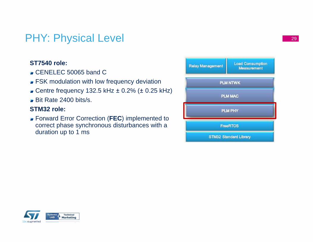
PHY: Physical Level
ST7540 role:CENELEC 50065 band C
FSK modulation with low frequency deviationCentre frequency 132.5 kHz ± 0.2% (± 0.25 kHz)
Bit Rate 2400 bits/s.
STM32 role:Forward Error Correction (FEC) implemented to correct phase synchronous disturbances with a duration up to 1 ms
29
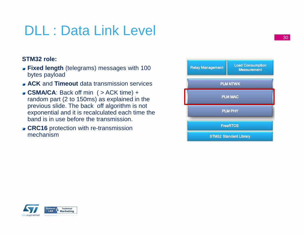
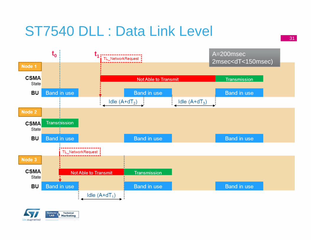
DLL : Data Link Level
STM32 role:Fixed length (telegrams) messages with 100 bytes payload
ACK and Timeout data transmission services
CSMA/CA : Back off min ( > ACK time) + random part (2 to 150ms) as explained in the previous slide. The back off algorithm is not exponential and it is recalculated each time the band is in use before the transmission.
CRC16 protection with re-transmission mechanism
30
31
t0 A=200msec2msec<dT<150msec)
t1
ST7540 DLL : Data Link Level31
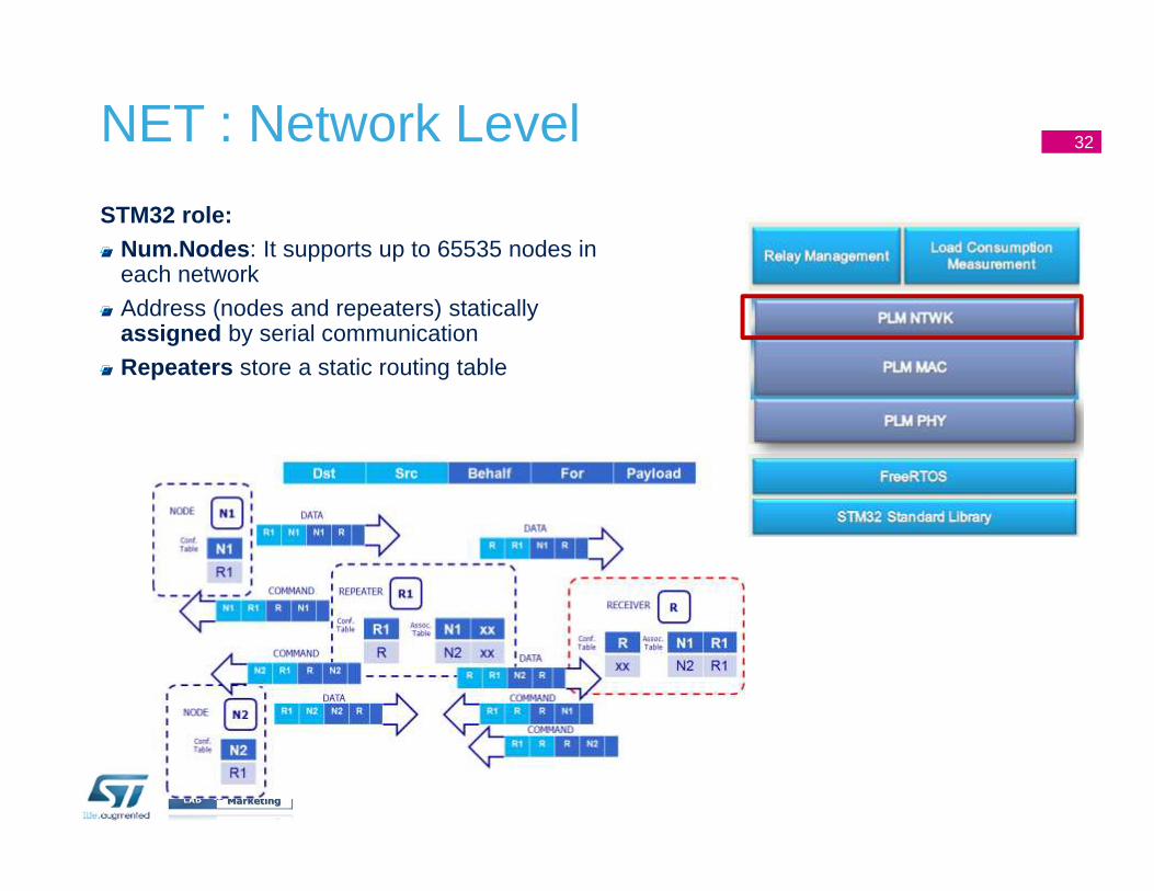
NET : Network Level
STM32 role:Num.Nodes : It supports up to 65535 nodes in each network
Address (nodes and repeaters) statically assigned by serial communication
Repeaters store a static routing table
32
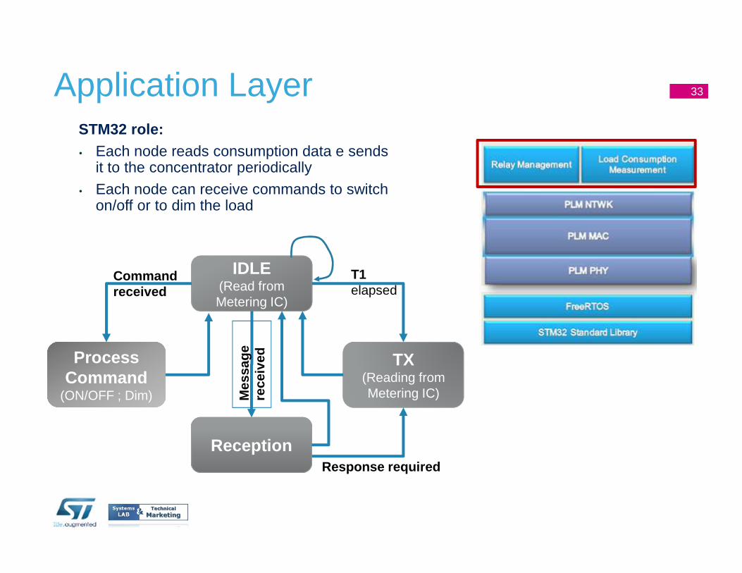
Application LayerSTM32 role:• Each node reads consumption data e sends
it to the concentrator periodically
• Each node can receive commands to switch on/off or to dim the load
IDLE(Read from Metering IC)
Process Command
(ON/OFF ; Dim)
Process Command
(ON/OFF ; Dim)
TX(Reading from Metering IC)
Reception
T1elapsed
Command received
Mes
sage
rece
ived
Response required
33
16/10/2012Presentation Title
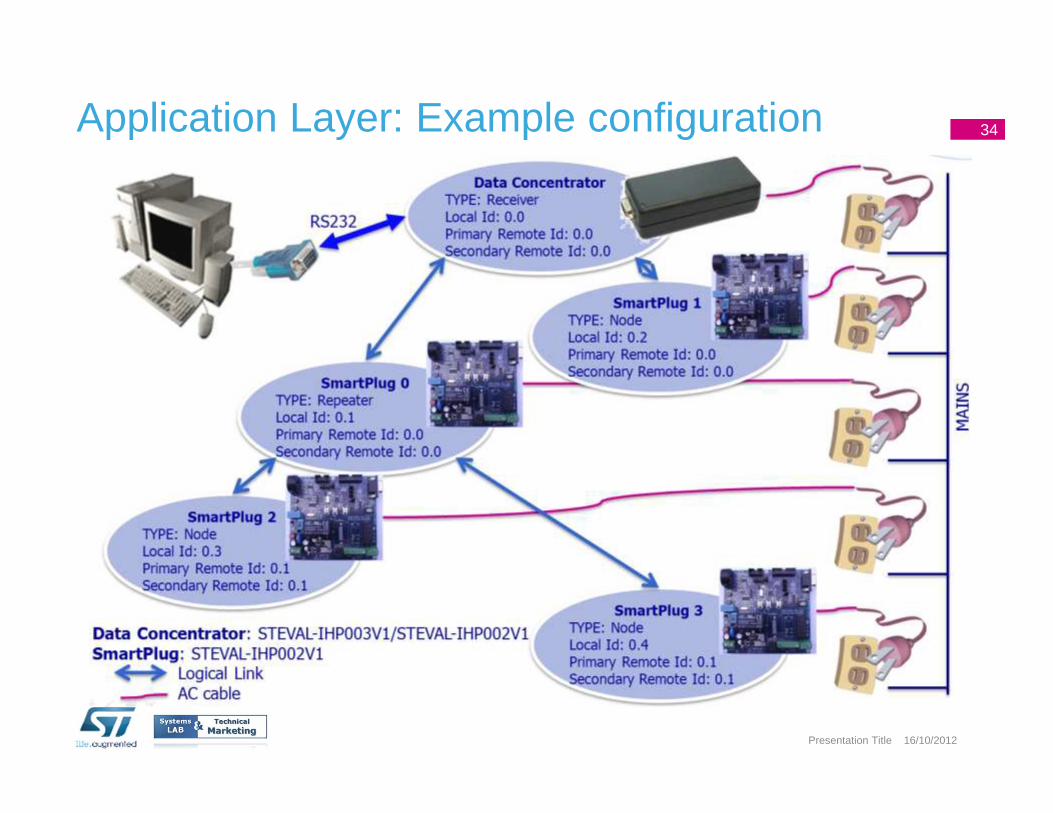
Application Layer: Example configuration 34
PLM SmartPlug: ST products Overview
35
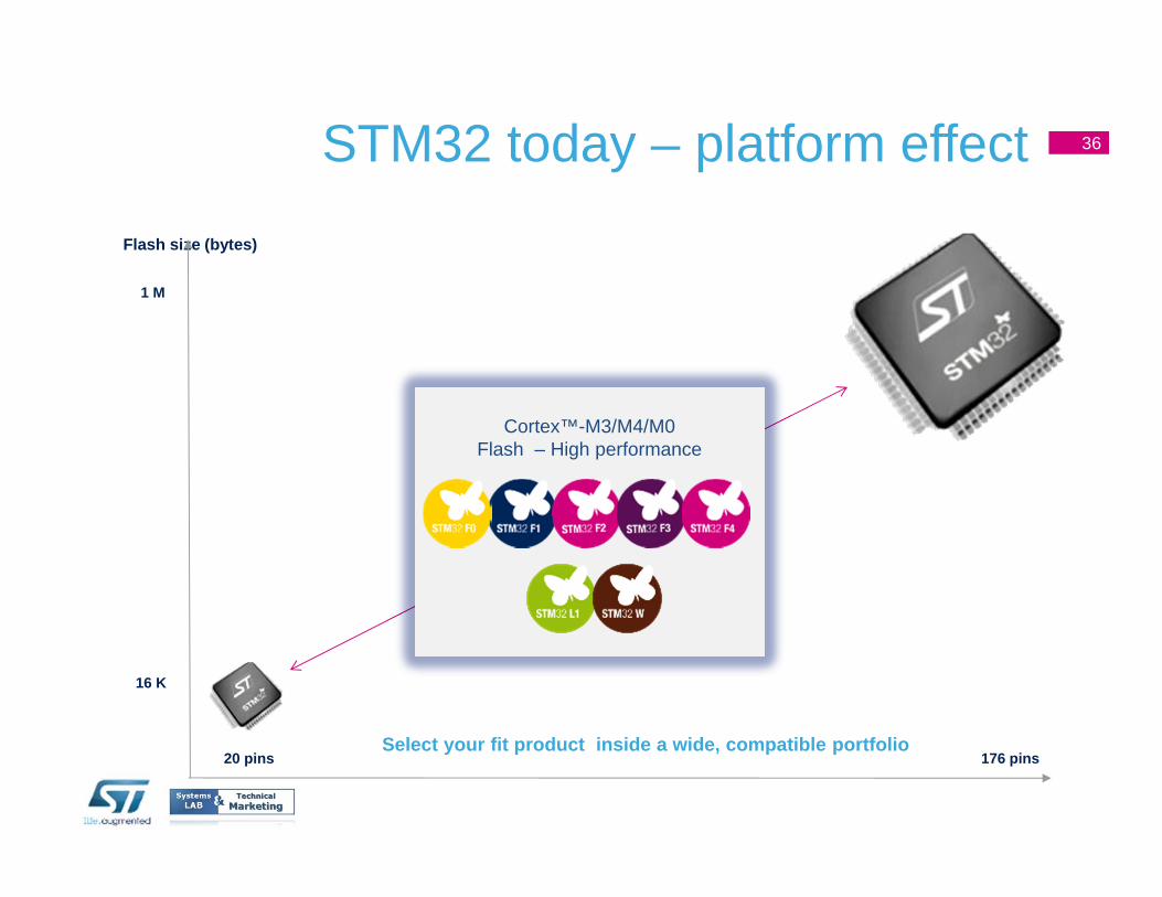
STM32 today – platform effect 36
Flash size (bytes)
Select your fit product inside a wide, compatible port folio
1 M
16 K
20 pins
Cortex™-M3/M4/M0Flash – High performance
176 pins
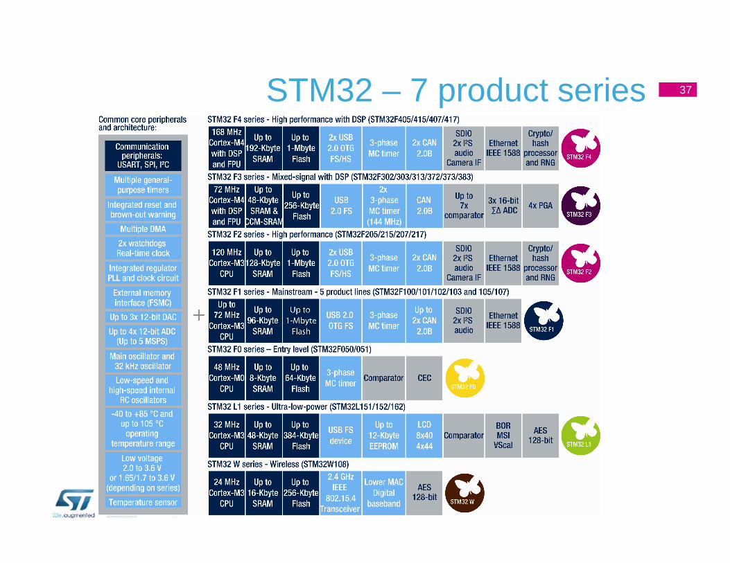
STM32 – 7 product series 37
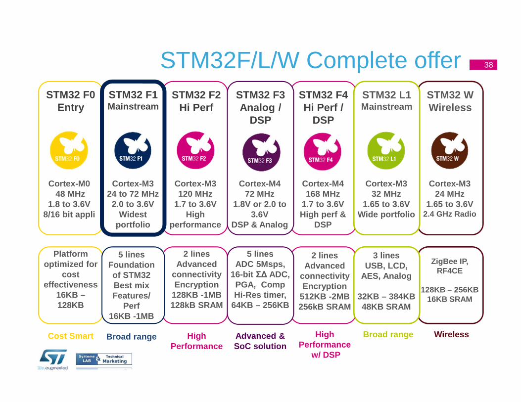
STM32F/L/W Complete offer 38
Platform optimized for
cost effectiveness
16KB –128KB
Cost Smart
STM32 F0Entry
Cortex-M0 48 MHz
1.8 to 3.6V8/16 bit appli
STM32 F2Hi Perf
Cortex-M3 120 MHz
1.7 to 3.6VHigh
performance
2 linesAdvanced
connectivityEncryption
128KB -1MB128kB SRAM
High Performance
2 linesAdvanced
connectivityEncryption
512KB -2MB256kB SRAM
High Performance
w/ DSP
STM32 F4Hi Perf /
DSP
Cortex-M4168 MHz
1.7 to 3.6VHigh perf &
DSP
2 linesAdvanced
connectivityEncryption
512KB -2MB256kB SRAM
Wireless
STM32 WWireless
Cortex-M3 24 MHz
1.65 to 3.6V2.4 GHz Radio
ZigBee IP, RF4CE
128KB – 256KB16KB SRAM
STM32 F3Analog /
DSP
Cortex-M4 72 MHz
1.8V or 2.0 to 3.6V
DSP & Analog
5 linesADC 5Msps,
16-bit Σ∆ ADC, PGA, CompHi-Res timer,
64KB – 256KB
Advanced & SoC solution
2 linesAdvanced
connectivityEncryption
512KB -2MB256kB SRAM
Broad range
STM32 L1Mainstream
Cortex-M3 32 MHz
1.65 to 3.6VWide portfolio
3 linesUSB, LCD,
AES, Analog
32KB – 384KB48KB SRAM
STM32 F1Mainstream
Cortex-M3 24 to 72 MHz2.0 to 3.6V
Widest portfolio
5 linesFoundation of STM32Best mix Features/
Perf16KB -1MB
Broad range
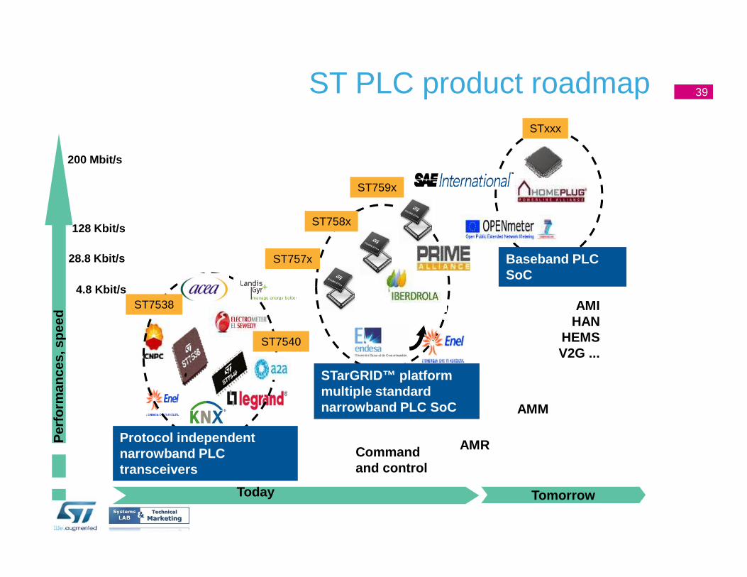
ST PLC product roadmap
Tomorrow
Per
form
ance
s, s
peed
Today
Protocol independentnarrowband PLC transceivers
Command and control
AMR
AMM
AMIHAN
HEMSV2G ...
Baseband PLC SoC
STarGRID™ platformmultiple standard narrowband PLC SoC
ST757x
ST758x
ST7538
ST7540
STxxx
ST759x
4.8 Kbit/s
128 Kbit/s
28.8 Kbit/s
200 Mbit/s
39
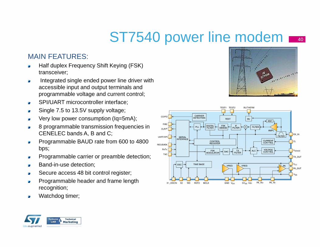
ST7540 power line modemMAIN FEATURES:
Half duplex Frequency Shift Keying (FSK) transceiver; Integrated single ended power line driver with accessible input and output terminals and programmable voltage and current control; SPI/UART microcontroller interface; Single 7.5 to 13.5V supply voltage; Very low power consumption (Iq=5mA); 8 programmable transmission frequencies in CENELEC bands A, B and C; Programmable BAUD rate from 600 to 4800 bps; Programmable carrier or preamble detection; Band-in-use detection; Secure access 48 bit control register; Programmable header and frame length recognition; Watchdog timer;
40
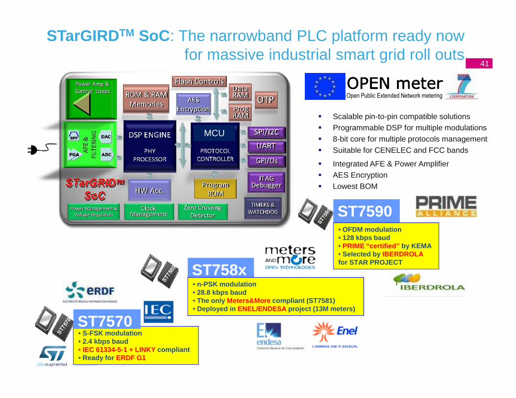
• S-FSK modulation• 2.4 kbps baud• IEC 61334-5-1 + LINKY compliant• Ready for ERDF G1
� Integrated AFE & Power Amplifier� AES Encryption� Lowest BOM
� Scalable pin-to-pin compatible solutions� Programmable DSP for multiple modulations� 8-bit core for multiple protocols management� Suitable for CENELEC and FCC bands
OPEN meterOPEN meterOPEN meterOPEN meterOpen Public Extended Network metering
MCU
STarGIRDTM SoC: The narrowband PLC platform ready now for massive industrial smart grid roll outs
ST7570
ST758x• n-PSK modulation• 28.8 kbps baud• The only Meters&More compliant (ST7581)• Deployed in ENEL/ENDESA project (13M meters)
ST7590• OFDM modulation• 128 kbps baud• PRIME “certified” by KEMA• Selected by IBERDROLAfor STAR PROJECT
41
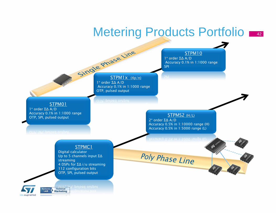
STPM011° order Σ∆ A/DAccuracy 0.1% in 1:1000 rangeOTP, SPI, pulsed output
STPM1x (4p/n)
1° order Σ∆ A/DAccuracy 0.1% in 1:1000 rangeOTP, pulsed output
Metering Products Portfolio
STPMC1Digital calculatorUp to 5 channels input Σ∆ streaming4 DSPs for Σ∆ i/u streaming112 configuration bitsOTP, SPI, pulsed output
STPMS2 (H/L)
2° order Σ∆ A/DAccuracy 0.5% in 1:10000 range (H)Accuracy 0.5% in 1:5000 range (L)
STPM101° order Σ∆ A/DAccuracy 0.1% in 1:1000 rangeSPI
42
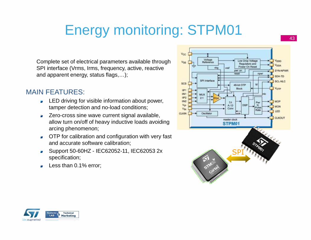
Energy monitoring: STPM01
Complete set of electrical parameters available through SPI interface (Vrms, Irms, frequency, active, reactive and apparent energy, status flags,…);
MAIN FEATURES:LED driving for visible information about power, tamper detection and no-load conditions;Zero-cross sine wave current signal available, allow turn on/off of heavy inductive loads avoiding arcing phenomenon;OTP for calibration and configuration with very fast and accurate software calibration;Support 50-60HZ - IEC62052-11, IEC62053 2x specification;Less than 0.1% error;
SPI
43
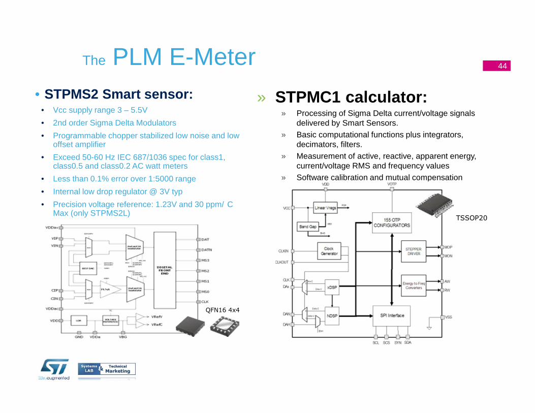
• STPMS2 Smart sensor:• Vcc supply range 3 – 5.5V
• 2nd order Sigma Delta Modulators
• Programmable chopper stabilized low noise and low offset amplifier
• Exceed 50-60 Hz IEC 687/1036 spec for class1, class0.5 and class0.2 AC watt meters
• Less than 0.1% error over 1:5000 range
• Internal low drop regulator @ 3V typ
• Precision voltage reference: 1.23V and 30 ppm/ C Max (only STPMS2L)
The PLM E-Meter
» STPMC1 calculator:» Processing of Sigma Delta current/voltage signals
delivered by Smart Sensors.» Basic computational functions plus integrators,
decimators, filters.» Measurement of active, reactive, apparent energy,
current/voltage RMS and frequency values» Software calibration and mutual compensation
TSSOP20
QFN16 4x4
44
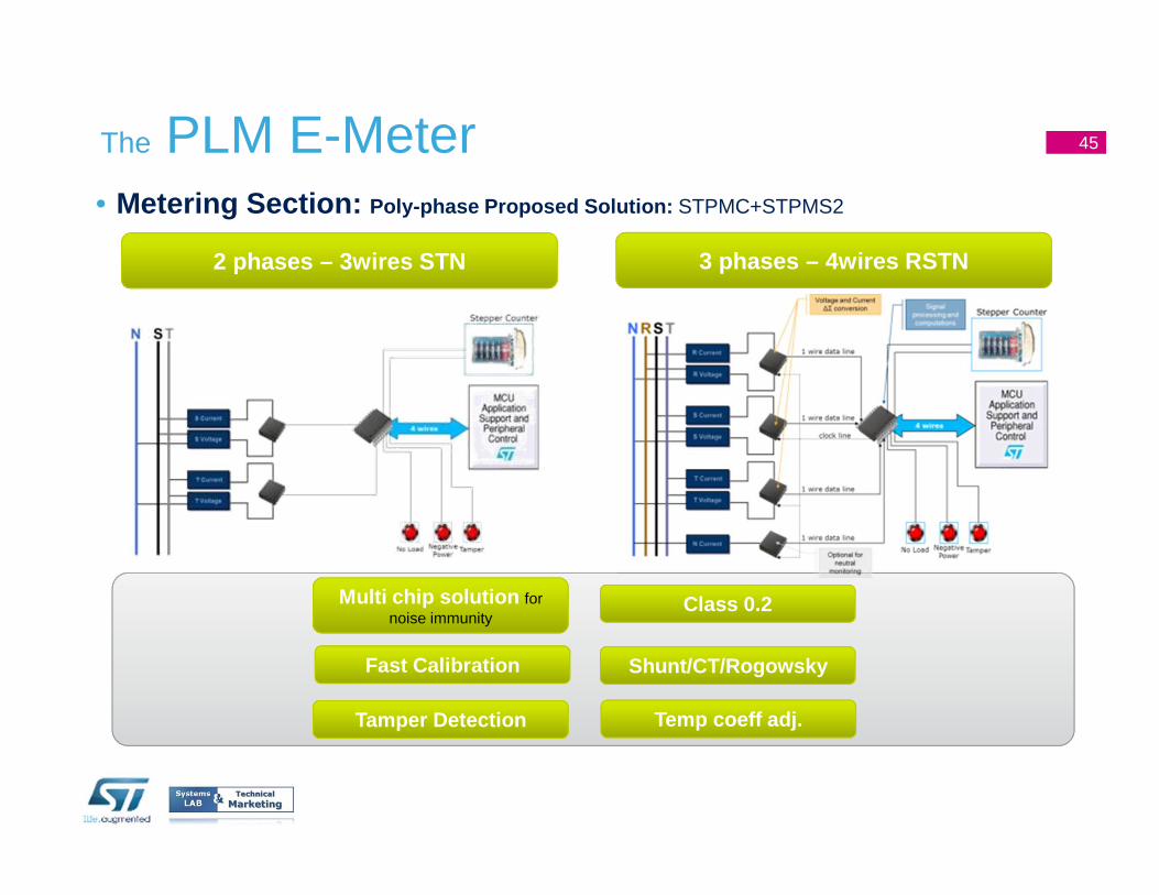
• Metering Section: Poly-phase Proposed Solution: STPMC+STPMS2
The PLM E-Meter
Class 0.2
Shunt/CT/Rogowsky
Temp coeff adj.
Multi chip solution for noise immunity
Fast Calibration
Tamper Detection
2 phases – 3wires STN 3 phases – 4wires RSTN
45

Thank You
46
16/10/2012Presentation Title